1. Introduction
The constantly increasing global population and the simultaneous growth in the proportion of urbanization has lead to increased demand for transportation systems in cities. Despite the obvious benefits of further expanding public transport, it is also important to improve the efficiency of passenger city cars. Indeed the increasing popularity of car-sharing services plays a crucial role in promoting the adoption of city cars, which are compact, fuel-efficient, and easy to maneuver, making them well suited for short trips within urban environments. In particular, authors in [
1] concluded that electric car-sharing fleets lead to a consistent reduction of CO
emissions. The study presented in [
2] highlights the challenges of electric vehicles related to long-distance transportation, implicitly pointing out the opportunity for hybrid vehicles to have an important role. Further, in [
3], a study conducted in several German cities revealed that the existence of a car-sharing system significantly reduces the necessity of owning a personal car, leading to significant implications for public transportation utilization as well.
All the cited studies emphasise the importance of increasing the efficiency of the a-segment cars, however, the exact approach to achieve this goal is not entirely clear. Electric cars face limitations such as reduced driving range, inadequate charging infrastructure, and cost/environmental concerns related to current battery technologies [
4]. On the other hand, hybrid electric vehicles have been shown to be a reliable compromise, particularly in urban environments, offering low emissions and fuel consumption. Hybrid electric city cars are expected to reach the highest share of the urban vehicle fleet in the future. Demand for hybrid electric cars is booming and an increase in new vehicle sales is predicted, but the transition towards full hybrid city cars is not trivial, due to both the high costs and the large inertia of the used vehicle market. Therefore, an intermediate step might be the retrofitting of existing vehicles [
5,
6], which is a path already taken by some car manufacturers who are moving in this direction [
7]. For this reason, our study investigates a mild-hybrid retrofit opportunity of an existing city car powertrain.
Among the various interventions that can be applied to existing vehicles to enhance performance and reduce emissions, exhaust gas heat recovery has emerged as a pivotal strategy, alongside powertrain electrification involving the integration of batteries and electric motors.
The inclusion of an energy storage device, such as a battery, encourages the utilization of systems that harness the thermal energy contained in exhaust gases to generate electricity. Many studies have explored the possibility of powering thermodynamic cycles using this heat source. Specifically, for heavy-duty applications, solutions employing organic Rankine cycles, with the incorporation of an exhaust gas-organic fluid heat exchanger to drive the turbine, are of particular interest [
8,
9]. These solutions enable some degree of energy recovery, although they are only economically viable for vehicles that combine high-rated-power engines and have minimal constraints in terms of weight and space to accommodate the waste heat recovery steam generator.
This topic has been already extensively investigated in the literature. In [
10] the authors focus on a turbo-compounding system that utilizes a 48 V electric motor to assist the turbocharger compressor, aiming at improving the overall efficiency and performance of the internal combustion gasoline engine, while recovering energy from a turbine driven by air heated by the exhaust gases. The results demonstrated that the proposed turbo-compounding system led to significant improvements in the energy efficiency of the gasoline engine, however the study uses a large 2 L four-cylinder engine and analyzes the performance of the system solely through steady-state simulations. Similarly, authors in [
11] studied the case of mechanical turbo-compounding for a heavy-duty diesel engine, showing important improvements in performance. Another study [
12] focuses on the modeling of a turbo-compound power unit for a series hybrid vehicle application using a supercapacitor. Through simulations and experimental data analysis, the researchers validate the model and assess the performance of the turbo-compound power unit in terms of fuel efficiency and power delivery. The results demonstrate the effectiveness of the model in accurately predicting the behavior of the power unit and its impact on the overall performance of the series hybrid vehicle powered by a 2 L turbocharged diesel engine. Eggimann et al. [
13] made only a numerical analysis on the benefits of the electrically assisted turbocharger in a hybrid electric vehicle powered by a 1.3 L gasoline engine. A recent work by Pipitone et al. [
14] evaluates with a theoretical approach the efficiency improvements obtainable by the separated compound electric engine in comparison with a traditional turbocharged engine for hybrid vehicle applications. The study [
15] is centered on assessing the advantages arising from the implementation of an Electric Turbo-Compound (ETC) system on a small twin-cylinder SI engine (900 cm
). Utilizing the experimental maps of two turbines and one compressor and the information collectible from a pre-existing experimental database, a comprehensive model of the turbocharged engine was developed using the AVL BOOST one-dimensional code.
The aforementioned studies collectively show the promising potential of turbo- compounding in hybrid applications. In line with this trajectory, the authors of the present research have identified substantial opportunities for innovation and scientific impact in applying and evaluating the performance of a turbo-compound system on a spark-ignition (SI) three-cylinder, 1 L supercharged engine within an electrified city car, employing a 48 V system. This study distinguishes itself from previous works through its unique combination of an experimental numerical approach and its specific focus on a small city car engine, which holds significant potential for shaping the future automotive market.
With the aid of a 48 V battery pack, which is the widely adopted solution for mild-hybrid applications, it becomes feasible to operate the compressor using a 48 V electric motor and link the turbine to a generator that replenishes the battery. The mechanical decoupling of the compressor/turbine group allows both machines to be designed so that they operate at different speeds and close to the maximum efficiency point for most of the expected real operating time.
The first part of the work is dedicated to the experimental evaluation of the performance of the turbocharged engine, after which numerical simulations have been carried out in GT-Suite [
16] in order to build up a model with the pursuit of evaluating the benefits of turbo compounding. The model was calibrated by means of stationary experimental data and further validated through data derived from dynamic tests.
Finally the performance of the turbo-compound system is assessed, quantifying the amount of energy which can be recovered by the turbine from the exhaust gases.
4. Model Description
This study involves the development of a GT-SUITE engine model [
16]. A one-dimensional approach is utilized to model the entire gas flow system, with the pipes divided into coarse control volumes that maintain uniform pressure, temperature, and density. The momentum equation, as well as the energy and mass conservation equations, are simultaneously solved within each control volume. The model takes into account the precise gas path geometry by incorporating multiple elements to accurately represent the complex shape of the intake and exhaust collectors. Additionally, the air-box, inter-cooler, and catalytic converter are modeled as lumped flow volume elements.
The three cylinders are modeled through a 0D non predictive approach in crank-angle resolution, so as to simply implement the essential features of the combustion process and heat transfer. More specifically, the in-cylinder heat transfer will be solved via the classical Woschni correlation without swirl [
18], while a Wiebe function imposes the combustion burn rate for the spark-ignition engine [
19].
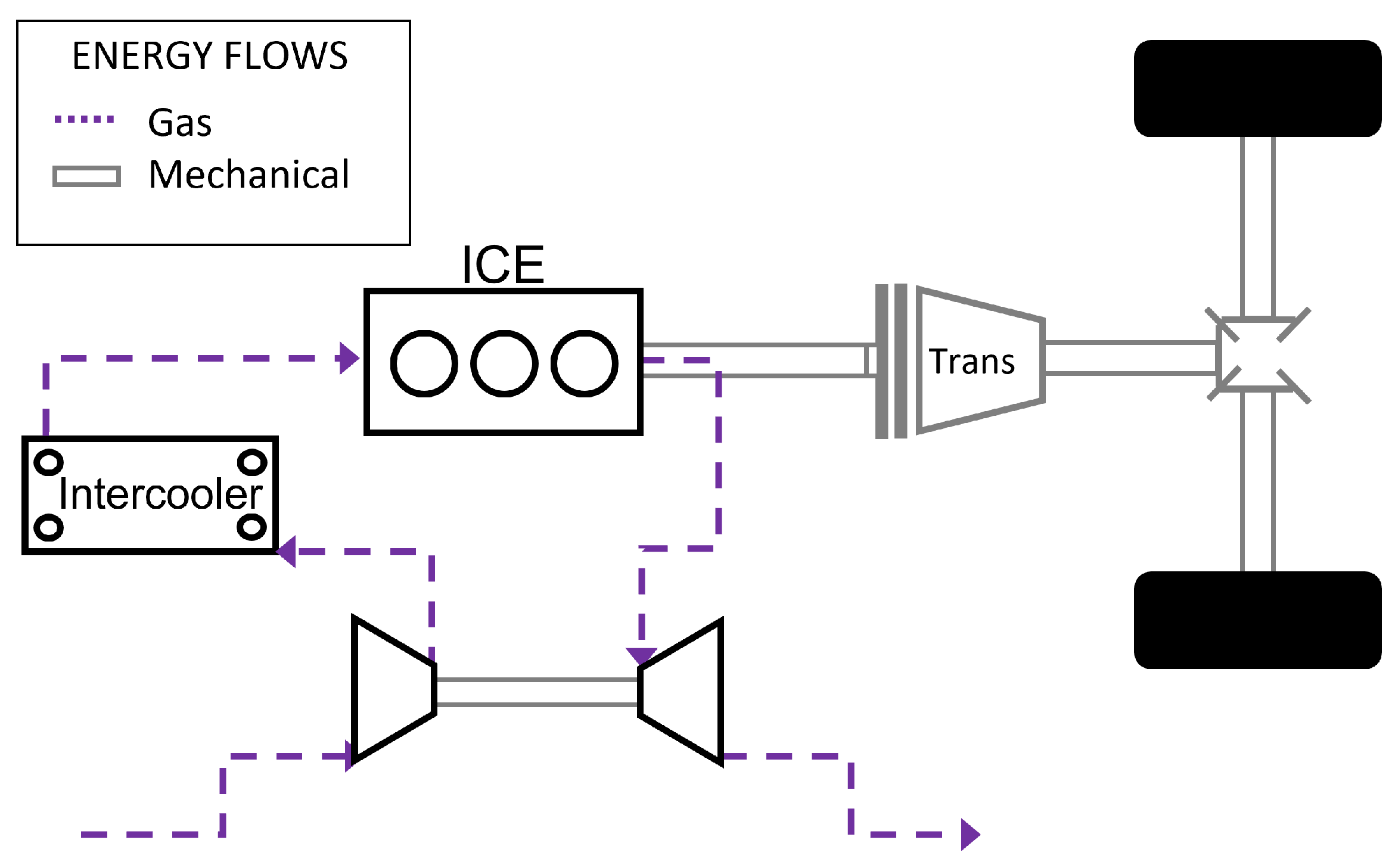
The turbocharging system is modeled by a mechanical connection of turbine and compressor through a shaft element. For turbine and compressor a 0D model is implemented, considering geometry and operating maps provided by the redesign of the original Mitsubishi turbocharger performed in [
20,
21]. It is important to note that the waste-gate valve, integrated into the turbine template, is controlled by a waste-gate controller to maintain a predefined intake pressure, see
Figure 4. The decision to use intake pressure as the target for the wastegate controller is based on the utilization of the faster and more accurate Kistler Kibox sensor, which provides pressure values that are more reliable than those obtained at the compressor outlet. In the final section of this paper, results for the turbo-compound model are presented, where the turbine and compressor are decoupled by removing the shaft and waste-gate elements, allowing both machines to freely rotate at different speeds
Figure 5. Since the purpose of this study is to assess the potential of the turbo-compound solution compared to the turbocharged solution, additional integrator blocks have been incorporated to calculate the integral of the instantaneous power of the turbine and compressor. This allows for the evaluation of the energy absorbed or generated by these components over the duration of the simulation.
5. Experimental Campaign
Preliminary experimental activities were carried out at different speeds, from 1500 rpm to 5000 rpm, at
0.9. The spark ignition timing (IT) of each operating point was set to achieve the maximum brake torque (MBT) which can be detected by positioning the in-cylinder peak pressure (APmax) in a range of 10–20 CAD aTDC, according to the specific case [
22]. First, spark IT was tuned with the engine operating at full throttle mode (i.e., hereafter referred to as High Load HL) to achieve the MBT condition. Five-hundred consecutive cycles were performed at each operating point. Following that, after determining the MBT at HL, the throttle position was varied to reach the operating condition featured with the 70% and 35% (i.e., hereafter referred to as Medium Load, ML and Low Load, LL) of the maximum Indicated Mean Effective Pressure IMEPn of the previous case (i.e., HL). Even in these scenarios, IT was optimized as much as possible to meet MBT requirements.
Figure 6 and
Figure 7 illustrate the outcomes of this optimization procedure, displaying the power and torque characteristics that represent the engine performance at the three analyzed load conditions.
Specifically, operating points above 3250 rpm have been tested without a specific control on the wastegate valve, resulting in the valve being mostly wide open during these operations. This led to engine performance similar to that of a naturally aspirated engine. These experiments were carried out mainly for the calibration of the ECU. For the operating points from 1500 rpm to 3250 rpm, the waste-gate is actuated so as to maximize the torque output, specifically the MBT, by optimizing the IT and preventing knocking occurrences. These experiments are representative of the real performance of the turbocharged engine and are used in the following section for the calibration of the GT-power model.
Table 2 reports some key engine operating parameters. For the sake of fluency, data are reported only for the high load conditions. A clear difference in the intake pressure can be observed between the points with forced induction and the points with the waste-gate fully open. This also results in a significant decrease, beyond 3250 rpm, in the maximum pressure reached in the cylinder.
6. Model Calibration
This section presents the calibration of the previously described GT-Power model, which has been carried out through the use of data available from the experimental campaign described in
Section 5 and performed on the original Smart 999-cc turbo engine under steady-state conditions. Nine operating points are specifically investigated through steady-state simulations and compared with the corresponding experimental results. These data points correspond to various combinations of engine speed (1500 rpm, 2500 rpm, and 3250 rpm) and throttle angles, representing maximum IMEP (Indicated Mean Effective Pressure), 70% IMEP, and 35% IMEP, respectively.
The set of parameters retrieved from the experiments are listed below:
Cylinders and intake and exhaust valve geometry and lift profile
Intake conditions (pressure and temperature in the intake collector)
Relative air–fuel ratio
, defined as per Equation (
1), where AFR is the air–fuel ratio and AFR
is the stoichiometric air–fuel ratio, and whose values are reported in
Table 3 for different loads
Friction losses
Angular parameters of combustion
Indicated pressure profile
Indicated and Brake Mean Effective Pressure (IMEP and BMEP)
It is worth emphasising that the values of
used, which are mostly far from the stoichiometric condition, represent a compromise between the desire to avoid knock events and the goal of maximizing engine performance as much as possible [
23].
The procedure followed to calibrate the GT-Power model and replicate the results of the experiments is as follows:
- 1.
Cylinders and intake and exhaust valves geometry and lift profile, relative air–fuel ratio, engine speed, combustion angle parameters and friction losses are imposed to the model;
- 2.
Intake pressure is set as the waste-gate controller target;
- 3.
The throttle valve angle is iteratively adjusted so as to obtain the intake pressure and temperature pair for each operating point, the air flow rate being a function of these parameters, which in turn depend on compressor efficiency, losses through the throttle valve and heat transfer through the intake collector;
- 4.
Once the correct flow rate is established in the engine, a calibration procedure on the combustion efficiency and Wiebe parameters is started in order to get a good agreement with indicated pressure profiles and IMEP/BMEP.
Equation (
2) defines the combustion efficiency. In that equation
and
are, respectively, the enthalpy of the reactant and the enthalpy of the product both evaluated at ambient temperature, while
is the fuel mass and
is the fuel lower heating value. The denominator represents the total energy supplied to the cylinder which can be released during the combustion process. The combustion efficiency is chosen as a calibration parameter since it accounts for the complex effects on the combustion process that cannot be captured by a simple Wiebe model.
Figure 8 shows the combustion efficiency for different engine speeds and throttle angles. As one may see, for the given relative air–fuel ratios, provided in
Table 3, the combustion efficiency results in their being proportional to the load (i.e., throttle valve angle) for speeds higher than 2500 rpm due to higher fluid velocity through the intake valves, which improves the turbulent air–gasoline mixing and, consequently, the combustion process. Instead, below 2500 rpm, the decrease of the combustion efficiency with the load is mostly explained through the lower values of the relative air–fuel ratio, which approximate the stoichiometric value when the load is low, and emulate a richer mixture when the throttle is fully open [
18].
In order to verify the effectiveness of the calibration process, the outputs of the model, namely BMEP and IMEP, are compared with the experimental data. IMEP is a good indicator of the engine performance and the comparison between experimental and simulated results is shown in both
Table 4 and
Figure 9.
Figure 10 also shows very good agreement with the indicated pressure profiles, proving that the engine behaviour is properly simulated in the model, while
Figure 11 depicts the net engine power at the nine calibration points, further demonstrating a strong correlation between the experimental data and the numerical ones, confirming that the experimentally derived friction curve accurately captures the mechanical losses of the real engine.
It is important to point out that the aim of these stationary simulations is not only to calibrate the model, but also to get the information necessary to control the engine in dynamic conditions. In fact, as a result of the stationary simulations, some control maps for both intake pressure and torque have been defined and are provided in
Figure 12a,b. These maps—given the power and speed requests—make it possible to control the throttle angle and the waste-gate diameter (i.e., intake pressure), in order to achieve the expected engine mass flow rate and brake torque. This is crucial to evaluate the performance of the original engine on a given driving profile and to evaluate the possible turbo-compounding benefits. In other words, these maps resume the functional relation between the inputs (speed and torque request) and the outputs of the powertrain controller for the dynamic simulations.
In
Figure 13, the agreement between the experimental and numerical compressor pressure ratios can be observed. Some discrepancies arise, most likely due to the discharge coefficient profile implemented in the throttle component, which lead to a slightly different pressure drop compared to the real throttle used in the experiments. To achieve a more precise calibration, additional data on the throttle valve may enable the model to replicate the same pressure drop at specific throttle angles and mass flow rates.
Model Validation
This Section describes the model validation, which has been carried out comparing the model results with the experimental data obtained through dynamic tests. The ECE 15 cycle, shown in
Figure 14, has been chosen for this analysis. This is an urban driving cycle, also known as UDC, designed to represent typical city driving conditions, such as those found in cities like Paris or Rome.
In particular, in this study, the first 200 s of the ECE cycle were selected as reference to dynamically test the GT-Power model of our powertrain.
Using a self-made code in Matlab [
24], starting from the imposed speed profile and vehicle characteristics, the longitudinal dynamic equation was solved in order to evaluate the required torque demand necessary to successfully complete the driving cycle to be used as an input for both the test bench and numerical GT-Power model. Nevertheless, the output torque of this cycle has a step-wise shape, which results in it being hard to follow on the engine test bench using a PID controller, due to inherent technical challenges. Therefore, a ramp-shaped torque profile has been derived from the expected step-wise one, as illustrated in
Figure 15.
This ramp-shaped torque profile has thus also been used as the target input for the GT-Power model. The simulation results in terms of brake power, depicted in
Figure 16, exhibit a robust correlation between numerical and experimental data, particularly during acceleration phases where higher power output is demanded. On the other hand, it is worth noting that during braking or cruising intervals, the power and torque combinations required by the engine deviate significantly from the calibration range, resulting in increased errors by the model.
7. Turbo-Compound Simulation
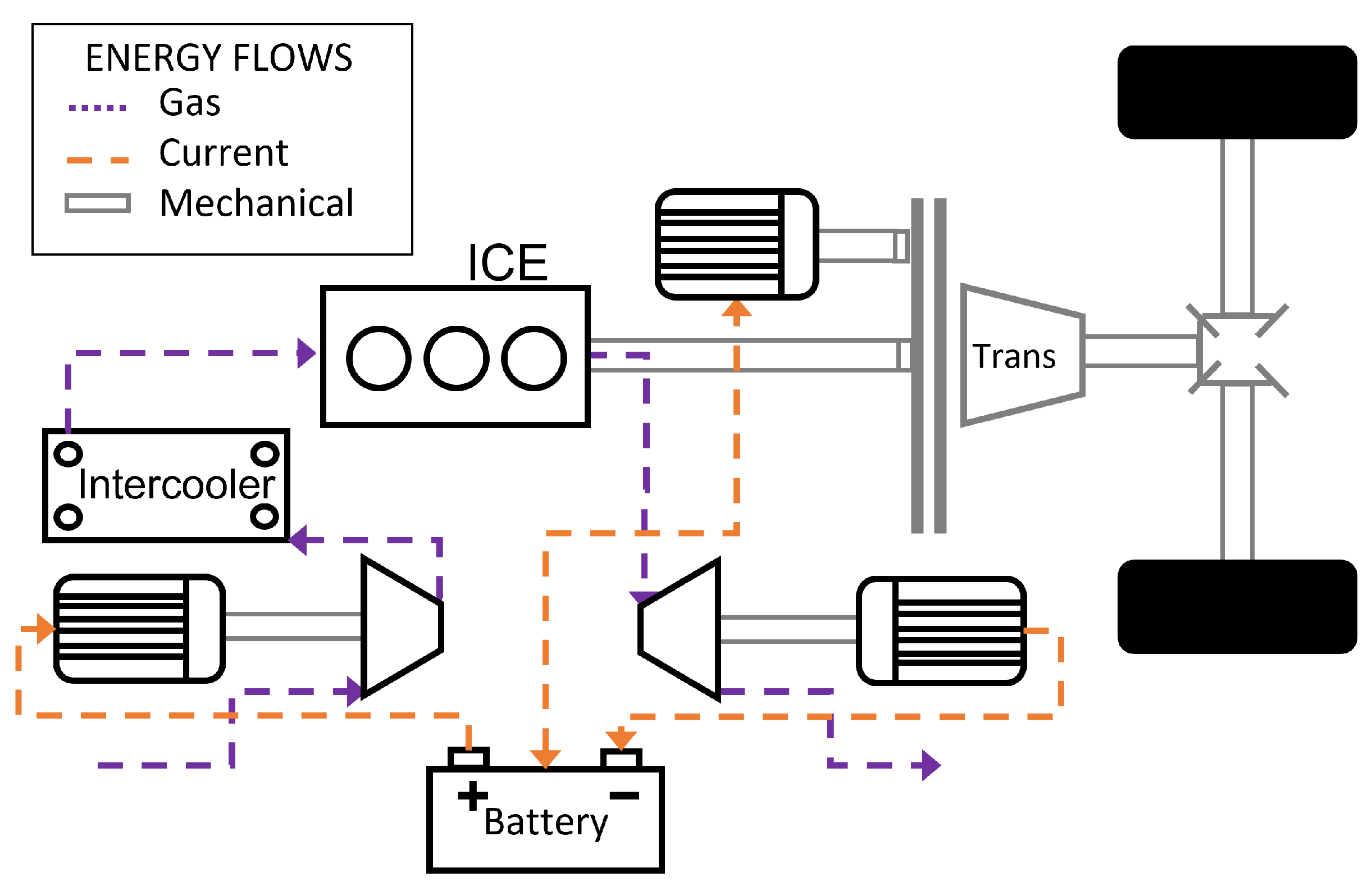
As already mentioned, the aim of the presented GT-Power model is to assess the potential of mechanically decoupling the compressor and turbine, in the pursuit of optimizing their operation. In the proposed turbo-compound engine, the engine is supercharged by an electrically driven compressor, while the energy of the exhaust gas is recovered by means of a turbine/generator group. Moreover, the system is conceived so that the energy recovered by the turbine/generator group is then stored in a battery to be conveniently used for traction, by the main propulsion machine, see
Figure 2.
Therefore, this section presents the results of the analysis conducted for the proposed turbo-compounding system.
The most straightforward control strategy for such a system would be aimed at maximizing energy recovery in the turbine by allowing unrestricted gas flow, while controlling the compressor similarly to a standard turbocharged system. Under this assumption, outputs from the turbocharged system simulations, such as the compressor and turbine speeds, can be utilized as inputs for the turbo-compound model, thus eliminating the need for a more complex optimization process to determine the desired intake pressure for the engine. Clearly, there would be a benefit in optimally controlling both turbine and compressor speeds, but since the scope of this analysis is to propose a preliminary energy evaluation, this choice has been made to allow for a direct comparison between the turbo-compounded and the turbo-charged systems.
As mentioned above, in
Section 4, the GT-Power model is modified by removing the shaft element between turbine and compressor and setting the waste-gate diameter parameter to zero, so as to simulate full mass flow admission to the turbine with no bypass.
Considering the extensive simulation time required by the model, in order to better appreciate the benefits of the new powertrain architecture, a driving cycle demanding a higher average power, such as the EPA HWY cycle was chosen [
25], whose speed profile is shown in
Figure 17 for the first 200 s of this cycle that have been simulated. The torque demand needed to accomplish this cycle portion has been evaluated in Matlab and fed to both the GT-Power models as a target input.
Figure 18 shows the energy difference versus time for turbine output and compressor input. Due to the assumptions described above, the energy consumption of the compressor is the same as for the turbocharged system dynamic simulation, while the turbine energy output at the end of the cycle increases by roughly 6.8 kJ. Indeed, the instantaneous extra power generated by the turbine during the test cycle increases up to 0.24 kW, coherent with similar results obtained during steady-state simulations in other studies [
15].
Figure 19 shows the instantaneous IMEP720 comparison between turbo-compounded and turbocharged systems. It is clear that the total admission of the exhaust gas in the turbine generates a back-pressure which increases the pumping work and decreases the engine performance. Provided that, in the real system, every pumping power increase due to the increased back-pressure related to the turbine’s full admission may be compensated by the torque assistance provided by the mild-hybrid traction motor, notwithstanding that this figure shows that the overall additional energy lost in the pumping cycle is negligible with respect to both the amount of energy generated by the turbo compound and the engine in the 200 s of the test cycle. In order to quantify this effect, we can observe that the maximum instantaneous amount of back-pressure increase assessed in the numerical simulation was equal to 8 kPa. Authors in [
15], who adopt a similar architecture, show an increment in the back-pressure up to 30 kPa between full admission and partial admission in the turbine (obtained in steady state simulations). In [
10], the authors measured an increment equal to 23 kPa due to the presence of a heat exchanger used to preheat the fluid entering the turbine, which is missing in our solution. Therefore, in our case study, the pressure increase is lower than that obtained through other configurations.
Table 5 resumes the main differences between the two systems in terms of energy: the overall engine energy output decreases by 0.18% while the total powertrain output, which is the engine output and the turbine-compressor net output, increases by 0.60%. This is due to the 60.57% increase in energy recovered from the exhaust gasses in the turbine.
These results show that turbo-compounding leads already to an improvement to the overall powertrain efficiency even without optimizing the turbine speed. In the presented 200 s simulation, the increase in terms of powertrain output leads to more energy stored in the battery, which could allow for lower fuel consumption later in the driving cycle.
Further improvements in the exhaust gas energy recovery system can be achieved by optimizing the turbine rotational speed to increase its efficiency. An attempt was made to limit the minimum turbine speed to 45,000 rpm and simultaneously decrease the instantaneous speed by 3000 rpm compared to the compressor as shown in
Figure 20. Despite the fact that this is a simple and clearly suboptimal choice, an increase of 1.7% in the energy recovered by the turbine was still obtained, due to the increased efficiency caused by the tailored speed (
Figure 21).
Table 6 shows the performance improvement of the optimized turbine speed with respect to the tubo-compound system without speed variation between turbine and compressor. These results clearly show that there is room for improvement if both turbine and compressor angular velocities are optimized to maximize the efficiency of the system.
8. Conclusions
In this study, the potential of a turbo-compounded system for a 999 cc spark-ignition engine has been preliminarily assessed. In order to achieve this objective, an experimental campaign has been initially carried out to test the engine on a dynamometer, both in steady-state and dynamic conditions. Data derived from this activity have been used to build up a GT-Power model of the engine, calibrated by means of the stationary points and further validated through data obtained in the dynamic tests. Afterwards, the performance of the turbo-compound system has been numerically assessed.
Even without a specific optimization on the intake pressure and compressor speed, some potential for energy recovery in the turbine is observed by allowing full exhaust gas flow. A 60.57% increase in the energy recovered from the exhaust gas enables the powertrain to generate an overall energy gain of 0.60%, considering the reduced engine output due to the pumping work. Moreover, based on the turbine performance, an attempt has been made to decrease its rotational speed by a constant offset of 3000 rpm with respect to the compressor speed, while setting a lower threshold of 45,000 rpm. These adjustments allowed for a 1.7% increase in recovered energy, demonstrating that the system has potential for substantial improvements if a more precise optimization procedure is applied. In fact, it is worth pointing out that, despite the obtained 0.026% increase in the powertrain energy may appear moderate, it is achieved with no other effort than a slight modification the control strategy of the turbine. Therefore, future analysis will be aimed at improving the potential of the model to study different operating conditions. In particular, adopting a predictive combustion model could allow for studies on the optimization of the intake pressure. Also, the implementation of an optimal algorithm for the control of both turbine and compressor speeds is a promising step for further improvements of powertrain efficiency.

 ,
, 


