Article

Research on Gravity Energy Saving Reconstruction Technology of Circulating Cooling Water in Mechanical Ventilation Cooling Tower of a Steel Plant

1
Chongqing Iron & Steel Company Limited, Chongqing 401220, China
2
Key Laboratory of Low-Grade Energy Utilization Technologies and Systems, Chongqing University, Ministry of Education, Chongqing 400030, China
3
School of Energy and Power Engineering, Chongqing University, Chongqing 400030, China
*
Authors to whom correspondence should be addressed.
Energies 2023, 16(17), 6274; https://doi.org/10.3390/en16176274
Submission received: 20 July 2023 / Revised: 16 August 2023 / Accepted: 24 August 2023 / Published: 29 August 2023
(This article belongs to the Special Issue Advanced Heat Transfer and Energy Saving Technology)

Abstract

:
There is a height drop in the rain area of the circulating cooling water in mechanical ventilation circulating cooling towers, resulting in the ineffective use of gravitational potential energy. High-level water collection is an effective way to reduce the energy consumption of the cooling tower. Based on this, aiming to solve the gravity energy waste problem of circulating water in the cooling tower of a steel plant, this paper innovatively puts forward the high-level water tank to utilize the energy-saving transformation technology of turbine power generation and pump power saving. Additionally, this paper explores the energy-saving effects of the two methods under different height drops. The results show that the maximum utilizable rain area height of the cooling tower is 5 m, while the annual electric energy output of turbine technology can reach 4.704 million kW·h. The high water collection technology can reduce pump power consumption and save up to 7.35 million kW·h per year of electric energy, maintaining a more significant energy-saving ability compared with the turbine power generation technology. In terms of performance, the design of a high-level water tank is to help eliminate rain areas and improve the heat exchange efficiency of water and gas, so that the water temperature of the outgoing tower is 0.13 °C lower than that of the conventional cooling tower. Meanwhile, the ventilation resistance in the rain area is weakened, the resistance coefficient can be reduced by about 40–50%, and the noise can be reduced by about 10 dB (A) under the action of the water collection device. According to the economic evaluation, the total cost of turbine power generation technology is 0.563 million dollars and the total cost of high-level water collection technology is 0.446 million dollars. The cost can be realized within two years, but the high-level water collection technology avoids additional pump maintenance costs and has better economy. This study provides a theoretical basis for the transformation and optimization design of mechanical ventilation cooling towers, and has important reference value.

1. Introduction

Nowadays, natural ventilation cooling towers or conventional mechanical ventilation cooling towers are still the main cooling methods for circulating water in large thermal power plants, so as to ensure the stable operation of each piece of heat exchange equipment in the generator set [1,2,3,4,5]. However, natural ventilation cooling towers require a larger footprint and have higher requirements for infrastructure construction and investment, which limits their further development. Due to the input of a large amount of mechanical ventilation equipment, the mechanical ventilation cooling tower usually has the disadvantages of large power consumption and greater noise, although the heat exchange performance is improved [6,7,8,9]. In recent years, high-level water collection technology based on natural ventilation or mechanical ventilation has been a concern of scholars. The high-level water collection device is installed on the base of conventional cooling towers. It directly collects circulating water flowing through the packing so as to reduce noise and save pump power, thus achieving the effects of energy saving and noise reduction [10,11,12]. In this regard, predecessors have studied the benefits of high-level water collection technology in noise control and cost control, and found that reasonable high-level water collection tanks can effectively control noise and greatly reduce power plant operating costs [13,14,15].
Among them, Fan et al. [16] studied the cooling effect of the high-level water collection device under natural ventilation, and concluded that the air resistance of the high-level water collection is reduced, which helps to increase the rapid flow of air and promotes the cooling effect. Ma et al. [17] found that the problem of super-large conventional countercurrent cooling towers lies in their high head, which makes the circulating pump consume a lot of electric energy, and the system requires large operation and maintenance costs. They point out that reducing energy consumption and noise are key issues that need to be solved. Yu et al. [18] studied the application of a high-level water collection cooling tower in Wanzhou power plant in Chongqing, and concluded that the high-level water collection tank helps to reduce the operation costs of the power plant and that the static head, under reasonable installation, can be reduced by 40%, and the heat exchange efficiency between water and gas can be significantly improved, thus controlling the noise in the rain area. Wang et al. [19] conducted a study on the cooling tower of a 1000 MW coal-fired power plant, focusing on the comparison of energy saving and noise control of conventional cooling towers and high cooling towers, and concluded that the elimination of the rain zone is key in saving energy, while avoiding the noise generated by the energy of the rain zone. Zou et al. [20] further studied the relevant technologies of high cooling towers, focusing on the analysis of high cooling towers from an economic point of view, and found that high cooling towers can significantly reduce the cost of electricity. Additionally, the investment cost is low, with significant economic benefits.
In summary, the current natural ventilation cooling tower or mechanical ventilation cooling tower has two main deficiencies. One is that the height drops of the rain area waste gravity energy, and the other is that the existence of the area is also noise interference. It is necessary to use a high-level tank and other devices to avoid the waste of gravity energy in circulating water, and to reduce the noise pollution of the cooling tower [21]. Therefore, this paper first puts forward the use of turbine power generation technology, turning the gravity energy into electricity output, and provides a design for high-level water collection technology, to use gravity energy to reduce pump energy consumption, so as to achieve the purposes of energy saving and noise reduction. This study has important reference value for the conversion of the gravity energy in circulating water in cooling towers and the transformation of energy-saving technology.

2. Research Object

The research object of this paper is selected from six concrete square cooling towers of Chongqing Iron & Steel Company Limited. The relevant data are obtained according to the operation of the cooling tower and the field investigation, which is real and credible. There are six concrete square mechanical ventilation cooling towers in the steel plant. Figure 1 is a structure diagram of the cooling tower, and Table 1 is the relevant parameters of the cooling tower. The six cooling towers are set in a unit system, supplying cooling water to the condenser, air cooler, oil cooler and other equipment of the generator set, and the cooling tower is operated 24 h a day and all the year round. The cooling tower involves the cooling fan and circulating pump motor load, of which the cooling fan load is 45 kW and the circulating pump motor load is 355 kW. The filler is made of S-wave blue raw material, which is lightweight, has a strong anti-aging ability and anti-ultraviolet ability, runs for a long time at a low temperature of −35 °C and at a high temperature of 65 °C, and possesses other advantages. Among them, the rated cooling temperature differential in the cooling tower is 7 °C. The cooling water flow of the 1# circulating cooling tower is 14,000 m3/h, the cooling water flow of the 2#, 3#, 5#, 6# circulating cooling towers is 7000 m3/h, and the cooling water flow of the 4# circulating cooling tower is 16,000 m3/h. Therefore, when operating under rated conditions, the circulating cooling water flow of a steel plant can reach 58,000 m3/h, according to the actual operation of a steel plant, while the cooling water flow of a single cooling tower is about 9000 m3/h, and the actual circulating cooling water flow of six cooling towers is about 54,000 m3/h.
The calculation parameters of cooling towers are shown in Table 2, in which the cooling water flow Q of a single tower group is 9000 m3/h, and the number of cooling towers is six. Due to the different loads of different cooling towers, the average value is used to calculate according to the research of steel plants, and the total cooling water flow Q is 54,000 m3/h, that is, q = 15 m3/s. According to the structural parameters of the cooling tower, the cooling tower has a total height of 13.25 m, in which the influent height of the cooling water is 8 m, the total thickness of the packing is controlled at 1.5 m, and the height of the rain area is left at 6.5 m, and the wasted gravity energy per second is calculated accordingly.
The calculation results of gravity energy are shown in Table 3. The gravity energy wasted per second is 955.50 kW and it runs for 8000 h a year, consuming 7.644 million kW·h of electric energy, accounting for 0.083 dollars/kW·h of industrial electricity price, and the annual electricity consumption is as high as 0.64 million dollars. Obviously, from the perspective of energy consumption, gravity energy has not been effectively used, resulting in a large amount of energy loss, which is not conducive to the purpose of green low-carbon energy saving. From an economic point of view, it increases the cost of electricity for enterprises. Therefore, it is necessary to optimize the cooling tower to avoid a large amount of energy loss and increased electricity costs.

3. Reconstruction Technology and Method

3.1. Turbine Power Generation Technology (Method 1)

As shown in Figure 2, a technical method for real-time online recovery of circulating water potential energy is proposed, thereby reducing plant power consumption and increasing power generation. Specific principle: under the premise of not affecting the operation process, in the new cooling tower collection tank, a large amount of circulating water from the top down of the cooling water tower is collected by the collection tank into the water turbine inlet, promoting the water turbine’s rotation work through the water outlet back to the pool for recycling. Among them, the turbine rotor drives the power generation device to rotate 380 V AC, which can be used for low-voltage high-power equipment, such as circulating pumps to supply power, thereby reducing self-consumption and increasing on-net electricity. In addition, the turbine is set by a bypass pipeline, such as during the maintenance of the turbine, the circulating water enters the pool through the bypass, which does not affect the normal operation of the cooling tower. According to the calculation of the parameters in Table 2 above, considering the installation of the turbine equipment, the height of the gravity energy that can be effectively used is maintained at about 5 m. Power generation is calculated as follows:
P = η ρ g Q H
In the formula, Q is the cooling water flow, H is the height difference, η is the overall efficiency (small and medium-sized turbine power generation efficiency of 75% to 85%), select the turbine efficiency of 80% for accounting.

3.1.1. Power Generation Accounting

In order to study the conversion effect of gravitational potential energy under different conditions, a turbine power generation scheme with different water level height drop is designed, and the head heights of water level drops H1, H2, H3, H4 and H5 are, respectively, controlled to be 1 m, 2 m, 3 m, 4 m and 5 m. As shown in Table 4, the power generation and generating capacity under different head heights. When the turbine head heights are 1 m, 2 m, 3 m, 4 m and 5 m, the corresponding power is 117.6 kW, 235.2 kW, 352.8 kW, 470.4 kW and 588 kW, respectively. The annual calculation is based on the operation of 8000 h, and the corresponding power generation is 0.94 million kW·h, 1.88 million kW·h, 2.82 million kW·h, 3.76 million kW·h and 4.70 million kW·h, respectively. Obviously, with the use of turbine power generation technology, gravity energy conversion of electricity is very considerable, and so is conducive to the realization of energy savings.

3.1.2. Electricity Saving

In order to evaluate the economic benefits of the turbine more directly, the cost of electricity is calculated. Using 0.083 dollars/kW·h of industrial electricity for the electricity charge calculation, as shown in Table 5, when the water head height is 1 m, 2 m, 3 m, 4 m and 5 m, the corresponding electricity cost savings are 0.078 million dollars, 0.158 million dollars, 0.236 million dollars, 0.315 million dollars and 0.393 million dollars, respectively. Therefore, turbine power generation has been a good use of gravity energy, with better economic benefits.

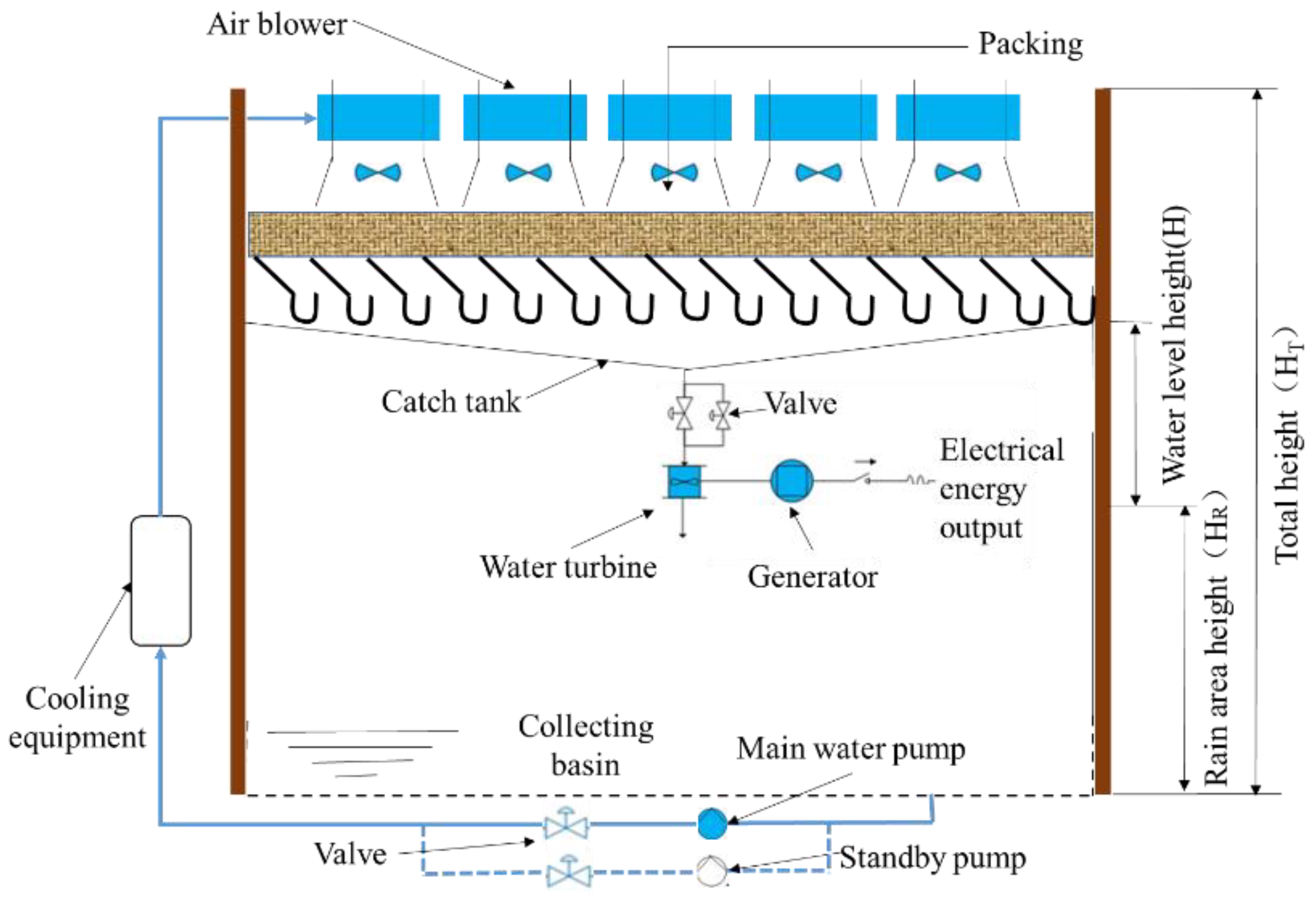
3.2. High Water Collection Technology (Method 2)

In view of the energy-saving effect of high water collection technology, the gravity energy lost in the rain area can be fully saved. However, a steel plant currently uses a concrete square mechanical ventilation cooling tower. Replacing it with a high cooling tower is not in line with the actual situation, and will increase a lot of capital investment. Therefore, based on the structure of the mechanical ventilation cooling tower, building a high-level water tank at the lower end of the packing of the conventional cooling tower is proposed. As shown in Figure 3, the specific working principle is under the premise of not affecting the operation process, the new high level water collection tank is installed, result in cooling tower from the top down a large amount of circulating water collected by the high level water collection tank, and the water pump will be sent to the heat exchange equipment. After full heat exchange it will be returned to the pool for recycling. The high level water tank pressure is used to reduce the power loss of the pump, so as to achieve the purpose of energy saving.
The formula that is used to calculate the gravity energy that can be saved per second, and the pump power that can be saved, is as follows:
W = m g h = ρ V g h
P = W η
In the formula, W represents the gravitational potential energy per unit time, that is, the effective power of the pump, P is the input power of the pump, η is the working efficiency of the pump (generally about 75–85%), and 80% is selected in this paper.

3.2.1. Electric Energy Saving

As shown in Table 6, the pump power and energy savings at different high sink heights are shown. When the height of the sink is 1 m, 2 m, 3 m, 4 m, 5 m, the corresponding power is 184 kW, 368 kW, 551 kW, 735 kW, and 919 kW. When the height of the upper water tank is 1 m, 2 m, 3 m, 4 m and 5 m, the corresponding power saving is 1.47 million kW·h, 2.94 million kW·h, 4.41 million kW·h, 5.88 million kW·h and 7.35 million kW·h, respectively. Therefore, the use of a high water tank can effectively avoid gravity energy waste and save electric energy.

3.2.2. Electricity Cost Saving

Table 7 shows the electricity cost savings under different sink heights. The electricity cost calculation is carried out using 0.083 dollars/kW·h for industrial electricity consumption. When the height of the high sink is 1 m, 2 m, 3 m, 4 m and 5 m, the corresponding electricity cost savings are 0.123 million dollars, 0.246 million dollars, 0.369 million dollars and 0.492 million dollars, 0.615 million dollars, respectively. Obviously, the use of a high sink design is conducive to saving the power consumption of the pump.

3.3. Performance Analysis of High-Level Tank

3.3.1. Cooling Performance

According to relevant literature reports [22], the intensity of the cooling load of each part of the mechanical ventilation cooling tower in the total cooling load is as follows: 10% in the water distribution area, 20% in the conventional rain area and 70% in the filling area. Accordingly, the calculation of the mechanical ventilation cooling tower before the transformation is carried out:
m = ρ V = 10 3 × 9000 = 9 × 10 6   k g
T a = T i n T o u t = 42 33 = 9   ° C
Q a = m c T a = 9 × 10 6 × 4200 × 9 = 3.4 × 10 8   kJ
In the formula, ρ is the density of cooling water, V is the volume of cooling water per hour, T i n is the temperature of cooling water entering the tower, T o u t is the temperature of cooling water exiting the tower, and c is the specific heat capacity of cooling water.
Heat transfer in water distribution area:
Q a 1 = Q × 10 % = 3.4 × 10 7   kJ
Heat transfer in conventional rain areas:
Q a 2 = Q × 20 % = 6.8 × 10 7   kJ
T r a i n = Q b m c = 6.8 × 10 7   k J 9 × 10 6 × 4200 = 1.79   ° C
Then, the temperature into the packing:
T p a c k = T i n T r a i n = 42 1.79 = 40.21   ° C
Heat transfer in packing area:
Q a 3 = Q × 70 % = 2.38 × 10 8   kJ
However, the packing area of the modified mechanical ventilation cooling tower takes on more air–water heat exchange, accounting for 90.5% of the heat exchange in the packing area, which is significantly higher than the 65~75% of the conventional mechanical ventilation cooling tower. Additionally, the heat exchange performance is about 28.5% higher than it was before the transformation [23]. To this end, the accounting for the reformed cooling tower is as follows:
Heat transfer in water distribution area:
Q b 1 = Q a 1 = Q × 10 % = 3.4 × 10 7   kJ
Heat transfer in light rain area:
ε = H b H a = 0.5 6.5 = 7.69 %
Q b 2 = Q a 2 × ε = Q × 20 % × ε = 0.52 × 10 7   kJ
T r a i n = Q b m c = 0.52 × 10 7 k J 9 × 10 6 × 4200 = 0.14   ° C
Then, the temperature into the packing:
T p a c k = T i n T r a i n = 42 0.14 = 41.86   ° C
In the formula, H a is the height of the rain area before the transformation, that is, 6.5 m, and H b is the height of the rain area after the transformation, that is, 0.5 m.
Q b 3 = Q a 3 × ( 1 + 28.5 % ) = Q × 70 % × ( 1 + 28.5 % ) = 3.06 × 10 8   kJ
Q b = Q b 1 + Q b 2 + Q b 3 = 3.45 × 10 8   kJ
T b = Q b m c = 3.56 × 10 8   k J 9 × 10 6 × 4200 = 9.13   ° C
T o u t = T i n T b = 42 9.41 = 32.87   ° C
Obviously, the setting of the high water tank reduces the height of the rain zone. The temperature of the cooling tower is reduced by 0.13 °C and the heat transfer performance is not only without decrease, but slightly increases.

3.3.2. Resistance Property

Relevant studies have found that the resistance in the rain area of conventional towers is usually more than 40%, and the resistance in the rain area of tall towers is about 25% compared with conventional towers. Li et al. [24] calculated the resistance coefficient of the high cooling tower by combining experimental measurements and found that it was about 40–50% lower than that of the conventional tower. Guo et al. [25] found that the total resistance coefficient of the high tower is about 53.89, which is only 58% of the total resistance coefficient of the conventional tower. Therefore, thanks to the setting of the high sink, the air inlet at the center of the cooling tower is more uniform, which can improve the cooling effect [26]. The elimination of the rain zone greatly reduces the air inlet resistance within the range of the cooling tower inlet, and the high sink makes the rain zone of the tower short, which can reduce the ventilation resistance in the rain zone, and the resistance coefficient can be reduced by about 40–50%.

3.3.3. Noise Reduction Performance

Relevant studies have shown [25] that the noise of large mechanical ventilation cooling towers is close to 82–86 dB (A), and when the height of the rain zone is reduced to within 26.5% of the rain zone of conventional cooling towers, the noise reduction can reach 10~15 dB (A). According to the research of Zou et al. [19], the noise of conventional cooling towers is close to 86~88 dB (A), and the free fall height of the high-level water collection tower is about 25% of the fall height of the conventional cooling tower, and the noise can be reduced by about 8~10 dB (A). The rain zone height of the cooling tower of a steel plant in this paper is about 6.5 m, and the rain zone height after the transformation is 0.5 m, which is only 7.69% of the rain zone height of the conventional mechanical ventilation cooling tower. The rain zone has the diversion effect of the water collection device and the buffer effect of the bottom pool, and the noise is expected to be reduced within 10 dB (A).

4. Investment Cost Budget

4.1. One-Time Investment

The one-time investment cost mainly includes the construction of the water tank, the civil construction cost of the generator and the suction well, and also includes the cost of the hydro generator, the water pump, the electrical equipment, and the supporting pipeline facilities. In addition, it also includes the human installation cost of the construction process, for the six cooling towers of a steel plant, the total investment cost of method 1 is 0.563 million dollars, and the total cost of method 2 is 0.446 million dollars.

4.2. Operation and Maintenance Investment

In order to ensure safe and economic operation, supporting mechanical and electrical equipment, such as a hydraulic turbine governor, an oil pressure device, excitation equipment, low-voltage switches, and automated operation and protection systems should be maintained, as well as depreciation and maintenance costs, human resources costs, etc. Method 1 requires a maintenance cost of 0.014 million dollars, while method 2 is based on the pump transformation, and will not add additional costs on this basis. In contrast, the use of turbine power generation technology requires higher maintenance costs, and high water collection technology does not add additional costs.

4.3. Investment Return Cycle

As shown in Table 8, for six cooling towers in a steel plant, the total investment cost of method 1 is 0.563 million dollars, and the total cost of method 2 is 0.446 million dollars. When the height of the water level drop is 4–5 m, the industrial electricity price is used to calculate, and profit can be achieved in one year; At feed-in tariffs, it can still be profitable within two years. From a long-term perspective, method 2 avoids additional maintenance costs for the pump and has better economics.

5. Conclusions

In order to solve the problem of gravity energy waste when circulating cooling water in the mechanical ventilation cooling towers of a steel plant, this paper proposes the use of turbine power generation technology and high water collection technology to save energy. For achieving the purpose of energy conservation, through the specific energy-saving technology transformation design, the main conclusions are as follows:
(1)
The gravity energy wasted by a steel plant cooling is 955.50 kW per second, and the annual energy consumption reaches 7.64 million kW·h. The annual electricity cost is 0.64 million dollars based on the industrial electricity price of 0.083 dollars/kW·h.
(2)
The use of turbine power generation technology and high water collection technology is conducive to the conversion of gravity energy, and the energy saving amount increases with the increase of water head height. When the height of the rain area used is 5 m, the annual energy of the turbine power generation and the high water collection belt reach 4.70 million kW·h and 7.35 million kW·h, respectively, thus the high water collection technology has more significant energy saving potential.
(3)
With the help of turbine power generation technology and a high water collection high water tank design, it is helpful to eliminate rain areas and improve the efficiency of water–gas heat exchange, so that the water temperature of the tower is reduced by 0.13 °C, compared with the conventional cooling tower. Meanwhile, the ventilation resistance in the rain area is weakened, the resistance coefficient can be reduced by about 40–50%, and the noise can be reduced within 10 dB (A) under the diversion of the water collection device.
(4)
For six concrete square mechanical ventilation and cooling towers in a steel plant, the total investment cost of turbine power generation technology is 0.563 million dollars and the total cost of high water collection technology is 0.446 million dollars, for the rational use of gravity energy in circulating cooling water. The investment payback period is within two years.
There is waste of gravity energy of circulating cooling water in large cooling towers of steel plants, power plants and other industrial equipment, which has not been effectively converted and utilized at present. The main research direction in the future is to convert it into electrical energy or use its water pressure to reduce pump power consumption.

Author Contributions

Conceptualization, C.T.; methodology, C.Z.; software, C.Z.; validation, C.T.; formal analysis, Y.W.; investigation, Y.Y.; resources, F.Z.; data curation, D.H.; writing—original draft preparation, C.Z.; writing—review and editing, C.Z.; visualization, Y.W.; supervision, Z.Y.; project administration, F.Z.; funding acquisition, C.T. All authors have read and agreed to the published version of the manuscript.

Funding

This research received no external funding.

Data Availability Statement

No new data were created or analyzed in this study. Data sharing is not applicable to this article.

Conflicts of Interest

The authors declare no conflict of interest.

References

  1. Berman, L.D. Evaporative Cooling of Circulating Water; Pergamon Press: Oxford, UK, 1961; Volume 392, p. 140. [Google Scholar]
  2. Jorge, F.; Armando, C.O. Thermal behaviour of closed wet cooling towers for use with chilled ceilings. Appl. Therm. Eng. 2000, 20, 1225–1236. [Google Scholar]
  3. Shi, G.; Ting, M.; Zhang, H. Performance analysis of a mechanical-draft counter-flow wet cooling tower with thermosiphon. J. Eng. Therm. Energy Power 2020, 35, 61–69. [Google Scholar]
  4. Niu, R.; Li, L.-M.; Wen, X.-Y.; Li, B.-K. Numerical Simulation of Counter Flow Natural Draft Wet Cooling Tower with Flue Gas Injection. J. Northeast. Univ. (Nat. Sci.) 2017, 38, 819–822. [Google Scholar]
  5. Xie, M.; Zhao, S. Numerical simulation of the flow field inside air duct of mechanical draft cooling tower. J. China Inst. Water Resour. Hydropower Res. 2018, 16, 227–232. [Google Scholar]
  6. Zeng, S.; Lv, X.; Lv, C.; Luo, H. Research on Noise Abatement Schemes of Mechanical Ventilation Cooling Tower Groups in the Gas Turbine Power Plant. South. Energy Constr. 2021, 8, 73–78. [Google Scholar]
  7. Wang, W.; Zheng, H.; Li, Z.; Zhen, L.; Zhao, P.F.; Chen, G.; Yuan, P.; Yan-Li, L. Design procedure of condensing and defogging water collecting device for mechanical ventilation cooling tower. Sci. Technol. Eng. 2019, 19, 141–146. [Google Scholar]
  8. Chang, L.; Li, L.; Li, H. Research on Hot Moist Air Reflow of Forced Draft Cooling Tower. Nucl. Power Eng. 2017, 38, 32–35. [Google Scholar]
  9. Varela-Boydo, C.A.; Moya, S.L.; Watkins, R. Study of wind towers with different funnels attached to increase natural ventilation in an underground building. Front. Archit. Res. 2020, 9, 925–939. [Google Scholar] [CrossRef]
  10. Lv, D.; Sun, F.; Zhao, Y.; Gao, M.; Zhang, X. Research on the Air Flow Field Inside the Water Collecting Devices of the Cooling Tower with the WCDs. Proc. CSEE 2020, 49, 77–82. [Google Scholar]
  11. Wang, M.; Wang, J.; Yang, X. Numerical Simulation Study on Cooling Performance of Operating Condition for High-level Water Collecting Cooling Tower. Proc. CSEE 2019, 39, 1723–1731+1869. [Google Scholar]
  12. Nasrabadi, M.; Finn, D.P. Performance analysis of a low approach low temperature direct cooling tower for high-temperature building cooling systems. Energy Build. 2014, 84, 674–689. [Google Scholar] [CrossRef]
  13. Jia, M.; Hu, S.; Han, L. Thermal Performance Study of a High-level Water Collecting Cooling Tower for 1000 MW Units. J. Chin. Soc. Power Eng. 2017, 37, 751–756+772. [Google Scholar]
  14. Fan, J.-Y.; Liu, J.; Wang, C.-Y. Performance Analysis of high-level Water Collecting Cooling Tower. Turbine Technol. 2021, 63, 25–28. [Google Scholar]
  15. Nasrabadi, M.; Finn, D.P. Mathematical modeling of a low temperature low approach direct cooling tower for the provision of high temperature chilled water for conditioning of building spaces. Appl. Therm. Eng. 2014, 64, 273–282. [Google Scholar] [CrossRef]
  16. Ma, D. Application Research on Domestic High-Level Water-Collecting Cooling Tower Technology. J. Henan Sci. Technol. 2020, 116–118. Available online: https://kns.cnki.net/kcms2/article/abstract?v=nnFo4n0nVBEQDnTov-1sb4FcU0unT1nDE1u7F0aQOYcvJEJo2tBHaUVUR50qBL27YIWpLvuQpiY--lz0TspuqmdMznU-1E_CaQZ2s97IYYup6oYF7fhYn0997tHkRyOr69udBd7MYCc=&uniplatform=NZKPT&flag=copy (accessed on 19 July 2023).
  17. Yu, P. Wanzhou power plant high water collection cooling tower application. China High-Tech 2019, 105–107. [Google Scholar] [CrossRef]
  18. Wang, Z. Research on cooling tower selection for a 1000 MW coal-fired power plant. Electromech. Inf. 2019, 31–32. [Google Scholar] [CrossRef]
  19. Zou, Y.; Yu, J. Technical research on high water receving cooling tower. Eng. J. Wuhan Univ. 2018, 51, 438–441. [Google Scholar]
  20. Long, G.; Zhang, G.; Sun, F. Numerical study on the three-dimensional thermal characteristics of mechanical draft high-level water collecting cooling tower. Proc. CSEE 2022, 1–9. [Google Scholar] [CrossRef]
  21. Navarro, P.; Ruiz, J.; Kaiser, A.S.; Lucas, M. Effect of fill length and distribution system on the thermal performance of an inverted cooling tower. Appl. Therm. Eng. 2023, 231, 120876. [Google Scholar] [CrossRef]
  22. Ma, L. Effect and Simulation of Ambient Crosswind on Cooling Performance of Natural Ventilation Countercurrent Wet High Fetch Cooling Tower. Master’s Thesis, Shanghai University of Electric Power, Shanghai, China, 2019. [Google Scholar]
  23. Sun, W. Study on Particle Size Distribution and Resistance Performance of Water Droplets in Rain Area of Natural Ventilation Countercurrent Wet Cooling Tower. Master’s Thesis, Shandong University, Jinan, China, 2019. [Google Scholar]
  24. Li, H. Three-Dimensional Numerical Simulation of High Level Water Collection Cooling Tower with Natural Ventilation. Master’s Thesis, North China Electric Power University, Beijing, China, 2017. [Google Scholar]
  25. Guo, Y.; Cheng, H.; Liu, H. Technical Study and Economic Analysis of High Water Receiving Cooling Tower. Shenhua Technol. 2018, 16, 57–60+73. [Google Scholar]
  26. Sharifullin, V.N.; Badriev, A.I. Aerodynamic Characteristics of the Cooling Tower under the Nonuniform Distribution of the Water and Air Flows. Therm. Eng. 2019, 66, 569–574. [Google Scholar] [CrossRef]
Figure 1. Schematic diagram of mechanical ventilation cooling tower in a steel plant.
Energies 16 06274 g001
Figure 2. Schematic diagram of turbine power generation technology scheme.
Energies 16 06274 g002
Figure 3. High water collection technology (height H = 5 m).
Energies 16 06274 g003
Table 1. Rated parameters of existing cooling towers in a steel plant.
Cooling Tower TypeRated Pump FlowTemperature DifferentialNumber
1# circulating cooling towerQ = 2 × 3500 m3/h△T = 7 °C2
2# circulating cooling towerQ = 2 × 3500 m3/h△T = 7 °C1
3# circulating cooling towerQ = 2 × 3500 m3/h△T = 7 °C1
4# circulating cooling towerQ = 2 × 4000 m3/h△T = 7 °C2
5# circulating cooling towerQ = 2 × 3500 m3/h△T = 7 °C1
6# circulating cooling towerQ = 2 × 3500 m3/h△T = 7 °C1
Table 2. Cooling tower accounting parameters.
Index ParameterValueUnit
Single cooling tower water flow9000m3/h
Cooling tower number6/
Cooling tower total height HT13.25m
Packing height HP1.5m
Rain area height HR6.5m
Water inlet height H in8m
Table 3. Calculation results of energy consumption.
Accounting IndexGravitational Energy LossElectrical Energy ConsumptionEconomic Loss
Value955.50 7.640.64
Unit(kW)million kW·hmillion dollars
Table 4. Calculation of power and generation at different heights.
Water Level Height (m)H1H2H3H4H5
Power (kW)117.6235.2352.8470.4588
Electric energy (million kW·h)0.941.882.823.764.70
Table 5. Calculation parameters at different heights.
Working ConditionH1H2H3H4H5
Water level height (m)12345
Electricity saving (million dollars)0.0780.1580.2360.3150.393
Table 6. Energy saving at different heights.
Water Level Height (m)H1H2H3H4H5
Pumping power (kW)184368551735919
Energy saving (million kW·h)1.472.944.415.887.35
Table 7. Electricity cost savings at different heights.
Working ConditionH1H2H3H4H5
Water level height (m)12345
Electricity cost savings (million dollars)0.1230.2460.3690.4920.615
Table 8. Electricity savings by different technologies Unit: million dollars.
Water Level Height (m)H1H2H3H4H5
Electricity loss0.640.640.640.640.64
Method 10.0780.1580.2360.3150.393
Method 20.1230.2460.3690.4920.615
Disclaimer/Publisher’s Note: The statements, opinions and data contained in all publications are solely those of the individual author(s) and contributor(s) and not of MDPI and/or the editor(s). MDPI and/or the editor(s) disclaim responsibility for any injury to people or property resulting from any ideas, methods, instructions or products referred to in the content.

