1. Introduction
Induction motors (IMs) have the advantage of a simple and reliable structure with low manufacturing and maintenance costs, but they also have two main drawbacks. Firstly, compared with permanent magnet motors (PMSMs), IMs have higher rotor loss and lower efficiency. Secondly, IMs need to absorb lagging reactive power from the grid to establish a magnetic field, resulting in a low power factor and a waste of grid capacity. In addition, IMs have a narrow range of high efficiency and power factor. Once the motor’s operating point moves away from the rated point, its efficiency and power factor drop rapidly, and power consumption increases substantially [
1].
In China, IMs account for the largest proportion of the total installed capacity of industrial motors. According to China’s National Bureau of Statistics, by the end of 2021, the installed capacity of IMs accounted for greater than 60% of the total installed capacity. Of these motors, 80% of IMs are able to meet the IE3 standard issued by the International Electrotechnical Commission (IEC), but less than 5% of the IMs are able to meet the IE4 standard. Currently, over 150 million kilowatts of IMs are installed in various industrial fields in China, with the main components being IE2 and IE3 grades. According to the standards issued by the IEC, the efficiency of IE4 motors has increased by about 2.7–3.6% compared to IE3 [
2]. So, if calculated based on an average increase of 3% in motor efficiency, upgrading existing motors can save over 50 billion kilowatt hours of electricity annually, equivalent to the annual power generation of several large power plants. From the perspective of the global market, among low-voltage AC motors, the share of premium efficiency motors that can meet the IE3 standard was only 17% in 2016, and the share of super-premium efficiency motors that can meet the IE4 standard was less than 1%. These two figures reached 23% and 1%, respectively, in 2021 [
3]. Obviously, with the promotion and application of high-efficiency motors, their share in the overall motor market is gradually increasing. However, the most effective way to improve global motor energy efficiency is to make changes to the huge inefficient motor stock market. For those inefficient induction motors below IE3 standard, minimizing remanufacturing costs and maximizing efficiency are both important considerations. Therefore, it can be seen that the research on efficiency improvement of inefficient IMs with low remanufacturing costs can help to improve social and economic benefits.
The low efficiency and power factor of IMs are derived from copper loss in the rotor and excitation component in the stator current. Compared with IMs, PMSMs have inherent performance advantages. PMSMs rotate at synchronous speed, so there is no copper loss in the rotor. Moreover, the magnetic field of a PMSM is established through the PMs so that the excitation component can be completely excluded from the stator current. Therefore, the efficiency and power factor of PMSMs are higher, while the stator current of the motor is smaller, the stator and rotor temperature rise is lower, and the motor overload capacity is stronger [
4,
5].
Obviously, replacing existing low-efficiency IMs with PMSMs is the most ideal solution. However, the main markets for existing IMs are mostly in cost-sensitive industrial fields. Therefore, it is more important to investigate how to obtain reliable efficiency improvements in IMs with the lowest possible upgrade costs.
Currently, the academic community has conducted some research on the efficiency improvement and motor remanufacturing of inefficient IMs, and the main relevant research results are as follows.
Scholars Li Zheng et al. studied the remanufacturing technology and development prospects of PMSMs, constructed a set of remanufacturing assessment systems, and analyzed the key problems in the process [
6].
Min-Seok Kim compared the motor performance of different IM rotors using different materials. In his paper, a Cu-Al composite rotor was proposed to improve the efficiency, power factor, and starting performance of the motor, enabling the IM to meet the IE4 standard [
7].
Scholar Isabelle Hofman utilized the finite-element method (FEM) to study the performance improvement after replacing an IM rotor with a PM rotor. The paper took a 1.5 kW 6-pole IM as an example, and after replacing the rotor, the efficiency of the motor was improved by 14%. On the basis of this, the article also investigated the improvement of the M235-35A material on the performance of the motor, and the efficiency of the motor was further improved by 2% by making a material substitution for the stator [
8].
Further, the scholar Ronggang Ni proposed a complete solution to realize the remanufacturing of inefficient IM drive systems by replacing the squirrel-cage rotor with a built-in PM rotor with no damping windings, which enables it to meet the IE4 standard. Moreover, this paper also studied the respective characteristics and advantages of Y and Δ winding connections after remanufacturing process [
9]. In addition, there are some studies on the method of remanufacturing IMs into self-starting PMSMs by replacing the squirrel-cage rotor with a PM rotor with a damping winding, and prototypes have been fabricated. The efficiency and power factor of the modified motor were experimentally verified to be improved [
10,
11].
High harmonics are a major factor that hinders the operational stability and limits the efficiency of all types of electrical equipment [
12,
13]. With the introduction of PMs in the rotor, an increase in harmonic fields in the air-gap magnetic field must be taken into account. These harmonics increase the core losses and PM eddy current losses in the remanufactured motor. In PMSMs, core losses and PM eddy current losses are generally reduced by optimizing the air-gap magnetic field waveform. Surface-mounted PMSMs can optimize the air-gap magnetic field waveform by optimizing the design of the PM shape or by using Halbach permanent magnet arrays [
14,
15]. The arrangement of built-in PMs is more flexible, and by changing the topology of the PMs or optimizing the structural parameters, the air gap magnetic field waveform can be optimized, thus improving the efficiency of the PMSM [
16,
17,
18,
19].
In addition to the remanufacturing of IMs into permanent magnet motors, there are also some studies on retrofitting into synchronous reluctance motors (Syn-RM). Paper [
20] is also based on the idea of rotor replacement for motor remanufacturing, but the authors proposed a PM rotor and a reluctance rotor, respectively. After replacing the rotor, both schemes are able to meet the IE4 standard. Comparing the two schemes, the maximum efficiency of the RM rotor is lower than that of the PM rotor, and the high-efficiency range of the motor is smaller than when the permanent magnet rotor is used.
Scholars Jan Barta et al. also proposed a remanufacturing method to replace the squirrel-cage rotor by using an RM rotor with a damping winding. In this paper, an optimization algorithm was used to optimize the rotor parameters so that the remanufactured motor could achieve the desired performance requirement [
21]. Huai-Cong Liu further discussed the motor design and manufacturing process of a self-starting Syn-RM that can meet the IE4 standard based on the consideration of “manufacturing process loss” [
22].
From the currently existing research results, the remanufacturing of IMs is basically realized by direct replacement of the rotor. The existing research has not yet seen the case of motor remanufacturing on the basis of preserving the original rotor, which is also the reason why the current cost of motor remanufacturing cannot be further limited. In the existing remanufacturing methods, the replaced IM rotor no longer has a utilization value. Therefore, the process of recycling, processing, scrapping, and remanufacturing this part of the material also increases the energy consumption in the entire motor industry.
Different from the existing studies, this paper proposes a low-cost permanent magnetization remanufacturing (PMR) method for IMs by direct modification of the original induction rotor so that the modified motor can meet higher energy IE standards. The specific modification method is to mill slots on the surface of the original induction rotor and embed PMs, so as to transform the IM into a surface-embedded line-start permanent magnet synchronous motor (SELS-PMSM). In order to further elaborate the related research results, this paper is organized as follows.
In
Section 2, this paper first proposes a design flow for PRM. Then, based on this design process, an IM example is remanufactured and designed, and the performance differences before and after remanufacturing are compared by the FEM.
In
Section 3, this paper studies the factors affecting the starting performance of PMR motors.
In
Section 4, this paper further studies the factors affecting the rated performance of PMR motors.
In
Section 5, this paper builds a prototype motor based on the PMR design. This paper also briefly describes the manufacturing process of the rotor and calculates the PMR cost. Finally, this paper verifies the performance improvement effect of PMR by carrying out experiments on the prototype motor.
2. An Analytical Performance Analysis for PMR Design
This article is based on the example of a real IM. The original model of the IM was Y2-132M1-6, and its rated performance parameters are shown in
Table 1.
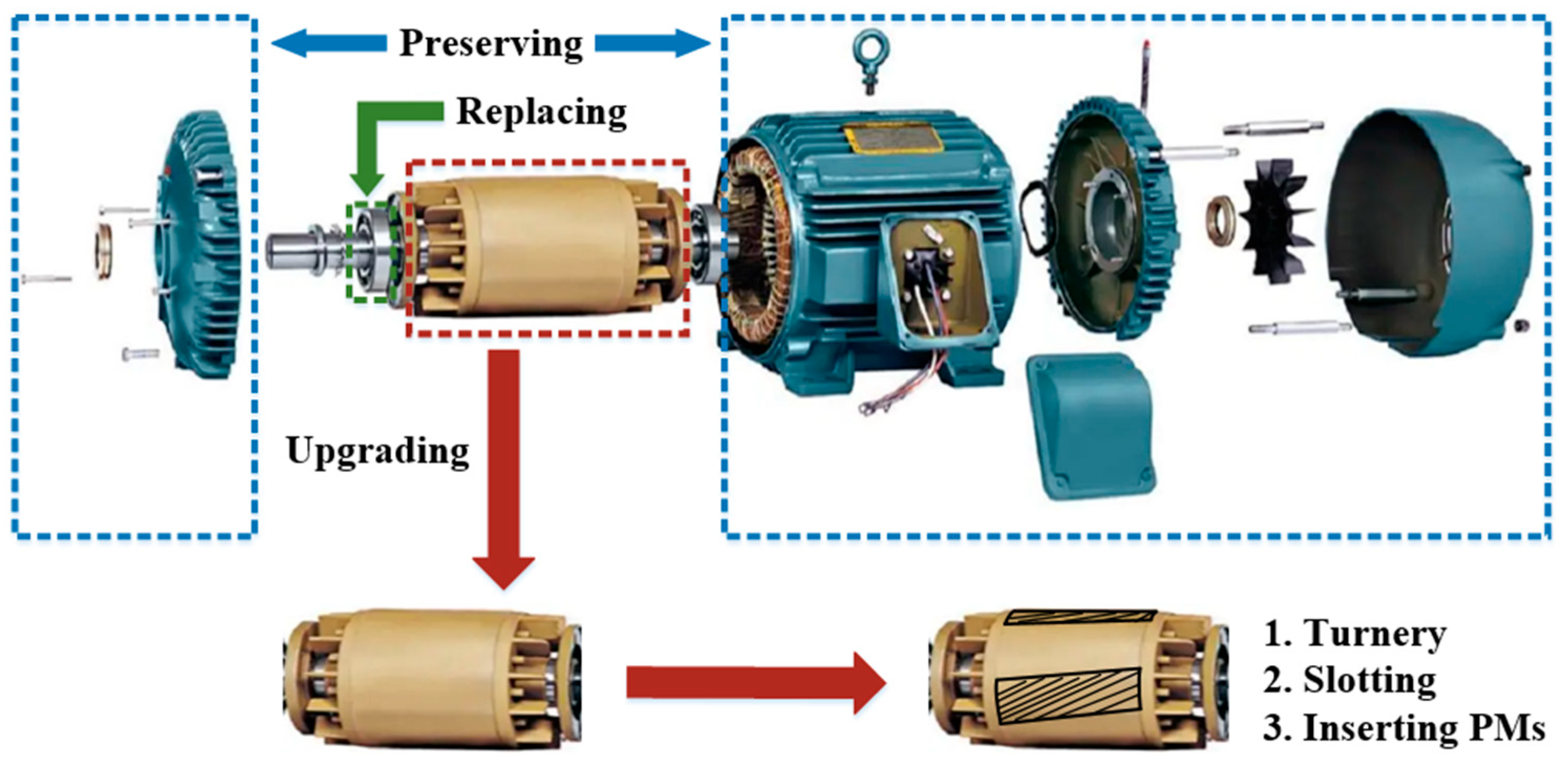
The basic PMR process is shown in
Figure 1. The motor case, stator core, and windings of the original IM were preserved. The bearings and some fittings needed to be replaced, and the original rotor core and squirrel-cage windings were upgraded on the basis of preserving them.
The core of the PMR process is rotor reprocessing, and the basic steps are as follows:
- (a)
Remove the squirrel-cage rotor from the IM.
- (b)
Uniformly turn the surface of the rotor to a certain thickness to expand the original air gap.
- (c)
According to the electromagnetic design scheme, mill grooves at the corresponding positions on the rotor surface and insert permanent magnets.
- (d)
Wrap a weft-less glass ribbon around the outer side of the rotor to fix the permanent magnet.
- (e)
Finish with rotor polishing, dynamic balance inspection, rotor installation, and motor testing.
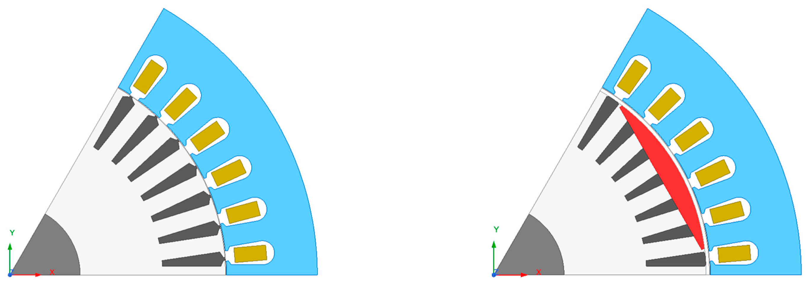
In order to reduce the excitation component in the stator current and improve the power factor of IMs, the air gap is generally designed to be very small. If the IM is directly transformed into a surface-embedded PM rotor, there will be two hidden dangers. The first is that the PM may be removed from the fixation during high-speed rotation. The second is that it may come into contact with the stator during rotation due to possible errors in assembly. To solve this problem, the original air-gap width needs to be enlarged, and necessary protection needs to be added on the outer side of the PM. The specific method is to evenly turn the rotor to a certain thickness and wrap a weft-less glass ribbon to fix the PMs.
The 2D structure of the motor before and after PMR is shown in
Figure 2.
2.1. The Process of PMR
As mentioned earlier, the PMR process will completely preserve the stator core and winding of the original IM and only reprocess the rotor from a squirrel-cage rotor to a PM rotor with damping winding. According to the theory of the line-start PMSM, the permanent magnet EMF
E0 determines the generating braking torque during the starting process and the power factor in operation, which is the key to determining the starting and rated performance of the motor. Therefore, the core of the remanufacturing design process for PMR is centered around the selection of
E0.
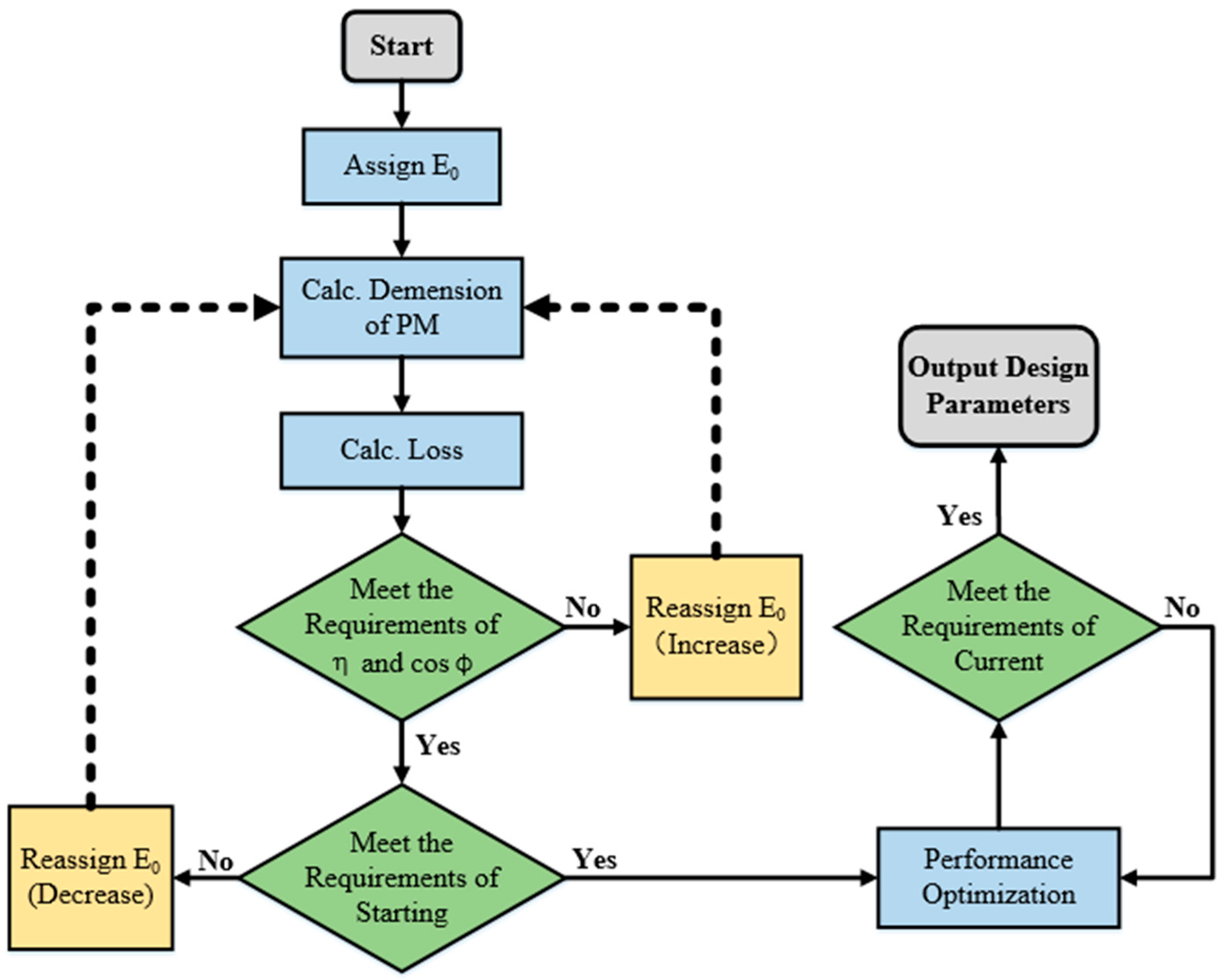
Figure 3 shows the design process for IMs followed in this paper.
Figure 3 is illustrated as follows. The core of the PMR method is the selection of
E0. Generally,
E0 is initially selected as a value slightly smaller than the supply voltage. According to the value of
E0, the initial size of the permanent magnet can be determined, and the losses, starting performance, and rated performance of the motor can be analyzed by FEM. As shown in
Figure 3, according to the design constraints of different motors for starting ability, as well as efficiency
η and power factor cos
φ,
E0 will eventually be determined as a compromise value, and then the other design parameters of the motor will be parameterized, so as to obtain the optimized final solution.
From the design flow, it can be seen that the consumption of PMs is influenced by both the starting performance requirement and the rated performance requirement of the motor. A lower usage of PMs helps to improve the starting performance of the motor, while a higher usage of PMs helps to improve the rated performance.
The magnitude of E0 determines the starting and rated performance of the motor, while the sinusoidal nature of the E0 determines the losses and efficiency of the motor after PMR. Especially for IMs with the Δ-connection of stator windings, if the air-gap magnetic field contains high amplitude 3k-order harmonics, then the harmonic EMF in the same phase will be induced in the three-phase winding, which will generate harmonic circulating currents with large amplitude, which will cause the motor to heat up and affect the efficiency of PMR. Therefore, the design of the PM shape is a key factor that must be considered advanced.
2.2. The Design of PMs
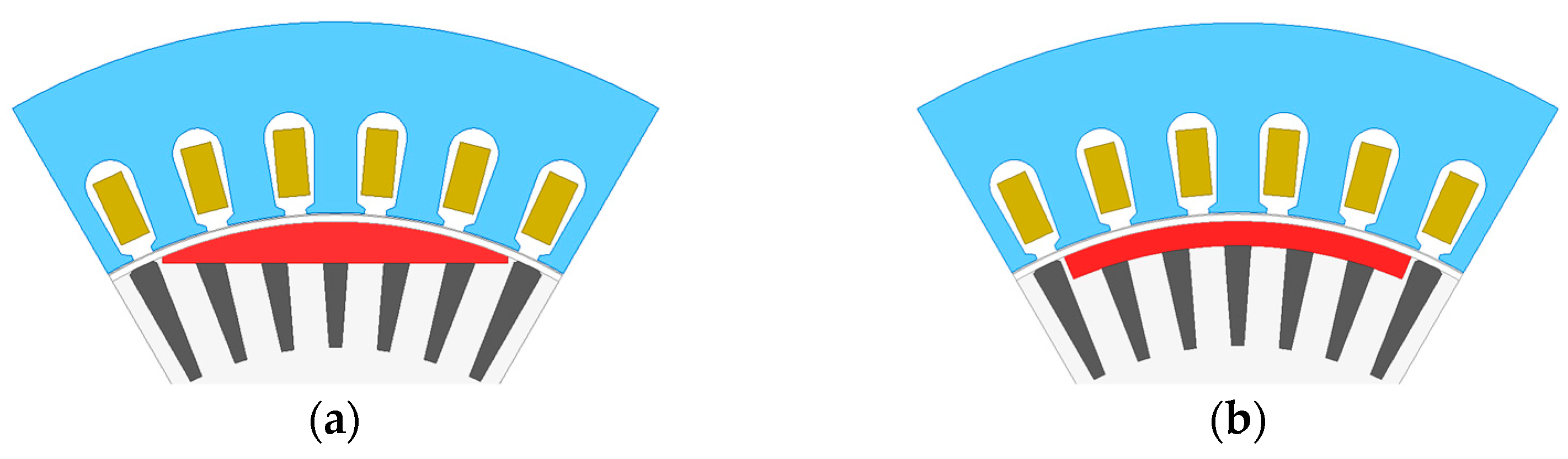
Figure 4 compares two easy-to-process surface-embedded PM shapes. The PM in
Figure 4a is sector-shaped and is magnetized in parallel. The PM in
Figure 4b is tile-shaped and uses radial magnetization. The consumption of the PMs is adjusted so that they induce the same RMS value of
E0 in the stator windings.
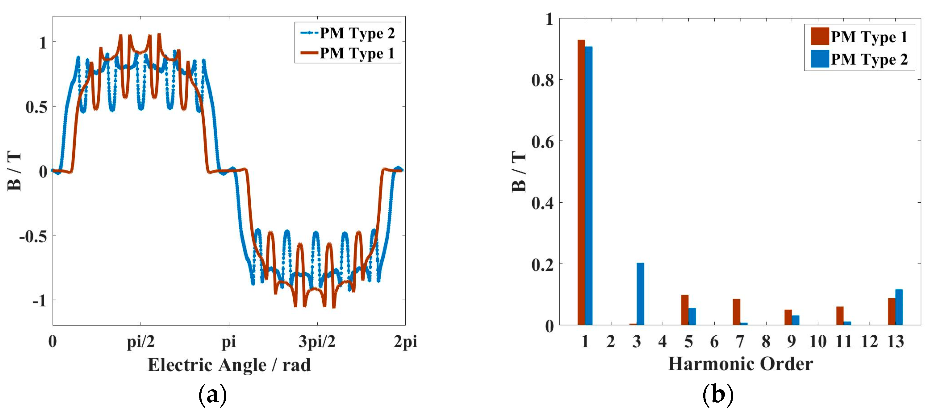
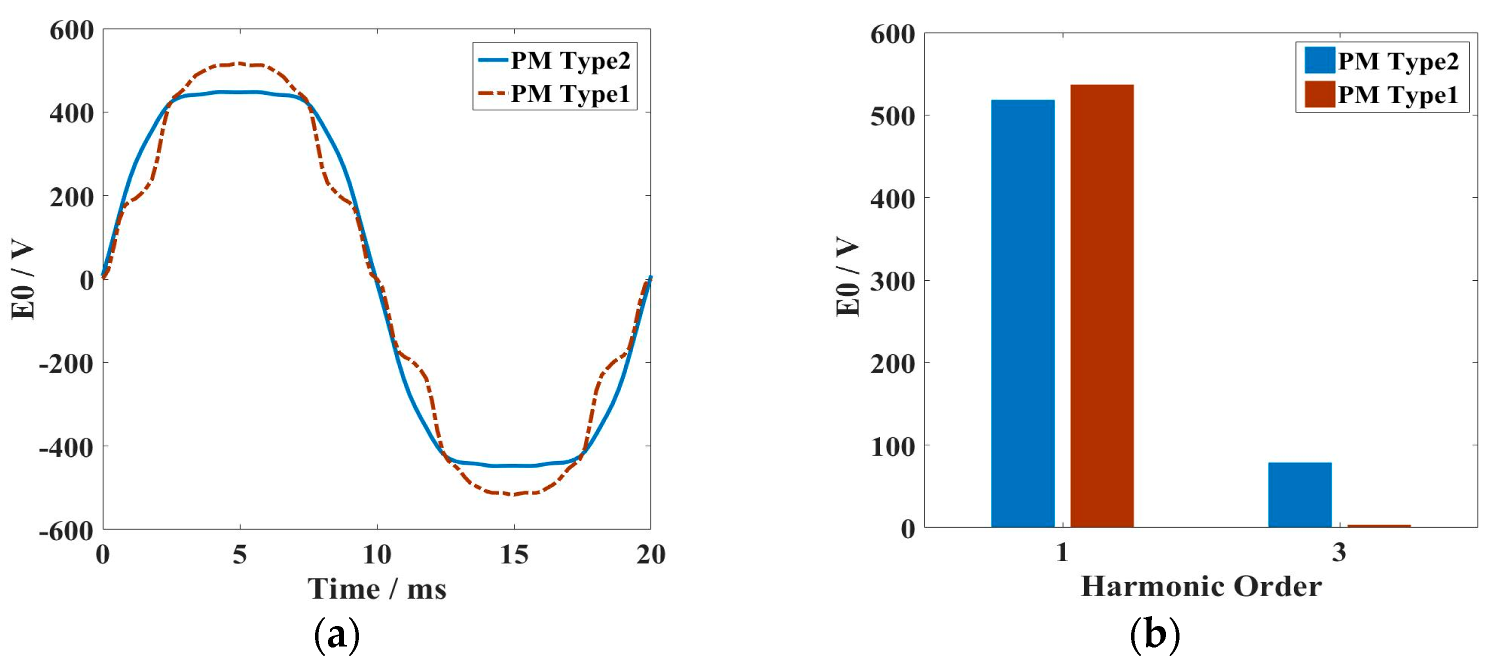
Figure 5 and
Figure 6 compare the waveform of the air-gap magnetic field and the
E0 waveform and Fourier decomposition when two different types of PMs are used.
It can be seen from the figure that when using the sector PM, the 3k-order harmonic in the air-gap magnetic field and the 3k-order harmonic in the E0 are both smaller, which is helpful to reduce the circulating current in the winding and improve the efficiency of the motor. With the same RMS of E0, when the PM is sector-shaped, the effective value of the fundamental component increases from 366.5 V to 379.6 V, and the effective value of the third harmonic decreases from 55.8 V to 2.4 V.
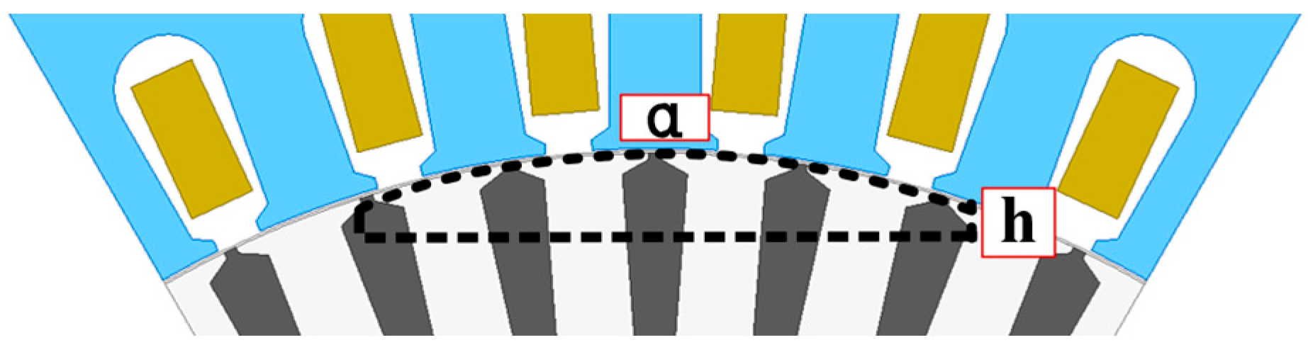
Therefore, the sector-shaped PM is more suitable for the PMR design. For sector PMs, the parameters that can be adjusted include the polar arc factor
α and the thickness
h of the edge of the PM. The parameters of the PM are labeled as shown in
Figure 7.
Obviously, for the same
E0, an infinite number of combinations of
α and
h can be obtained, but the different combinations of the two factors will affect the starting and rated performance of the motor after PMR, which will be analyzed in detail in
Section 3 and
Section 4.
2.3. PMR Design and Motor Performance Analysis
The remanufacturing of IMs must satisfy the original load characteristics and then improve the efficiency and other performance of the motor. The Y2-132M1-6 motor studied in this paper is an IM used in a beam pumping unit. Its load characteristics include a high starting torque, and the motor needs to meet the requirements of full-load starting. After starting, the motor operates under light or medium loads and generally has no overload requirements.
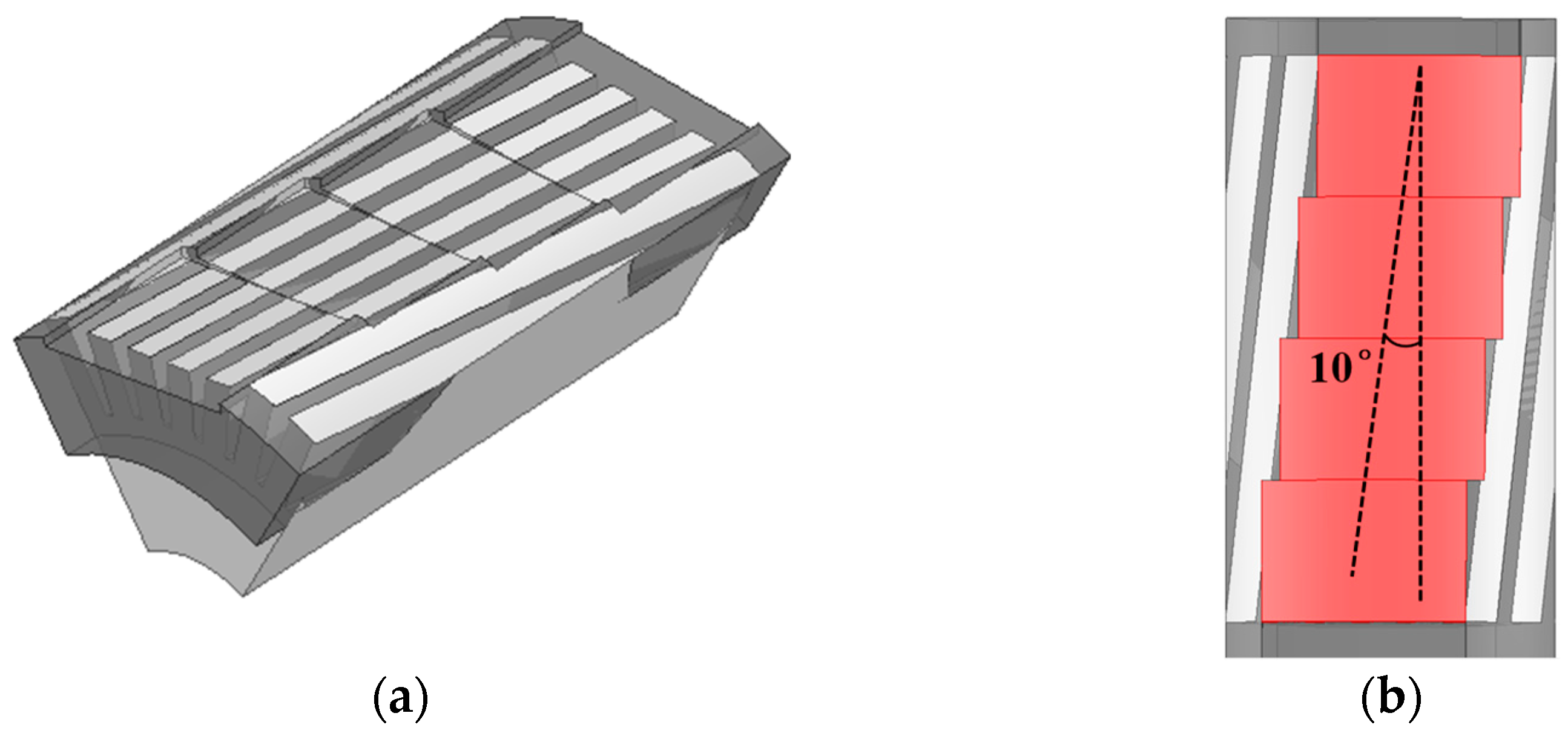
According to the design process described in
Figure 3, the following SELS-PMSM PMR model can be obtained, with detailed dimensions shown in
Table 2. It should be noted that the purpose of using segmented skewed PM poles is to reduce cogging torque and PM losses. However, in order to minimize damage to the starting winding and ensure the symmetry of the modified starting winding, the PMs should be placed symmetrically along the centerline of the starting winding on both sides of the slot as much as possible. The PMR rotor model is shown in
Figure 8.
The performance comparison before and after the PMR is shown in
Table 3. After PMR, the rated efficiency increased from 82% to 89.8%, meeting the IE4 standard. The power factor at the rated point increased from 0.775 to 0.875. From the RMS of line and phase current, it can be seen that the limitation of the improvement of efficiency is due to the copper loss caused by the third harmonic circulating current in the Δ winding.
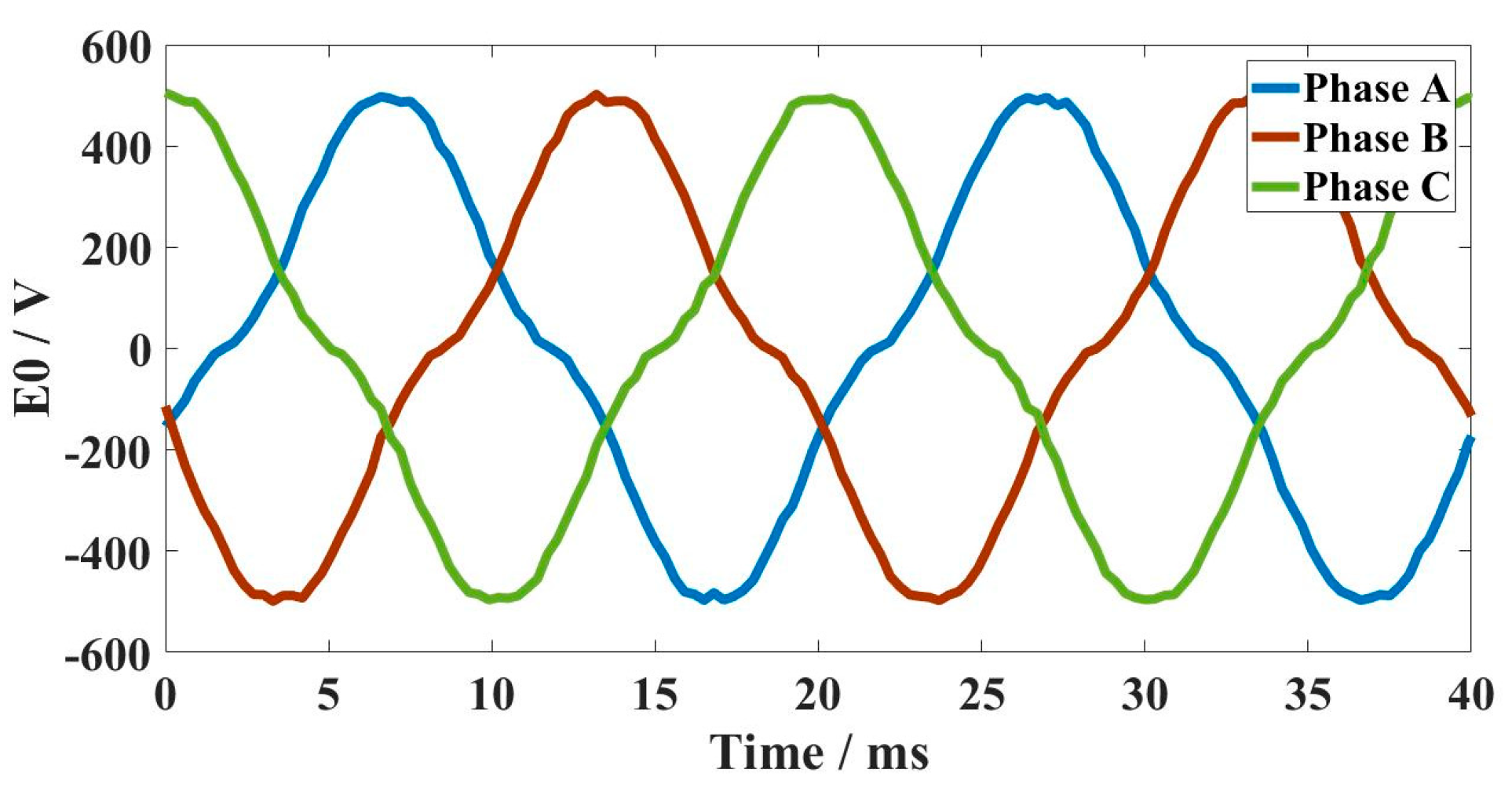
The waveform of the
E0 of the SELS-PMSM is shown in
Figure 9. It can be seen that due to the presence of the third harmonic in the air-gap magnetic field, the
E0 also contains the third harmonic.
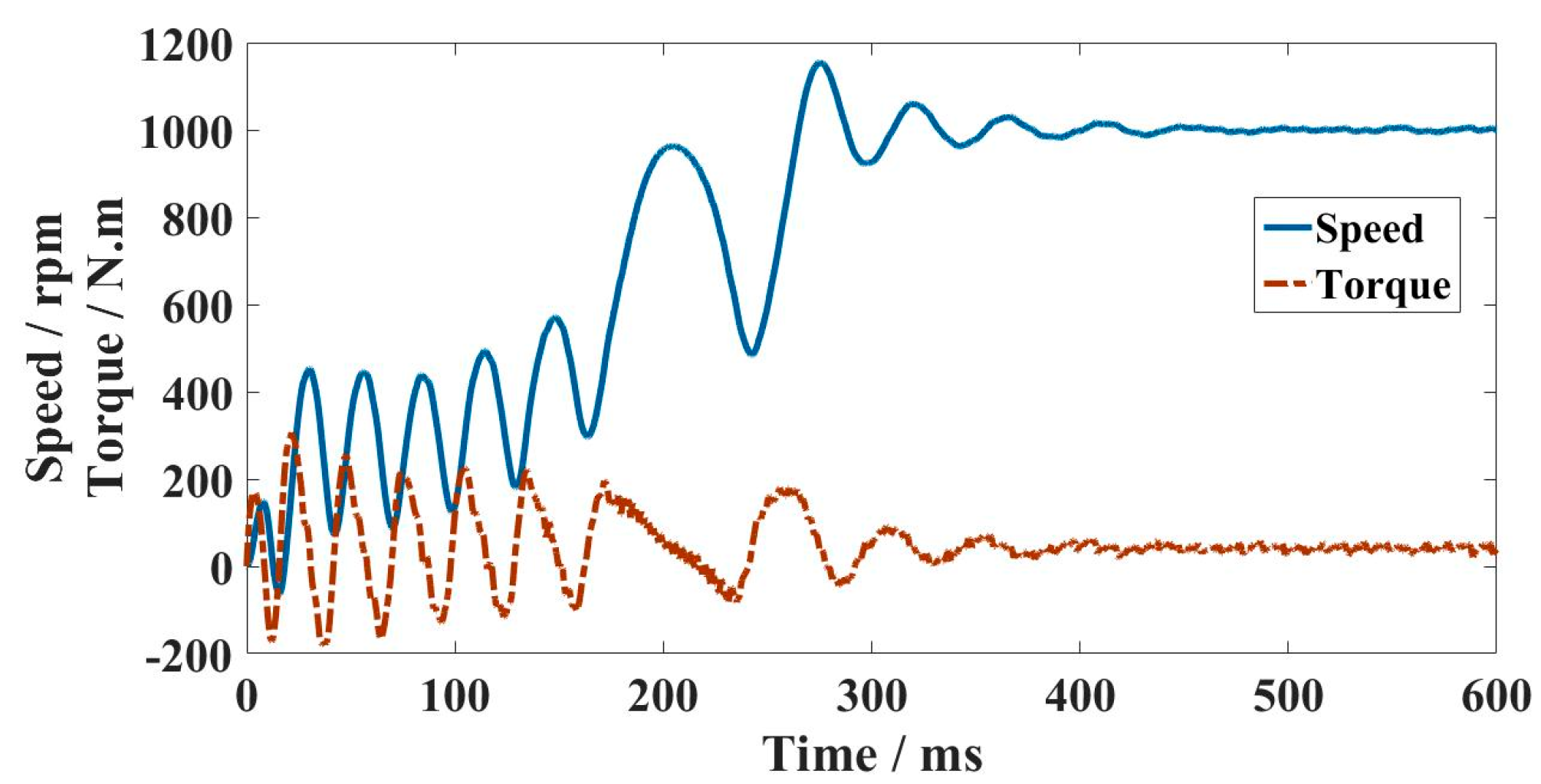
Figure 10 shows the variations of speed and torque of the SELS-PMSM from full-load starting to steady-state operation. As can be seen from the figure, the time of the starting process is about 0.4 s.
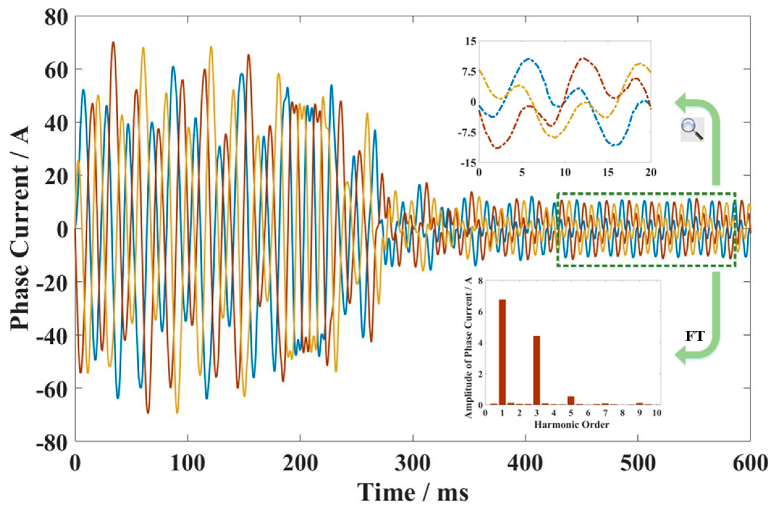
Figure 11 shows the changes in phase current of the SELS-PMSM from start-up to stabilization. By decomposing the steady-state current, the third harmonic can be obtained. Due to the fact that the third harmonic current in each phase winding is in the same time phase and stacked on each other, its amplitude is relatively large.
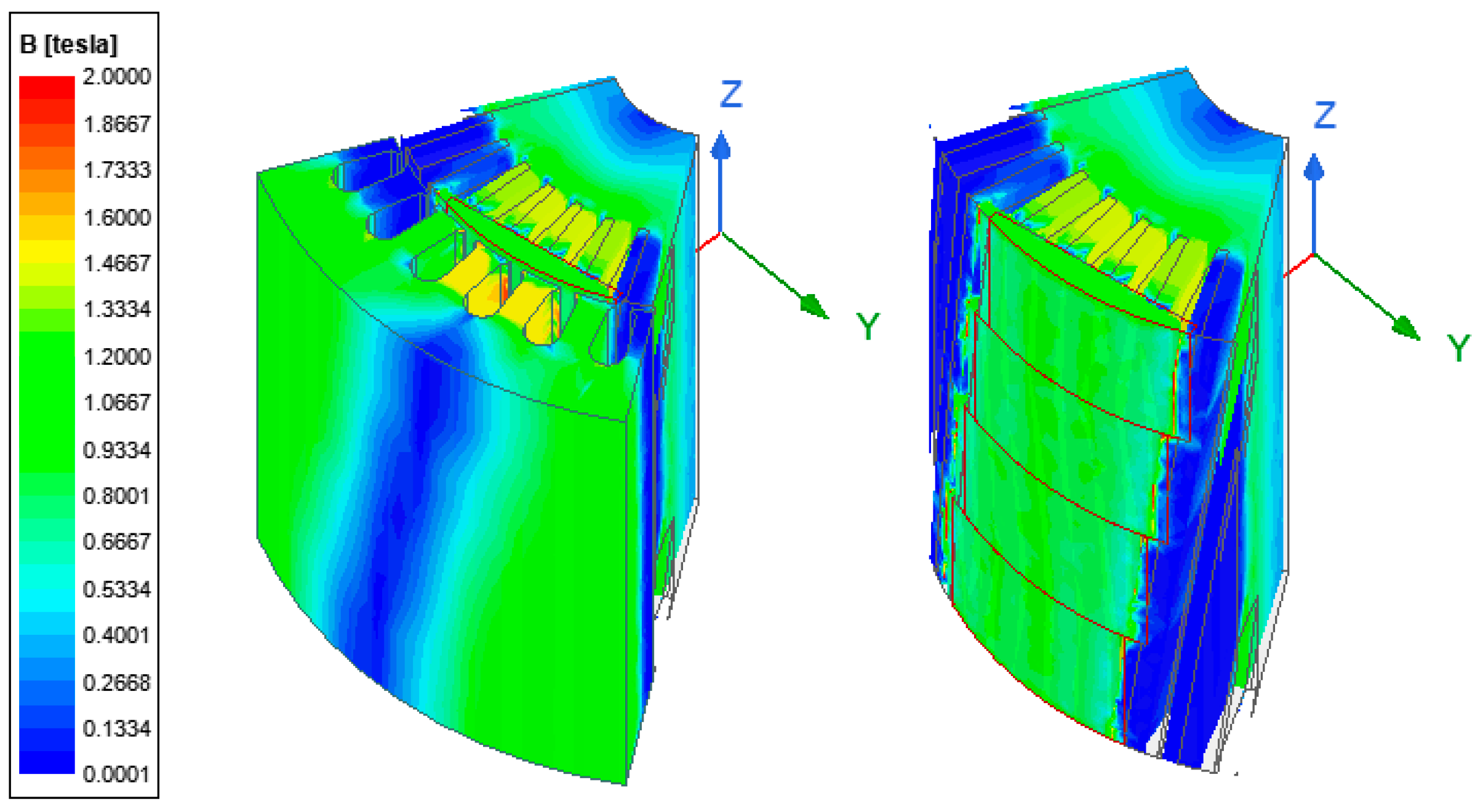
The magnetic density cloud diagram of the motor running at rated load is shown in
Figure 12, and the magnetic density in various parts of the motor is relatively reasonable without the saturation phenomenon.
3. An Analytical Performance Analysis for the Motor Starting Ability after PMR
The introduction of PMs will affect the starting performance of the motor. Due to the general requirement for the self-starting ability of IMs, the motor first needs to realize its original starting capacity after the PMR process.
According to the theory of LSPMSM, the motor includes two types of torque components during the starting process. The average torque
Tav and the pulsating torque
Tcog.
Tav consists of three components, including asynchronous torque
Ta, reluctance torque
Tb, and generative braking torque
Tg. When analyzing starting performance,
Ta and
Tb are often combined as
Tc, as shown in Equation (1).
Tc and
Tg can be calculated by Equations (2) and (3) in the line-start PMSM generally.
In the equation,
r1 represents the resistance of armature windings.
r2′ and
X2′ represent the converted values of rotor resistance and leakage reactance, respectively.
C1 = 1 +
X1/
Xm,
Xm can be approximately calculated by Equation (4).
Xad and
Xaq represent the d-axis and q-axis armature reactance, respectively.
From Equations (3) and (4), it can be seen that the Tc is determined by the magnetic circuit structure and rotor resistance of the stator and rotor and is independent of the E0, while the Tg is jointly affected by the magnetic circuit structure and the E0. Therefore, the following section will further analyze the influence of the factors of the SELS-PMSM on each torque component.
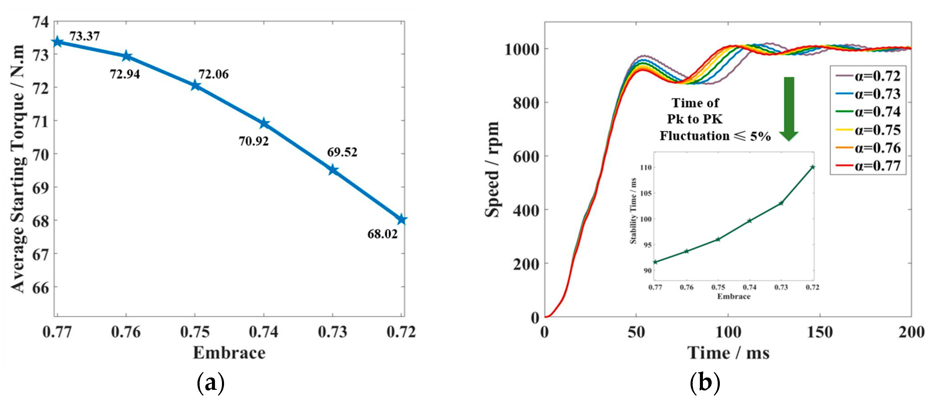
3.1. The Influence of α & h on Starting Performance
From Equation (1), it can be seen that different combinations of the α and h of sector-shaped PMs could generate the same permanent magnetic EMF. But the changes in α and h will change the magnetic circuit structure of the rotor, affect the magnitude of the rotor leakage reactance, and thus change the Tc component in the starting torque.
In order to analyze the impact of different combinations of α and h on Tc and eliminate the interference of E0 on starting torque, it is first assumed that the E0 = U = 380 V at rated speed, and then six different combinations of α and h are given, which are 0.77/1, 0.76/1.25, 0.75/1.55, 0.74/1.85, 0.73/2.25, and 0.72/2.7 (format: α/h, and the unit of h is mm).
Due to the fact that
Tc is only related to the magnetic circuit structure, air is used to replace the PMs in the FE simulation, leaving only the PM slot.
Figure 13a compares the average torque variation of the motor under different combinations of
α and
h. From the figure, it can be seen that as
α decreases and
h increases, the locked torque decreases. During the process of reducing the α from 0.77 to 0.72, the average locked torque decreased by 7.3%.
Figure 13b compares the transient process of no-load starting of the motor under different combinations of
α and
h. It can be seen that as
α decreases, the starting time becomes longer.
According to the simulation, increasing α and decreasing h are beneficial for improving Tc in the starting torque. Therefore, considering the starting ability of the SELS-PMSM and the structural strength of PMs, hmin = 2 mm is selected.
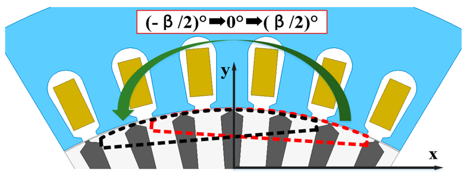
3.2. The Influence of the Slotting Position of PMs on Starting Performance
Due to the fact that the PMR process proposed in this paper will inevitably cause certain damage to the original starting winding, this section will study the impact of the slot position of the rotor on the starting performance.
Set the size
α/h of the PM slot to 0.736/2, and assume that the position angle of the PM slot is 0° when it is symmetrical along the
Y-axis, as shown in
Figure 14. The rotor has a total of 42 starting windings, and the angle
β between each two starting windings is (60/7)°. Considering the symmetry during the position change process, the position angle of the PM slot is decreased from 0° to
β/2. During this process, the changes in the locked torque and starting time of the SELS-PMSM are shown in
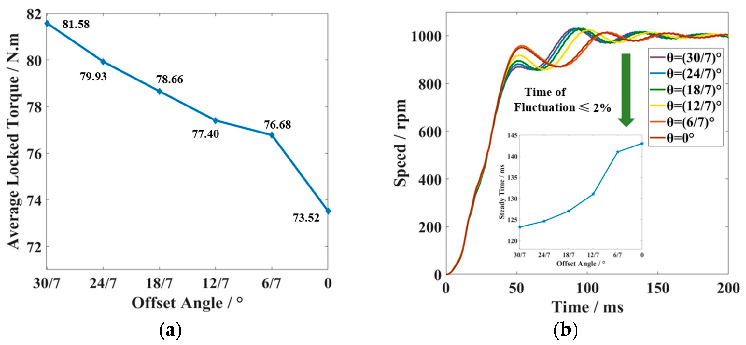
Figure 15.
From the figure, it can be seen that as the rotor position angle increases, the locked torque gradually increases. During the process of increasing the position angle from 0° to
β/2, the average locked torque increased by 10.96%, as shown in
Figure 15a. Correspondingly, the no-load starting time gradually decreases with the increases in position angle, as shown in
Figure 15b. Therefore, a reasonable selection of the slot position of the PM can effectively improve the starting performance of the SELS-PMSM.
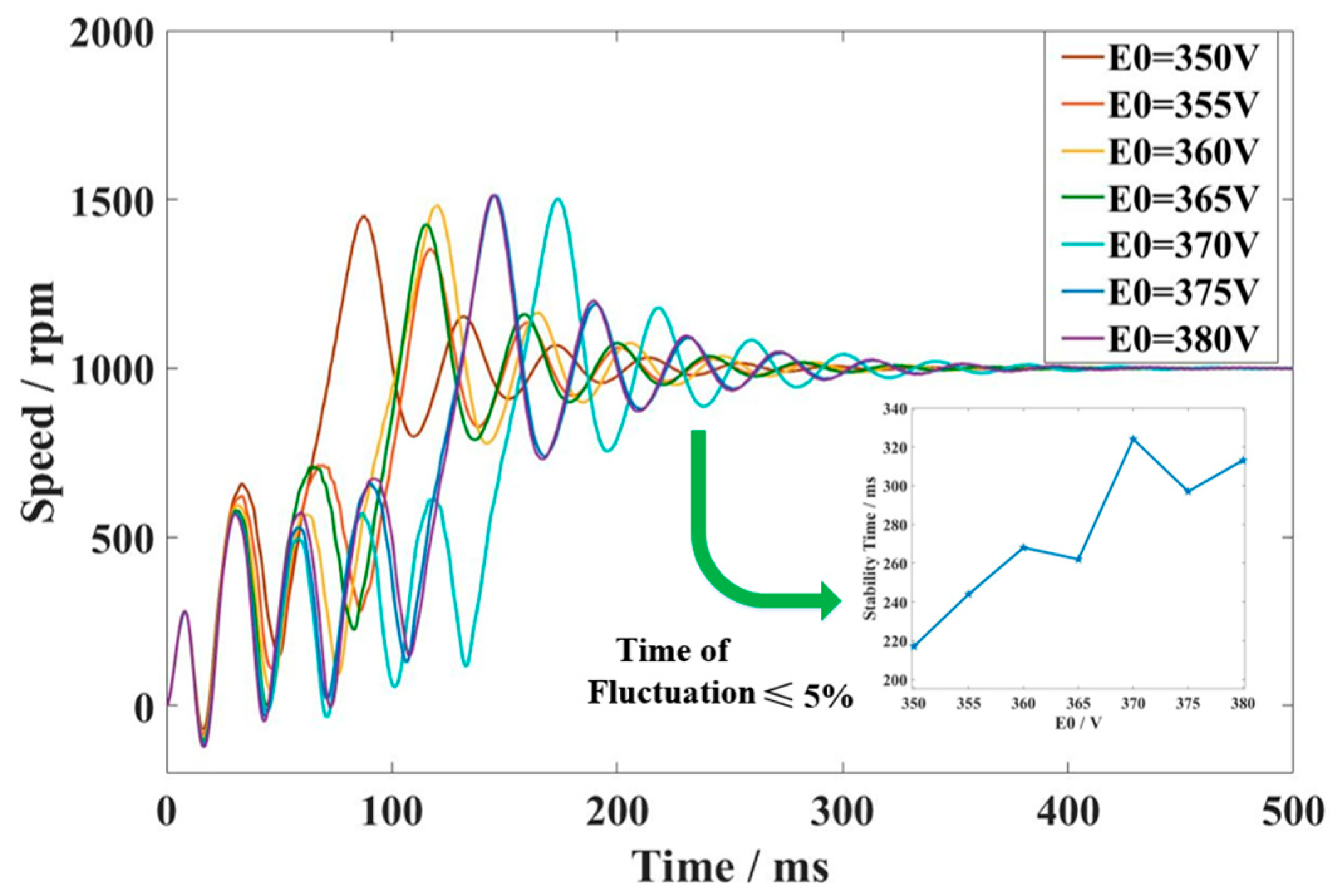
3.3. The Influence of E0 on Starting Performance
As described in Equation (3), E0 will affect the power generation braking torque Tg, changing the starting ability of the motor. Under the premise of determining h, the value of α determines the E0. In order to analyze the impact of E0 on starting ability, seven different combinations of E0 and α are given: 380/0.736, 375/0.726, 370/0.715, 365/0.707, 360/0.697, 355/0.687, and 350/0.676 (format: E0/α, and the unit of E0 is V).
Since the maximum starting torque of the motor is different at different
E0, the starting performance is measured by comparing the no-load starting time for different combinations of
E0 and
α.
Figure 16 compares the no-load starting time
tst_no for different combinations of
E0 and α. It can be seen from the figure that
tst_no increases gradually as
E0 increases.
In summary, the selection of E0 plays a decisive role in the starting ability of the SELS-PMSM, and a too-large E0 may make the motor continuously oscillate during the starting process, making it difficult to start. Reasonable selection of the size α and h of the PM slot and adjustment of the slot position of the PM can also improve the starting ability of the SELS-PMSM.
4. An Analytical Performance Analysis for the Motor Load Ability after PMR
Compared with the original IM, the motor after the PMR process not only has higher efficiency and power factor at the rated point, but also has a wider operation range with higher efficiency and higher power factor. This section will further discuss the factors that affect the load performance of the SELS-PMSM.
4.1. The Influence of E0 on Load Performance
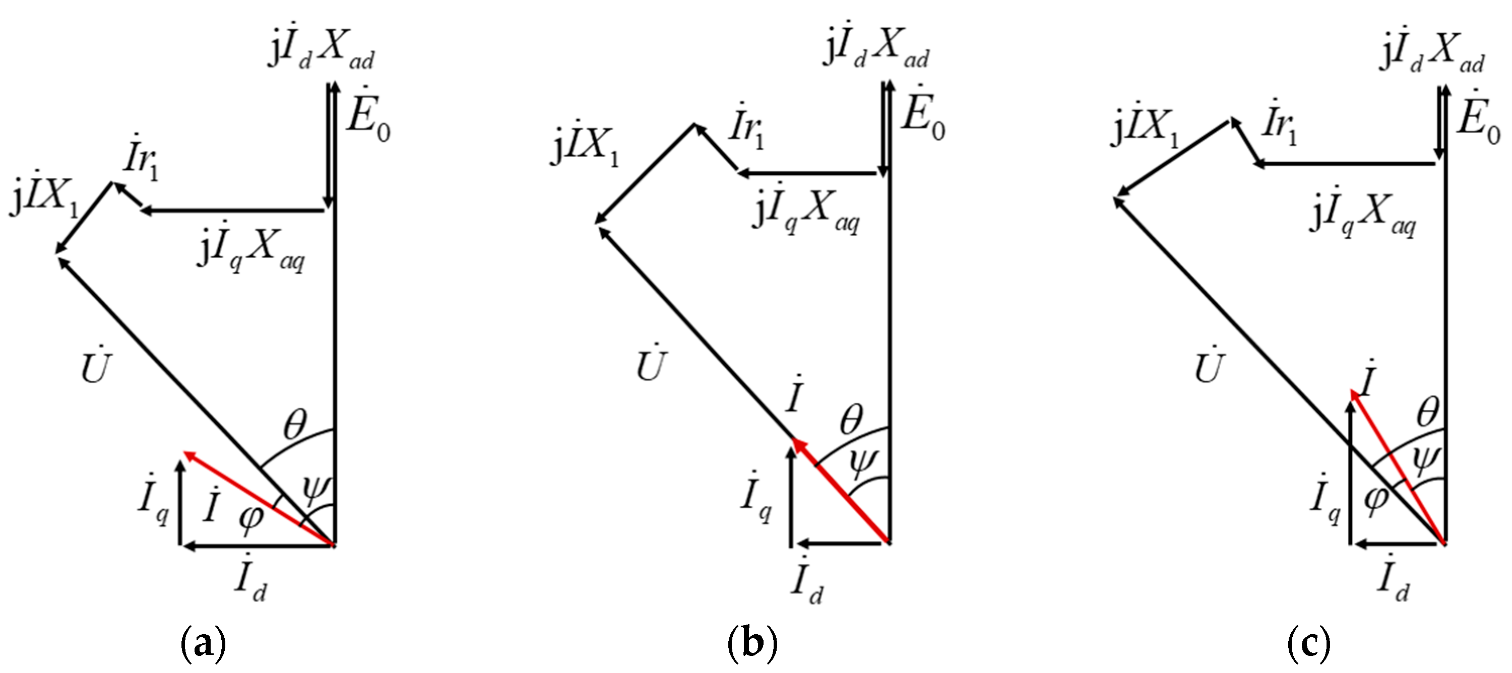
According to the design theory of the PMSM,
E0 is generally designed as a value approximating the supply voltage, making the power factor of the motor close to the unit power factor. At this time, the phase diagram of the PMSM is shown in
Figure 17b. If
E0 is designed too large or too small, the power factor angle of the motor will increase, as shown in
Figure 17a,c.
If the efficiency of the SELS-PMSM needs to be improved, both the invariant and variable losses need to be minimized. For the low-cost PMR method proposed in this paper for IMs, sector-shaped PMs can be used instead of tile-shaped PMs, which in turn reduces the invariant losses by improving the sinusoidal nature of the air-gap magnetic field waveform. Reducing the variable losses can be realized by reducing the stator copper loss. According to the phase diagram, the voltage equation is established in Equation (5).
Solve the armature current according to Equation (5). Derive the current with respect to the
E0 to obtain the condition for the current to be a minimum, as shown in Equation (6).
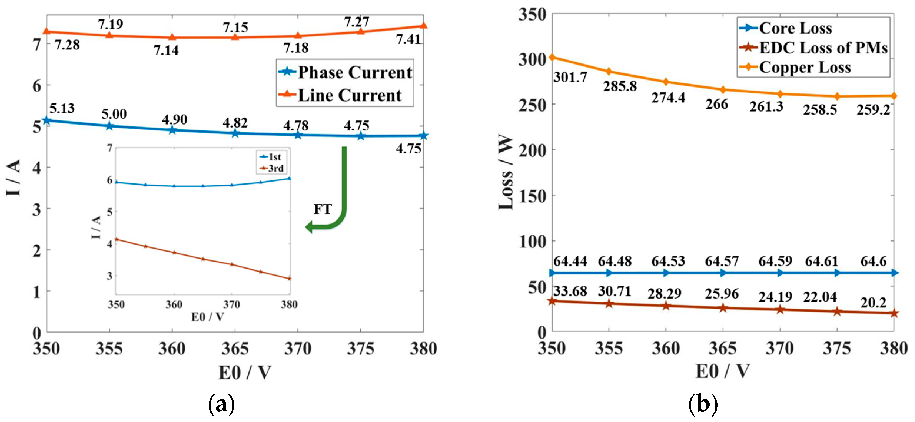
The above equation shows that when E0 is close to U, the stator current is minimized, and the variable losses are minimized. In the practical design of PMSM, the motor tends to have a better performance when E0 is designed to be a slightly smaller value than U. In order to analyze the impact of E0 on rated performance in SELS-PMSM, seven different combinations of E0 and α are given: 380/0.736, 375/0.726, 370/0.715, 365/0.707, 360/0.697, 355/0.687, and 350/0.676 (format: E0/α, and the unit of E0 is V).
The variation of line and phase currents of the SELS-PMSM with
E0/
α combination is shown in
Figure 18a. From the figure, it can be seen that the phase current in the winding continues to decrease with the increase in
E0. By decomposing the phase current, it can be seen that its fundamental component first decreases and then increases, while the third harmonic content continues to decrease. Since the third harmonic circulating current can only circulate in the Δ winding, the line current increases as the fundamental component increases. Therefore, the line current shows a trend of first decreasing and then increasing with the increase in
E0.
The trends of copper loss, core loss, and PM eddy current loss of the SELS-PMSM are shown in
Figure 18b. Due to the decreasing phase current, the copper loss also decreases. The core loss remains basically unchanged as E
0 increases, and the eddy current loss decreases slightly.
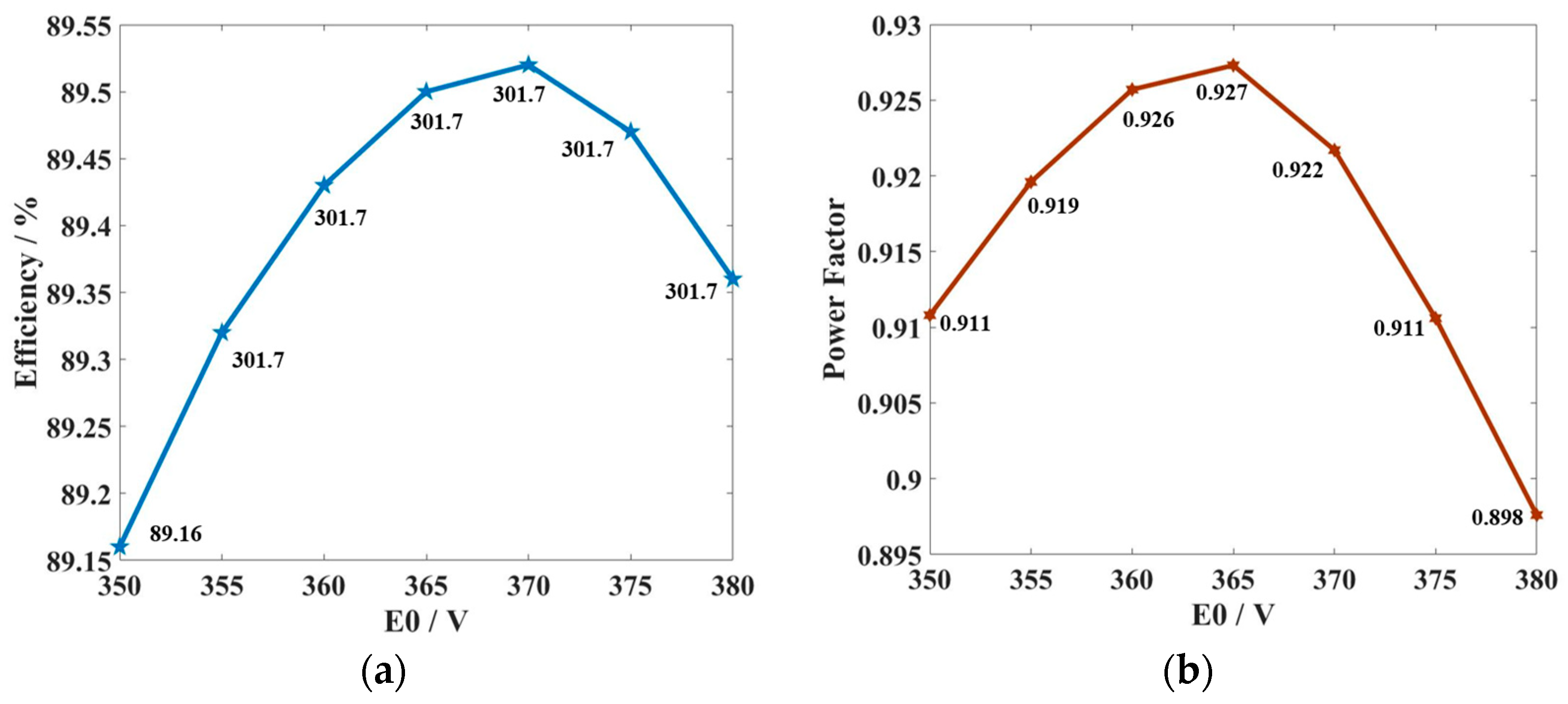
In terms of the efficiency and power factor of the motor, both the efficiency and power factor of the SELS-PMSM increase first and then decrease with the increase in
E0, as shown in
Figure 19. The best performance of the motor is achieved when the value of
E0 is located between 365 V and 370 V.
4.2. The Influence of Winding Connection Method on Load Performance
As can be seen from the previous section, the unavoidable presence of the 3k-order harmonic in the air-gap magnetic field causes the 3k-order harmonic back EMF to be induced in the windings, and when the windings are Δ-connection, the third harmonic currents produce copper loss and heat on the windings.
When the winding is changed from a Δ-connection to a Y-connection, the 3k-order harmonic current cannot circulate, so the efficiency can be improved.
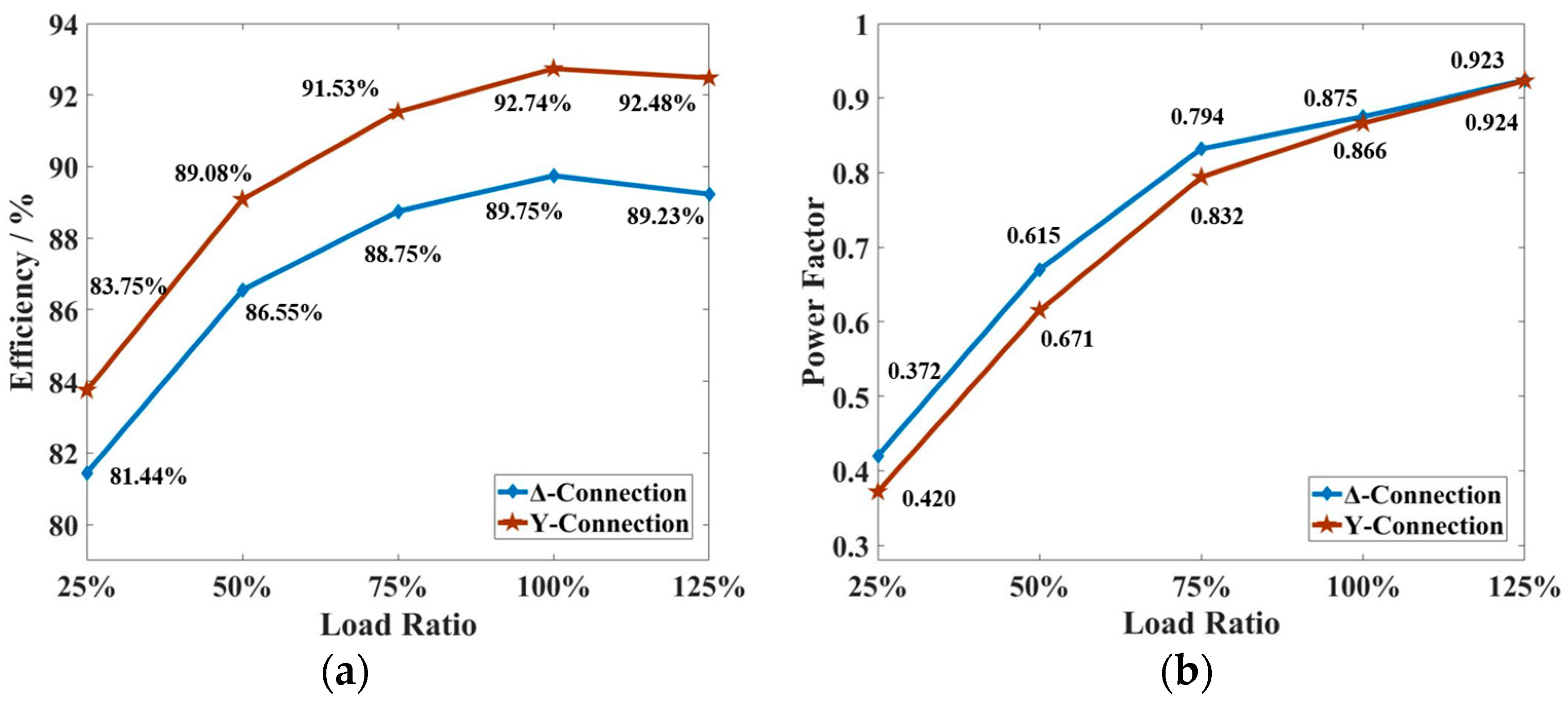
Figure 20 compares the efficiency and power factor of the same SELS-PMSM model under Y-connection (
UN = 660 V) and Δ-connection (
UN = 380 V).
It can be seen that after changing the connection method, the efficiency is improved because the copper loss generated by the 3k-order harmonic current is eliminated, but since the copper loss is also part of the active power, the power factor is basically unchanged under different connection methods.
Compared with SELS-PMSM, IMs have a lower harmonic content of the air-gap magnetic field, so the stator winding connection method does not have much effect on the efficiency of the motor. However, the introduction of PMs will increase the harmonic content of the air-gap magnetic field, so the Y-connected motor can obtain more efficiency improvement after PMR compared to the Δ-connected IM.
4.3. The Influence of Supply Voltage on Load Performance
When the design value of E0 is close to the supply voltage, the motor is able to achieve the best rated performance and a wider economic operating range, but a higher E0 will affect the motor’s starting ability.
The fast and smooth starting of the motor is the basis for steady-state operation, so in some cases where there is the need for a large starting torque, E0 will be designed to a lower value. In order to balance the rated performance of the motor, the SELS-PMSM can be connected to an autotransformer so that it can switch to a lower supply voltage after the starting process is complete.
Taking the PMR design scheme given in
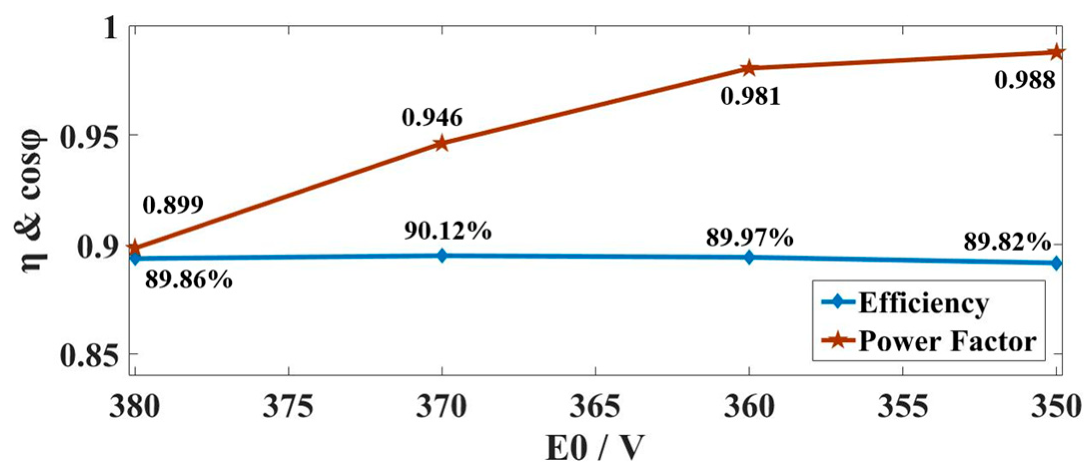
Section 2 as an example, the supply voltage of the windings is decreased linearly from 380 V to 350 V while the motor output maintains the rated torque. During this process, the variations of the efficiency and power factor are shown in
Figure 21. It can be seen that the efficiency remains unchanged during the decrease in the supply voltage, but the power factor can be greatly improved.
Therefore, if the SELS-PMSM needs to meet high starting performance requirements, the value of E0 can be designed smaller, and the motor can be connected to an autotransformer so that the motor can switch the magnitude of the supply voltage after it enters the normal operation state to improve the performance in operation.
5. The Experimental Verification of SELS-PMSM
The Y2-132M1-6 motor is remanufactured according to the design scheme presented in
Section 2. The motor case, stator, windings, and rotor shaft are preserved, the bearings are replaced and the rotor is upgraded.
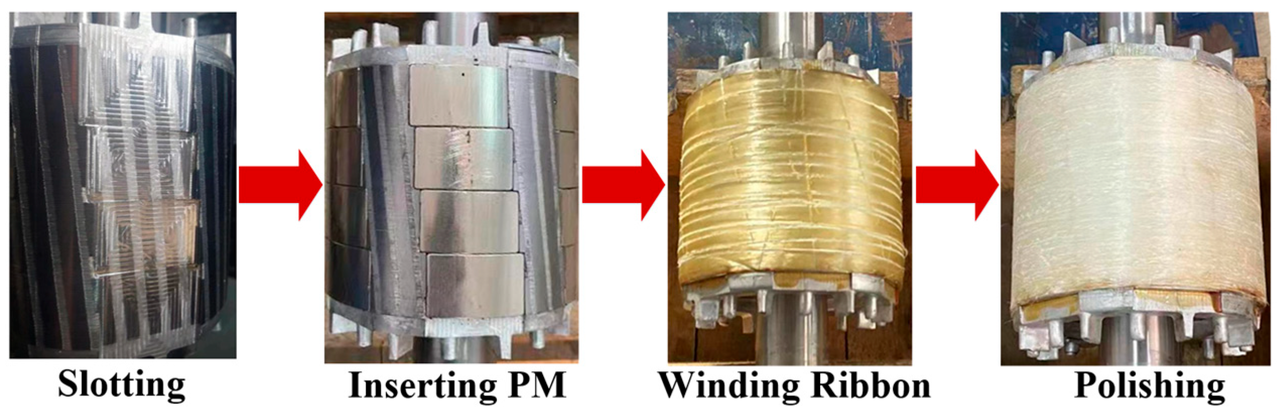
Figure 22 shows in detail the process of the PMR of the motor, which is summarized as follows. Firstly, the surface of the rotor is uniformly turned to a thickness of about 1 mm and then slotted at designated positions on the rotor. Secondly, the PMs should be inserted into the slots, and then a weft-less glass ribbon should be wound around the outer side of the rotor to fix the PMs. Finally, the rotor should be polished to ensure the smoothness and flatness of the rotor surface.
The material costs for the PMR process of the motor are calculated as follows. The materials used in PMR include PMs, weft-less glass ribbons, and bearings. Their costs are RMB 324, RMB 60, and RMB 120 respectively, and the total material cost is RMB 504 (approximately USD 70.1). Due to the regional differences in the cost of labor and equipment used in the PMR process, this paper does not calculate this part of the cost. Currently, the price of the PMSM under the same output power in the Chinese market is about RMB 2000~2500. Obviously, the PMR of the IM has a better economy.
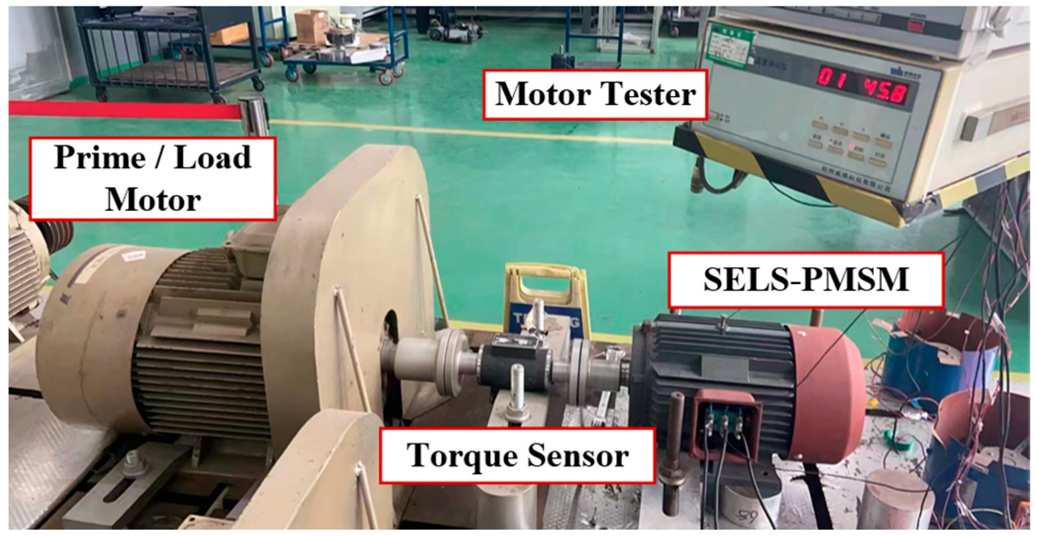
Experiments were conducted on the SELS-PMSM, and an experimental platform was built, as shown in
Figure 23. The SELS-PMSM is connected to a prime/load motor via the torque sensor. When the test motor is not connected to the power supply, the prime motor drags the PMR motor to its rated speed, thus obtaining the waveform of permanent magnet back EMF by oscilloscope. When the test motor is connected to the power supply, the PMR motor drags the load motor, and the load torque of the motor is measured by the torque sensor. Voltage and current waveforms of the motor can be obtained from oscilloscopes and probes connected to the motor, and the output power, efficiency, and power factor of the motor are obtained from the motor tester.
The SELS-PMSM quickly starts when connected to a 380 V AC power supply under the no-load state. However, due to experimental limitations, this paper did not conduct a full-load starting test of the motor under a load torque of 40 N.m.
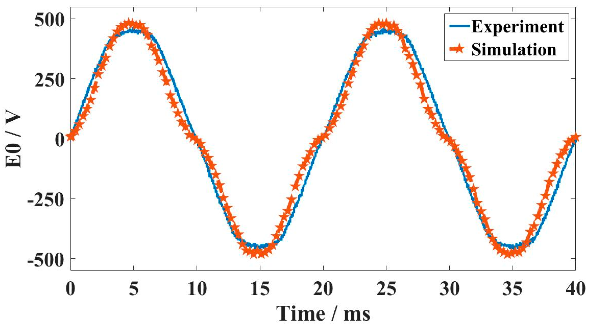
Firstly, a drag experiment was conducted on the SELS-PMSM.
Figure 24 shows the waveform of its permanent magnet back EMF
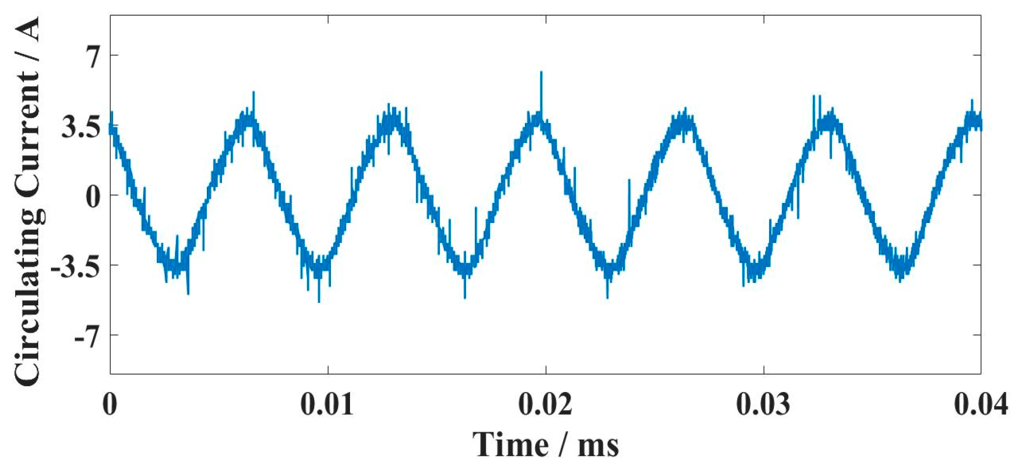
E0. Due to the Δ-connection of the stator winding, the third harmonic back EMF will generate a circulating current in the winding under drag test, and its waveform is measured and shown in
Figure 25.
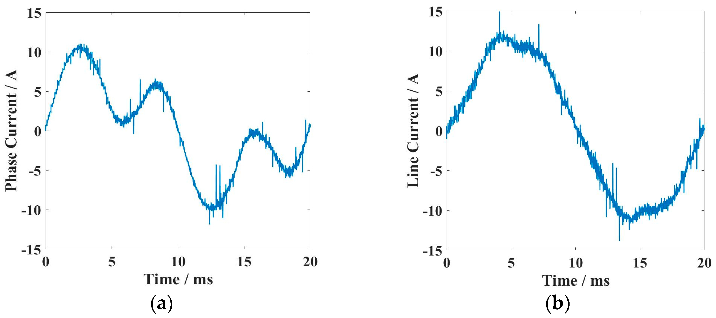
Furthermore, load experiments were conducted on the SELS-PMSM. Rated load was applied to the motor, and the line/phase current waveform was obtained through an oscilloscope, as shown in
Figure 26.
According to the measured data, the effective value of the line/phase current of the SELS-PMSM under rated load is 8.26/5.5 A. The third harmonic current is the reason for the large phase current. From
Figure 26, it can also be seen that the FE simulation and experiments are consistent.
Table 4 further compares the temperature rise of the motor before and after the PMR process. The temperature rise data reflects the steady-state value of the stator winding of the tested motor running continuously for 1 h under rated load. Although the third harmonic current in the winding enlarges the copper loss of the stator, the temperature rise of the SELS-PMSM under continuous load is lower than that of the original IM due to the heating reduction of the rotor.
The load ratio was changed, and the efficiency and power factor of the SELS-PMSM were measured during the process of linearly increasing the load from 25% (9.55 N·m) to 125% (47.75 N·m). The results are shown in
Figure 27. From the experimental data at the rated point, the efficiency of the motor after PMR is increased from 82% to 88.45%, and the power factor is increased from 0.775 to 0.847.
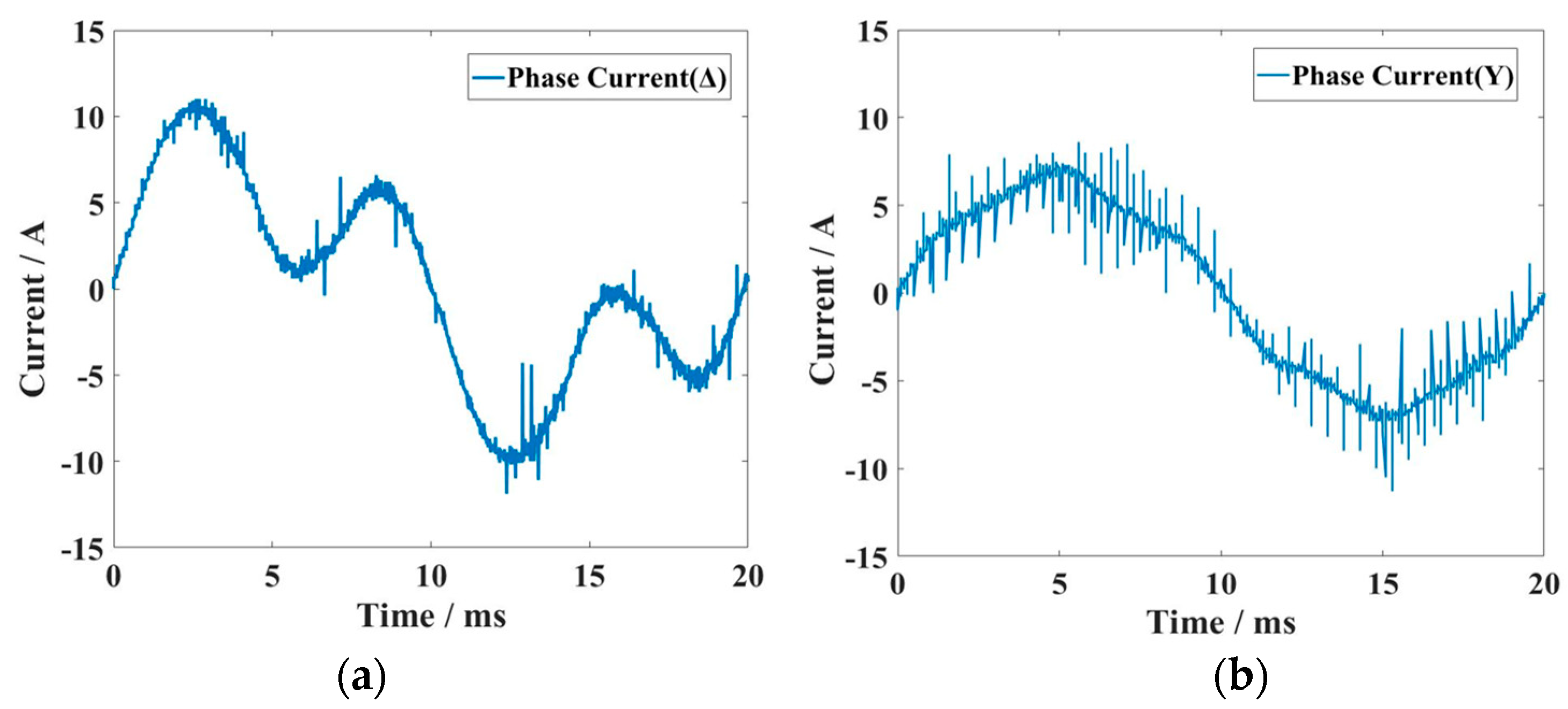
Further, the experiments about changing the winding connections are as follows. After changing the connection from Δ to Y, the rated voltage of the motor increased from 380 V to 660 V, but the rated power of the motor remained unchanged.
Figure 28 compares the phase current before and after changing the connection method. It can be seen that due to the elimination of the third harmonic, the sinusoidal nature of the current waveform is significantly improved.
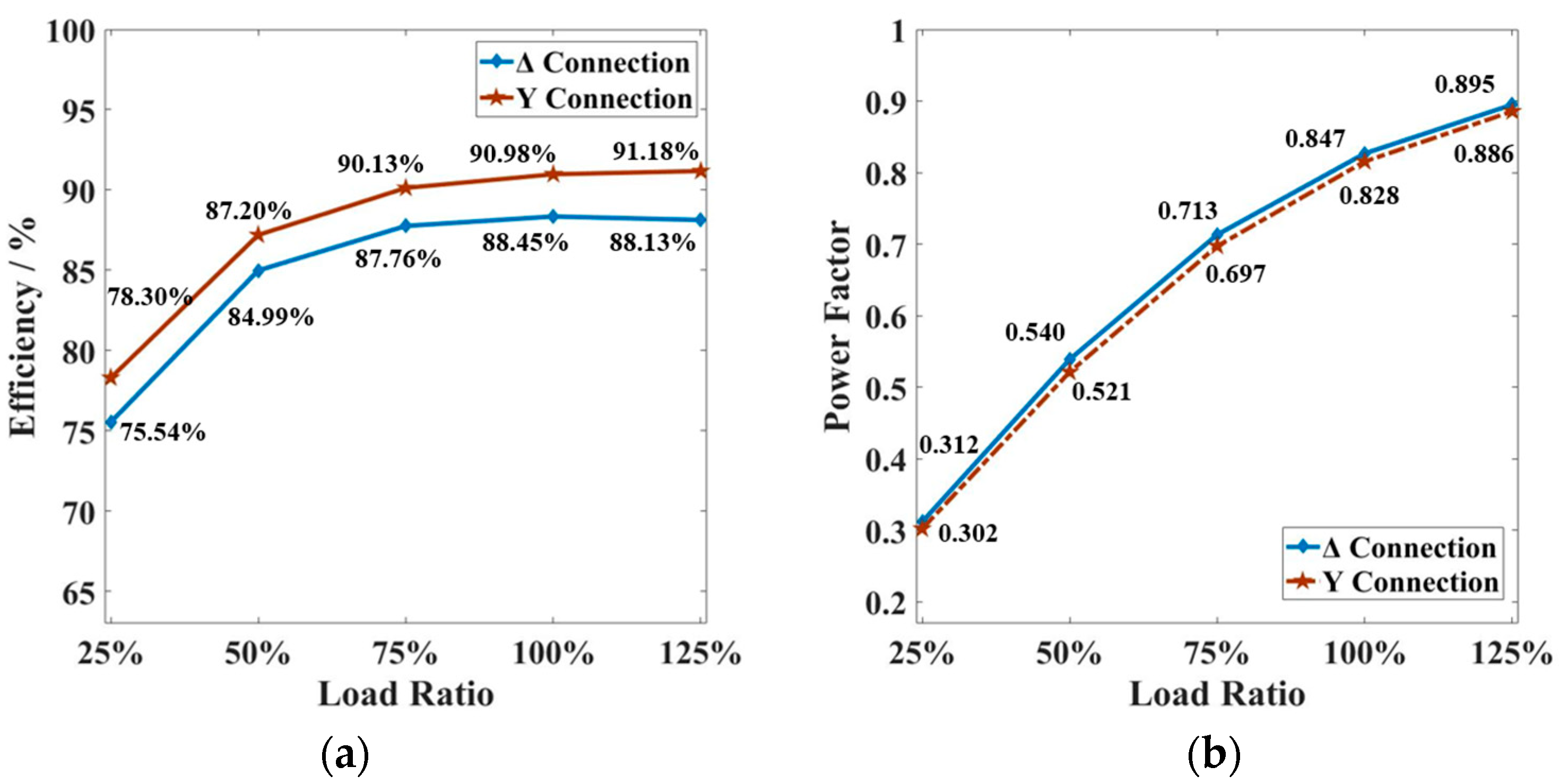
Through experiments, compare the efficiency and power factor before and after changing the connection method under different load rates, as shown in
Figure 29. The experiment results are consistent with the simulation results. Due to the elimination of the third harmonic, the copper loss decreases, resulting in an improvement in efficiency. When using Y-connection, the efficiency of the SELS-PMSM at the rated point is up to 90.98%. However, changing the winding connection method has little effect on the power factor. The power factor of the SELS-PMSM is not improved under the Y-connection.
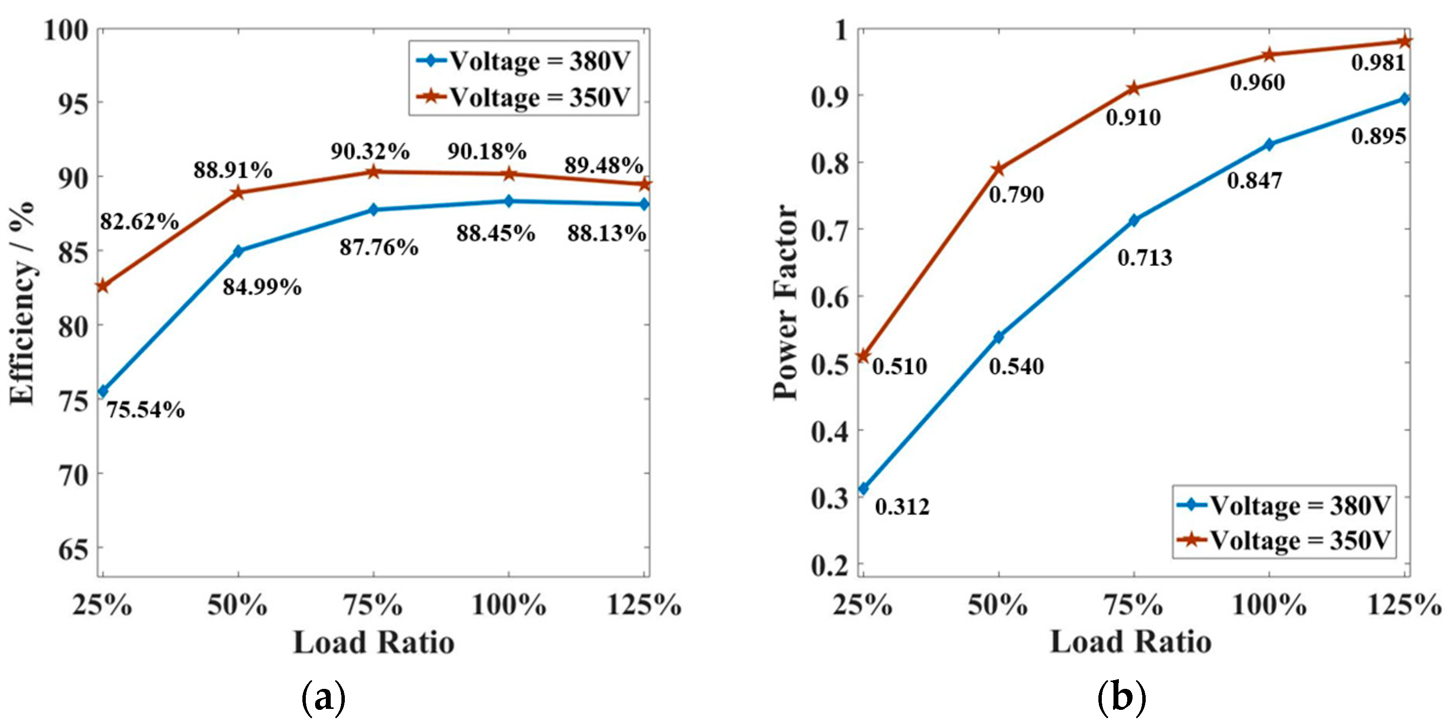
Figure 30 further compares the effect of reducing the supply voltage through experiments. When the supply voltage of the SELS-PMSM decreases from 380 V to 355 V, the variation of efficiency and power factor under different load ratios is shown in
Figure 30.
It can be seen that reducing the supply voltage can improve the efficiency and power factor of the SELS-PMSM over a wide load range. Therefore, for engineering applications such as pumping units that require high starting torque and low steady-state operating load rates, SELS-PMSM can be connected to an autotransformer. The motor starts at rated voltage and then switches the voltage after completing the start, allowing the motor to operate under a reduced voltage to further improve the overall energy efficiency performance of the motor.
Furthermore,
Table 5 compares the performance improvement and remanufacturing cost of the induction motor by the PMR method proposed in this paper with the existing remanufacturing practices in the literature [
7,
8,
9,
10,
21].
In the above literature, except for Reference [
7] which gives the material cost of the motor directly, the rest of the papers are not calculated for the remanufacturing cost of each motor. So, in this paper, the material cost is estimated based on the dimensional data of the rotor, permanent magnets, and rotor shaft provided in [
8,
9,
10,
21]. The estimated material costs are further compared in
Table 6. In the table, References [
8,
9,
10] are all about transforming IMs into PMSMs, so the materials include Si-steel sheets, PMs, bearings, and rotor shafts. Reference [
21] remanufactures the IM into a reluctance motor and hence the materials include Si-steel sheets, bearings, and rotor shaft. The PMR method proposed in this paper preserves the original induction rotor. Therefore, the materials include PMs, bearings, and weft-less glass ribbons. Moreover, in order to accurately compare the remanufacturing cost of the motor, the cost per unit of output power is further calculated in the table.
Finally, it can be seen from
Table 5 that the remanufacturing methods proposed in [
7,
21] provide a small efficiency improvement of the motor. Reference [
7] replaced the rotor of aluminum bars by using Al-Cu composite bars, and the efficiency was only improved from 92.91% to 93.5%. Reference [
21] replaced the induction rotor with a synchronous reluctance rotor, and the efficiency before and after the replacement was 86.7% and 87.3%, respectively. Both of these two remanufacturing methods have a lower cost per unit of power due to the non-use of PMs, but the remanufacturing effects are also limited. References [
8,
9,
10] transformed the IMs into PMSMs, and the efficiency improvement of the motors is more obvious. By comparing the PMR methods proposed in this paper with those in [
8,
9,
10], it can be seen that the PMR method has the lowest remanufacturing cost per unit of power under the premise of approximate efficiency improvement. Its cost is only 51.6% of the cost per unit of power in [
9]. Obviously, the PMR method proposed in this paper has a significant advantage based on the small differences in efficiency improvement.
The conclusions of the experiments of the SELS-PMSM are as follows:
- (a)
By conducting drag and load experiments on the motor, it can be seen that the simulation is consistent with the experiment.
- (b)
By directly transforming the induction rotor into a PM rotor, the motor performance has been significantly improved. The rated efficiency of the motor increased from 82% to 88.45%, and the power factor increased from 0.775 to 0.847
- (c)
Changing the winding connection form from Δ to Y can eliminate the third harmonic circulating current in the stator and further improve the motor efficiency to 90.98%.
- (d)
For some engineering applications, SELS-PMSM can be started at rated voltage and operated at a reduced voltage after starting, thereby improving efficiency and power factor during steady-state operation.
- (e)
By comparing with the existing studies, it can be seen that the remanufacturing cost of the proposed method in this paper is significantly lower than that of the existing remanufacturing cost for induction motors.
- (f)
The SELS-PMSM starts smoothly and rapidly when it is not loaded, but due to experimental conditions, the full-load starting ability of the motor is not tested.
6. Conclusions
This paper proposes a low-cost PMR method for IMs, which completely preserves the original IM’s case, stator core, and windings and upgrades the induction rotor into a PM Rotor by directly turning, milling slots, and embedding PMs in the squirrel-cage rotor of the original IM motor. In order to achieve a good design for remanufacturing, this paper proposes a general design process for the PMR of induction motors. Based on this process, a Y2-132M1-6 induction motor is designed. The FE simulation results show that the PMR of the IM can improve the rated point efficiency of the original induction motor from 82% to 89.8% and the power factor from 0.775 to 0.875.
This paper further analyzes the factors affecting the starting performance of remanufactured motors, including the α/h combination of the PM, the slotting position of the PM, and the selection of the E0. From the simulation and analysis results, the selection of E0 has a decisive influence on the starting performance of the motor, while the reasonable selection of the α/h combination and the slotting position of the PM can also improve the starting performance of the remanufactured motor.
This paper also analyzes the factors affecting the rated performance of remanufactured motors, including the selection of E0, the different connections of the windings, and the effect of the motor supply voltage. From the simulation results, when E0 is close to and slightly less than the external voltage, the motor has the best rated point performance. When the stator winding is Y-connected, the performance of the PMR motor has better performance improvement. Meanwhile, for the occasions where the starting performance is required to be high, this paper also proposes the idea of full voltage starting and then working under a reduced voltage, so as to improve the performance of the motor at the rated point.
Finally, a Y2-132M1-6 PMR prototype motor is made, and relevant experiments are carried out. The experimental results show that the efficiency of the motor at the rated point is improved by about 7%, which is basically consistent with the simulation results. At the same time, this paper also calculates the material cost of the PMR process. From the point of view of material cost in the PMR process, the cost is only 20~25% of replacing PMSM with the same output power and significantly lower than the remanufacturing methods in existing studies.


