Review

Energy Performance and Thermal Comfort Delivery Capabilities of Solid-Desiccant Rotor-Based Air-Conditioning for Warm to Hot and Humid Climates—A Critical Review

1
Faculty of Science and Technology, Charles Darwin University, Ellengowan Dr, Casuarina, NT 0810, Australia
2
Future Industries Institute, University of South Australia, Mawson Lakes Campus, Mawson Lakes, SA 5095, Australia
*
Author to whom correspondence should be addressed.
Energies 2023, 16(16), 6032; https://doi.org/10.3390/en16166032
Submission received: 21 June 2023 / Revised: 3 August 2023 / Accepted: 7 August 2023 / Published: 17 August 2023
(This article belongs to the Topic Built Environment and Human Comfort)

Abstract

:
There has been considerable research worldwide on desiccant-based air-conditioning during the past 30 years. The rationale for the push for this new research focus has been twofold: (a) the need to provide an alternative to conventional refrigerative air-conditioning systems which rely heavily on fossil fuels as their energy sources, and (b) the need to provide better thermal comfort in air-conditioned spaces in warm to hot and humid climates. A desiccant air-conditioning system consists of several components to cool and dehumidify the air before it is supplied to a conditioned space. Earlier research work has identified the potential advantages of this technology, which include the following: (1) working fluids that do not impact on the ozone layer, (2) reduced electricity consumption, (3) improved indoor air quality, (4) simpler construction and less maintenance, and (5) integral provision of heating and cooling for cold/temperate climates. On the other hand, the authors of this paper identified the following drawbacks: (1) inevitable heating of air while being dehumidified, (2) the need for desiccant regeneration and low thermal COP paradox, (3) limited options for regeneration heat sources, (4) limited options for reliable cooling, and (5) low electrical coefficient of performance (COP). This paper presents a critical review of the energy and thermal comfort performance of solid-desiccant rotor-based air-conditioning systems, and discusses in detail their potential advantages and drawbacks. This critical review found that the drawbacks of the systems outweigh their identified advantages. The main reason for this is the inevitable heating of air while being dehumidified and counterintuitive addition of moisture to air during the evaporative cooling process. During the past 30 years of research and development efforts, no significant innovations have been discovered to resolve these crucial issues. Unless future research and development is directed to find a breakthrough, this technology will have limited commercial application.

1. Introduction

Thermal comfort requirements of occupants in built environments require a significant energy demand in the building sector worldwide [1,2]. In hot and humid climates, the energy demand due to air-conditioning consists of satisfying both sensible and latent loads of buildings. To date, air-conditioning systems in hot and humid climates are mainly served by conventional refrigerative systems which rely mainly on fossil fuel. However, these systems often operate inefficiently or deliver poor thermal comfort in certain circumstances. At part-load conditions, when the system capacity is reduced to respond to low sensible cooling demand, the humidity level in the conditioned space may rise due to reduced dehumidification capacity of the system. Or alternatively, in order to maintain the acceptable space humidity level, overcooling and reheating are inevitable, which increases the system energy consumption.
In serving the load, conventional vapor compression refrigeration systems generally operate either as a direct expansion (DX) or as a ducted system. In DX systems, the cooling and dehumidifying component—called the evaporator—is located in the conditioned space, normally on the wall or attached to the ceiling. The latter is normally the case for the DX ducted system. The DX system is gaining popularity for its avoidance of ducting and associated piping work in general, which leads to reduced installation cost. While the thermal comfort conditions can easily be maintained using a DX system, it suffers from a major drawback, that is, its lack of fresh air to the conditioned space. This is especially concerning in public buildings such as schools, theaters, and lecture halls, which require sufficient fresh air. In such a situation, a separate ventilation unit needs to be installed.
The refrigerative ducted cooling system operates either as a constant air volume (CAV) system or a variable air volume (VAV) system. In a CAV system, the air flow rate to the conditioned space is set constant, but the air supply temperature is varied according to the thermal demand. In a VAV system, on the other hand, the air supply volume flow rate is varied according to the load while the supply air temperature is set constant. Both systems have drawbacks. The operation of a CAV system during part load means the control system reduces the refrigerant flow rate which in turn reduces the system dehumidifying capability. This can result in unacceptable space humidity levels through the “moisture staircase” phenomenon [3,4,5]. To avoid this, the system is operated to serve the design load; furthermore, to avoid space overcooling in commercial installations, reheating of air is inevitable.
The emergence of the VAV system was meant to overcome an inherent inefficient operation of CAV systems. In the VAV system, the air supply flow rate to the conditioned space is varied according to the prevailing cooling demand. During part-load operation, the system reduces the air flow rate, resulting in reduced fan power demand which in turn reduces electrical energy consumption. The drawback of this method is that the fresh air delivered to the room can reach a situation where the minimum fresh air requirement set by the applicable standard is not satisfied, resulting in stuffy conditioned spaces. This issue is similar to that encountered by the DX system, where the evaporator is installed within the conditioned space mentioned above. Thus, while lower energy consumption is achieved, the thermal comfort and room air quality is largely compromised.
In the refrigerative vapor-compression air-conditioning system, electrical energy is required to drive the compressor to recirculate the refrigerant within the vapor-compression-cycle system. In addition, electrical energy is also required to distribute or blow the cooled and dehumidified air either directly into the DX system or through the cooling coil. Electrical energy is also required to cool the refrigerant as it passes through the condensing unit. This can be accomplished through either a water cooled or an air-cooled system [6].
Given the above issues, over the past three decades, there has been considerable research in identifying better substitutes for refrigerative systems. In short, the research community has been looking for or developing systems that reduce reliance on fossil fuel use in air-conditioning but at the same time deliver comparable or even better thermal comfort conditions for space occupants. Thermally driven air-conditioning is one of the alternative technologies that has been investigated. In these systems, thermal energy is used—instead of an electrically powered compressor—to cool and dehumidify air.
This paper focusses on solid-desiccant-based air-conditioning systems in an open cycle, i.e., direct treatment of fresh air through solid sorbent in a dehumidifying rotor and other components such as the evaporative cooler, which requires regeneration of the solid sorbent [7]. Other thermally driven systems and their classification can be found in [7]. Many studies have claimed that these systems use much less electrical energy and therefore their electrical coefficient of performance (COP)—defined as the ratio of cooling effect and the electrical energy used—is generally much higher than the electrical COP of conventional refrigerative air-conditioning systems. Such systems can be powered by any thermal energy source such as industrial waste heat and solar energy. However, the latter has been the main focus of the research lately because the solar thermal production time matches the time of building cooling demand for commercial buildings.
This paper provides a critical overview of the solid-desiccant-based air-conditioning systems that have been the object of research and that have been published in the various scientific literature. Specifically, this review paper focuses on systems that have the desiccant dehumidification wheel/rotor as their main core component. Do the basic principles of these systems conform to the goal of achieving thermal comfort in air-conditioned spaces? Are the general claims of high electrical COP justifiable? Do these systems have the potential to resolve the humidity issues in the tropics for which they are intended to operate? These and other issues related to these systems are critically looked at in this paper. The authors feel the need for such a critical overview in the midst of vastly growing research interest in this field. Existing review papers which are normally the steppingstones for researchers keen on this research topic generally overlook or avoid asking those critical questions. Instead, they merely present various research activities and technology development without looking critically at the unique outcomes of each research study or how these, if any, have resolved existing research issues. In short, this critical overview is needed to determine whether this research topic is worth pursuing as it could potentially lead to impractical implementation, and to avoid unnecessary research duplication that potentially leads to research resources (time, funding, and expertise) being spent unwisely.
This paper proceeds by presenting an overview of the thermal comfort requirements in the built environment. This is followed by an overview of the various configurations of these systems that have been proposed, researched, and trialed. The section that follows discusses the strength and drawbacks of these systems and their ramifications. Finally, lessons learned from various research works provide the basis for Section 5, dedicated to future research directions.

2. Revisiting the Goal of Air-Conditioning Installation in the Built Environment

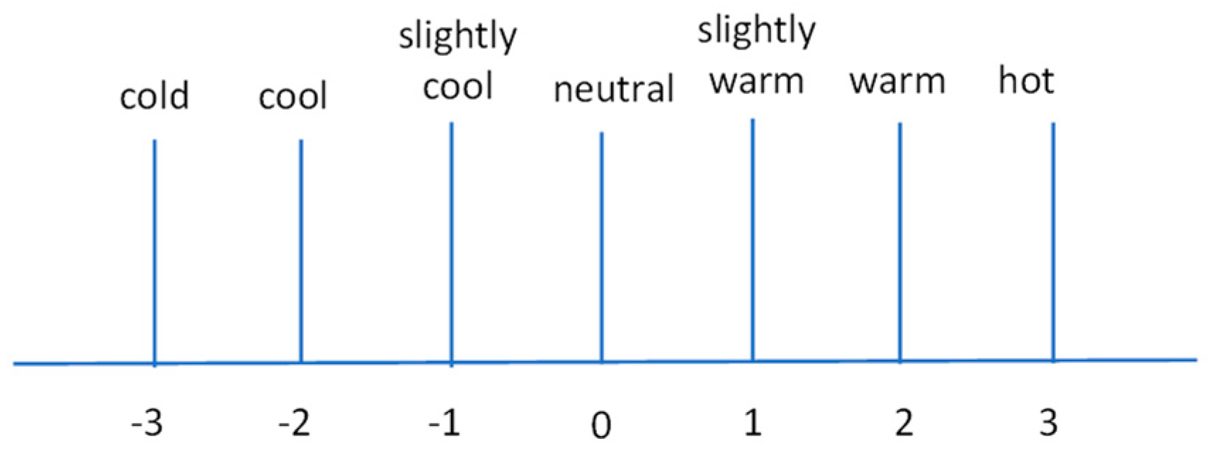
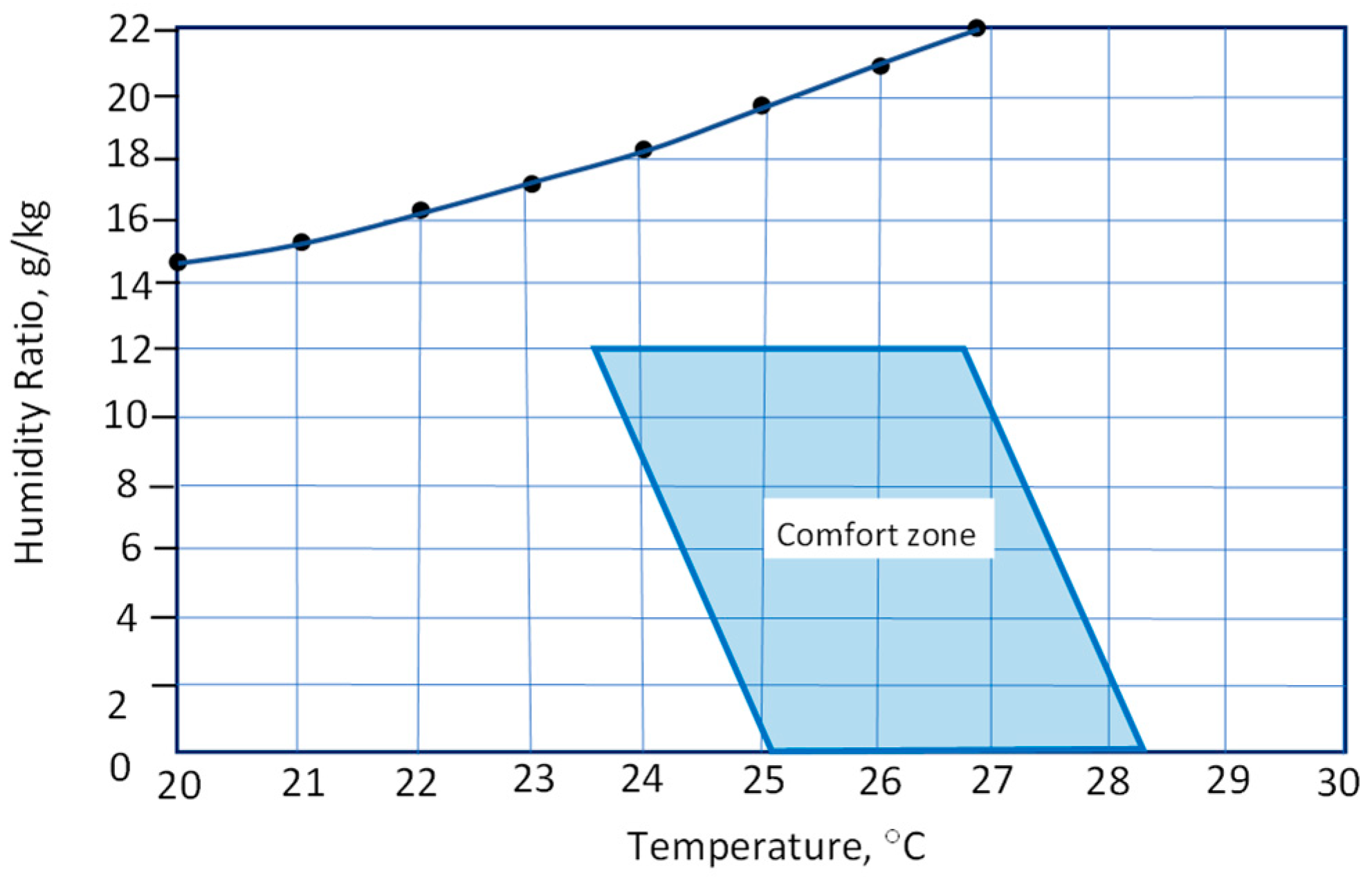
2.1. Thermal Comfort Factors and Requirements in Built Environment

The main aim of an air-conditioning system is to provide thermal comfort and acceptable indoor air quality needed by the occupants for the conditioned space of a built environment. The term thermal comfort is defined as “the condition of mind that expresses satisfaction with the thermal environment” [8]. An acceptable and comfortable thermal environment set by this definition is expected to be provided by the installed air-conditioning system, assuming the built environment is designed such that the system operates in an efficient way. Thermal comfort is affected by the following environmental factors: air temperature, air relative humidity, air relative velocity, and mean radiant temperature. Thermal comfort is also affected by the level of activity and the thermal insulation value of the clothes worn by a person. These two are called the personal factors of thermal comfort [9].
The combined interaction of these environmental and personal factors form the thermal condition in the human mind, which assesses it subjectively. The impact of each factor on thermal comfort has been made possible through the development of the Fanger’s double heat balance equation, which relates these factors using thermodynamic and heat transfer principles [9].
The comfort index derived from this approach is called the predicted mean vote (PMV), which sums up people’s thermal sensation as a degree of warmth or a cool sensation in a 7-point Likert scale, as shown in Figure 1.
The ASHRAE comfort zone for summer (Figure 2) is employed in this paper to analyze the thermal comfort performance/capability of the solid-desiccant rotor-based air-conditioning system. It has left and right temperature boundaries as well as bottom and upper humidity ratio boundaries that define the thermal comfort zone. Application of the summer comfort zone assumes the following: (a) air speed in the room does not exceed 0.2 m/s, (b) clothes worn by the space occupants have clothing insulation of 0.5 clo, (c) occupants are not exposed to direct beam radiation, and (d) occupants are engaged in sedentary activities with a metabolic rate between 1 and 1.3 met.

2.2. Adaptive Approach to Thermal Comfort

Soon after the adoption of Fanger’s heat balance approach by relevant standards, notably the ASHRAE Standard 55-1981 [10] and its subsequent versions, another approach to thermal comfort study emerged, with the main feature being its simple expression of the indoor temperature as a function the outdoor temperature [11,12,13]. As such, it very much simplifies the solution to the Fanger double heat balance equation. It ignores many thermal comfort factors included in the Fanger heat balance equation. In a nutshell, this approach postulates that, basically, people can tolerate the thermal environment more than predicted in the PMV index derived from the heat balance equation. The critical discussion on the strengths and many drawbacks of this approach can be found in Halawa and v. Hoof [14].
The research activities based on this adaptive approach have been commonplace worldwide and have been the basis for the use of natural ventilation for the comfort of people, especially in the tropics (e.g., [15,16,17,18]). However, it should be noted that the seeming suitability of this approach in predicting the acceptable thermal comfort may be somewhat misplaced. While this approach seems to suggest acceptability of higher temperatures for people living in the hot and humid tropics, there are several factors that seem to indicate otherwise or, at least, that this is not necessarily the case.
Firstly, there seems to be a lack of people’s knowledge of temperature levels appropriate for comfort in air-conditioned homes. A survey of air-conditioned homes in Surabaya (Indonesia) and Kuala Lumpur (Malaysia) showed that the average temperature settings are quite low, i.e., 21.6 °C for Surabaya and 22 °C for Kuala Lumpur, respectively [19]. The same study revealed that the lowest room setting temperatures were 16 °C and 15 °C for Surabaya and Kuala Lumpur, respectively. Not surprisingly, people expecting comfort were in fact generally feeling cold or cool, and only 8.1% and 28.6% felt “neutral” in Surabaya and Kuala Lumpur, respectively. The highest setting temperature was 39 °C in a bedroom of a home in Kuala Lumpur. Therefore, in such cases, it was not the failure of the Fanger heat balance approach that “adequately describe comfortable conditions in a hot climate” as seems to be suggested by the authors ([19], p. 141). Anecdotal evidence has also pointed to similar observations in various types of buildings in the tropics.
Secondly, the procurement of air-conditioning systems worldwide, including in the tropics, has been increasing steadily, which runs counter to adaptive-based thermal comfort research. Houses researched in [15] are of naturally ventilated types, and people’s adaptive adjustments include “drinking more water, changing clothes, and taking bath more frequently”. Similar adjustments for office buildings were also mentioned in [17]. This is of course very natural in the absence of much preferred options. However, the natural adjustment approach taken by these people—most of whom still cannot afford to purchase air conditioners—should not be regarded, let alone be set, as their settled approach to attain truly thermally comfortable conditions, nor introduced into thermal comfort standards. These people living in tropical climates would certainly wish to attain much better thermal comfort if they had the economic means and not merely to “reduce thermal discomfort” through “sufficient air movement” [16] or adjustment options observed and reported in [15]. This observation is supported by a recent report of the International Energy Agency which states that “for a given type of climate, the rate of household ownership of ACs rises with economic development and incomes—very quickly in the case of the hottest and most humid countries” ([20], p. 38). Therefore, it can be inferred that these observed natural adjustment options are merely a delayed pursuance of real thermal comfort due to economic unaffordability. Due to this economic affordability issue, the use of air-conditioning systems in many countries is still not prevalent. However, in Indonesia, for instance, a rise in air-conditioning system use in homes was observed [19], and increased household income gives rise to this [21].
Thirdly, changing clothes—one of the adaptive adjustments mentioned in [15]—basically relates to the impact of high air humidity on people’s skin, which blocks the moisture from leaving the skin and results in sweating. While skin stickiness may not be a big issue in home settings where people may just relax, it still entails the change of clothes to avoid further moisture blocking and to gain skin’s renewed feeling of freshness. In the working place such as homes, the impacts of high humidity on productivity has been observed [22,23]. High humidity (RH above 70%) also results in people’s weariness [23].
Reference to this adaptive approach to thermal comfort in this paper merely points to the fact that it has been a popular method frequently mentioned in the research papers dealing with thermal comfort issues in hot/warm and humid regions. Interestingly, or rather ironically, this approach cannot be utilized as a tool to evaluate the thermal comfort performance of air-conditioning systems aimed to resolve the issues in those climatic regions. Its omission of air humidity and velocity in its analysis makes it unsuitable for such an evaluation task.

2.3. Indoor Air Quality

In addition to thermal comfort requirements, indoor air quality is also crucial in providing a healthy environment to the occupants of the built environment. The current COVID-19 pandemic has prompted the World Health Organization (WHO) to provide brief information on the role of, and recommended actions to improve, ventilation in public spaces and buildings [24,25]. The quality of the indoor air is severely affected by the buildup of various gases such as carbon monoxide, volatile organic compounds, microbes such as bacteria and molds, and particulates. These can lead to sick building syndrome and other related health issues. Adequate fresh air supply to the air-conditioned space can help alleviate these issues.
The quantity of fresh air has been found to affect an occupant’s productivity. In high-occupancy-density buildings, an increase in the amount of fresh air increases the occupants’ productivity and satisfaction. In buildings with high-occupancy density such as offices or schools, reduced productivity can be related to dissatisfaction with indoor air quality, while productivity can be improved by increasing the fresh air flow rate [26]. Increased fresh air flow rate supply to classrooms has been found to substantially improve children’s performance in accomplishing school-related work such as reading and solving mathematics problems [27].

3. Overview of Research/Studies on Solid-Desiccant-Based Air-Conditioning

This section discusses various configurations of the solid-desiccant-based air conditioners that have been proposed or investigated in the literature. The next section details the strengths and limitations of these systems. The various configurations observed from the available literature are classified into two broad categories, namely, (1) single-rotor systems and (2) two-rotor systems. Each of the categories has its own subconfigurations.

3.1. Single-Rotor System Configurations

3.1.1. Single Rotor—Basic Configuration

Figure 3 shows a sketch of a simple configuration of a desiccant-based air-conditioning system [7]. The main components of the system are a desiccant rotor, a heat-recovery unit, two humidifiers (direct evaporative coolers), a regenerator, and supply and exhaust fans.
The typical psychrometric processes involved in such a system are shown in Figure 4. Ambient air enters the desiccant wheel/rotor, where some of its moisture is removed but its temperature is raised (1–2). The air then passes through the heat-recovery exchanger, where it is sensibly cooled (2–3). The direct evaporative cooler further cools the air (3–4) but increases its moisture content again before it is drawn by a supply fan into the conditioned space. Air pre-heating (4–5) only applies to cold climates [7].
On the exhaust side, the return air from the conditioned space (6)—with some small increase in temperature and humidity—is passed through another evaporative cooler, which brings down its temperature but increases its moisture content (6–7). In the heat-recovery exchanger, the air is preheated at a constant humidity ratio (7–8). The air temperature is significantly increased in the heat regeneration exchanger (8–9) before it enters the desiccant rotor. In the desiccant rotor, the entering hot air removes the moisture from the desiccant (regeneration process 9–10) to enable it to absorb moisture when this part of the rotor passes the supply side.
The heat to the regenerator in Figure 3 stored in a hot water tank is supplied by an array of solar collectors. However, in practice, any thermal energy source can be used, providing the regeneration temperature requirements are met.

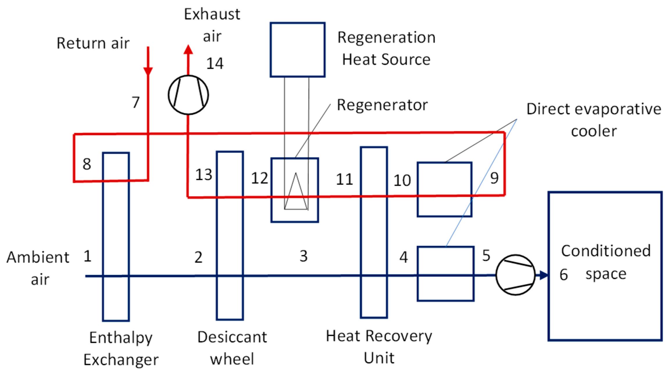
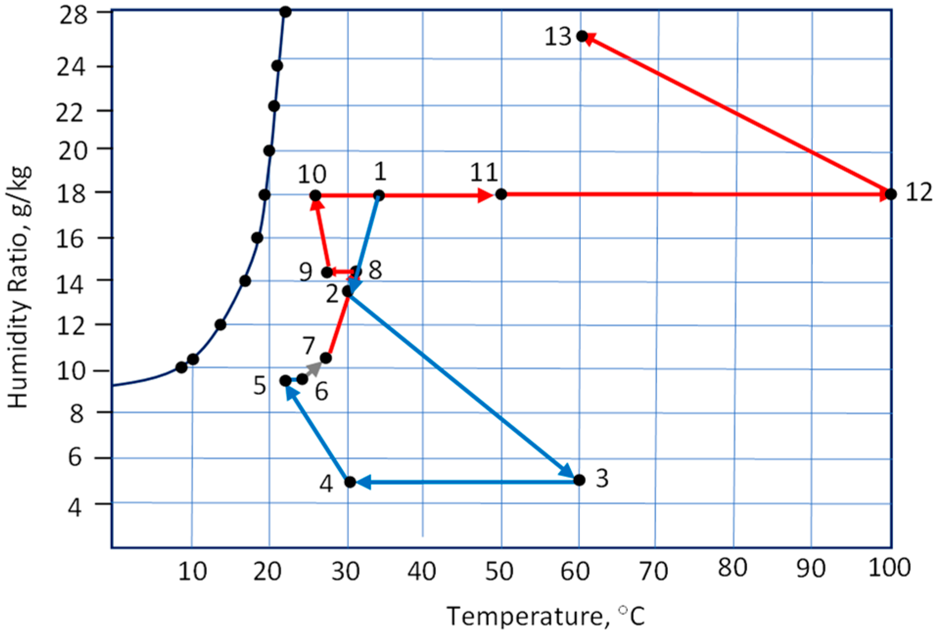
3.1.2. Simple Configuration with an Enthalpy Exchanger

According to Henning [7], the system configuration in Figure 3 is only workable in temperate climates. For more humid climates, further dehumidification is required. One such configuration is similar to that in Figure 3 but with the addition of an enthalpy exchanger before the desiccant rotor, as shown in Figure 5.
Figure 6 shows the psychrometric processes of the system whose configuration is depicted in Figure 5. The enthalpy exchanger pre-dehumidifies the air and slightly reduces its temperature (1–2). Each of the remaining processes in Figure 6 is self-explanatory. It is worth noting that for more humid climates, the regeneration temperature needs to be raised (to point 12), as shown in Figure 6.
The performance of the system with this component operating in a subtropical or tropical climate has been evaluated. In general, the enthalpy exchanger increases the system dehumidification performance. However, the system does not perform well in very humid climates, such as in Darwin [28].
The term two-stage was used in [29] to describe the system developed; however, this should fall into the single-configuration category discussed in this section as the first wheel is basically an enthalpy exchanger.

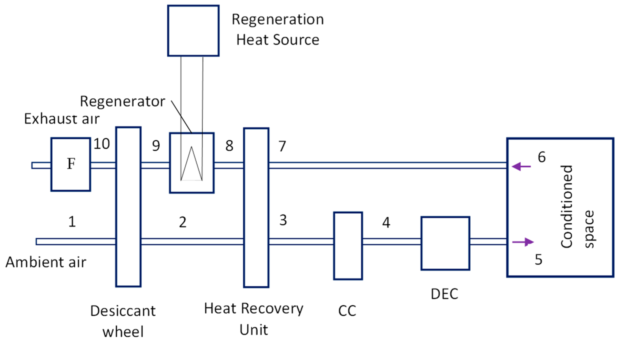
3.1.3. Single-Rotor System with Cooling Supplied by Chilled Water

In this configuration, the single desiccant rotor provides cooling and dehumidification (1–2), while precooling and postcooling are accomplished by chilled water running through two cooling coils. The first chilled water coil replaces the enthalpy exchanger in Figure 5 and is installed before the desiccant rotor. The second chilled water coil is placed after the heat recovery unit and replaces the direct evaporative cooler on the supply side [7]. The system components on the exhaust side are the same as in Figure 6. The replacement of the direct evaporative cooler with the chilled water coil improves the dehumidification capability of the system. Despite this improvement, single-stage dehumidification systems are still not able to cope with high latent loads in warm/hot and very humid climates.
A variation of this configuration [30] is shown in Figure 7, where air is cooled as it passes through the cooling coil (CC) and a direct evaporative cooler (DEC).

3.2. Two-Stage Dehumidification System

In a two-stage solid-desiccant evaporative air-cooling (SDEAC) system, two desiccant wheels are placed in series to bring down air humidity in two stages. In each stage, the dehumidification is accompanied by increased air temperature. Therefore, each dehumidification process is also accompanied by sensible cooling of air in a heat-recovery wheel. The advantage of this over the single stage is its increased dehumidification capability, which makes it potentially suitable to operate in humid climates. On the other hand, its improved dehumidification capability comes at a cost, that is, an increased number of conditioning components, which directly affects its economic attractiveness and increased need for regeneration heat.

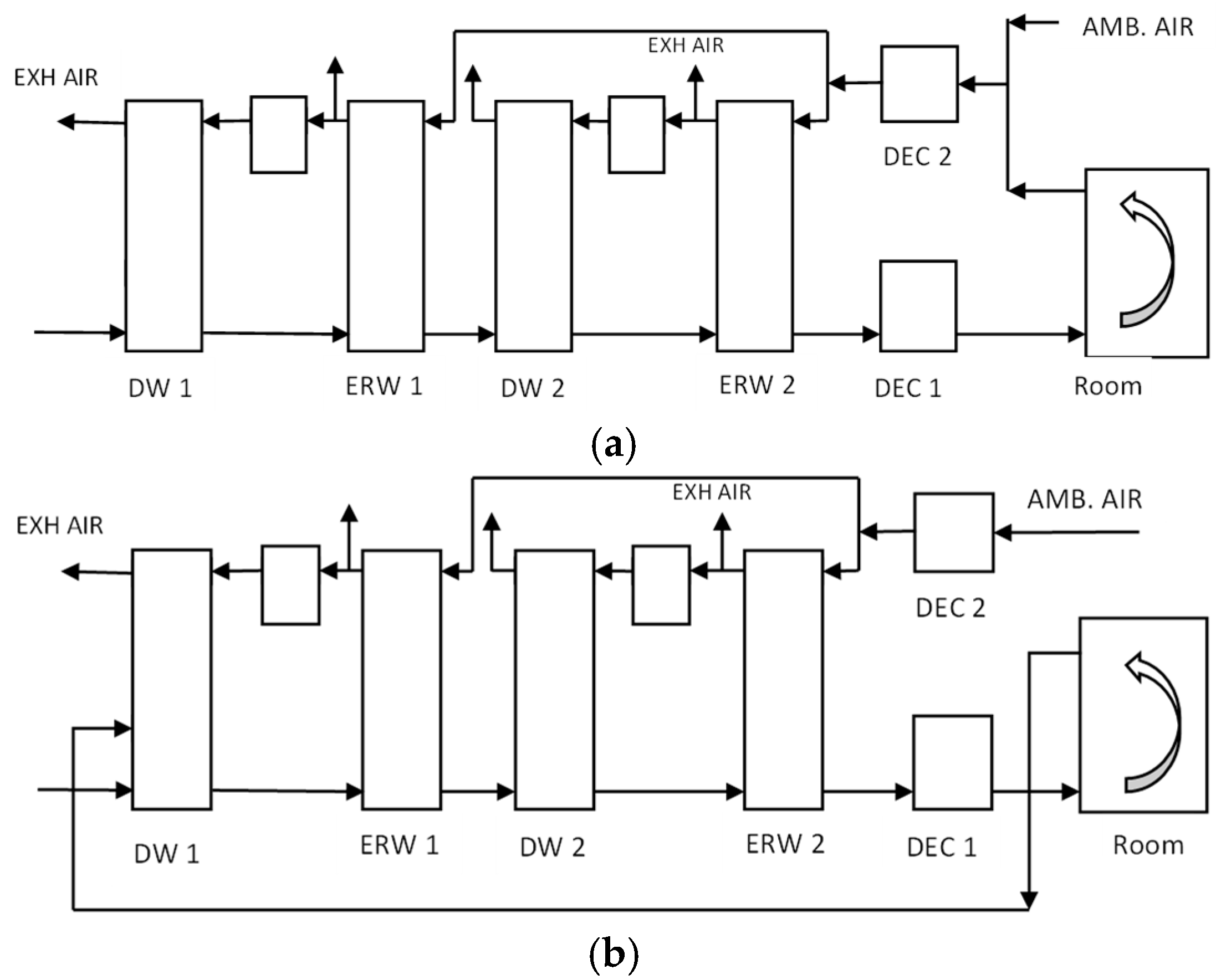
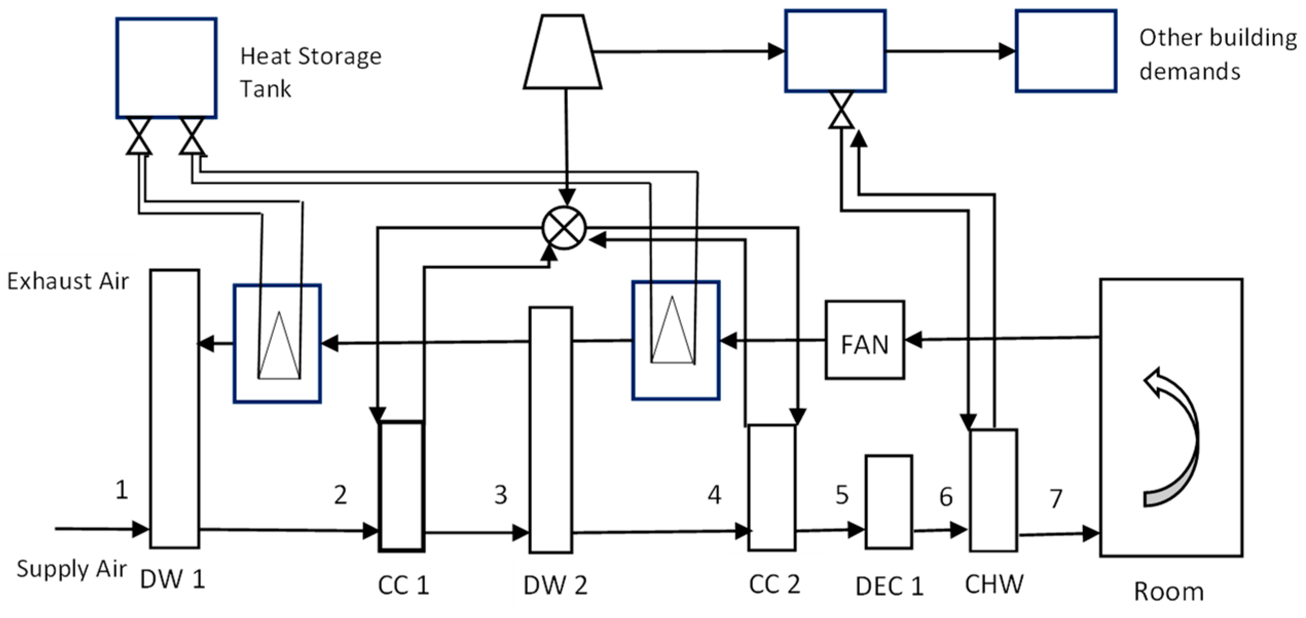
3.2.1. Two-Stage Dehumidification Systems with Ventilation and Recirculation Modes

Figure 8 shows a SDEAC system with (a) a ventilation mode and (b) a circulation mode [31]. In the ventilation mode (also called an open-cycle configuration), ambient air is fed to the desiccant wheel on the supply side (Figure 8a). In the recirculation configuration (also called a closed-cycle configuration), return air from the room is fed to the desiccant wheel on the supply side (Figure 8b). These configurations were able to provide acceptable humidity levels in an air-conditioned room operating in Kuala Lumpur [31]. Both ventilation and recirculation modes can deliver an average room humidity ratio of 11 g/kg and average room temperatures of 27.3 °C (ventilation mode) and 27 °C (recirculation mode), respectively. These conditions were accomplished employing regeneration temperatures of 82 °C (stage 1) and 80 °C (stage 2) in ventilation mode, and 80 °C (stage 1) and 50 °C (stage 2) in recirculation mode. Yet, the thermal COP of the system with ventilation mode is much higher (at 1.06) compared to the system with recirculation mode (0.43). The electrical COPs of the systems were not reported.
It is interesting to observe in the computer modelling reported in [31] that the humidity ratio of air leaving the second desiccant rotor is 5 g/kg and constant, much lower than the resulting average room humidity ratio of 11 g/kg. Even with significant room latent load, such a value is still impressively low. In other words, the system over-dehumidifies the air. However, this is not surprising given the fact that after leaving the second rotor and energy recovery wheel 2 (ERW2), the air undergoes rehumidification in a direct evaporative cooler (DEC 1) before it is supplied to the space.

3.2.2. Two-Stage Dehumidification System with Chilled Water as the Cooling Medium

In the configurations mentioned previously for both single- and double-rotor systems, the cooling of air is carried out in the evaporative coolers and energy-recovery wheels. Another method of cooling is by tapping coolth energy from an existing chilled water system [32], such as that shown in the schematic in Figure 9 and psychrometric processes in Figure 10. The figures show the cooling components of the desiccant-based solar-assisted trigeneration system. On the supply side, air is heated and dehumidified in the first desiccant rotor (1–2). Air then cools sensibly as it passes the cooling coil that receives water from a cooling tower (2–3). Further dehumidification is attained in the second desiccant rotor, which also raises the air temperature (3–4). The heated air is cooled in the second chilled water coil unit (4–5), and final cooling is accomplished using a direct evaporative cooler accompanied by an increase in the air humidity ratio. Further cooling, if required, is supplied by a chilled water coil installed after the evaporative cooling process. The cooling process 6–7 was not depicted in the psychrometric processes of [32], and therefore, it cannot be inferred whether it is a sensible process (horizontal line to the left of point 6) or cooling involving dehumidification.
There are many other configurations of the solid-desiccant rotor-based air conditioners apart from those discussed above, some of which can be found in review papers on the subject [33,34,35]. However, the variations in those configurations are on the placement of heat exchangers and/or cooling components and the sources of cooling on the supply side and the regeneration heat on the exhaust side. One example of this is the analytical/optimization work whereby an indirect evaporative cooler was used to cool the air leaving the desiccant wheel [36]. The impacts of various parameters on the system performance were quantified for a particular design, and therefore the validity of the findings could not be generalized. It is worth commenting on the values of the humidity ratio of air leaving the desiccant wheel in the study, which depend on the length of the rotor. The shortest rotor of 0.1 m length (Ld) results in an outlet humidity ratio mostly above 12 g/kg for a range of rotational speeds, which makes it unsuitable for dehumidification. The second rotor with 0.2 m length is able to dehumidify air below 12 g/kg but above 11 g/kg for rotational speeds above five rotations per hour. The longest rotor (Ld = 0.4 m) gives the best dehumidification; however, this results in increased fan electrical consumption. The trends of the findings of this study are in agreement with the numerical and experimental work of Yamaguchi and Saito [37]. However, in the latter, the impact of regeneration temperature on the outlet humidity ratio of air leaving the rotor was presented in detail. Interestingly, these findings show that even at a regeneration temperature as high as 80 °C, the lowest value of the outlet humidity ratio is still around 13.8 g/kg at a rotational speed of 80 rph. While high regeneration temperature boosts the dehumidification capability of the rotor, it also results in an increased process outlet temperature, which requires more cooling energy. The above values were based on the air inlet humidity ratio of 19.5 g/kg. Such a value is a normal occurrence in the tropics, and higher values are also not uncommon.

4. Potential Advantages and Drawbacks of the Desiccant-Based Air-Conditioning System

Given the background of thermal comfort and indoor air quality requirements discussed in Section 2 and the main configurations of the solid-desiccant rotor-based air conditioners discussed in Section 3, this section focuses on the potential advantages and drawbacks of these systems as alternatives to the conventional vapor-compression-based air-conditioning systems they are supposed to replace.

4.1. Potential Advantages

One of the earliest reviews of solid-desiccant cooling systems [38] summarizes the potential advantages of this technology as follows: (1) no impact on the ozone layer from air and water, which are the working fluids of these systems, (2) reduced reliance on electrical energy to provide cooling and therefore reduced use of fossil fuel, (3) improved indoor air quality, (4) simplified system construction and maintenance due to low working pressure, and (5) for systems installed in cold/temperate climates which require both heating and cooling, the need for a separate heating furnace can potentially be eliminated. One other potential advantage of these systems not mentioned in the above list but which has appeared in previous sections of this paper is better thermal comfort in conditioned spaces.
It should be noted that advantage (3) relates to the fact that air treated using these systems is normally fresh (ambient) air. The recirculation cycle that admits return air from the conditioned space to the system’s supply side has been found to be less effective, i.e., has lower COP than the ventilation (fresh air) cycle [31,39].
Many other reviews that followed, including the recent ones (e.g., [40,41,42]), basically point to the same potential advantages. Yet, the potential advantages discussed above have not been clearly demonstrated to date in the form of successful installations and operations with convincing thermal energy and thermal comfort performance outcomes. The claimed advantages appear mainly as various results from numerical and or analytical studies on various system configurations.
Furthermore, most research work has failed to establish a benchmark through which a fair “comparison is being made between different technologies and systems” ([43], p. 254). To date, two main performance indices often employed in the performance assessment are the electrical COP and thermal COP. The main drawback of these indices is the lack of common performance reference between the technologies being compared. For instance, in calculating the thermal COP of a desiccant system, it is normally assumed that the space temperature setting is higher than normally applied to a space conditioned by a refrigerative system (e.g., 27 °C and 25 °C). This is because, in general, the air mass flow rate of supply air to the conditioned space is higher for desiccant systems than that using the conventional refrigerative system. This will result in a different space cooling load which in turn affects the COP of both systems. To overcome this kind of issue, Brown and Domanski [43] proposed the application of exergetic efficiency, Φ, as a performance index derived from the first and second Laws of thermodynamics. This concept, however, is not as straightforward as it appears to be. While this index can properly account for the energy performance of the systems being compared from a thermodynamic standpoint, it may also miss the aspect of other kinds of performance related to the thermal comfort delivery of the systems. For instance, from a thermal comfort point of view, a 27 °C space temperature with slightly higher air speed is equivalent to 25 °C with low air speed based on the PMV index derived from the Fanger heat balance equation [8,9,10]. Nevertheless, this proposal [43] should awaken researchers to find more acceptable performance indices for comparing competing technologies, in particular, in comparing the new emerging technologies against the more established ones, so that the evaluation methods used will not favor the former or vice versa.
It may take some more time to witness the real installations of these systems with claimed good performances demonstrated. The following section explains why such potential advantages will never eventuate.

4.2. Drawbacks

4.2.1. Inevitable Heating of Air While Being Dehumidified

The principal operation of the desiccant wheel inevitably raises the air temperature as it passes through the supply side of the desiccant-attached surface to expel the moisture from the desiccant. This process approximately occurs along a wet-bulb temperature line [36,44,45] and runs counter to the goal of cooling the air. This disadvantage has been realized and raised in [7,46]. The proposed solution to get around this issue is the development of a heat exchanger with sorptive capability such as the “ECOS” (evaporatively cooled sorptive-coated cross-flow heat exchanger) [46], which replaces the desiccant rotor altogether. This novel design has been developed for small applications and is still in the early stage. Similar concepts can be found elsewhere [47,48]. This inevitable and counterintuitive heating of air requires cooling (see Section 3) with the consequential addition of a new cooling component.

4.2.2. Need for Desiccant Regeneration and Low Thermal COP Paradox

The reheating of the desiccant, normally called regeneration, after it adsorbs the moisture from the air on the supply side requires a significant amount of heat. This heat requirement poses a significant challenge to the system to compete economically with conventional systems [48]. Most researchers recommend the use of solar energy or waste heat as the heat source of this regeneration. This is understandable, as the COP of such a system is quite low, from as low as 0.21 to as high as 0.65 [28,31]. On the use of solar energy as the regeneration heat source, one should bear in mind that due to its nature of hourly availability even during the sunniest days, solar energy is not an ideal fit for this purpose. Also, to add to the paradox, it is the requirement of this significant amount of regeneration heat that makes the thermal COP of these systems unimpressively low.

4.2.3. Limited Options for Regeneration Heat Sources

Any initiative for improving the system performance by providing a heating fossil-fuel backup runs counter to the original idea of the technology’s development. As such, this system is not suitable to be driven by conventional heating systems such as gas heaters. While waste heat can be used, heat-recovery devices are still not readily available in many parts of the world. Therefore, the only prospective thermal energy source suitable for driving this system is solar energy through solar thermal collectors. However, the energy efficiency aspect of these systems has been overlooked in some countries such as Australia, where the main focus is on boosting renewable energy production [49,50]. Furthermore, there seems to be an increasing popularity of rooftop solar PV systems in recent years (see, for instance, [51]), which directly eases the pressure on people to avoid the use of conventional refrigerative systems for the sake of the environment. This condition applies in particular to regions having abundant sunshine.
Using solar collector arrays to provide heat for solid-desiccant regeneration means this technology cannot be prospective for residential applications, where some conditioned spaces (i.e., bedrooms, living rooms, etc.) require cooling during the night. This is because solar thermal collectors cannot supply heat to the regenerator during the night. For nonresidential buildings such as wet markets [52,53] and supermarkets, the nature of solar energy availability makes it impossible to run this system using solar energy alone due to its nature of availability. To effectively dehumidify the supply air, a minimum regeneration temperature must be guaranteed to avoid thermal discomfort. According to [54], a regeneration temperature below 80 °C (353 K) results in a significant reduction in dehumidification capability due to lack of water desorption.

4.2.4. Limited Options for Reliable Cooling

The counterintuitive heat requirement for desiccant regeneration and for cooling the heated air encourages researchers to find reliable and suitable options for cooling the air after it undergoes heating in the supply passage of the desiccant rotor to reach an acceptable supply temperature. As discussed in Section 3, heat-recovery exchangers have been one of the many popular options. However, this has not been so effective in attaining the required cooling. Therefore, some of the system configurations presented involve the tapping of cooling energy from existing cool water from a cooling tower or chilled water from a chiller plant. This seems a reasonable option. However, unless the existing chilled water plant derives its energy from non-fossil fuel sources, which, to date, is still not the case, this option again runs counter to the initial objective of the development of this technology. Furthermore, this option will certainly lower the system’s overall performance and increase the capital cost through the addition of heat exchange and pumping components.
Combining the desiccant-based system with an existing chilled-water system may not be readily practicable, for instance, if the existing chilled-water system has no extra capacity. Another issue with such an arrangement is that failure of the latter directly affects the desiccant-based system.

4.2.5. Low Electrical COP

Solid-desiccant-based systems still use electrical energy to power their various components. As such, they should consume much less electrical energy than their refrigerative counterparts. This, however, has not been well demonstrated through the energy performance of these systems. A recent numerical study shows that the annual electrical COP of such a system is only as high as 4.8 for the less humid city of Brisbane, while it is 2.9 for the warm and humid city of Darwin [28]. With generally low thermal COPs, any marginal gain from saving electricity may not be worth it. However, a special type of indirect evaporative cooler called the dew point cooler (DPC), with an average COP of up to 9 [55,56], has been found to be able to deliver cooling to regions with temperate climates and climates with mild humidity. The DPC technology has also been used to enhance the performance of a CO2 refrigeration systems in warm and hot climates [57,58].

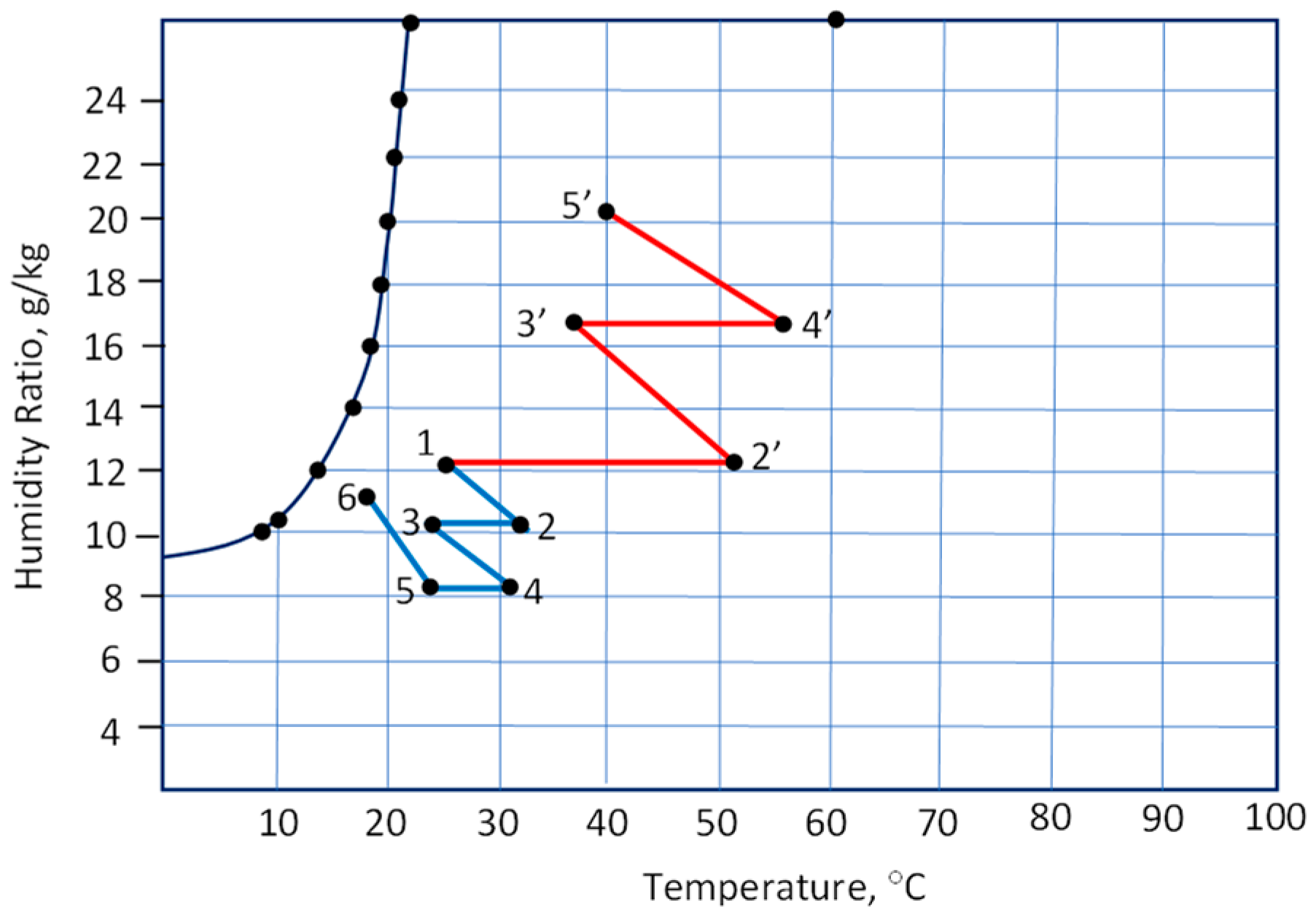
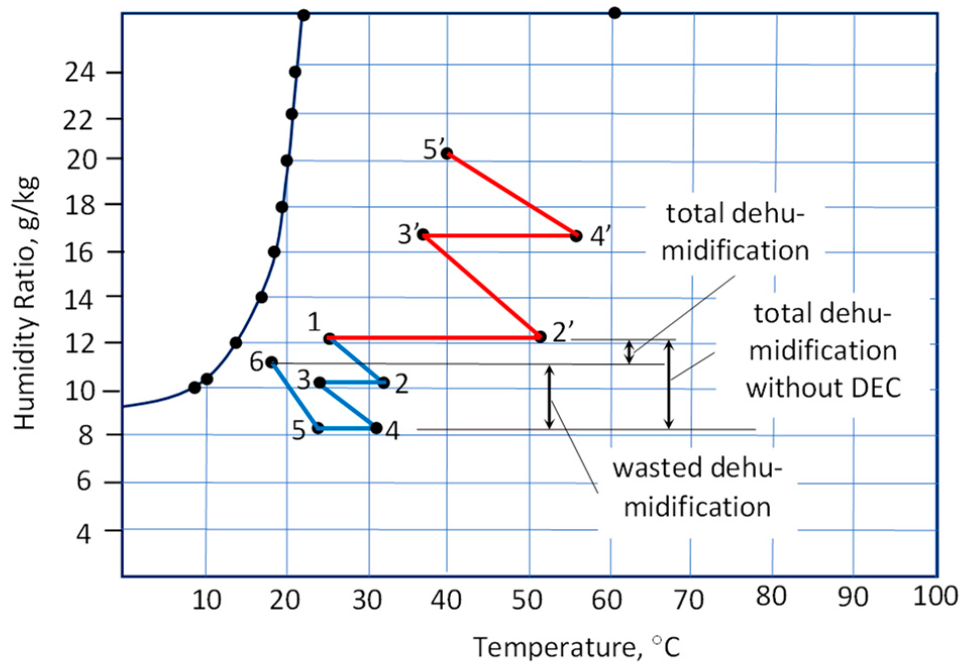
4.2.6. Counterintuitive Addition of Moisture to Air during the Evaporative Cooling Process

Many researchers have presented desiccant-based configurations where the final cooling is provided by the direct evaporative cooler (see Section 3). This type of cooling system necessitates the addition of moisture in the air it treats to have a cooling effect. This rehumidification issue was recognized as early as 2005 [59]. While this stand-alone system can be considered for dry climates, its introduction as a component of a desiccant-based cooling systems in humid climates is impractical, if not impossible. In humid climates, it does not have a suitable driving force to cool the air using evaporative cooling principles. And even if such a configuration works in humid climates, its humidifying nature is very counterintuitive. Figure 11 is a reproduction of Figure 10, made to show the counterintuitive concept of introducing a direct evaporative cooler in a desiccant-based cooling system. The ambient air entering the system at point (1) exits the system and enters the conditioned space at point 6. The sensible cooling from 5 to 6 is carried out at the loss of dehumidification equal to HR6–HR5. This is, of course, counterintuitive to the very goal of introducing the desiccant-based air-conditioning system.

4.2.7. Thermal Comfort Performance Delivery Questioned

Many studies (e.g., [60,61,62,63,64]) overlooked the thermal comfort delivery capability of the systems in the analysis. Thermal performance alone, expressed as electrical and thermal COPs, presents only one side of the coin and therefore provides an incomplete assessment of the system. In the warm to hot and humid tropics, the humidity issue poses special challenges to air-conditioning systems.
The numerical studies for single-rotor desiccant wheels have mixed results. One study [60,61,62] presented an encouraging result for systems operating in the humid city of Darwin, Australia, in terms of a higher COP. In the study, the thermal comfort conditions in the conditioned space seemed to have been overlooked. On the other hand, two separate studies [28,30] have shown that the single-rotor system was not able to satisfy the humidity level requirements of humid cities such as Kuala Lumpur (Malaysia) and Darwin (Australia). For Darwin, a single-rotor system with enthalpy exchanger can only satisfy a humidity level (refer to comfort zone of Figure 2) in the range of 54–63% of the conditioning time [28]. This is despite added dehumidification capability due to the enthalpy exchanger compared to the basic system configuration employed in [60,61,62]. For Kuala Lumpur, in using a system with a basic configuration, the humidity ratio of supply air always falls beyond the 12 g/kg boundary. The humidity level of supply air only improves using two-stage dehumidification [31].
Apart from the drawbacks listed above, other issues that have been identified include initial capital cost and lack of familiarity of proper installation and maintenance due to relative novelty and complexity [30].

5. Conclusions and Future Research Directions

The past 30 years have witnessed growing interest in research and development of desiccant-based cooling systems, with the solid-desiccant rotor-based cooling system being one of the most popular researched. This paper has briefly presented the most common configurations of these systems. The following are highlights of this critical overview:
  • The solid-desiccant rotor as the core component of this technology to provide the air dehumidification suffers from significant thermal performance degradation due to the need for (a) significant heat for the desiccant regeneration and (b) recooling of air as it exits the rotor.
  • The initial and noble case for reducing reliance on the electricity powered by fossil fuels suffers setbacks due to the lack of alternative reliable fossil-free energy sources to provide the regeneration heat. This is further exacerbated by the generally low system thermal performance.
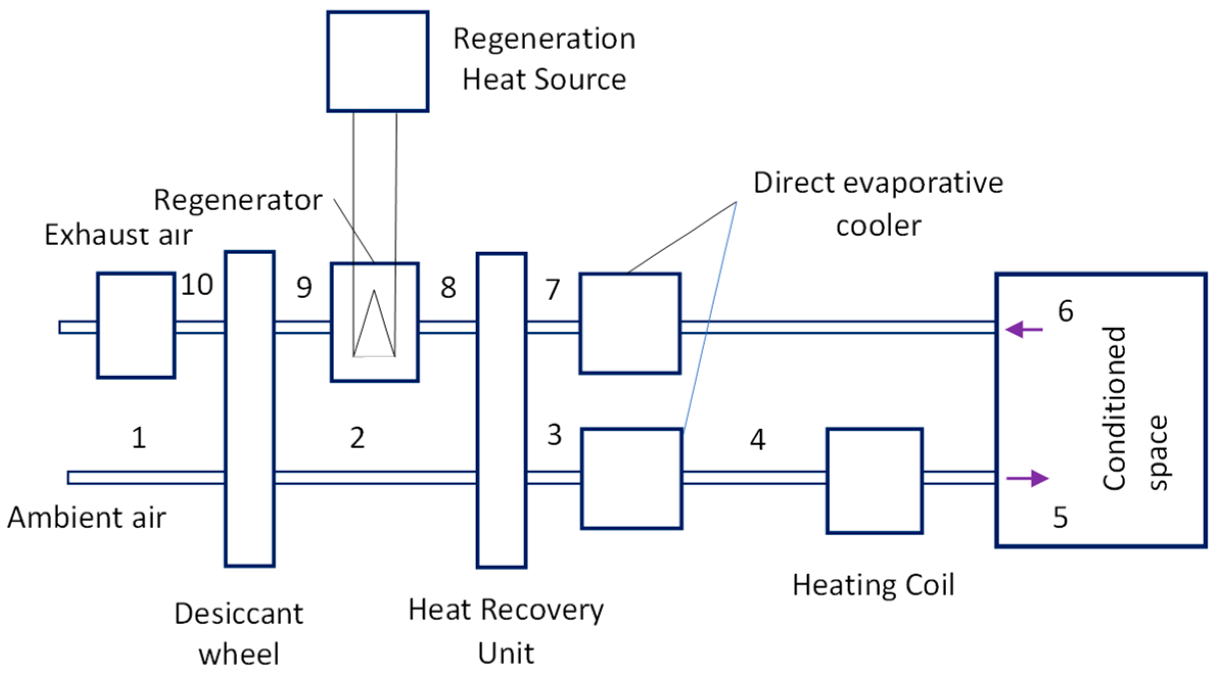
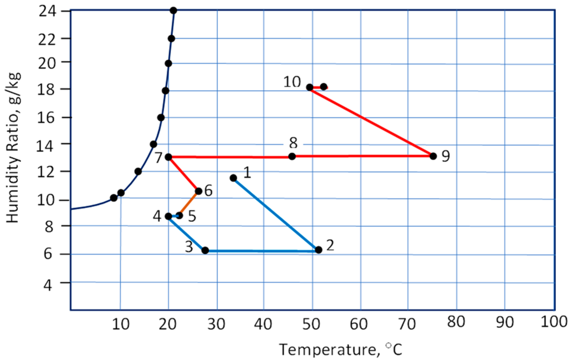
  • Inclusion of direct evaporative coolers in many system configurations practically nullifies the initial goal of dehumidifying the air before it is admitted to a conditioned space. The use of dew point coolers that do not humidify the air as the substitute may potentially improve the system thermal performance. However, further studies are required to evaluate this potential.
  • The points mentioned above seem to have led to the development of the solid-desiccant rotor-cooling technology with more components that thermally nullify each other’s roles in bringing about air conditions suitable for the thermal comfort of occupants of an air-conditioned space.
  • Recent studies have started turning away from open-cycle sorption cooling with the desiccant rotor being one of its core components.
  • Currently, thermal and electrical COPs are the main indices for evaluating performance of the desiccant-solid systems. However, these indices lack common references when comparing competing technologies. Widely acceptable performance indices need to be developed to enable a proper evaluation of the viability of this technology against its competing counterparts, in particular conventional vapor-compression air-conditioning systems. These indices should take into account the thermal and electrical performance as well as the thermal comfort delivery capability of each technology.
  • A recent surge in popularity of PV systems has provided the option of achieving thermal comfort from a cleaner energy source using conventional vapor-compression refrigeration technologies.
  • A breakthrough in the solid-desiccant rotor cooling system, component design, and performance improvement seems the only pathway for this technology to maintain its relevance. To date, this has not been convincingly demonstrated.

Author Contributions

E.H. initiated the draft of this paper and developed the major ideas conveyed in the paper. F.B. provided constructive and critical inputs throughout the stages of manuscript development. All authors have read and agreed to the published version of the manuscript.

Funding

Authors obtained no funding from any source for this review work.

Data Availability Statement

No new data were created or analyzed in this study. Data sharing is not applicable to this article.

Conflicts of Interest

The authors declare no conflict of interest.

References

  1. Perez-Lombard, L.; Ortiz, J.; Pout, C. A review on buildings energy consumption information. Energy Build. 2008, 40, 394–398. [Google Scholar] [CrossRef]
  2. Li, X.W.; Wen, J. Review of building energy modeling for control and operation. Renew. Sustain. Energy Rev. 2014, 37, 517–537. [Google Scholar] [CrossRef]
  3. Shaw, A.; Luxton, R.E. A comprehensive method of improving part load air conditioning performance. ASHRAE Trans. 1988, 94, 442. [Google Scholar]
  4. Sekhar, S.C.; Luxton, R.E.; Shaw, A. Design methodology for cost effective air conditioning in humid climates. In Proceedings of the ASHRAE Far East Conference on Air conditioning in Hot Climates, Kuala Lumpur, Malaysia, 25–28 October 1989; ASHRAE: Atlanta, GA, USA, 1989. [Google Scholar]
  5. Sekhar, S.C. Life Cycle Design of Dehumidifiers in Air Conditioning. Ph.D. Thesis, University of Adelaide, Adelaide, Australia, 1990. [Google Scholar]
  6. Çengel, Y.A.; Boles, M.A.; Kanoģlu, M. Thermodynamics: An Engineering Approach, 9th ed.; McGraw-Hill Education: New York, NY, USA, 2018. [Google Scholar]
  7. Henning, H.-M. Solar assisted air conditioning of buildings—An Overview. Appl. Therm. Eng. 2007, 27, 1734–1749. [Google Scholar] [CrossRef]
  8. ANSI/ASHRAE Standard 55-2017; Thermal Environmental Conditions for Human Occupancy. ASHRAE Inc.: Atlanta, GA, USA, 2017.
  9. Fanger, P.O. Thermal Comfort: Analysis and Applications in Environmental Engineering; McGraw Hill Book Company: New York, NY, USA, 1970. [Google Scholar]
  10. ANSI/ASHRAE Standard 55-1981; Thermal Environmental Conditions for Human Occupancy. ASHRAE Inc.: Atlanta, GA, USA, 1981.
  11. Nicol, J.F. Adaptive comfort—Editorial. Build Res. Inf. 2011, 39, 105–107. [Google Scholar] [CrossRef]
  12. de Dear, R.J.; Brager, G.S. Towards an adaptive model of thermal comfort and preference. ASHRAE Trans. 1998, 104, 145–167. [Google Scholar]
  13. Nicol, J.F.; Humphreys, M.A. Adaptive thermal comfort and sustainable thermal standards for buildings. Energy Build. 2002, 34, 563–572. [Google Scholar] [CrossRef]
  14. Halawa, E.; van Hoof, J. The adaptive approach to thermal comfort: A critical overview. Energy Build. 2012, 51, 101–110. [Google Scholar] [CrossRef]
  15. Feriadi, H.; Wong, N.H. Thermal comfort for naturally ventilated houses in Indonesia. Energy Build. 2004, 36, 614–626. [Google Scholar] [CrossRef]
  16. Bhikhoo, N.; Hashemi, A.; Cruickshank, H. Improving Thermal Comfort of Low-Income Housing in Thailand through Passive Design Strategies. Sustainability 2017, 9, 1440. [Google Scholar] [CrossRef]
  17. Damiati, S.A.; Zaki, S.A.; Rijal, H.B.; Wonorahardjo, S. Field study on adaptive thermal comfort in office buildings in Malaysia, Indonesia, Singapore, and Japan during hot and humid season. Build Environ. 2016, 109, 208–223. [Google Scholar] [CrossRef]
  18. Mishra, A.K.; Ramgopal, M. An adaptive thermal comfort model for the tropical climatic regions of India (Köppen climate type A). Build Environ. 2015, 85, 134–143. [Google Scholar] [CrossRef]
  19. Ekasiwi, S.N.N.; Majid, N.H.A.; Hokoi, S.; Oka, D.; Takagi, N.; Uno, T. Field survey of air conditioner temperature settings in hot, humid climates, part 1: Questionnaire results on use of air conditioners in houses during sleep. J. Asian Archit. Build. Eng. 2013, 12, 141–148. [Google Scholar] [CrossRef]
  20. Dean, B.; Dulac, J.; Morgan, T.; Remme, U.; Motherway, B. The Future of Cooling: Opportunities for Energy-Efficient Air Conditioning; International Energy Agency: Paris, France, 2018; Available online: https://www.iea.org/futureofcooling/ (accessed on 20 December 2021).
  21. Mori, H.; Shigekane, H.; Kubota, T.; Arethusa, M.T. Comparative analysis of factors influencing window-opening behavior in residential buildings of Southeast Asia. In Proceedings of the International Joint-Conference Senvar-Inta-Avan 2015 “Wisdom of the Tropics: Past Present & Future”, Johor, Malaysia, 24–26 November 2015; pp. 144–153. [Google Scholar]
  22. Wyndham, C. Thermal comfort in the hot humid tropics of Australia. Br. J. Ind. Med. 1963, 20, 110–117. [Google Scholar] [CrossRef]
  23. Tsutsumi, H.; Tanabe, S.; Harigaya, J.; Iguchi, Y.; Nakamura, G. Effect of humidity on human comfort and productivity after step changes from warm and humid environment. Build Environ. 2007, 42, 4034–4042. [Google Scholar] [CrossRef]
  24. WHO Website. Q&A: Ventilation and Air Conditioning in Public Spaces and Buildings and COVID-19. 2020. Available online: https://www.who.int/news-room/q-a-detail/q-a-ventilation-and-air-conditioning-in-public-spaces-and-buildings-and-covid-19 (accessed on 7 September 2020).
  25. GHHIN Website. Heat and COVID-19 Information Series—Issues for Heat Action Planners and City Authorities—Air Conditioning and Ventilation Global Heat Health Information Network Website. 2020. Available online: http://www.ghhin.org/heat-and-covid-19/ac-and-ventilation (accessed on 7 September 2020).
  26. Kosonen, R.; Tan, F. The effect of perceived indoor air quality on productivity loss. Energy Build. 2004, 36, 981–986. [Google Scholar] [CrossRef]
  27. Wargocki, P.; Wyon, D.P.; Matysiak, B.; Irgens, S. Supply rate on the performance of school work by children. In Proceedings of the 10th International Conference on Indoor Air Quality and Climate, Beijing, China, 4–9 September 2005; Volume 1, pp. 368–372. [Google Scholar]
  28. Narayanan, R.; Halawa, E.; Jain, S. Dehumidification capabilities of a Solid Desiccant Evaporative Cooling System with an Enthalpy Exchanger Operating in Subtropical and Tropical Climates. Energies 2019, 12, 2704. [Google Scholar] [CrossRef]
  29. Meckler, G. Two-Stage Desiccant Dehumidification in Commercial Building HVAC Systems. ASHRAE Trans. 1989, 95, 1116–1123. [Google Scholar]
  30. Ruivo, C.R.; Hernández, F.F.; López, J.M.C. Influence of the desiccant wheel effectiveness method approaches, with fix and variable effectiveness parameters, on the performance results of an airport air-conditioning system. Energy Convers. Manag. 2015, 94, 458–471. [Google Scholar] [CrossRef]
  31. Dezfouli, M.M.S.; Mat, S.; Pirasteh, G.; Sahari, K.S.M.; Sopian, K.; Ruslan, M.H. Simulation analysis of the four configurations of solar desiccant system using evaporative cooling in tropical weather in Malaysia. Int. J. Photo Energy 2014, 2014, 843617. [Google Scholar] [CrossRef]
  32. Hands, S.; Sethuvenkatraman, S.; Peristy, M.; Rowe, D.; White, S. Performance analysis & energy benefits of a desiccant based solar assisted trigeneration system in a building. Renew Energy 2016, 85, 865–879. [Google Scholar]
  33. Sultan, M.; El-Sharkawyb, I.I.; Miyazaki, T.; Saha, B.B.; Koyama, S. An overview of solid desiccant dehumidification and air conditioning systems. Renew. Sustain. Energy Rev. 2015, 46, 16–29. [Google Scholar] [CrossRef]
  34. Rafique, M.M.; Gandhidasan, P.; Rehman, S.; Al-Hadhrami, L.M. A review on desiccant based evaporative cooling systems. Renew. Sustain. Energy Rev. 2015, 45, 145–159. [Google Scholar] [CrossRef]
  35. Jani, D.B.; Mishra, M.; Sahoo, P.K. Solid desiccant air conditioning—A state of the art review. Renew. Sustain. Energy Rev. 2016, 60, 1451–1469. [Google Scholar] [CrossRef]
  36. Goldworthy, S.; White, S. Optimisation of a desiccant cooling system design with indirect evaporative cooler. Int. J. Refrig. 2011, 34, 148–158. [Google Scholar] [CrossRef]
  37. Yamaguchi, S.; Saito, K. Numerical and experimental performance analysis of rotary desiccant wheels. Int. J. Heat Mass Transf. 2013, 60, 51–60. [Google Scholar] [CrossRef]
  38. Waugaman, D.G.; Kini, A.; Kettleborough, C.F. A Review of Desiccant Cooling Systems. J. Energy Resour. Technol. 1993, 115, 1–8. [Google Scholar] [CrossRef]
  39. Kettleborough, C.F.; Ullah, M.R.; Waugaman, D.G. Desiccant Cooling Systems—A Review. In Proceedings of the Third Symposium on Improving Building Systems in Hot and Humid Climates, Arlington, TX, USA, 18–19 November 1986; Available online: https://oaktrust.library.tamu.edu/bitstream/handle/1969.1/6878/ESL-HH-86-11-18.pdf?sequence=3&isAllowed=y (accessed on 10 July 2020).
  40. Zouaoui, A.; Zili-Ghedira, L.; Nasrallah, S.B. Open solid desiccant cooling air systems: A review and comparative study. Renew. Sustain. Energy Rev. 2016, 54, 889–917. [Google Scholar] [CrossRef]
  41. Sahlot, M.; Riffat, S.B. Desiccant cooling systems: A review. Int. J. Low-Carbon Technol. 2016, 11, 489–505. [Google Scholar] [CrossRef]
  42. Jani, D.B.; Mishra, M.; Sahoo, P.K. A critical review on application of solar energy as renewable regeneration heat source in solid desiccant—Vapor compression hybrid cooling system. J. Bldg. Eng. 2018, 18, 107–124. [Google Scholar] [CrossRef]
  43. Brown, J.S.; Domanski, P.A. Review of alternative cooling technologies. Appl. Therm. Eng. 2014, 64, 252–262. [Google Scholar] [CrossRef]
  44. Maclaine, I.L.; Banks, P.J. Coupled heat and mass transfer in regenerators prediction using an analogy with heat transfer. Int. J. Heat Mass Transf. 1972, 15, 1225–1242. [Google Scholar] [CrossRef]
  45. Kodama, A.; Hirayama, T.; Goto, M.; Hirose, T.; Critoph, R.E. The use of psychrometric charts for the optimisation of a thermal swing desiccant wheel. Appl. Therm. Eng. 2001, 21, 1657–1674. [Google Scholar] [CrossRef]
  46. Bongs, C.; Morgenstern, A.; Lukito, Y.; Henning, H.-M. Advanced performance of an open desiccant cycle with internal evaporative cooling. Sol. Energy 2014, 104, 103–114. [Google Scholar] [CrossRef]
  47. Ge, T.S.; Dai, Y.J.; Li, Y.; Wang, R.Z. Simulation investigation on solar powered desiccant coated heat exchanger cooling system. Appl. Energy 2012, 93, 532–540. [Google Scholar] [CrossRef]
  48. Li, Z.; Michiyuki, S.; Takeshi, F. Experimental study on heat and mass transfer characteristics for a desiccant-coated fin-tube heat exchanger. Int. J. Heat Mass Transf. 2015, 89, 641–651. [Google Scholar] [CrossRef]
  49. Commonwealth of Australia (Department of Industry). Product Profile: Solar Hot Water Heaters. Commonwealth of Australia (Department of Industry)—Equipment Energy Efficiency (E3) Committee. 2014. Available online: https://www.energyrating.gov.au/sites/default/files/documents/Product-Profile_Solar-Water-Heaters_August-2014.pdf (accessed on 7 July 2020).
  50. Halawa, E.; Chang, K.C.; Yoshinaga, M. Thermal performance evaluation of solar water heating systems in Australia, Taiwan and Japan—A comparative review. Renew. Energy 2015, 83, 1279–1286. [Google Scholar] [CrossRef]
  51. Gifford, J. Australian Rooftop Solar Surged to Record Highs before Lockdown—PV Magazine. 2020. Available online: https://www.pv-magazine.com/2020/04/03/australian-rooftop-solar-surged-to-record-highs-before-lockdown/ (accessed on 11 September 2021).
  52. Fong, K.F.; Lee, C.K.; Chow, T.T.; Fong, A.M.L. Investigation on solar hybrid desiccant cooling system for commercial premises with high latent cooling load in subtropical Hong Kong. Appl. Therm. Eng. 2011, 31, 3393–3401. [Google Scholar] [CrossRef]
  53. Lee, S.H.; Lee, W.L. Site verification and modelling of desiccant-based system as an alternative to conventional air-conditioning systems for wet markets. Energy 2003, 55, 1076–1083. [Google Scholar] [CrossRef]
  54. Kubota, M.; Hanada, T.; Yabe, S.; Matsuda, H. Regeneration characteristics of desiccant rotor with microwave and hot-air heating. Appl. Therm. Eng. 2013, 50, 1576–1581. [Google Scholar] [CrossRef]
  55. Bruno, F. On-site experimental testing of a novel dew point evaporative cooler. Energy Build. 2011, 43, 3475–3483. [Google Scholar] [CrossRef]
  56. Bruno, F.; Halawa, E. Performance Evaluation of Dew Point Coolers Installed at Mt Barker and Brighton High Schools; Final Report to Seeley International Pty Ltd.: Adelaide, Australia, 2019. [Google Scholar]
  57. Belusko, M.; Liddle, R.; Alemu, A.; Halawa, E.; Bruno, F. Performance Evaluation of a CO2 Refrigeration System Enhanced with a Dew Point Cooler. Energies 2019, 12, 1079. [Google Scholar] [CrossRef]
  58. Bruno, F.; Belusko, M.; Halawa, E. CO2 Refrigeration and Heat Pump Systems—A Comprehensive Review. Energies 2019, 12, 2959. [Google Scholar] [CrossRef]
  59. Ando, K.; Kodama, A.; Hirose, T.; Goto, M.; Okano, H. Experimental study on a process design for adsorption desiccant cooling driven with a low-temperature heat. Adsorption 2005, 11, 631–636. [Google Scholar] [CrossRef]
  60. Ma, Y.; Guan, L. Performance analysis of solar desiccant-evaporative cooling for a commercial building under different Australian climates. Procedia Eng. 2015, 121, 528–535. [Google Scholar] [CrossRef]
  61. Ma, Y.; Guan, L.; Brown, R. Techno-economic Analysis of a Solar Desiccant-Evaporative Cooling System with Different Collector Types for Australian Office Buildings. In Proceedings of the 2015 Asia–Pacific Solar Research Conference, Brisbane, Australia, 8–9 December 2015. [Google Scholar]
  62. Ma, Y.; Saha, S.C.; Miller, W.; Guan, L. Comparison of Different Solar-Assisted Air Conditioning Systems for Australian Office Buildings. Energies 2017, 10, 1463. [Google Scholar] [CrossRef]
  63. Tavakol, P.; Behbahaninia, A. Presentation of two new two-stage desiccant cooling cycles based on heat recovery and evaluation of performance based on energy and exergy analysis. J. Build. Eng. 2018, 20, 455–466. [Google Scholar] [CrossRef]
  64. Pandelidis, D.; Pacak, A.; Cichoń, A.; Anisimov, S.; Drag, P.; Vager, B.; Vasilijev, V. Multi-stage desiccant cooling system for moderate climate. Energy Convers. Manag. 2018, 177, 77–90. [Google Scholar] [CrossRef]
Figure 1. Thermal comfort sensations expressed as PMV in a 7-point Likert scale [8].
Energies 16 06032 g001
Figure 2. ASHRAE comfort zone for cooling (summer) [8].
Energies 16 06032 g002
Figure 3. Basic configuration of a desiccant-based air-conditioning system as discussed in [7].
Energies 16 06032 g003
Figure 4. Psychrometric process of the basic system shown in Figure 3blue line: supply side; red line: exhaust side. Processes/component—Supply side: 1–2: desiccant wheel; 2–3: sensible cooling; 3–4: cooling and humidification; 4–5: pre-heating. Exhaust side: 5–6: slight temperature and humidity increase (supply fan); 6–7: evaporative cooling; 7–8: sensible heating through heat recovery unit; 8–9: sensible heating through regenerator; 9–10: desiccant regeneration.
Energies 16 06032 g004
Figure 5. Desiccant-based air-conditioning with an enthalpy exchanger.
Energies 16 06032 g005
Figure 6. Psychrometric processes of the desiccant air-conditioning system with an enthalpy exchanger shown in Figure 5blue line: supply side; red line: exhaust side. Processes/components—Supply side: 1–2: enthalpy exchanger; 2–3: dehumidification/desiccant wheel; 3–4: sensible heat exchanger: heat recovery unit; 4–5: evaporative cooling; and 5–6: slight temperature increase (supply fan). Exhaust side: 7—return air entry; 7–8: enthalpy exchanger; 8–9: small temperature increase (duct); 9–10: evaporative cooling; 10–11: sensible heat exchange in heat recovery unit; 11–12: temperature increase (regenerator); and 12–13: desiccant regeneration.
Energies 16 06032 g006
Figure 7. A single-rotor system where process air is cooled in cooling coil and direct evaporative cooler [30]. Processes/components—(1–2): cooling and dehumidification; (2–3) sensible cooling; (3–4): sensible cooling; (4–5): cooling and humidification; (5–6): air entering and leaving conditioned space; (7-8): sensible cooling or air at exhaust side; (8–9): further sensible cooling through the regenerator; (9–10): desiccant regeneration. F: fan, CC: cooling coil; DEC: direct evaporative cooler.
Energies 16 06032 g007
Figure 8. Schematic of two-stage solar-desiccant cooling system [31]: (a) ventilation mode: ambient air is fed to the desiccant wheel on the supply side; (b) recirculation mode: return air from the room is fed to the desiccant wheel on the supply side.
Energies 16 06032 g008
Figure 9. Schematic of the two-rotor system with chilled water coils [32]. See Figure 10 for the detail of processes involved.
Energies 16 06032 g009
Figure 10. Psychrometric process of a desiccant-based cooling system installed in a school building [32]. Supply side—(1–2) heating and dehumidification in desiccant wheel DW1; (2–3): sensible cooling through cooling coil CC1; (3–4): heating and further dehumidification in desiccant rotor DW2; (4–5): sensible cooling in cooling coil CC2; (5–6): final cooling and humidification through direct evaporative cooler DEC1; 6–7: not depicted in the psychrometric processes of [32]. Exhaust side—(1–2’): sensible heating, (2’–3’): desiccant regeneration; (3’–4’): sensible heating, (4’–5’): desiccant regeneration.
Energies 16 06032 g010
Figure 11. Counterintuitive concept of including a direct evaporative cooler in a desiccant-based air-conditioning system. Without the direct evaporative cooler (humidifier), the system total dehumidification would have been (HR1–HR5) instead of only (HR1–HR6).
Energies 16 06032 g011
Disclaimer/Publisher’s Note: The statements, opinions and data contained in all publications are solely those of the individual author(s) and contributor(s) and not of MDPI and/or the editor(s). MDPI and/or the editor(s) disclaim responsibility for any injury to people or property resulting from any ideas, methods, instructions or products referred to in the content.

