Article

Electric Analysis of the Maritime Application High-Frequency Magnetohydrodynamic Thruster

Power Electronics Research Center, The Hong Kong Polytechnic University, Hong Kong 999077, China
*
Author to whom correspondence should be addressed.
Energies 2023, 16(16), 6021; https://doi.org/10.3390/en16166021
Submission received: 2 June 2023 / Revised: 26 July 2023 / Accepted: 4 August 2023 / Published: 17 August 2023
(This article belongs to the Topic Advanced Electric Vehicle Technology)

Abstract

:
A magnetohydrodynamic (MHD) thruster is the next-generation electric jet engine for maritime applications. It eliminates the moving mechanical components that make the noises and reduces physical harm to sea creatures. This paper finds that aluminum electrodes have higher conductivity and less capacitive value in a KCl solution than the 316 stainless steel and zinc in MHD applications. Further, the AC operation can mitigate the power loss during electrolysis and power loss while on the water. The new optimal coil design with the enclosed-type ferrite layout of the MHD thruster is addressed by this simulation study. The AC operation and electric drive with a Lorentz force analysis will be demonstrated. Lastly, a verification experiment that pushes the KCl solution at 3 cm/s will be interpreted by the prototype to display the electric operation detail.

1. Introduction

Photos and some large-scale surveys have revealed that propellers harm marine animals extensively due to the rapidly rotating blades. Sea mammals and turtles will be injured if the propeller-equipped high-speed ship approaches faster than their evasive actions [1,2]. Except for the physical damage, the acoustic noise from the diesel engines and the propeller cavitation are ought to be limited for marine mammal protection [3,4,5,6]. MHD thruster is a conductive-liquid propulsion system that can drag fluids using an electromagnetic field rather than the conventional moving paddle or propeller. The field will accelerate the ions inside the fluid in the same direction, no matter the cations or anions, for the cross-production of Lorentz force. An experimental DC superconducting MHD electric submarine was constructed and verified the concept [7]. However, the superconductor system requires low-temperature operation and high power electronics [8]. This study highlighted another flaw in the hull’s magnetic properties, which caused the attraction of ambient iron materials and the leakage of the magnetic field. An attempt to build a sailing prototype lead to the very detailed development of the two sextuplet-MHD thrusters that drive the vessel at around 9 knots [9]; however, the electrolysis problem was mentioned as the defect of the electrical DC system, which emits large amounts of gases. The gases consist of chloride, hydrogen, oxygen and other compounds that are poisonous and explosion hazards to the vessel, limiting its broad application. In this paper, the authors implement alternating current (AC) to the MHD thruster and prevent the defects of the DC, gases emission and iron attracting as previously mentioned. An AC electrical system’s average magnetic field (B) is zero, leading to a lower remanence by using a small value for the magnetic field strength (H) B-H hysteresis loop. AC electrolysis generates no precipitates and fewer gases in a salty electrolyte, stressing the lower energy loss of the MHD system [10]. It should also be mentioned that the AC system corrodes metal electrodes less.
Electrolysis, B field impact, Lorentz force acceleration and the movement of the ship feature the MHD thruster as a complicated inter-disciplinary system involving electrical, chemistry, entropy generation, and fluid dynamics [11,12]. For the electrical aspect, the MHD system includes the drive circuit for the propulsion system, the B field generation design, the equivalent resistance model of the seawater involving the electrolyte conduction loss, electrolysis loss, the parameters of the electrode and electrolyte interface, and the energy consumption of the propulsion. For the electric field (E) spreading in the fluid, the simulation of E distribution in [13] shows that the edges of the electrodes have a higher electric potential than the center, which is an ordinary parallel-plate characteristic. However, the experiment is at a significantly lower power level. Along with the experiments and measurement of this paper, the electrolysis gas emission activities and its dissipation were observed and recorded with the quantified conditions. This phenomenon is presented in Section 2, providing an intuitive understanding of AC superiority.
For seawater applications, the relation between conductivity and salinity is the foundation for the MHD thruster design. The electrical performance standard of seawater was initially developed by the salinity standard [14]. It is the relationship between the electrical conductivity and the chlorinity, namely the mass fraction of the chlorine, in the natural water. But the standard PSS-78 [15] defined the practical salinity of standard seawater as the diluted weight of potassium chloride (KCl) in distilled water. The conductivity ratio was set at equivalent to the standard salinity solution in standard seawater acquired in the North Atlantic Ocean, which as chlorinity certified at 19.3740‰. A set of data tables for converting the conductivity ratio to the solutions in different temperatures, pressures and salinity was also presented. However, for the solution being pushed by the MHD thruster, the double-layer model between the electrolyte and metal electrodes was considered, as the equivalent electrical circuit in the form of the two resistors and one capacitor combination [16,17] increases the complexity in equivalent impedance estimation. The impedance analysis based on the equivalent circuit has been illustrated though the solutions are not the seawater salinity. Figures show that the resistivity will drop with the increasing frequency of the conducting current, whereas the imaginary part of the impedance shows in a “w”-like curve [18,19]. The exact value of the frequency response in seawater applications in a KCl solution, which is missing in the existing literature, will be measured for the AC MHD thruster development.
It is the saddle shape coil that generates a magnetic field conventionally. The coil surrounding the fluid flow duct with the center axis is vertical to the flow direction and parallel to the direction of gravity [9,20,21]. However, the coil wires have to be laid over the duct, which is inconvenient for practical installation. The coil winding method is important as it reduces the leakage inductance, thus reducing the loss [22]. Furthermore, the magnetic flux at the outer side of the over-laid coil injects magnetic flux in reverse direction into the duct, decreasing the thruster’s performance. As for the numerical calculation, the magnetic flux density distribution in the MHD thruster could be investigated by the finite element approximation, which remains a promising method [23,24]. The higher field density could provide a higher Lorentz force to the moving ions that accelerate the fluid. The layout of the coil and the ferrite greatly affect the magnetic field profile in the medium, but relevant research is rare on this topic. Hence, in this paper, the comparison study of the simulation on magnetic component layouts will be conducted to provide a solid reference and the optimal layout for the AC MHD thruster.
Apart from marine propulsion, the current development of the MHD covers the fields of medicine [25], chemistry, biology [26,27], and micro- and nanofluidics [28,29,30]. A new MHD thruster was proposed to feed the tritium breeding blankets, but the coolant raises a deep concern in this application [9]. Also, the energy storage for the energy source [31] is important to govern the power input and the duration of operation. The MHD thruster has a steel wall and can transfer molten lithium at a very low speed, even at several hundred degrees, with a helium coolant system. A similar fusion breeder MHD thruster has been studied [11], in which the magnetic field in the duct has been investigated, and the maximum field density is 5 T.
The outline of this paper is as follows: In Section 2, the frequency response of the salty solution in seawater regarding the KCl, magnesium chloride (MgCl2), and sodium chloride (NaCl) will be investigated to determine the power consumption of the solution. The coil design and the comparison simulation will be detailed in Section 3. The AC electric drive with the equivalent resistance of the solution is illustrated in Section 4. Section 5 is the experiment conducted to verify the concept. The last section will conclude this paper.

2. Frequency Response of Conductive Solution with the Metallic Electrode

2.1. Low Voltage Frequency Response of the Seawater Salinity Chloride Solution

The research presented in [10] describes the phenomenon of AC producing different levels of electrolysis in some electrolytes compared to the DC. It is reasonable to deduce the variance impedance responses in cases of DC and AC. The conductive electrolyte’s total power loss comprises the conduction and electrolysis losses. The conductivity measurement of the electrolyte thus needs to avoid the participation of the electrolyte. For the very small voltage threshold during electrolysis, a 0.5 V peak value for AC sinusoidal voltage would be applied to measure the conductivities GK, GNa and GMg of the solution of KCl, NaCl and MgCl2. Higher power level tests were used to find the reactance of the electrode–electrolyte interface and the electric power loss during electrolysis.
Solutions of KCl, NaCl and MgCl2 were investigated. The solvent mass fraction of the corresponding solutions mKCl‰, mNaCl‰ and mMgCl2‰ were determined by the chloride Cl mass concentration, which is equivalent to the KCl, and which has the conductivity–salinity standard mentioned above. The impedance of solutions is measured at a peak sinusoidal AC voltage 0.5 V from 10 kHz to 1.2 MHz for the frequency range of the active switches in power electronics. The data measurement was conducted by a long and narrow tube, with dimensions of 960 mm effective length and 17 mm inner diameter, for the application of 218 mL of 500 mL of solution. The solution’s high resistance could help mitigate the impact of measuring wire impedance.
The measurement results are displayed in Table 1. From 10 kHz to 1.2 MHz, it is obvious that the conductivities of three solutions in five temperatures rise with AC frequency. In the range from 10 to 20 °C, higher temperature leads to higher conductivity, which is consistent with the findings in [32,33,34]. Under the very similar chloride mass concentration condition among the different solutions, testing MgCl2 solution showed a 0.2% higher mass concentration than the standard value. It showed the highest conductivity level and was around 8% higher than the second-highest solution, KCl, which was affected the most drastically by the temperature. NaCl stand at the lowest levels.
Referring to the phase angles, the absolute values of the solutions increase incrementally with the higher AC frequency. This phenomenon is the inverse of the conductivity, in which MgCl2 shows the smallest absolute values, KCl showing medium values, and the largest values being shown by NaCl.
Furthermore, data processing reveals the contradiction of conventional salinity standards in KCl mass concentration compared to the conductivity under these different high-frequency impedance measurements. In standard PSS-78, the measurement frequency is missing. The 10 kHz conductivity measurement value at 15.0 °C in this paper thus is be treated as the standard salinity S = 35 to calculate the rest of the measurement conductivities by the transform method in PSS-78. Table 2 interprets the fact that a KCl solution under the same conditions of normal atmospheric pressure, mass concentration and temperature would perform the various conductivities that lead to a high difference in practical salinity estimation, even while being out of the standard scope (S ≤ 42)! The AC frequency effect was missing in the conventional standard, and the power electronics development required at least a new data table.

2.2. Equivalent Resistance Model and the Frequency Response of KCl Solution for Maritime MHD Thruster

A higher input voltage of the electrodes Vetd will electrolyze the solution and produce the gases. The power consumption thus increases from only the thermal loss due to the stronger electrolysis, which leads to a smaller equivalent resistance of the solution, drawing higher current and energy. Since the inlet and outlet of the thruster are open, the electric field will spread through a wider area than the electrode width and results in a smaller resistance value compared to the parallel plate model. In addition, the material of the electrode impacts the interface resistance and capacitance Cetd, which is assumed to be a parallel capacitor in this paper. Hence, the testing of the KCl solutions in standard salinity with three materials has been constructed at 0.35 V, 5 V and 7 V input of the sinusoidal waveform between the electrodes and the experimental rig displayed in Figure 1a. The smallest voltage level is used to measure the resistance of the electrolyte Relyt and the resistance model shown in Figure 1b, with the parallel resistance of electrolysis Relys, the electric field strength at position r, being denoted as E(r). The equivalent resistance between the electrode denoted as Retd is the parallel value of Relyt and Relys.
The inner dimension of the duct is 138 mm in width, 40 mm in height, and 300 mm in length. The duct was immersed in the solutions. The results in Table 3 show that the Cetd of all three materials decreased drastically, whereas that of the resistance remains consistent. The 316 stainless steel stays at the highest capacitance, whereas Al is the smallest. And the resistance between the electrodes Retd of the three conditions drops when the voltages applied on electrodes increases from 5 V to 7 V, due to the dropping of Relyt, instead of the higher energy waste on the Relys. It is worth noting that the bubble could only be observed below 10 kHz at the edge of electrodes in Zn and the 316 stainless steel, whereas it occurred at 18 kHz for Al.
In a word, the higher frequency can mitigate the voltage drop in the imaginary impedance of the electrode interface to the electrolyte, decreasing the solution’s resistance energy loss. Also, the power consumption from the electrolysis can be mitigated. Among the materials, Al, stainless steel and Zn, Al had lowest energy consumption on the electrolysis, stainless steel was in the middle, and Zn wasted the most energy. Al also showed the least equivalent capacitance in the study, whilst the stainless steel showed the highest. As for the conductivity, the three materials performed very similarly when the voltage is higher than unity.

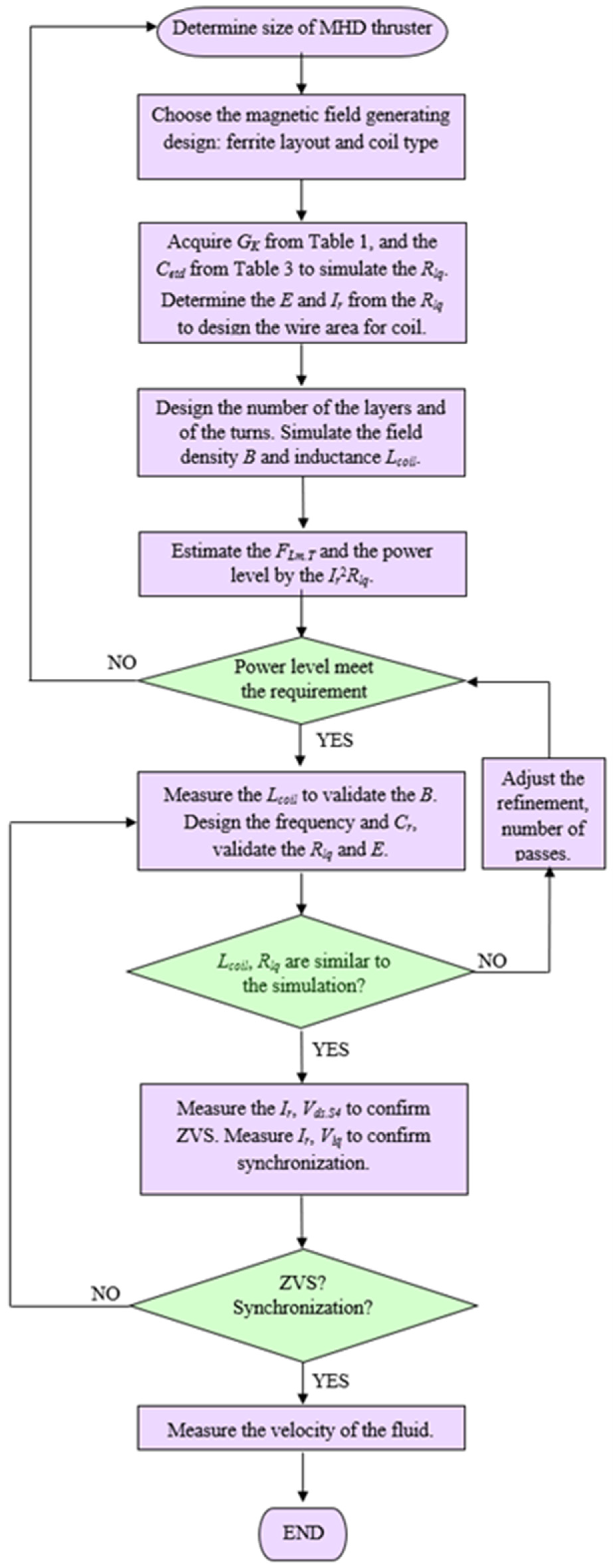
3. Magnetic Coil Structure and Study of Simulation

Generating an AC magnetic field within a duct’s liquid requires careful consideration of the coil design, weighing the trade-offs between weight, layout, and installation complexity. Figure 2 illustrates the conventional saddle-type coil design, consisting of a single layer, where the wire surrounds the duct and is stacked on the upper side to create the coil layer. To avoid obstructing the fluid duct, the wire at the fluid inlet and outlet sides must be rotated along the duct wall. High relative permeability ferrite can be positioned on the outer sides of the coil to decrease the total reluctance for high-frequency AC. The coil routes the wire on three walls of the duct, generating the magnetic field upwards or downwards. A flaw comes with the saddle-type coil: the multi-layer design will occupy considerable space on the upper side of duct wall where it connects the left and right, and wasting the room in the middle. Therefore, the coil design must be carefully optimized to achieve optimal performance.
A new coil layout for the MHD thruster is depicted in Figure 3, known as the “pancake coil winding”. This coil consists of two spiral windings that encircle the duct above and below, with the ferrite stack located on the outer side. A winding circles in one side of the duct and generates the individual magnetic field into the fluid. As such, this layout provides the feasibility of the topology variations of the windings’ connection, for parallel or series. Unlike the saddle-type coil, which is composed of a single winding, damage to any side of the duct disables the thruster, whereas the parallel connection remains a half propulsion capacity. Another spatial advantage of this coil layout is that even if a multi-layer structure is required, the winding on opposite sides can be linked by only one wire.
Ferrite is able to increase the B in the duct. However, it is heavy, bulky and fragile. In different circumstances, the practical limitations constrain the its use. The finite element method (FEM) is a computational approximation for magnetic field distribution estimation and is widely used in relevant research [2]. The method divides a complex geometry into smaller finite elements, each described by equations, and are combined to create a system of equations that are solved numerically to describe the behavior of the entire geometry. The simulations of the coil designs have been conducted in this paper to show the field profile and field data. Figure 4 demonstrates the dimensional parameters of the MHD thruster, in which the width of the ferrite of the long edge is denoted as a; the ferrite width of the short edge is b; c and d denote the corresponding length of the inner side of the fluid flowing duct; and the distance between the fluid and ferrites in the Acrylic frame is denoted as e. The coil is installed from the inner wall of the acrylic shell with the ferrite. The fluid flow volume c = 134 mm, d = 40 mm, and the length l is 354 mm.
A high frequency operation reduces the resistance of the solution, as shown in Table 3. this can lead to higher energy efficiency and therefore the operation of the AC MHD thruster at a high frequency with the Litz wire. The wire has a cross-sectional area of 12.25 mm2, and the winding of the saddle-type stacks is the same height as the acrylic frame. For pancake coils, the plane area being filled by the wires is preferred over the hollow layout, for a larger B value. Assume that the ferrite has a relative permeability of 3300 and the saturation value is 0.5 T. The B-H curve is considered to be linear. The nonlinear residual is set at 0.001, refinement is 30% and the minimum number of passes is three.
Table 4 shows the simulation results of two excitation currents, indicating the average magnetic field densities of the corresponding coil designs. The saddle type performs slightly better than the pancake coil when a is 0, but no more than 10% in three dimensions of b. But the situation reverses when a = 5, meaning that the ferrite starts to enclose the duct. The pancake coil has a 17% higher value in 21 A and 18% in 3 than the saddle coil. By comparing the results of nos. 3–5, the thin enclosed ferrite leads to the optimal layout in the ferrite weight and B value trade-off. The values of B generated by the saddle coil have no or little variance, but the mass of ferrite soar! The field distribution characteristics of the simulations are shown in Figure 5.

4. Electric Drive and Lorentz Force Analysis

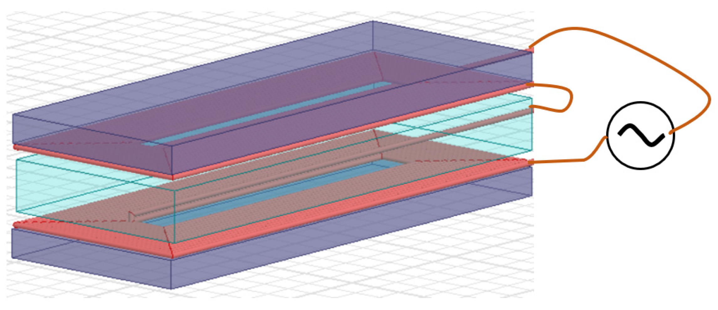
4.1. Electric MHD Thruster Drive Circuit

The series connection of the magnetic-field-generating coil and the fluid between the electrodes in the duct can ensure the in-phase operation of the electric and magnetic fields. A class-D half-bridge converter was proposed to build a high-frequency current for the MHD thruster, as shown in Figure 6. A full-bridge topology is able to inverse the DC input voltage Vin to the AC high-frequency current. The active switch affects set S1, S4, and set S2, S3 will be ON and OFF complementary to the 0.5 duty cycle at frequency fs to form the square waveform amplitude at Vin. The resonant capacitor Cr is deployed to resonate with the coil inductance Lc and the parasitic inductance Lp of the wire loop, and Rp denotes the loop resistance. The electric circuit model of fluid illustrated in Section 2 is framed by the dashed line marked as fluid, with an additional parallel resistor Rload for the fluid flow power consumption. Points C and D are the contact electrodes.
When S1, S4 are ON, the Vin applies to the circuit, and the resonant tank consists of Cr and Lc, while Lp conducts the current Ir to the sinusoidal waveform. After half of the cycle period, S1, S4 are OFF and S2, S3 will be ON. The resonant tank thereby discharges the energy stored in the reactance component and then circulates the current through the active switches in the reverse direction of Ir. Thus, the AC system is achieved. Therefore, the voltage applies to the resonant circuit VAB, according to the first harmonic approximation, can be Equation (1), where circuitry reactance angle is θ.
V A B = 4 V i n sin 2 π f s t + θ π
The impedance of the fluid ZCD can be acquired as Equation (3), where the angular resonant frequency ωs is defined in Equation (2), and the phase angle of the imaginary part is denoted as θ’.
ω S = 2 π f S = 1 L c C r
Z C D = ( 1 j ω s C e l d + 1 R l o a d + 1 R e l y t + 1 R e l y s ) 1
The current Ir can be acquired by Equation (4), although ZCD is not a constant, but rather changes with the power level. Practically, fs will be set to a value slightly higher than the resonant frequency to allow the inductive operation to reduce the switching energy. The first and second parts of the polynomial in the denominator will be a comparatively small component of ZCD.
I r = V A B Z A B = V A B j ω s L c + L p + 1 j ω s C r + R p + Z C D
And the circuit efficiency η of the MHD thruster could thus be derived as (5).
η = ( I r Z C D R l o a d cos θ ) 2 R l o a d I r V A B cos θ = ( Z C D cos θ ) 2 R l o a d Z A B cos θ

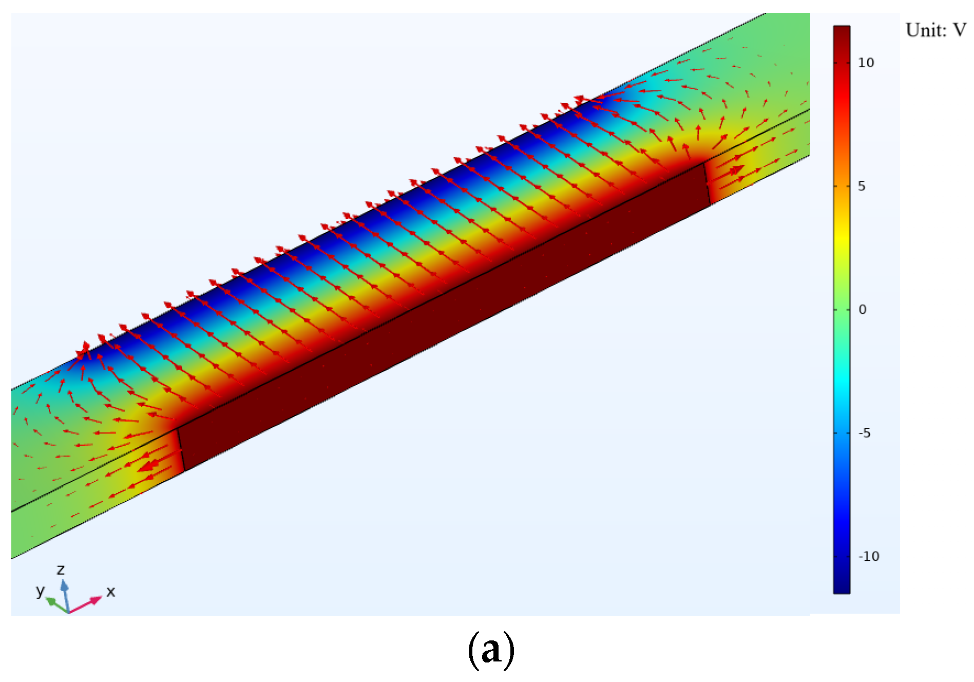
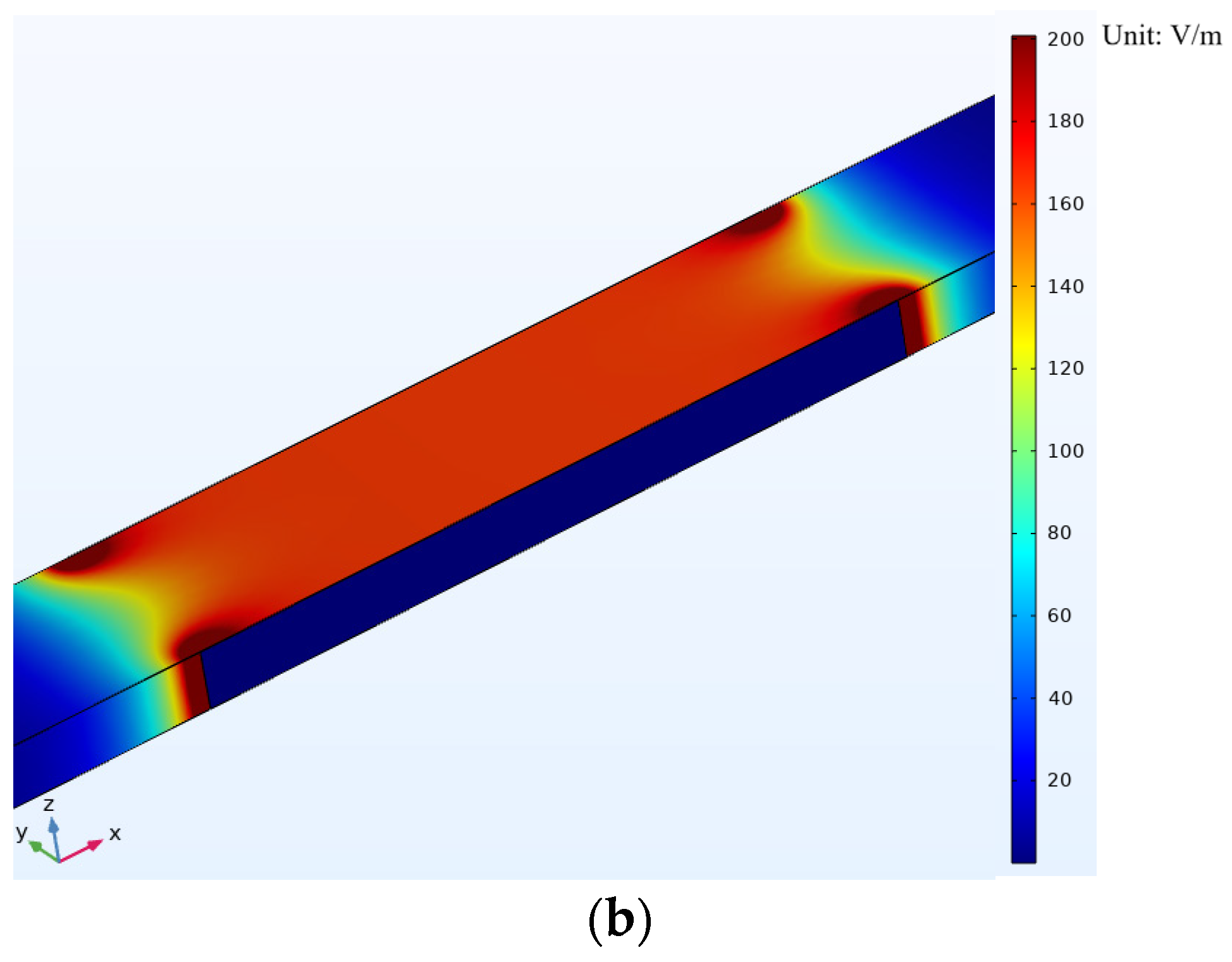
4.2. Electromagnetic Field in Duct of MHD Thruster and Lorentz Force Analysis

Figure 7 depicts the proposed AC MHD thruster, where the electrodes are fixed orthogonally to the magnetic-field-generating coil. As shown in Figure 8, the magnetic field direction will point either up or down. As shown in [35], the Lorentz force consists of the electric component FLe and the magnetic component FLm, which can be seen in Equation (6). The electric component is determined by the electron ion α that carries qα and the electric field density E, while that of that of the magnetic field is determined by the qα, the ion moving velocity along the E direction ve·α, and the cross product of B that leads to the fluid acceleration direction and is perpendicular to the electromagnetic field vector plane.
F L = F L e + F L m = q α E + q α v e · α × B
The electric field can be estimated by the VCD, as shown in Equation (7), in which c is the width of the duct, namely the distance of the electrode. And the B value can be acquired by the simulation.
E = V C D c
For the electron model [3], ve·α is related to the charged density ρα and the corresponding current density Jα (8). In the KCl laboratory testing fluid, we can assume Jα to be half the total current density J.
v e · α = J α ρ α = J 2 ρ α = I r 2 d l ρ α
Being accelerated in opposite directions along the E field line, the anion and cation together drift through the duct in the same direction due to the right-hand rule. The adverse charges and velocity vector enables the positively and negatively charged particles to be constantly pushed in a single direction regardless of whether instantaneous value of the electric current is positive or negative. Accordingly, in case of the laboratory seawater-level salinity solution and in view of the electric conductivity, all of the moving ions in the potassium chloride solution are K + and C l , resulting in the total Lorentz force in flow direction FLm·T, as is shown in Equation (9). Assume that the dissolved mass of particle α is mα and that the corresponding mole mass is Mα. Avogadro’s constant is denoted as NA.
F L m · T = α = 1 2 m α N A M α q α v e · α × B

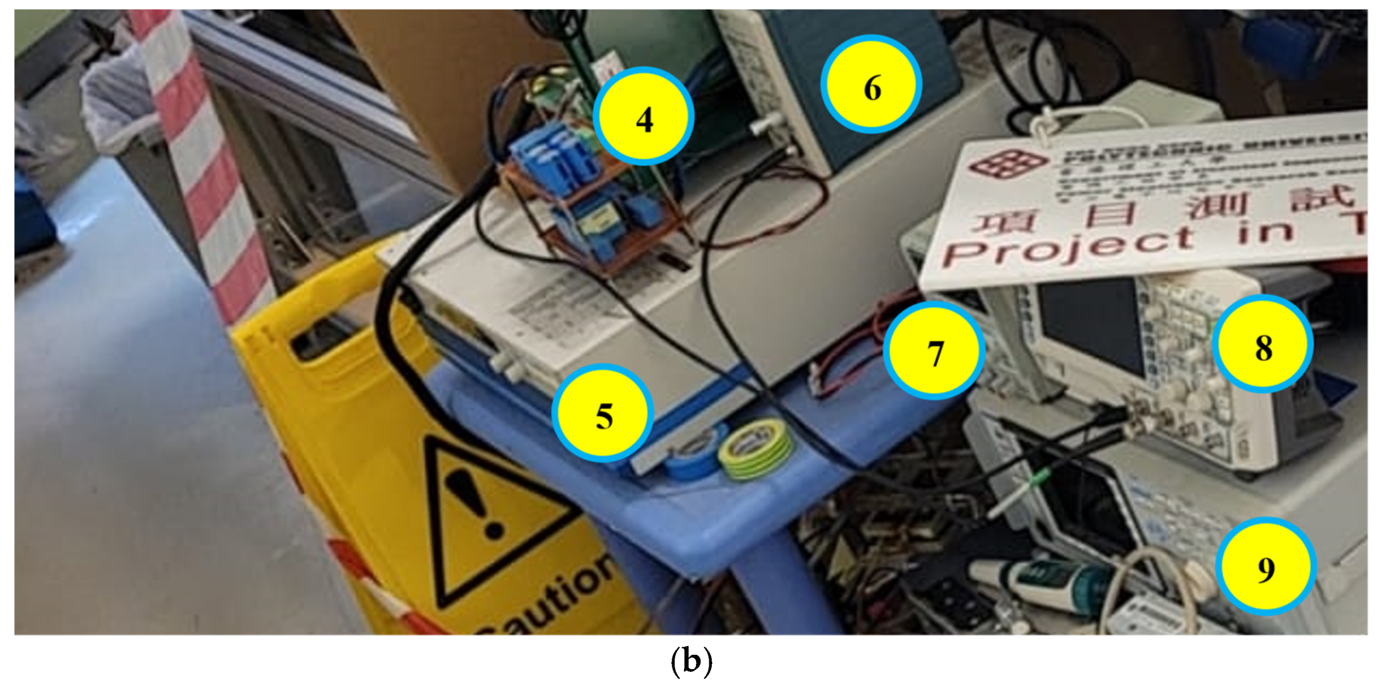
5. MHD Thruster Experimental Results

The experiment has been set in Figure 9. In the picture, 1 is the proposed AC MHD thruster, 2 is the water tank, 3 is the voltage probe, 4 is the proposed AC MHD thruster drive, 5 is the DC power supply for VDC, 6 is the amplifier of the current probe, 7 is the low voltage power supply for the gate-signal controller module, 8 is the oscilloscope, and 9 is the frequency response analyzer.
The length l of the duct is 550 mm, c is 133, d is 40 mm. The material of the electrode is aluminum. The coil is the same type as no. 1, a single layer on top and below the duct, with a 20 mm height ferrite block rated at 3300 relative permeability. The coil filled the space completely, from the edge to the center, and the ferrite block as well. The acrylic wall’s width is 10 mm, the gaps between the plates are sealed by sealant, and the opening up is covered by a transparent plastic film for waterproofing. The solution in the water tank is the standard salinity KCl solution, which has a weight fraction of S = 35.
Simulation results of the coil inductance are 317.58 μH, the average B value in the duct is 3.12 mT, as shown in Figure 10. The inductance of the Lc is measured by the item labeled as 9 in Figure 9b, which equals 330.93 μH, and Lp is 5.63 μH. The inductance simulation value is closed, and the B estimation thus can be trusted.
The testing solution’s temperature is 23 °C, and the simulated RCD, the resistance between the electrodes, using the S = 35 conventional seawater standard data is 1.26 Ω, but the measurement of the experimental liquid is 1.1 Ω. The conductivity ratio of the standard to the 10 kHz measurement value in Table 1 at 20 °C is 0.83, namely the 10 kHz resistance should be 0.83 times the estimation at 20 °C. The conductivity ratio is 1.1/1.26 = 0.87, with a 5% variance in the resistance estimation.
A simulation of the electric circuit drive was conducted. To circulate the 21 A current of Ir in the field-generating components, assume the RCD is 1.2 Ω. Apply the inductance of the coil from simulation 330 μH, and set the Lps as 6 μH. By setting the frequency of the drive circuit at 15 kHz, Cr is 340 nF, and the resonant frequency is 14.9 kHz, which is a bit slower than the switching frequency, and ZVS should be achieved. The simulation result are shown in Figure 11, in which VgsS3 and VgsS4 are the gate signal of the switch S3 and S4, respectively; and VdsS3 and VdsS4 are the drain source voltages of the MOSFET S3 and S4, respectively. When VgsS3 is high, VgsS4 is low, the switches of S3 is ON, the VAB is low, Ir is therefore negative, and when the switching time comes, it keeps the negative value to circulate through the body diode of S4, thus achieving the ZVS [36]. VAB is the alternating voltage from the DC power supply, where Vin = 40 V, Ir = 21 A and VCD = 24.5 V. The voltage drop of the resistance in the loop is 9.6 V.
For the validation experiment, Cr is 758 nF so as to resonate with Lp, and Lc is 9.96 kHz. The 10 kHz fs ensures the inductive operation of the drive circuit. Rp is 0.2 Ω. The power supply indicated the input current was 19 A when the VDC applied to the circuit was set at 30 V. As shown in Figure 12, when the drain-source voltage of the switch S4 Vds·S4 reaches zero, Ir is positive. The rms value of Ir is 22 A, and the voltage VCD between electrodes in the duct is 23 V and is synchronized, revealing the impact from Cetd can be neglected. Hence, the field of E and B have no phase angle.
The comparison between the experiment and simulation is displayed in Figure 13. The circuit parameters of Cr, Lcoil, Lps, Vin and fs are all the same. The RCD of the simulation is adopted with the measurement conductivity of the KCl solution 1.1 Ω. Ir is positive when the Vds·S4 is switched to low. Accordingly, the inductive operation and the following ZVS of the simulation and the experiment is achieved, with the synchronized B and E values derived from Ir and VCD, which implies the resonant frequency of the drive circuit and that the proposed drive method complies the electric analysis and the practical application. Ir in the experiment is higher than in the simulation. The reason comes from the parallel electrolysis and kinetic energy resistances in the real MHD engine, which decrease RCD and leads to the larger Ir.
The simulation result is depicted in Figure 14, in which the E field constructs the E field line, as shown in Figure 14a, and the simulation value within the electrode plates is 169 V/m, as shown in Figure 14b, which is 7.7% lower than the experimental result of 182 V/m.
Fluid flow was recorded by the ink, following method described in [19], and the reference points to measure the fluid velocity at the outlet of the duct was compared, as shown in Figure 15. The thruster is pushing the ink out from the outlet. The fluid velocity at the outlet is 3 cm/s.
A design flow chart in Figure 16 displays the development procedure of the MHD thruster.

6. Conclusions

This paper validates the concept of the AC MHD thruster and develops a prototype to demonstrate its very detailed parameters. Several tables about the frequency response of the KCl solution rated at seawater-level salinity from 10 kHz to 1.2 MHz are provided to fill the knowledge gap in this area. The measurement results indicate the fact that the conductivity of the solution rises with increasing frequency leads to lower power loss for the conduction loss advantages of the AC. The equivalent resistance model of the power consumption for the solution is interpreted by comparing 316 stainless steel, zinc and aluminum. Among them, aluminum is the optimal electrode material in the electrical aspect since it has the lowest parallel capacitance and resistance in the electrode–electrolyte interface. In addition, the simulation of magnetic field distribution and the field magnitude reveals that the pancake winding coil could generate a higher B field than the conventional saddle-type coil in an MHD thruster coil design to provide a higher power density for the MHD thruster. The AC electric drive circuit is presented and validated by the experiment.
The comprehensive analysis of the marine AC MHD thruster, covering thorough simulation, measurement, the experiment about the salinity–conductivity conversion, coil design, fluid equivalent circuit, thruster drive design, and real fluid pushing test, are interpreted.
This paper illustrates the operation principle, impacts of the frequency on the electrolyte and electrolysis regarding the various material, laboratory solution, drive circuit analysis in power electronics, experimental setup and design flowchart. The authors hope the comprehensive demonstration can invoke researchers’ interest in the maritime application of MHD thrusters.

Author Contributions

Conceptualization, K.L.J.K.; methodology, K.L.J.K. and K.W.E.C.; validation, K.L.J.K. and H.-C.Z.; formal analysis, K.L.J.K.; investigation, K.L.J.K. and H.-C.Z.; resources, K.W.E.C. writing—original draft preparation, K.L.J.K.; writing—review and editing, K.L.J.K. and K.W.E.C.; supervision, K.W.E.C.; project administration, K.W.E.C. All authors have read and agreed to the published version of the manuscript.

Funding

This research was funded partly by the University Grant Council RGF under grant PolyU 152218/19E and Green Power Research Study 845G.

Conflicts of Interest

The authors declare no conflict of interest.

References

  1. Schoeman, R.P.; Patterson-Abrolat, C.; Plön, S. A Global Review of Vessel Collisions With Marine Animals. Front. Mar. Sci. 2020, 7, 292. [Google Scholar] [CrossRef]
  2. Byard, R.W.; Machado, A.; Woolford, L.; Boardman, W. Symmetry: The key to diagnosing propeller strike injuries in sea mammals. Forensic Sci. Med. Pathol. 2013, 9, 103–105. [Google Scholar] [CrossRef] [PubMed]
  3. Byard, R.W.; Winskog, C.; Machado, A.; Boardman, W. The assessment of lethal propeller strike injuries in sea mammals. J. Forensic Leg. Med. 2012, 19, 158–161. [Google Scholar] [CrossRef] [PubMed]
  4. Joe, D.; Vijayakumar, R. Numerical study of acoustic characteristics of a marine propeller in non-uniform flow. In Global Oceans 2020: Singapore–USS; Gulf Coast: Biloxi, MS, USA, 2020. [Google Scholar]
  5. Aktas, B.; Atlar, M.; Leivadaros, S.; Sasaki, N.; Fitzsimmons, P. Hydropod: An Onboard Deployed Acoustic–Visual Device for Propeller Cavitation and Noise Investigations. IEEE J. Ocean. Eng. 2019, 44, 72–86. [Google Scholar] [CrossRef]
  6. National Marine Fisheries Service (NMFS). Technical Guidance for Assessing the Effects of Anthropogenic Sound on Marine Mammal Hearing: Underwater Acouustic Threshoulds for Onset of Permanent and Temporary Threshould Shifts; National Marine Fisheries Service (NMFS): Silver Spring, MD, USA, 2016. [Google Scholar]
  7. Way, S. Electromagnetic propulsion for cargo submarines. J. Hydronautics 1968, 2, 49–57. [Google Scholar] [CrossRef]
  8. Xue, X.D.; Cheng, K. A study of the status and future of superconducting magnetic energy storage in power systems. Supercond. Sci. Technol. 2006, 19, R31–R39. [Google Scholar] [CrossRef]
  9. Takezawa, S.; Tamama, H.; Sugawawa, K.; Sakai, H.; Matsuyama, C.; Morita, H.; Suzuki, H.; Ueyama, Y. Operation of the thruster for superconducting electromagnetohydrodynamic propulsion ship YAMATO-1. Bull. Mar. Eng. Soc. Jpn. 1995, 23, 46–55. [Google Scholar]
  10. Nandi, P. Effect of alternating current on electrolytic solutions. IOSR J. Eng. 2013, 3, 58–59. [Google Scholar] [CrossRef]
  11. Kundu, B.; Saha, S. Review and Analysis of Electro-Magnetohydrodynamic Flow and Heat Transport in Microchannels. Energies 2022, 15, 7017. [Google Scholar] [CrossRef]
  12. Abbas, M.A.; Ahmed, B.; Chen, L.; Rehman, S.U.; Saleem, M.; Khudair, W.S. Analysis of Entropy Generation on Magnetohydrodynamic Flow with Mixed Convection through Porous Media. Energies 2022, 15, 1206. [Google Scholar] [CrossRef]
  13. Haghparast, M.; Pahlavani, M.R.A. A Comparative Study on the Performance of Marine Magnetohydrodynamic Motors With Helical and Linear Channels. IEEE Trans. Magn. 2019, 55, 1–8. [Google Scholar] [CrossRef]
  14. UNESCO. UNESCO (1966): Table One in the National Oceanographic Tables; National Institute of Oceanography: Paris, France; Great Britain and UNESCO: London, UK, 1966. [Google Scholar]
  15. Lewis, E. The practical salinity scale 1978 and its antecedents. IEEE J. Ocean. Eng. 1980, 5, 3–8. [Google Scholar] [CrossRef]
  16. Alicki, R.; Gelbwaser-Klimovsky, D.; Jenkins, A. Leaking elastic capacitor as model for active matter. Phys. Rev. E 2021, 103, 052131. [Google Scholar] [CrossRef]
  17. Rahmawati, E.; Santoso, D.R.; Noor, J.A.F.; Nadhir, A. Electrical impedance analysis of NaCl and CaCl2 solutions based on equivalent electric circuit. J. Phys. Conf. Ser. 2022, 2165, 012025. [Google Scholar] [CrossRef]
  18. Lima, L.F.; Vieira, A.L.; Mukai, H.; Andrade, C.M.G.; Fernandes, P.R.G. Electric impedance of aqueous KCl and NaCl solutions: Salt concentration dependence on components of the equivalent electric circuit. J. Mol. Liq. 2017, 241, 530–539. [Google Scholar] [CrossRef]
  19. Haghparast, M.; Pahlavani, M.R.A.; Azizi, D. Fully 3-D Numerical Investi-gation of Phenomena Occurring in Marine Magnetohydrodynamic Thrusters. IEEE Trans. Plasma Sci. 2019, 47, 1818–1826. [Google Scholar] [CrossRef]
  20. Yoon, H.S.; Eum, Y.H.; Zhang, Y.; Shin, P.-S.; Koh, C.S. Comparison of Magnetic Reluctivity Models for FEA Considering Two-Dimensional Magnetic Properties. IEEE Trans. Magn. 2009, 45, 1202–1205. [Google Scholar] [CrossRef]
  21. Wang, D.; Yang, W.; Yang, J.; Jiang, K.; Fu, Y. Research on Electromagnetic Vibra-tion Characteristics of a Permanent Magnet Synchronous Motor Based on Mul-ti-Physical Field Coupling. Energies 2023, 16, 3916. [Google Scholar] [CrossRef]
  22. Cheng, K.W.E.; Evans, P. Calculation of winding losses in high-frequency toroidal inductors using multistrand conductors. IEE Proc.-Electr. Power Appl. 1995, 142, 312–322. [Google Scholar] [CrossRef]
  23. Lee, D.W.; Hong, B.G.; Kim, Y.; In, W.K.; Yoon, K.H. Preliminary design of a helium cooled molten lithium test blanket module for the ITER test in Korea. Fusion Eng. Des. 2007, 82, 381–388. [Google Scholar] [CrossRef]
  24. Lee, D.W.; Yoon, J.S.; Kim, S.H.; Kim, M.H.; Cho, S. MHD Analysis and Preparation of an Experiment for Developing the Korean Test Blanket Module. IEEE Trans. Plasma Sci. 2012, 40, 1472–1476. [Google Scholar] [CrossRef]
  25. Gregory, T.S.; Wu, K.J.; Yu, J.; Box, J.B.; Cheng, R.; Mao, L.; Tang, G.; Tse, Z.T.H. Magnetohydrodynamic-driven design of microscopic endocapsules in MRI. IEEE/ASME Trans. Mechatron. 2015, 20, 2691–2698. [Google Scholar] [CrossRef]
  26. Zeeshan, A.; Ijaz, N.; Abbas, T.; Ellahi, R. The sustainable characteristic of bio-bi-phase flow of peristaltic transport of MHD Jeffrey fluid in the human body. Sustainability 2018, 10, 2671. [Google Scholar] [CrossRef]
  27. West, J.; Karamata, B.; Lillis, B.; Gleeson, J.P.; Alderman, J.; Collins, J.K.; Lane, W.; Mathewsona, A.; Berneya, H. Application of magnetohydrodynamic actuation to continuous flow chemistry. Lab Chip 2002, 2, 224–230. [Google Scholar] [CrossRef] [PubMed]
  28. Bau, H.H. Applications of Magneto Electrochemistry and Magnetohydrodynamics in Microfluidics. Magnetochemistry 2022, 8, 140. [Google Scholar] [CrossRef]
  29. Lim, A.E.; Goh, S. Effect of Microchannel Diameter on Electroosmotic Flow Hysteresis. Energies 2023, 16, 2154. [Google Scholar] [CrossRef]
  30. Lim, A.E.; Lam, Y.C. Electroosmotic Flow Hysteresis for Fluids with Dissimilar pH and Ionic Species. Micromachines 2021, 12, 1031. [Google Scholar] [CrossRef]
  31. Cheng, K.W.E. Storage energy for classical switched mode power converters. IEE Proc.-Electr. Power Appl. 2003, 150, 439–446. [Google Scholar] [CrossRef]
  32. Lewis, E.L.; Perkin, R.G. The Practical Salinity Scale 1978 conversion of existing data. Deep-Sea Res. 1981, 28, 307–328. [Google Scholar] [CrossRef]
  33. Perkin, R.G.; Lewis, E.L. The Practical Salinity Scale 1978 Fitting the data. IEEE J. Ocean. Eng. 1980, 5, 9–16. [Google Scholar] [CrossRef]
  34. UNESCO. Tenth Report of the Joint Panel on Oceanographic Tables and Standards; United Nations Educational, Scienticfic and Cultural Organization: Paris, France, 1981. [Google Scholar]
  35. Garg, A.K. Classical Electromagnetism in a Nutshell, Princeton; Princeton University Press: Princeton, NJ, USA, 2012. [Google Scholar]
  36. Kan, K.L.J.; Cheng, K.W.E. Inductor-Aid Step-Up LLC Resonant Wireless Power Transfer. IEEE Access 2023, 11, 13370–13382. [Google Scholar] [CrossRef]
Figure 1. Resistance modelling of the electrolyte and electrolysis: (a) one of the testing rigs for the modelling of the conductive solution equivalent electric parameters; (b) the electrical circuit model of the conductive solution for MHD applications.
Energies 16 06021 g001
Figure 2. The conventional saddle-type coil of MHD thruster, with ferrite blocks beside to generate the magnetic field inside the duct for propulsion.
Energies 16 06021 g002
Figure 3. Pancake coil layout for MHD thruster, with ferrite blocks on the top and bottom to generate the magnetic field inside the duct for propulsion.
Energies 16 06021 g003
Figure 4. Dimensional parameters a, b, c, d, and e of the MHD thruster duct and coil: (a) pancake winding coil type; (b) saddle type.
Energies 16 06021 g004
Figure 5. The simulation study of the magnetic field generating coil designs and the field distribution characteristics: (a) no. 1, field magnitude; (b) no. 1, field direction; (c) no. 4, field magnitude; (d) no. 4, field direction; (e) no. 11, field magnitude; and (f) No. 8, field direction.
Energies 16 06021 g005
Figure 6. Proposed electric drive circuit for the AC MHD thruster the points A, B are the AC voltage injection port, whereas the points C, D are the voltage between the electrodes.
Energies 16 06021 g006
Figure 7. Picture of the proposed AC MHD thruster prototype being immersed in the KCl standard salinity solution for the experiment. The magnetic coil is a one-layer pancake winding type.
Energies 16 06021 g007
Figure 8. Coil installation of the prototype. Grey blocks are the ferrite, which are placed outside the tubes for the series connection of the electrodes, with the coil on top and below.
Energies 16 06021 g008
Figure 9. Experimental setup: (a) water tank and the immersed prototype with the link wire to the AC electric drive; (b) the electric experimental instrument and the AC MHD thruster drive.
Energies 16 06021 g009aEnergies 16 06021 g009b
Figure 10. Simulation of the magnetic field distribution in the duct and the ferrite by the FEM. (a) front view; (b) side view; (c) top view.
Energies 16 06021 g010aEnergies 16 06021 g010b
Figure 11. Simulation result of the 15 kHz drive circuit. RCD, Lcoil, and Lps are imported from the simulation of magnetic and electric field components. Both ZVS show as the lagging Ir of VAB, and the synchronization of Ir and VCD can be achieved.
Energies 16 06021 g011
Figure 12. Experimental result measurement waveform of the MHD thruster drive. CH1: VDC = 30 V; CH2: VCD, rms value is 23 V; CH3: Vds·S4; high-level is 30 V; low-level is 0 V; CH4: Ir, rms value is 22 A. The B and E are synchronized, and the ZVS is achieved.
Energies 16 06021 g012
Figure 13. The proposed drive circuit achieves the synchronization of the compound electromagnetic field as Ir and VCD that operates the MHD engine at the maximum efficiency of the fields. This indicates that comparing the simulation to the actual MHD engine prototype to identical drive circuit parameters of the electric drive conforms to the proposed electric drive circuit analysis. Ir shows 91% accuracy to the actual value.
Energies 16 06021 g013
Figure 14. Simulation result of the E field distribution in MHD duct. The parallel-plate volume is 7.7% lower than the experimental result: (a) the E field line distribution of the MHD thruster; (b) the E field result of the simulation.
Energies 16 06021 g014aEnergies 16 06021 g014b
Figure 15. The proposed AC MHD thruster is pushing out the fluid with the ink indicator.
Energies 16 06021 g015
Figure 16. Design flow chart of the marine AC MHD thruster.
Energies 16 06021 g016
Table 1. (a) The measurement conductivity GK of standard salinity KCl solution. (b) The measurement conductivity GNa of NaCl solution, with equivalent Cl mass concentration as the standard salinity KCl solution rated at S = 35. (c) The measurement conductivity GMg of MgCl2 solution, with equivalent Cl mass concentration as the standard salinity KCl solution rated at S = 35.
(a)
12.0 °C15.0 °C16.0 °C18.0 °C20.0 °C
10 kHz4.0244.2464.3374.6484.848
25 kHz4.0424.2754.3694.6974.879
64 kHz4.0774.3064.4004.7054.881
148 kHz4.1134.3484.4584.7824.964
300 kHz4.2294.4574.5844.8325.001
700 kHz4.6954.8904.9915.2545.435
1200 kHz5.7195.8785.9536.0826.258
mKCl‰ = 32.44‰, 0.0% higher than the standard salinity.
(b)
13.1 °C15.0 °C16.5 °C18.0 °C20.0 °C
10 kHz3.2753.4273.5503.6893.832
25 kHz3.2983.4493.5743.7113.856
64 kHz3.3213.4763.5963.7393.878
148 kHz3.3603.5123.6343.7743.916
300 kHz3.4843.6353.7543.8914.030
700 kHz4.0744.2124.3114.4214.548
1200 kHz5.3405.4285.4825.5485.666
mNaCl‰ = 25.41‰, 0.0% higher than the equivalent standard salinity.
(c)
15.0 °C16.0 °C17.0 °C18.0 °C20.0 °C
10 kHz4.5024.5824.6584.7514.945
25 kHz4.5374.6184.6954.7884.980
64 kHz4.5754.6584.7354.8285.019
148 kHz4.6184.7024.7794.8735.062
300 kHz4.7214.8034.8784.9735.156
700 kHz5.1775.2535.3185.4075.568
1200 kHz6.1236.1866.2366.3056.424
mMgCl2‰ = 39.93‰, +0.2% higher than the equivalent standard salinity.
Table 2. Equivalent salinity estimation of the KCl solution at the standard salinity solution fabrication of PSS-78 from the measurement conductivity at one atmospheric pressure, different temperatures and AC frequencies.
KCl12.0 °C15.0 °C16.0 °C18.0 °C20.0 °C
10 kHz35.7035.0434.9835.9735.93
25 kHz35.8835.3035.2736.3936.19
64 kHz36.2235.5935.5536.4636.20
148 kHz36.5835.9836.0737.1336.90
300 kHz37.7436.9937.2237.5737.21
700 kHz42.4441.0640.9441.2940.87
1200 kHz53.1150.6050.0448.7647.98
mKCl‰ = 32.44‰, 0.0% higher than the standard value.
Table 3. (a) The measurement results of the electrical equivalent series resistance and capacitance in MHD thruster duct, of which the electrodes are aluminum and at temperature at 20 °C. (b) The measurement results of the electrical equivalent series resistance and capacitance in MHD thruster duct, of which the electrodes are 316 stainless steel and at temperature of 18 °C. (c) The measurement results of the electrical equivalent series resistance and capacitance in MHD thruster duct, of which the electrodes are zinc and at a temperature of 20 °C.
(a)
Aluminumf (kHz)102564148300
0.35 V VetdCetd (μF)24.4919.8915.543.841.11
Relyt (Ω)2.132.132.041.941.93
5 V VetdCetd (μF)25.6714.819.952.340.78
Retd (Ω)2.022.051.991.991.96
Relys (Ω)35.6557.4980.8887.6592.52
7 V VetdCetd (μF)31.2117.219.953.070.67
Retd (Ω)2.102.011.972.132.03
Relys (Ω)142.5536.9057.2571.3283.38
(b)
316 stainless steelf (kHz)102564148300
0.35 V VetdCetd (μF)88.4287.2482.894.141.23
Relyt (Ω)2.462.392.302.222.19
5 V VetdCetd (μF)265.26127.3231.095.971.66
Retd (Ω)2.172.112.102.092.07
Relys (Ω)18.1728.6423.7734.6238.48
7 V VetdCetd (μF)397.89127.3241.456.331.83
Retd (Ω)2.052.022.022.022.11
Relys (Ω)12.19412.8516.4121.9959.41
(c)
Zincf (kHz)102564148300
0.35 V VetdCetd (μF)72.3470.7427.633.361.02
Relyt (Ω)3.403.333.223.143.06
5 V VetdCetd (μF)265.2690.9522.614.892.12
Retd (Ω)2.041.992.042.032.1
Relys (Ω)5.094.955.565.766.72
7 V VetdCetd (μF)265.26159.1512.438.961.71
Retd (Ω)1.951.951.961.922.08
Relys (Ω)4.574.715.004.956.52
Table 4. Simulation results of the coil designs with various ferrite layouts.
No.Layera (mm)b (mm)21 A, B (mT)30 A, B (mT)
Pancake coil110202.984.21
210102.894.13
31052.854.07
41554.526.46
515104.526.46
611054.526.46
720207.109.00
Saddle coil810203.244.63
910103.234.15
101053.224.11
111553.845.49
Disclaimer/Publisher’s Note: The statements, opinions and data contained in all publications are solely those of the individual author(s) and contributor(s) and not of MDPI and/or the editor(s). MDPI and/or the editor(s) disclaim responsibility for any injury to people or property resulting from any ideas, methods, instructions or products referred to in the content.

