


An Innovative H-Type Flux Switching Permanent Magnet Linear Generator for Thrust Force Enhancement


Abstract
:1. Introduction
1.1. Linear Electric Machines for Wave Energy
1.2. Requirements of Linear Power Take off in Wave Energy Converters
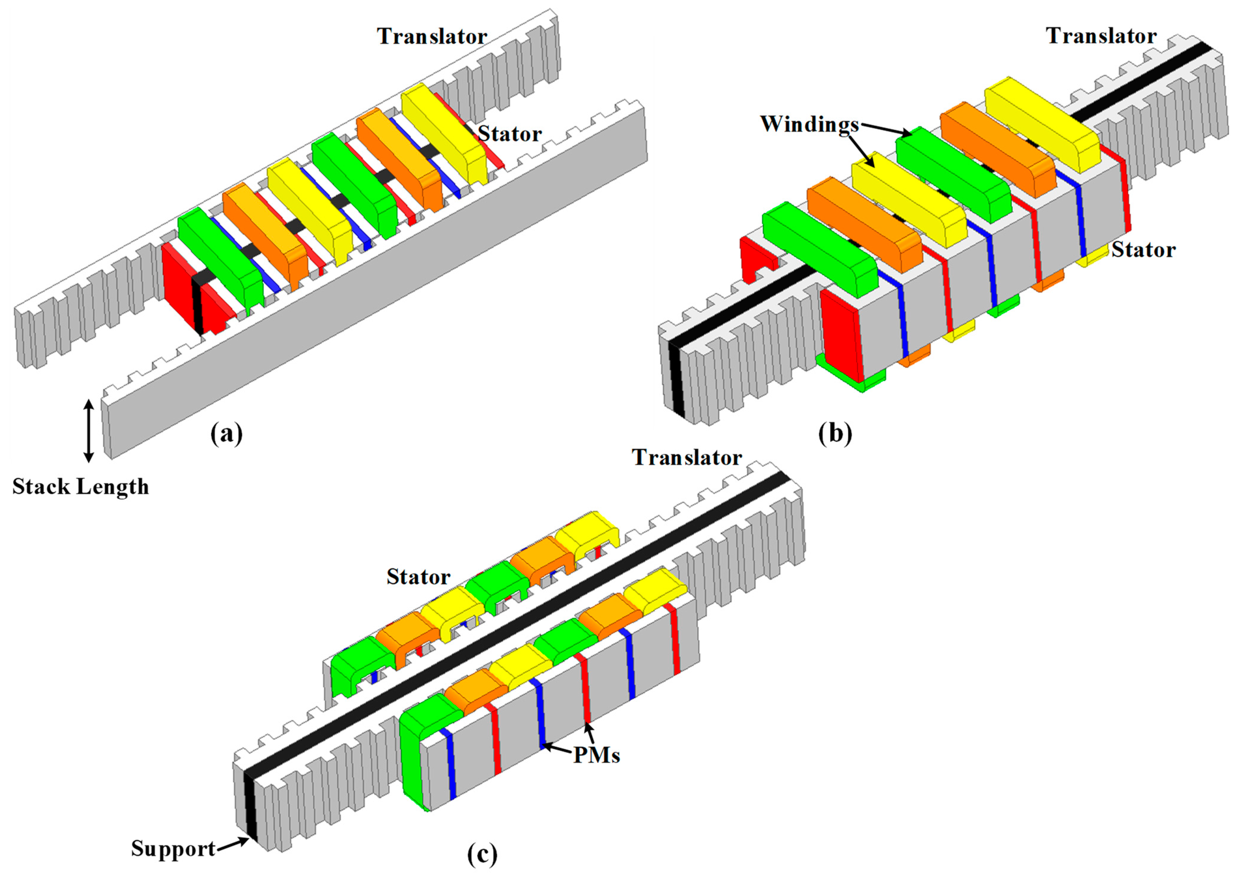
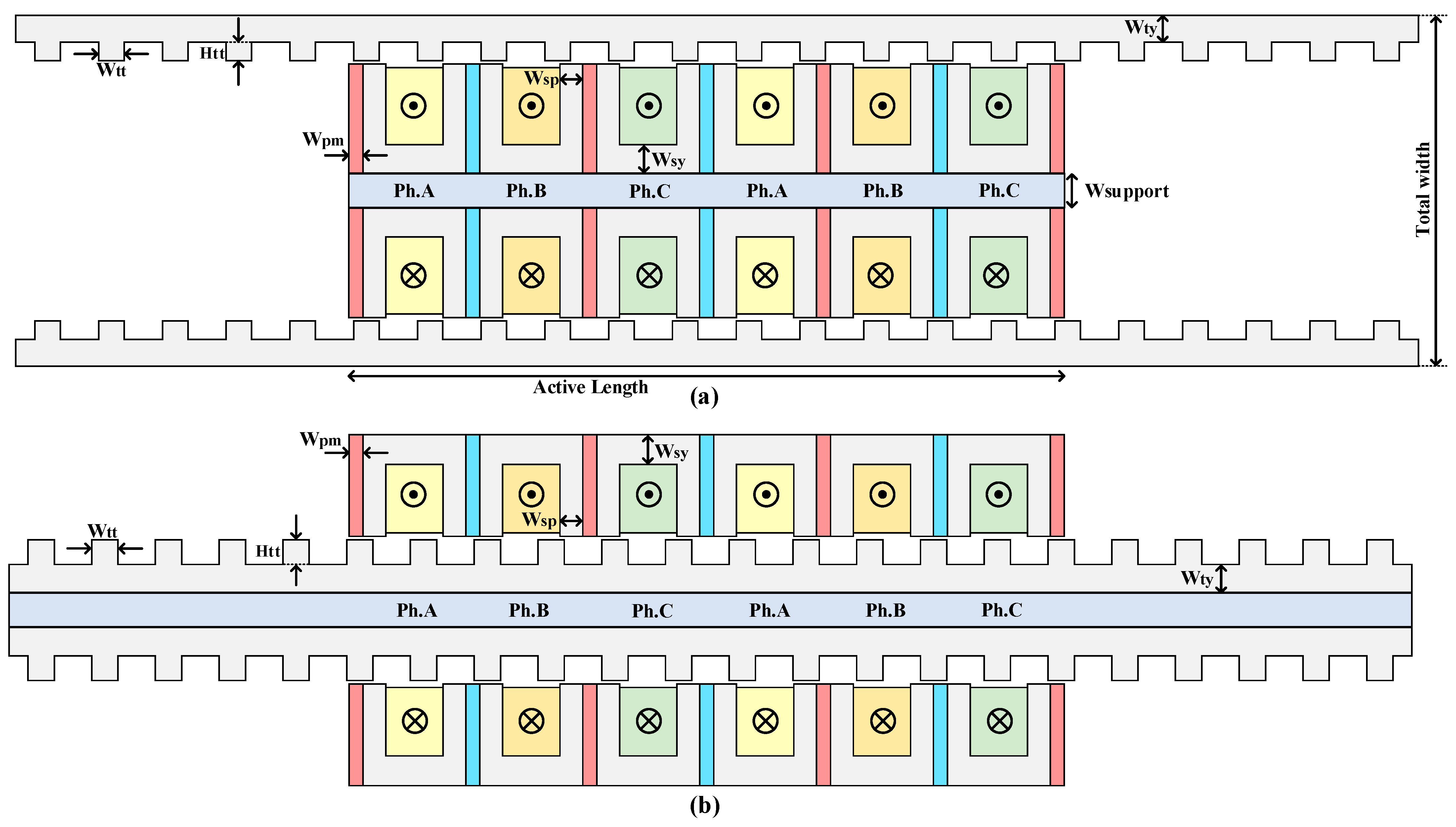
2. Machine Topology
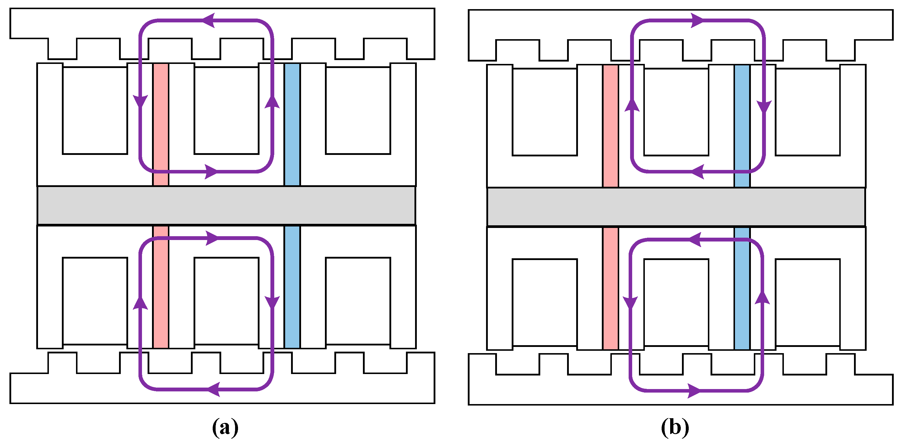
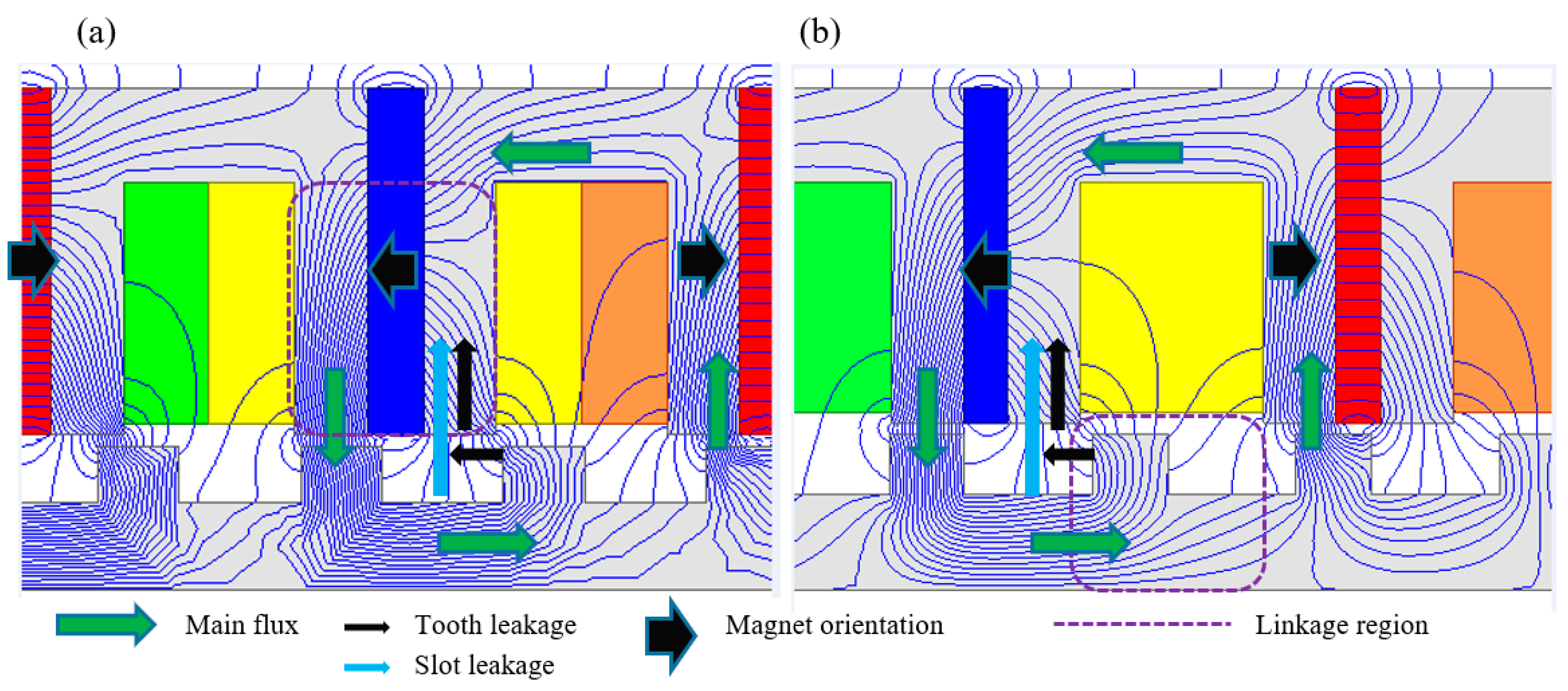
Operational Basics
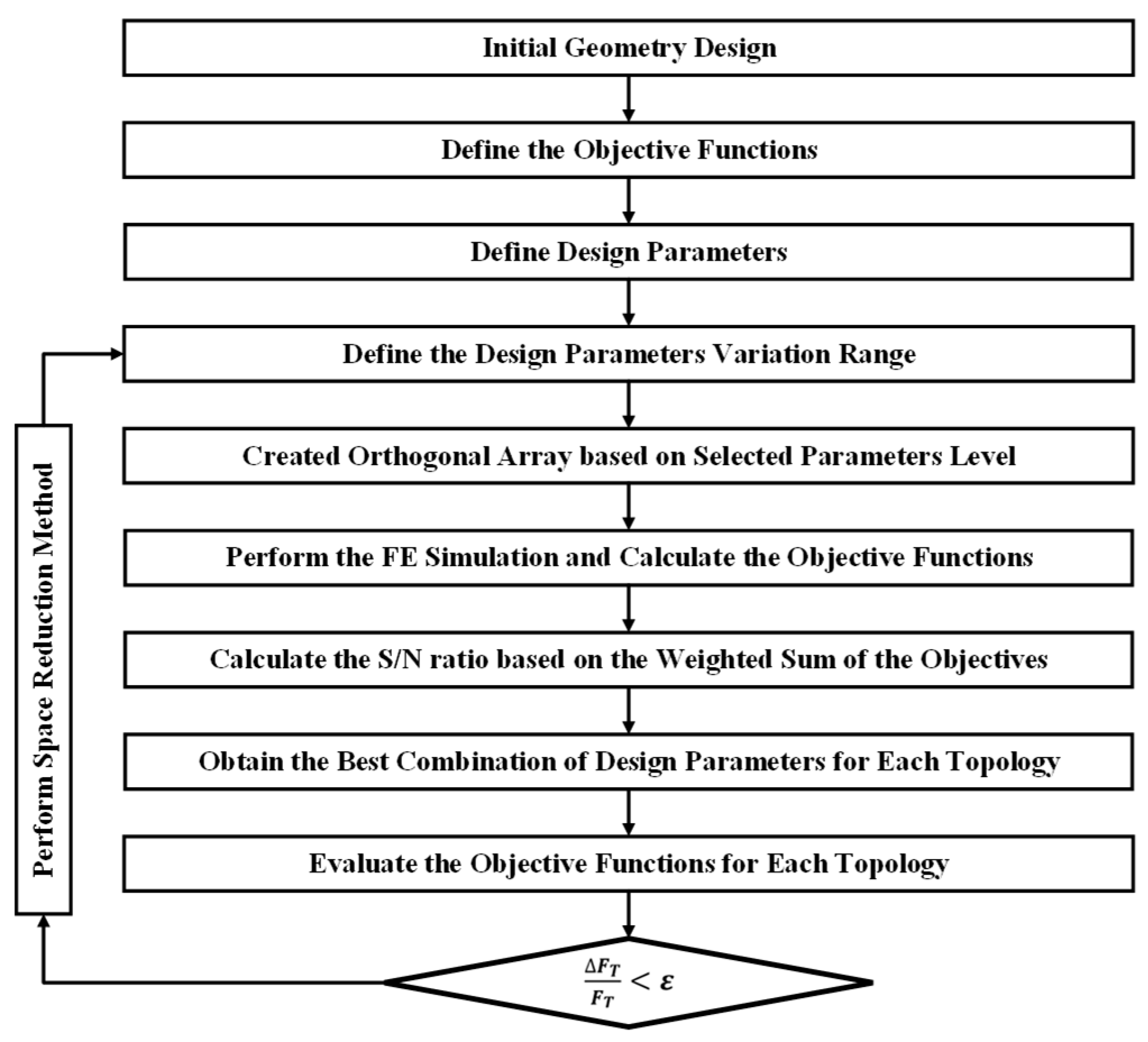
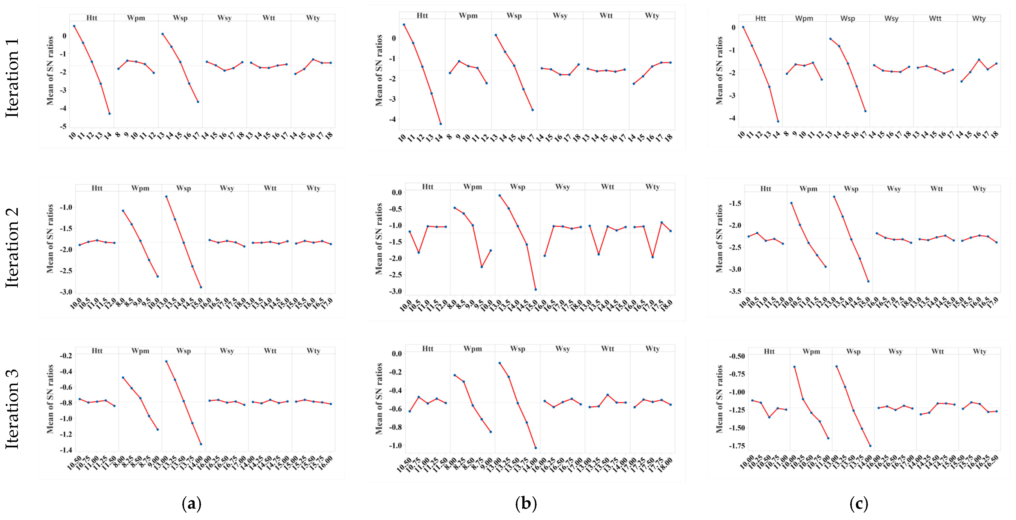
3. Design Optimization
3.1. Objective Function
3.2. Calculation of the S/N Ratio
3.3. Implementation of the Taguchi Method
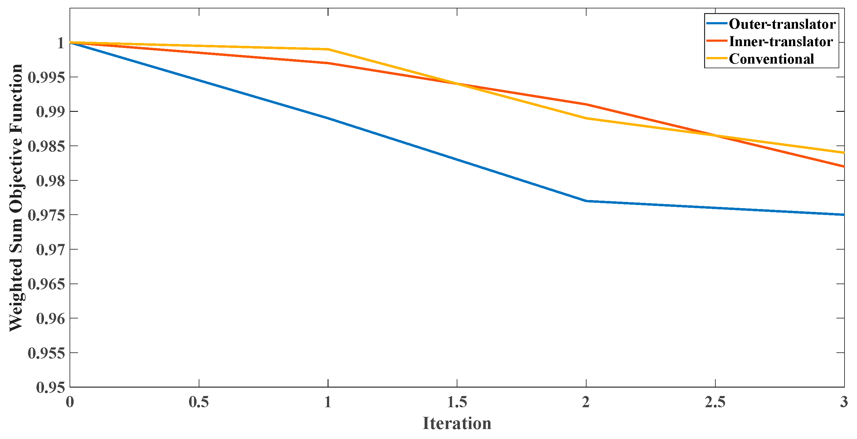
3.4. Space Reduction Method
3.5. Optimization Results
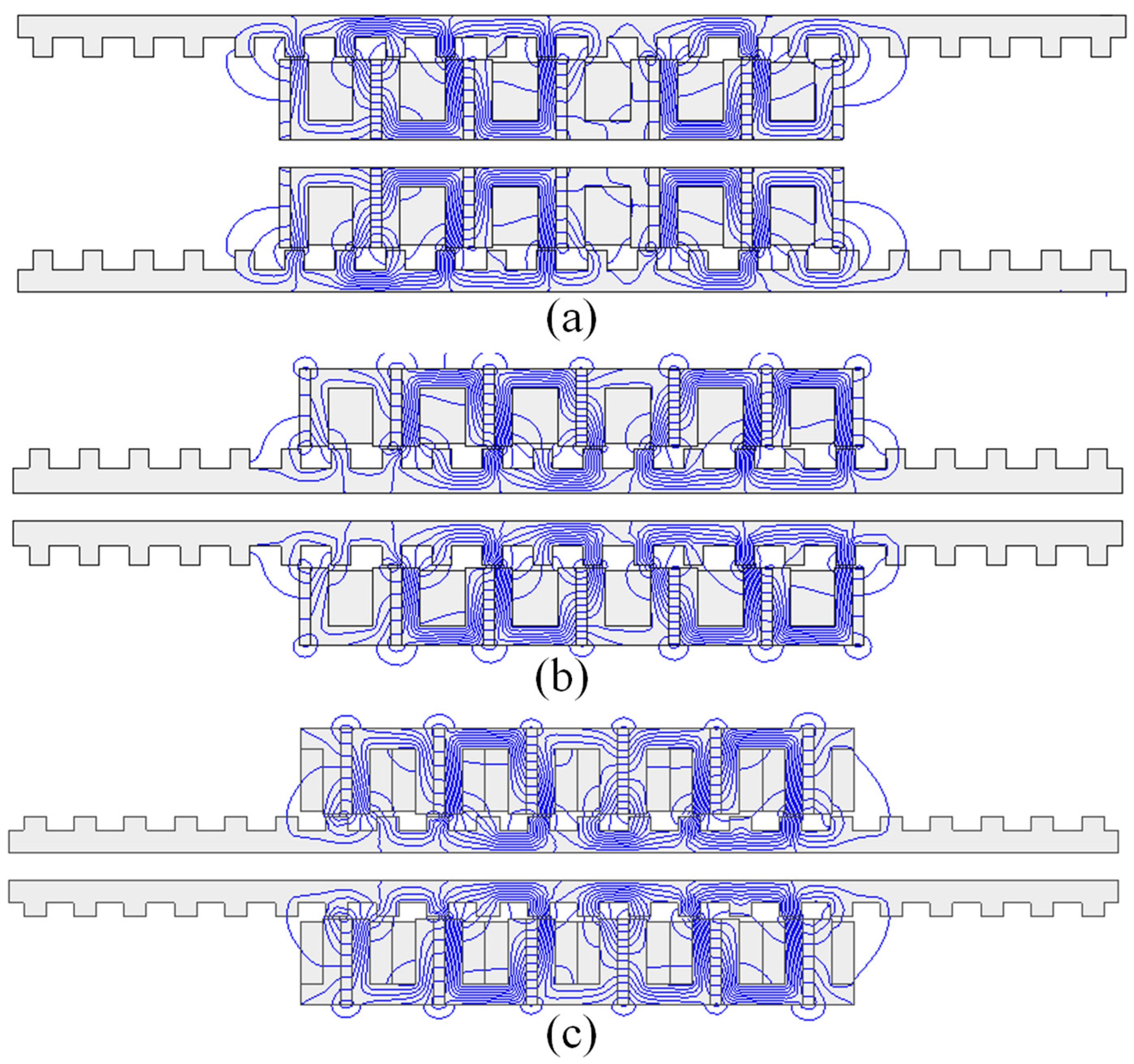
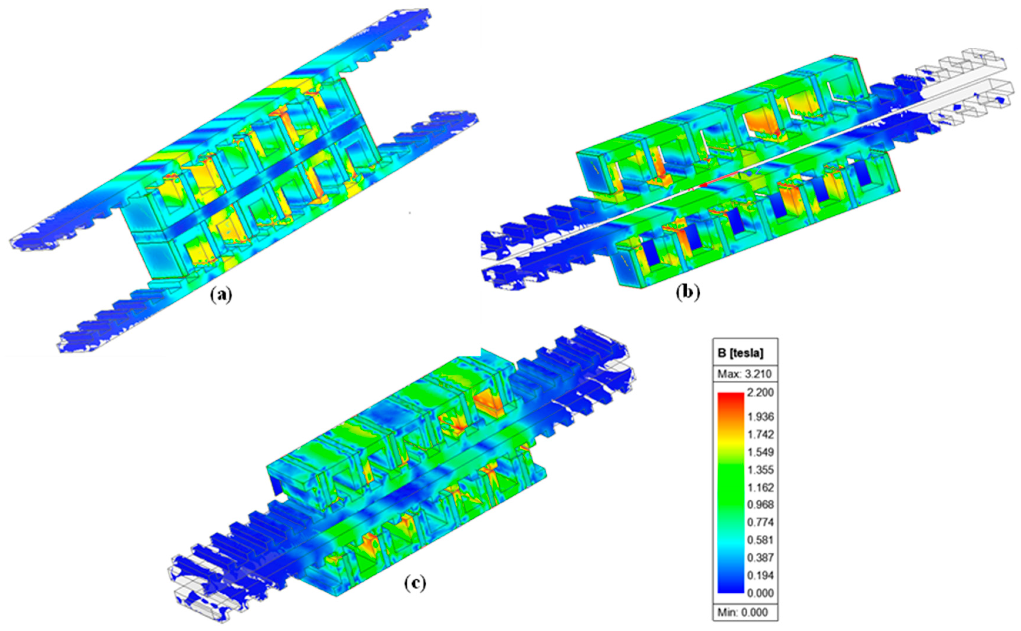
4. Simulation Results
5. Discussion of H Type Topology
5.1. Performance and Operation
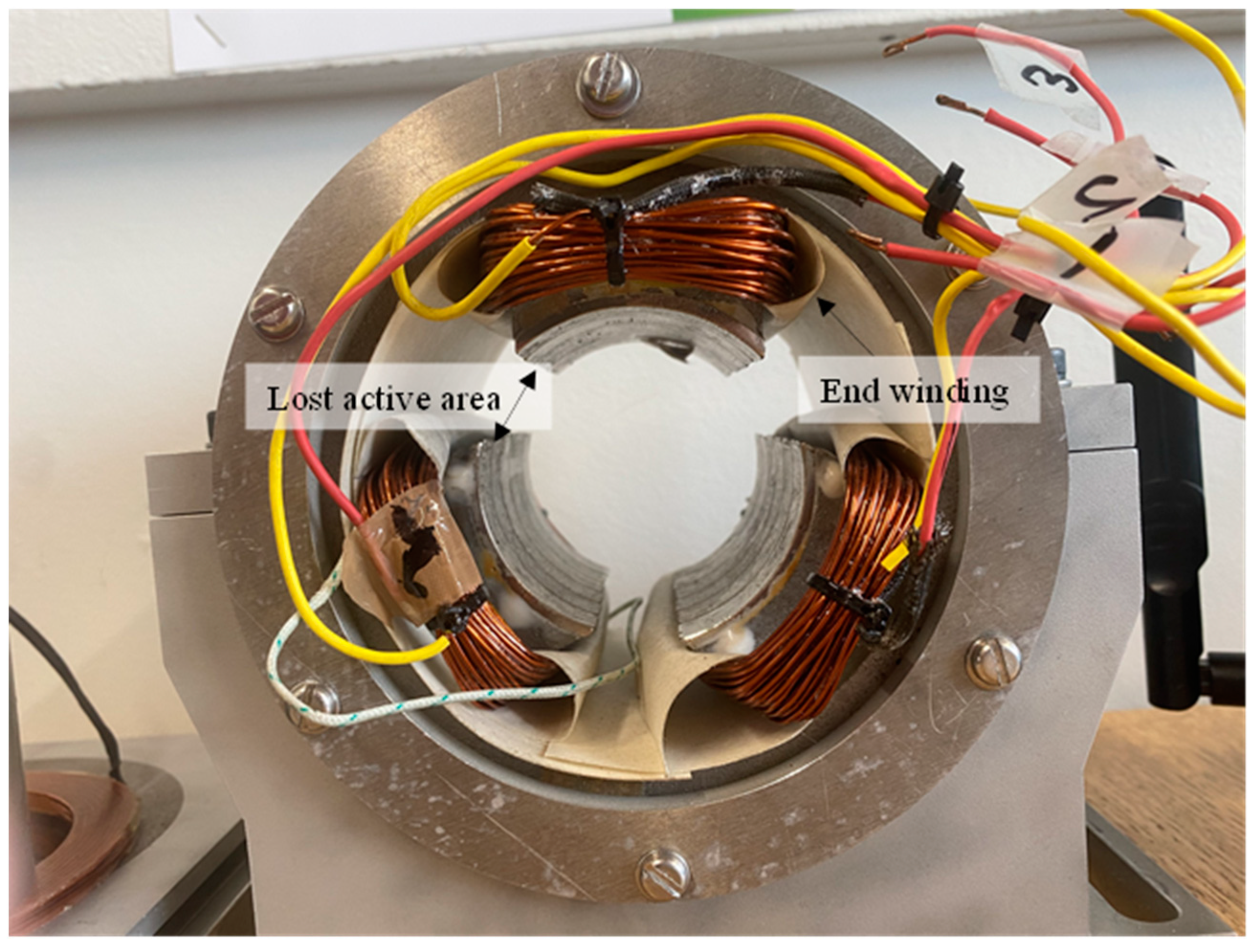
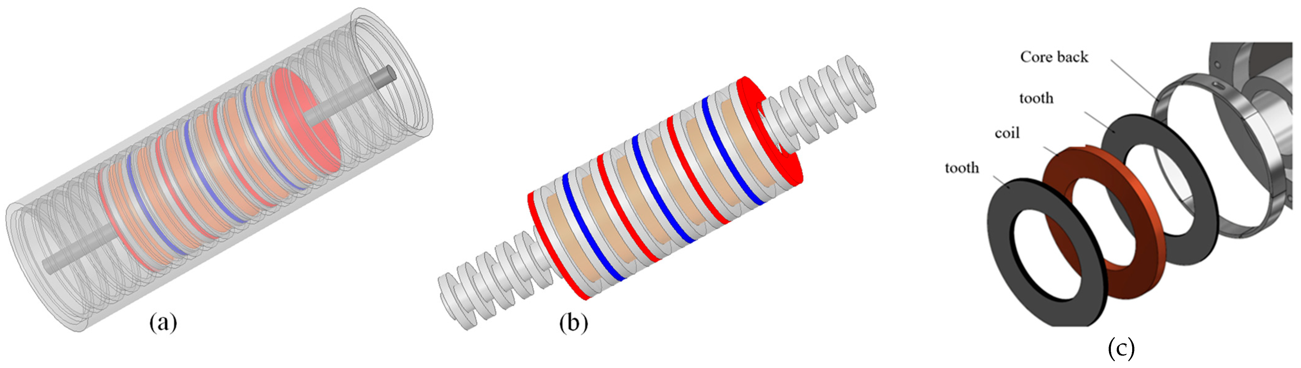
5.2. Cylindrical Variants and Manufacturing Issues
6. Conclusions
Author Contributions
Funding
Conflicts of Interest
References
- Farrok, O.; Islam, M.R.; Sheikh, M.R.I.; Guo, Y.; Zhu, J.G. A Split Translator Secondary Stator Permanent Magnet Linear Generator for Oceanic Wave Energy Conversion. IEEE Trans. Ind. Electron. 2018, 65, 7600–7608. [Google Scholar] [CrossRef]
- Rodriguez, L.G.-T.; Lafoz, M.; Torres, J.J.; Obradors, D.; Blanco, M.; Najera, J.; Navarro, G.; Garcia, F.; Sanchez, A. New Type of Linear Switched Reluctance Generator for Wave Energy Applications. IEEE Trans. Appl. Supercond. 2020, 30, 1–5. [Google Scholar] [CrossRef]
- Jing, L.; Wang, T.; Tang, W.; Liu, W.; Qu, R. Characteristic Analysis of the Magnetic Variable Speed Diesel–Electric Hybrid Motor with Auxiliary Teeth for Ship Propulsion. IEEE/ASME Trans. Mechatron. 2023. [Google Scholar] [CrossRef]
- Jing, L.; Liu, W.; Tang, W.; Qu, R. Design and Optimization of Coaxial Magnetic Gear with Double-Layer PMs and Spoke Structure for Tidal Power Generation. IEEE/ASME Trans. Mechatron. 2023. [Google Scholar] [CrossRef]
- Baker, N.J.; Almoraya, A.; Raihan, M.A.H.; McDonald, S.; McNabb, L. Development and Wave Tank Demonstration of a Fully Controlled Permanent Magnet Drive for a Heaving Wave Energy Converter. Energies 2022, 15, 4811. [Google Scholar] [CrossRef]
- Baker, N.J.; Raihan, M.A.H.; Almoraya, A.A. A Cylindrical Linear Permanent Magnet Vernier Hybrid Machine for Wave Energy. IEEE Trans. Energy Convers. 2019, 34, 691–700. [Google Scholar] [CrossRef] [Green Version]
- Almoraya, A.A.; Baker, N.J.; Smith, K.J.; Raihan, M.A.H. Design and Analysis of a Flux-Concentrated Linear Vernier Hybrid Machine with Consequent Poles. IEEE Trans. Ind. Appl. 2019, 55, 4595–4604. [Google Scholar] [CrossRef] [Green Version]
- Ching, T.W.; Chau, K.T.; Li, W. Power Factor Improvement of a Linear Vernier Permanent-Magnet Machine Using Auxiliary DC Field Excitation. IEEE Trans. Magn. 2016, 52, 1–4. [Google Scholar] [CrossRef]
- Xu, D.; Zhao, W.; Cheng, Y.; Chen, Q.; Xu, L. Power factor improvement of permanentmagnet linear vernier motor by using dualinverter with hybrid discontinuous PWM. IET Power Electron. 2019, 12, 3438–3446. [Google Scholar] [CrossRef]
- Qiu, S.; Zhao, W.; Zhang, C.; Shek, J.K.H.; Wang, H. A Novel Structure of Tubular Staggered Transverse-Flux Permanent-Magnet Linear Generator for Wave Energy Conversion. IEEE Trans. Energy Convers. 2022, 37, 24–35. [Google Scholar] [CrossRef]
- Chen, M.; Huang, L.; Hu, M.; Hu, B.; Ahmad, G. A Spiral Translator Permanent Magnet Transverse Flux Linear Generator Used in Direct-Drive Wave Energy Converter. IEEE Trans. Magn. 2021, 57, 1–5. [Google Scholar] [CrossRef]
- Vatani, M.; Ghaffarpour, A.; Kondelaji, M.A.J.; Mirsalim, M. Study of a Modular Toothed Linear Hybrid Reluctance Motor with Permanent Magnets in Translator Slots. IEEE Trans. Transp. Electrif. 2022, 8, 3554–3567. [Google Scholar] [CrossRef]
- Kondelaji, M.A.J.; Farahani, E.F.; Mirsalim, M. Teethed-Pole Switched Reluctance Motors Assisted with Permanent Magnets: Analysis and Evaluation. IEEE Trans. Energy Convers. 2021, 36, 2131–2140. [Google Scholar] [CrossRef]
- Radmanesh, H.; Farahani, E.F. Performance evaluation of a new modular split-tooth permanent magnet-assisted switched reluctance motor. IET Electr. Power Appl. 2022, 17, 441–451. [Google Scholar] [CrossRef]
- Farahani, E.F.; Mirsalim, M. Comprehensive study on divided-teeth and permanent magnet assisted outer-rotor switched reluctance motors. IET Electr. Power Appl. 2020, 14, 2293–2300. [Google Scholar] [CrossRef]
- Farahani, E.F.; Kondelaji, M.A.J.; Mirsalim, M. Divided Teeth Switched Reluctance Motor with Different Tooth Combinations. In Proceedings of the 2020 11th Power Electronics, Drive Systems, and Technologies Conference, PEDSTC 2020, Tehran, Iran, 4–6 February 2020. [Google Scholar] [CrossRef]
- Yan, L.; Li, W.; Jiao, Z.; Hu, H.; Chen, C.Y.; Chen, I.M. Design and modeling of tubular flux-switching permanent magnet linear motor. In Proceedings of the 2014 IEEE Chinese Guidance, Navigation and Control Conference, CGNCC 2014, Yantai, China, 8–10 August 2014; pp. 2799–2804. [Google Scholar] [CrossRef]
- Huang, L.; Yu, H.; Hu, M.; Zhao, J.; Cheng, Z. A novel flux-switching permanent-magnet linear generator for wave energy extraction application. IEEE Trans. Magn. 2011, 47, 1034–1037. [Google Scholar] [CrossRef]
- Huang, L.; Hu, M.; Liu, J.; Yu, H.; Zeng, C.; Chen, Z. Electromagnetic Design of a 10-kW-Class Flux-Switching Linear Superconducting Hybrid Excitation Generator for Wave Energy Conversion. IEEE Trans. Appl. Supercond. 2017, 27, 1–6. [Google Scholar] [CrossRef]
- Seo, S.W.; Jang, G.H.; Kim, J.M.; Choi, J.Y. Characteristic Analysis and Experimental Verification for a Double-Sided Permanent Magnet Linear Synchronous Generator According to Magnetization Array. IEEE Trans. Appl. Supercond. 2018, 28, 1–4. [Google Scholar] [CrossRef]
- Huang, L.; Liu, J.; Yu, H.; Qu, R.; Chen, H.; Fang, H. Winding configuration and performance investigations of a tubular superconducting flux-switching linear generator. IEEE Trans. Appl. Supercond. 2014, 25, 1–5. [Google Scholar] [CrossRef]
- Cai, J.; Lu, Q.; Huang, X.; Ye, Y.; Fang, Y. Performance investigation of a novel multi-tooth switched-flux linear motor. In Proceedings of the 2015 10th International Conference on Ecological Vehicles and Renewable Energies, EVER 2015, Monte-Carlo, Monaco, 31 March–2 April 2015. [Google Scholar] [CrossRef]
- Polinder, H.; Damen, M.E.C.; Gardner, F. Linear PM generator system for wave energy conversion in the AWS. IEEE Trans. Energy Convers. 2004, 19, 583–589. [Google Scholar] [CrossRef] [Green Version]
- Prudell, J.; Stoddard, M.; Amon, E.; Brekken, T.K.A.; Von Jouanne, A. A permanent-magnet tubular linear generator for ocean wave energy conversion. IEEE Trans. Ind. Appl. 2010, 46, 2392–2400. [Google Scholar] [CrossRef]
- Burchell, J.; Ahmed, N.; Barajas-Solano, J.I.; Mueller, M.; Galbraith, M. Project Neptune: Critical Component Tests for a Fully Flooded Direct-Drive Linear Generator for Wave Energy Convertors. In Proceedings of the 4th Asian Wave and Tidal Energy Conference, Taipei, Taiwan, 13 September 2018. [Google Scholar]
- Mahmouditabar, F.; Vahedi, A.; Takorabet, N. Demagnetisation optimisation of ring winding axial flux permanent magnet motor by modifying the load line of the magnet. IET Electr. Power Appl. 2023, 17, 928–938. [Google Scholar] [CrossRef]
- Mahmouditabar, F.; Vahedi, A.; Takorabet, N. Robust Design of BLDC Motor Considering Driving Cycle. IEEE Trans. Transp. Electrif. 2023. [Google Scholar] [CrossRef]
- Mahmouditabar, F.; Vahedi, A.; Takorabet, N. Design and Analysis of Interior Permanent Magnet Motor for Electric Vehicle Application Considering Irreversible Demagnetization. IEEE Trans. Ind. Appl. 2022, 58, 284–293. [Google Scholar] [CrossRef]
- Asanuma, J.; Doi, S.; Igarashi, H. Transfer Learning through Deep Learning: Application to Topology Optimization of Electric Motor. IEEE Trans. Magn. 2020, 56, 1–4. [Google Scholar] [CrossRef]
- Mahmouditabar, F.; Vahedi, A.; Mosavi, M.R.; Bafghi, M.H.B. Sensitivity analysis and multiobjective design optimization of flux switching permanent magnet motor using MLP-ANN modeling and NSGA-II algorithm. Int. Trans. Electr. Energy Syst. 2020, 30, e12511. [Google Scholar] [CrossRef]
- Korbekandi, R.M.; Baker, N.J.; Kulan, M.C.; Jalal, A.S.; Wu, D.; Li, M. Dynamic Characteristics and Demonstration of an Integrated Linear Engine Generator with Alternative Electrical Machines. Energies 2022, 15, 5295. [Google Scholar] [CrossRef]


| Parameter (Unit) | Symbol | Value |
|---|---|---|
| Active length (mm) | 400 | |
| Total width (mm) | 200 | |
| Stack length (mm) | 100 | |
| Air-gap length (mm) | 2 | |
| Support width (mm) | 20 | |
| Current density (A/mm2) | 6 | |
| Translator velocity (m/s) | 1 |
| Parameter | Level 1 | Level 2 | Level 3 | Level 4 | Level 5 |
|---|---|---|---|---|---|
| 10 | 11 | 12 | 13 | 14 | |
| 8 | 9 | 10 | 11 | 12 | |
| 13 | 14 | 15 | 16 | 17 | |
| 14 | 15 | 16 | 17 | 18 | |
| 13 | 14 | 15 | 16 | 17 | |
| 14 | 15 | 16 | 17 | 18 |
| Run | |||||||||||||||
|---|---|---|---|---|---|---|---|---|---|---|---|---|---|---|---|
| 1 | 11 | 11 | 15 | 18 | 15 | 30 | 0.793 | 1.004 | 0.989 | 0.814 | 0.956 | 0.997 | 0.906 | 1.052 | 1.010 |
| 2 | 11 | 12 | 16 | 19 | 16 | 31 | 0.835 | 1.108 | 1.031 | 0.819 | 1.014 | 1.020 | 0.871 | 1.181 | 1.082 |
| 3 | 11 | 13 | 17 | 20 | 17 | 32 | 0.902 | 1.232 | 1.080 | 0.884 | 1.136 | 1.067 | 0.919 | 1.303 | 1.141 |
| 4 | 11 | 14 | 18 | 21 | 18 | 33 | 1.043 | 1.391 | 1.150 | 1.006 | 1.269 | 1.116 | 1.092 | 1.411 | 1.199 |
| 5 | 11 | 15 | 19 | 22 | 19 | 34 | 1.183 | 1.559 | 1.216 | 1.151 | 1.419 | 1.185 | 1.253 | 1.603 | 1.273 |
| 6 | 12 | 11 | 16 | 20 | 18 | 34 | 0.960 | 1.066 | 1.030 | 0.928 | 1.001 | 0.989 | 1.002 | 1.111 | 1.036 |
| 7 | 12 | 12 | 17 | 21 | 19 | 30 | 1.053 | 1.173 | 1.071 | 1.047 | 1.068 | 1.030 | 1.125 | 1.259 | 1.124 |
| 8 | 12 | 13 | 18 | 22 | 15 | 31 | 1.123 | 1.320 | 1.126 | 1.109 | 1.172 | 1.090 | 1.170 | 1.383 | 1.194 |
| 9 | 12 | 14 | 19 | 18 | 16 | 32 | 1.239 | 1.453 | 1.190 | 1.236 | 2.158 | 1.143 | 1.206 | 1.476 | 1.244 |
| 10 | 12 | 15 | 15 | 19 | 17 | 33 | 0.891 | 1.188 | 1.070 | 0.863 | 1.062 | 1.034 | 0.999 | 1.227 | 1.120 |
| 11 | 13 | 11 | 17 | 22 | 16 | 33 | 1.147 | 1.136 | 1.062 | 1.082 | 1.027 | 1.032 | 1.171 | 1.209 | 1.117 |
| 12 | 13 | 12 | 18 | 18 | 17 | 34 | 1.248 | 1.242 | 1.105 | 1.178 | 1.155 | 1.053 | 1.229 | 1.324 | 1.191 |
| 13 | 13 | 13 | 19 | 19 | 18 | 30 | 1.525 | 1.390 | 1.156 | 1.556 | 1.271 | 1.143 | 1.612 | 1.478 | 1.244 |
| 14 | 13 | 14 | 15 | 20 | 19 | 31 | 0.999 | 1.123 | 1.050 | 1.003 | 1.044 | 1.029 | 1.034 | 1.234 | 1.107 |
| 15 | 13 | 15 | 16 | 21 | 15 | 32 | 1.051 | 1.267 | 1.102 | 1.132 | 1.151 | 1.068 | 1.089 | 1.327 | 1.189 |
| 16 | 14 | 11 | 18 | 19 | 19 | 32 | 1.478 | 1.205 | 1.083 | 1.498 | 1.122 | 1.053 | 1.454 | 1.247 | 1.101 |
| 17 | 14 | 12 | 19 | 20 | 15 | 33 | 1.651 | 1.318 | 1.141 | 1.584 | 1.184 | 1.092 | 1.642 | 1.407 | 1.234 |
| 18 | 14 | 13 | 15 | 21 | 16 | 34 | 1.095 | 1.090 | 1.029 | 1.079 | 1.018 | 1.012 | 1.103 | 1.202 | 1.098 |
| 19 | 14 | 14 | 16 | 22 | 17 | 30 | 1.249 | 1.231 | 1.081 | 1.271 | 1.097 | 1.044 | 1.225 | 1.304 | 1.135 |
| 20 | 14 | 15 | 17 | 18 | 18 | 31 | 1.384 | 1.345 | 1.133 | 1.480 | 1.232 | 1.091 | 1.406 | 1.375 | 1.197 |
| 21 | 15 | 11 | 19 | 21 | 17 | 31 | 2.224 | 1.273 | 1.123 | 2.198 | 1.188 | 1.068 | 2.101 | 1.342 | 1.128 |
| 22 | 15 | 12 | 15 | 22 | 18 | 32 | 1.223 | 1.054 | 1.023 | 1.207 | 0.979 | 0.987 | 1.295 | 1.137 | 1.053 |
| 23 | 15 | 13 | 16 | 18 | 19 | 33 | 1.351 | 1.140 | 1.059 | 1.349 | 1.033 | 1.028 | 1.386 | 1.244 | 1.128 |
| 24 | 15 | 14 | 17 | 19 | 15 | 34 | 1.531 | 1.305 | 1.123 | 1.477 | 1.177 | 1.101 | 1.472 | 1.397 | 1.203 |
| 25 | 15 | 15 | 18 | 20 | 16 | 30 | 2.123 | 1.447 | 1.187 | 2.168 | 1.292 | 1.142 | 1.964 | 1.519 | 1.271 |
| Topology | Outer Translator FSPMG | Inner Translator FSPMG | Conventional FSPMG | |||||||||||||
|---|---|---|---|---|---|---|---|---|---|---|---|---|---|---|---|---|
| Parameter | I | II | III | IV | V | I | II | III | IV | V | I | II | III | IV | V | |
| Iteration 1 | 10 | 11 | 12 | 13 | 14 | 10 | 11 | 12 | 13 | 14 | 10 | 11 | 12 | 13 | 14 | |
| 8 | 9 | 10 | 11 | 12 | 8 | 9 | 10 | 11 | 12 | 8 | 9 | 10 | 11 | 12 | ||
| 13 | 14 | 15 | 16 | 17 | 13 | 14 | 15 | 16 | 17 | 13 | 14 | 15 | 16 | 17 | ||
| 14 | 15 | 16 | 17 | 18 | 14 | 15 | 16 | 17 | 18 | 14 | 15 | 16 | 17 | 18 | ||
| 13 | 14 | 15 | 16 | 17 | 13 | 14 | 15 | 16 | 17 | 13 | 14 | 15 | 16 | 17 | ||
| 14 | 15 | 16 | 17 | 18 | 14 | 15 | 16 | 17 | 18 | 14 | 15 | 16 | 17 | 18 | ||
| Iteration 2 | 10 | 10.5 | 11 | 11.5 | 12 | 10 | 10.5 | 11 | 11.5 | 12 | 10 | 10.5 | 11 | 11.5 | 12 | |
| 8 | 8.5 | 9 | 9.5 | 10 | 8 | 8.5 | 9 | 9.5 | 10 | 10 | 10.5 | 11 | 11.5 | 12 | ||
| 13 | 13.5 | 14 | 14.5 | 15 | 13 | 13.5 | 14 | 14.5 | 15 | 13 | 13.5 | 14 | 14.5 | 15 | ||
| 16 | 16.5 | 17 | 17.5 | 18 | 16 | 16.5 | 17 | 17.5 | 18 | 16 | 16.5 | 17 | 17.5 | 18 | ||
| 13 | 13.5 | 14 | 14.5 | 15 | 13 | 13.5 | 14 | 14.5 | 15 | 13 | 13.5 | 14 | 14.5 | 15 | ||
| 15 | 15.5 | 16 | 16.5 | 17 | 16 | 16.5 | 17 | 17.5 | 18 | 15 | 15.5 | 16 | 16.5 | 17 | ||
| Iteration 3 | 10.5 | 10.75 | 11 | 11.25 | 11.5 | 10.5 | 10.75 | 11 | 11.25 | 11.5 | 10 | 10.25 | 10.5 | 10.75 | 11 | |
| 8 | 8.25 | 8.5 | 8.75 | 9 | 8 | 8.25 | 8.5 | 8.75 | 9 | 10 | 10.25 | 10.5 | 10.75 | 11 | ||
| 13 | 13.25 | 13.5 | 13.75 | 14 | 13 | 13.25 | 13.5 | 13.75 | 14 | 13 | 13.25 | 13.5 | 13.75 | 14 | ||
| 16 | 16.25 | 16.5 | 16.75 | 17 | 16 | 16.25 | 16.5 | 16.75 | 17 | 16 | 16.25 | 16.5 | 16.75 | 17 | ||
| 14 | 14.25 | 14.5 | 14.75 | 15 | 13 | 13.25 | 13.5 | 13.75 | 14 | 14 | 14.25 | 14.5 | 14.75 | 15 | ||
| 15 | 15.25 | 15.5 | 15.75 | 16 | 17 | 17.25 | 17.5 | 17.75 | 18 | 15.5 | 15.75 | 16 | 16.25 | 16.5 | ||
| Parameter | Outer Translator (G1) | Inner Translator (G2) | Conventional (G3) |
|---|---|---|---|
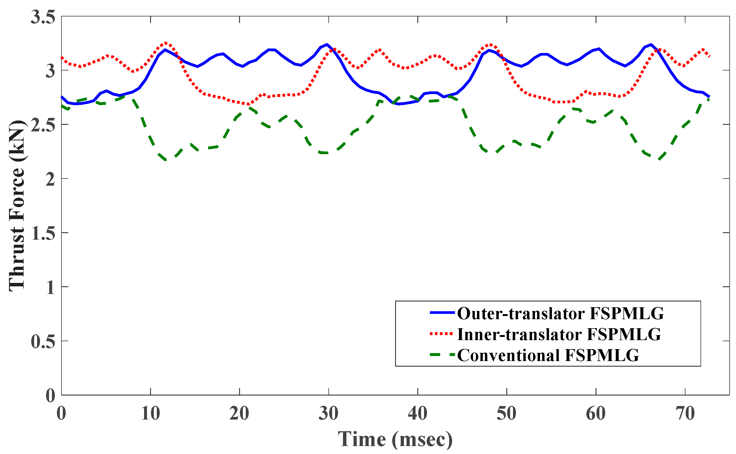
| Thrust force (N) | 2986.5 | 2970.5 | 2490.1 |
| Average shear stress (kN/m3) | 37.33 | 37.13 | 31.12 |
| Force ripple (%) | 18.43 | 19.03 | 24.2 |
| Output power (W) | 2986.5 | 2970.5 | 2490.1 |
| Copper loss (W) | 287 | 269.8 | 266.9 |
| Hysteresis loss (W) | 28.7 | 27.4 | 19.9 |
| Eddy current loss (W) | 2.5 | 2.3 | 1.6 |
| Total iron loss (W) | 31.2 | 29.7 | 21.5 |
| Power factor | 0.511 | 0.508 | 0.403 |
| Efficiency (%) | 0.9037 | 0.9084 | 0.8962 |
Disclaimer/Publisher’s Note: The statements, opinions and data contained in all publications are solely those of the individual author(s) and contributor(s) and not of MDPI and/or the editor(s). MDPI and/or the editor(s) disclaim responsibility for any injury to people or property resulting from any ideas, methods, instructions or products referred to in the content. |
© 2023 by the authors. Licensee MDPI, Basel, Switzerland. This article is an open access article distributed under the terms and conditions of the Creative Commons Attribution (CC BY) license (https://creativecommons.org/licenses/by/4.0/).
Share and Cite
Farahani, E.F.; Baker, N.J.; Mahmouditabar, F. An Innovative H-Type Flux Switching Permanent Magnet Linear Generator for Thrust Force Enhancement. Energies 2023, 16, 5976. https://doi.org/10.3390/en16165976
Farahani EF, Baker NJ, Mahmouditabar F. An Innovative H-Type Flux Switching Permanent Magnet Linear Generator for Thrust Force Enhancement. Energies. 2023; 16(16):5976. https://doi.org/10.3390/en16165976
Chicago/Turabian StyleFarahani, Ehsan Farmahini, Nick J. Baker, and Farshid Mahmouditabar. 2023. "An Innovative H-Type Flux Switching Permanent Magnet Linear Generator for Thrust Force Enhancement" Energies 16, no. 16: 5976. https://doi.org/10.3390/en16165976