Article

Research on the Energy Management Strategy of a Hybrid Energy Storage Type Railway Power Conditioner System

1
School of Automation and Electrical Engineering, Lanzhou Jiaotong University, Lanzhou 730070, China
2
Laboratory of Opto-Technology and Intelligent Control Ministry of Education, Lanzhou Jiaotong University, Lanzhou 730070, China
3
China Railway Lanzhou Bureau Group Co., Ltd., Lanzhou 730000, China
4
Xi’an Rail Transit Group Co., Ltd., Operation Branch, Xi’an 710000, China
*
Author to whom correspondence should be addressed.
Energies 2023, 16(15), 5759; https://doi.org/10.3390/en16155759
Submission received: 2 June 2023 / Revised: 1 July 2023 / Accepted: 29 July 2023 / Published: 2 August 2023

Abstract

:
High-speed railways generate a large amount of regenerative braking energy during operation but this energy is not utilized efficiently. In order to realize the recycling of regenerative braking energy of high-speed railways, the hybrid energy storage type railway power conditioner (RPC) system is proposed. The working principle and the control strategy of the system are studied. The energy management strategy consisting of a hybrid energy storage system charging and discharging strategy and variational modal decomposition (VMD) power allocation strategy is proposed. Three system operation modes are proposed: the power of the hybrid energy storage system is decomposed by VMD and an interrelationship number is proposed to determine the lithium battery and supercapacitor power. The hardware-in-the-loop test experiments are conducted by the StarSim power electronics small-step real-time simulator from Modeling Tech and the validation analysis is carried out on MATLAB/Simulink with the actual measurement data of a traction substation on the Lanzhou–Xinjiang line. The results verify that the proposed strategy can effectively recycle the regenerative braking energy, realize the peak-shaving effect on the load, and reduce the energy consumption of the train.

1. Introduction

Nowadays, “low-carbon development” has become an important concept in global economic development and the implementation of low-carbon transportation is one of the important measures [1,2]. High-speed railways have become an important way of low-carbon transportation due to their advantages of energy saving, environmental protection, and convenience [3,4]. As the mileage of high-speed railway operations increases, energy consumption by railways will continue to rise. The train generates regenerative braking energy during braking which can amount to 10–30% of the traction energy in some special sections [5,6,7]. There is a huge potential for energy recovery in the operation of trains. Its energy consumption can be regulated by utilizing regenerative braking energy [8,9,10], reducing carbon emissions, and contributing to emission peak and carbon neutrality targets.
With the progression of energy storage technology, it is increasingly used in high-speed railway [11,12,13,14]. The authors of [15] investigated the conformity of wayside energy storage systems in the Italian railway infrastructure to use regenerative braking energy. The potential impact of energy consumption in the railway infrastructure and energy savings in wayside units using battery storage systems was assessed [16]. The application of energy storage technology was then reviewed in Japanese DC and AC railways which has grown from the first lithium battery installed in a traction power system in 2006 to more than 20 energy storage systems today. In China, megawatt-scale flywheel energy storage technology has also been successfully applied to electrified railways to reduce electricity consumption.
The main regenerative braking schemes for trains are energy consumption [17], energy supply [5], and energy storage [18,19,20]. RPC has the advantage of load shifting and flexibility [21,22]. For AC railways, energy storage solutions based on the RPC [23,24] can improve the power quality while utilizing regenerative braking energy. It has therefore received considerable attention. The authors in [25,26] proposed an RPC system topology based on supercapacitor energy storage and investigated its control strategy. However, most of the energy storage type solutions are single storage media; due to the total amount of regenerative braking energy, via single storage it is difficult to achieve high power and regenerative braking energy utilization. Hybrid energy storage systems consisting of both power density and energy density energy storage media [27,28] become a research hotspot at home and abroad.
The energy management strategy is responsible for coordinating the energy flow between the hybrid energy storage system and the traction power supply system; the allocation of power commands is a key issue in the energy management control of the hybrid energy storage system [29,30]. A proper power allocation strategy not only improves energy utilization but also extends the life of the energy storage medium. The authors in [31] reviewed the current energy management strategy for railway energy storage systems based on thresholds and allocation ratios. Moreover, [32] proposed a two-layer model of the energy management system of railway traction substations based on HESS daily dispatch and HESS classification; the system was formulated as a mixed integer linear programming model which improved the economics of the measure. The authors of [33] proposed an optimal operation formula for the optimal operation of a hybrid energy storage system in high-speed trains with renewable energy sources. The railway hybrid energy storage system and its control strategy were proposed in [34] and the first-order low-pass filtering algorithm was used for the internal power distribution of the hybrid energy storage system. The authors of [35] used the discrete Fourier transform for power allocation in a hybrid energy storage system for high-speed railways. Based on the operating properties of traction loads, a fixed-cycle control energy management strategy that takes advantage of the regular operating characteristics of high-speed railways was proposed. In the hybrid energy storage system for high-speed railways, the flow of energy between the hybrid energy storage system, the traction power system, and the distribution of power within the hybrid energy storage system are key issues.
The hybrid energy storage type RPC system is constructed and the system principle is analyzed. The control strategy of the system is studied, which includes the energy management strategy, the RPC control strategy, and the DC/DC control strategy. In the energy management strategy, in order to determine the target power of the hybrid energy storage system and the target power of the storage medium, the hybrid energy storage system charging and discharging strategy and VMD power allocation strategy is proposed. The proposed strategy is tested in hardware-in-the-loop on the StarSim power electronics small step real-time simulator from Modeling Tech and analyzed on MATLAB/Simulink with the measured data of a traction substation on the Lanzhou–Xinjiang line.

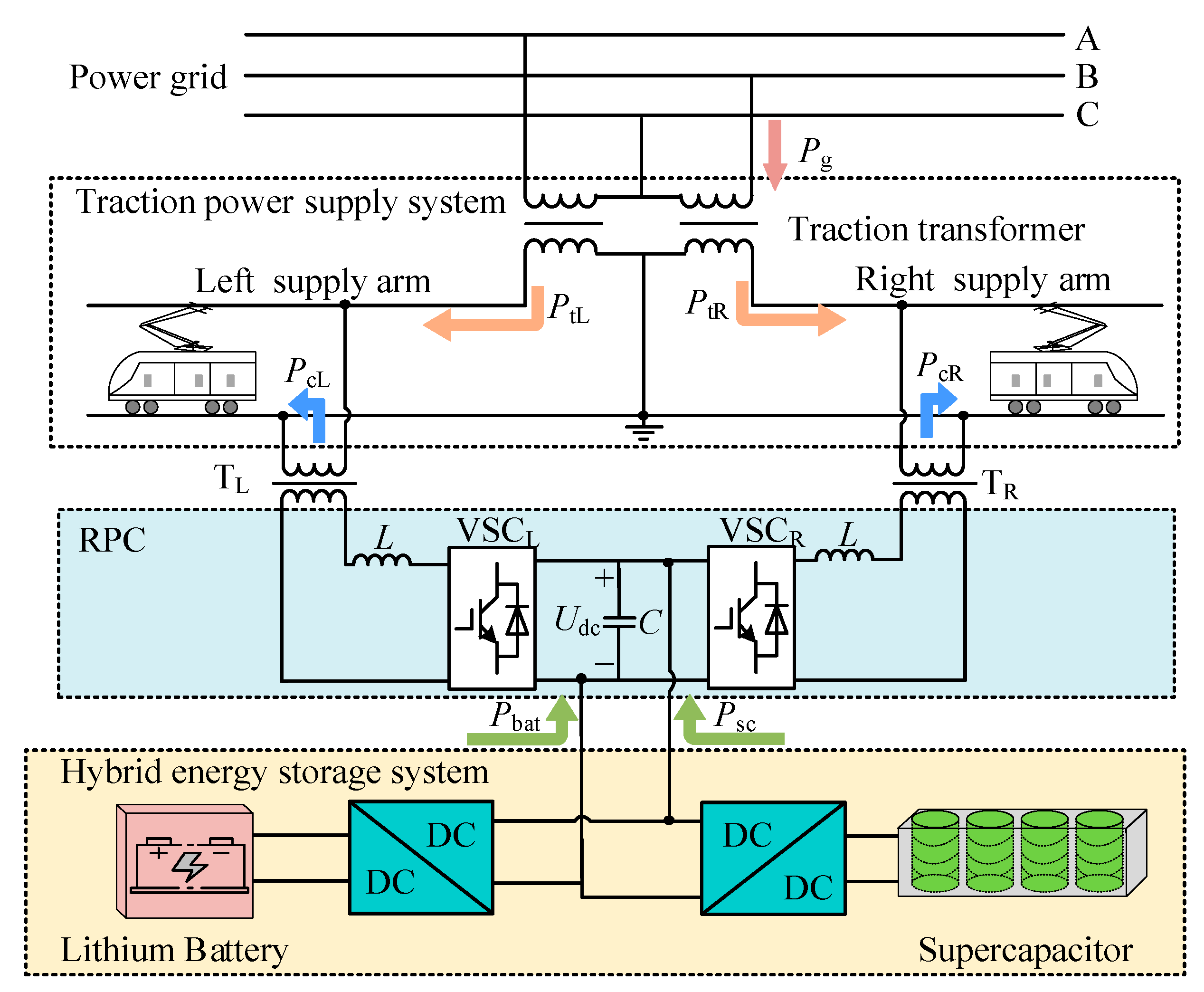
2. Hybrid Energy Storage Type RPC System

2.1. System Structure

The structure diagram of the hybrid energy storage type RPC system is shown in Figure 1. Pg is the power of the grid and PtL and PtR are the active power of the left and right supply arm load from the traction substation, respectively. PcL and PcR are the active power compensated by the RPC to the left and right supply arms, respectively; Udc is the intermediate DC-side capacitance voltage; Pbat and Psc are the power of the lithium battery and the supercapacitor, respectively.
The hybrid energy storage type RPC system in Figure 1 consists of the traction power supply system, the RPC, and the hybrid energy storage system. A hybrid energy storage system consists of energy storage media and bi-directional DC/DC converters. Lithium battery is an energy storage medium which has high energy density and low cost. However, it is slow to respond and has a low number of cycles. A supercapacitor has high power density, fast response times, and high cycle times, but at a high cost. A supercapacitor is a power storage medium that has high power density, fast response times, and high life cycles, but is expensive. Lithium battery energy storage and supercapacitor energy storage are more mature and stable compared to flywheel energy storage and superconducting energy storage. Therefore, a lithium battery and supercapacitor are chosen as the energy storage media of the hybrid energy storage system, which can take full advantage of both media to meet the high power and high energy demand of regenerative braking.
In the traction power supply system, the 330 kV three-phase voltage is converted to a single-phase 27.5 kV voltage by a v/v traction transformer. The RPC consists of the VSCL converter, the VSCR, and the intermediate DC capacitor and is connected to the left and right supply arms via two step-down transformers. The lithium battery and the supercapacitor are connected to the DC link capacitor through their respective bidirectional DC-DC converters and the energy management strategy is used to control the charging and discharging of the energy storage medium to achieve regenerative braking energy utilization.

2.2. System Operating Principle

The energy relationship within the system is shown in Figure 1. Pes is defined as the total output power of the hybrid energy storage system and PL and PR as the active power of the load of the left and right supply arms, respectively. PZ is the total active power of the load, which is equal to the sum of the active power of the load in the left and right supply arms. If the direction of the arrow in Figure 1 is specified as the positive direction of power flow, the power relationship between the system components is:
{ P Z = P L + P R = P tL + P tR + P cL + P cR P g = P tL + P tR P es = P cL + P cR = P bat + P sc
The active power P′L of the load in the left supply arm and the active power P′R of the load in the right supply arm after compensation by the hybrid energy storage type RPC system are:
P L = P R = P L + P R + P es 2
Then, the active power PcL and PcR compensated by RPC to the left and right supply arms are:
{ P cL = P L P R 2 + P es 2 P cR = P L P R 2 + P es 2

3. Hybrid Energy Storage Type RPC System Control Strategy

The control strategy of the hybrid energy storage type RPC system consists of an energy management strategy, RPC control strategy, and DC/DC converter control strategy; its control scheme is shown in Figure 2.

3.1. Energy Management Strategy for Hybrid Energy Storage RPC System

The interaction between the energy of the energy storage system and the energy flow of the traction power system depends on the energy management strategy. The energy management strategy includes the charging and discharging strategy of the hybrid energy storage system and the VMD power allocation strategy.

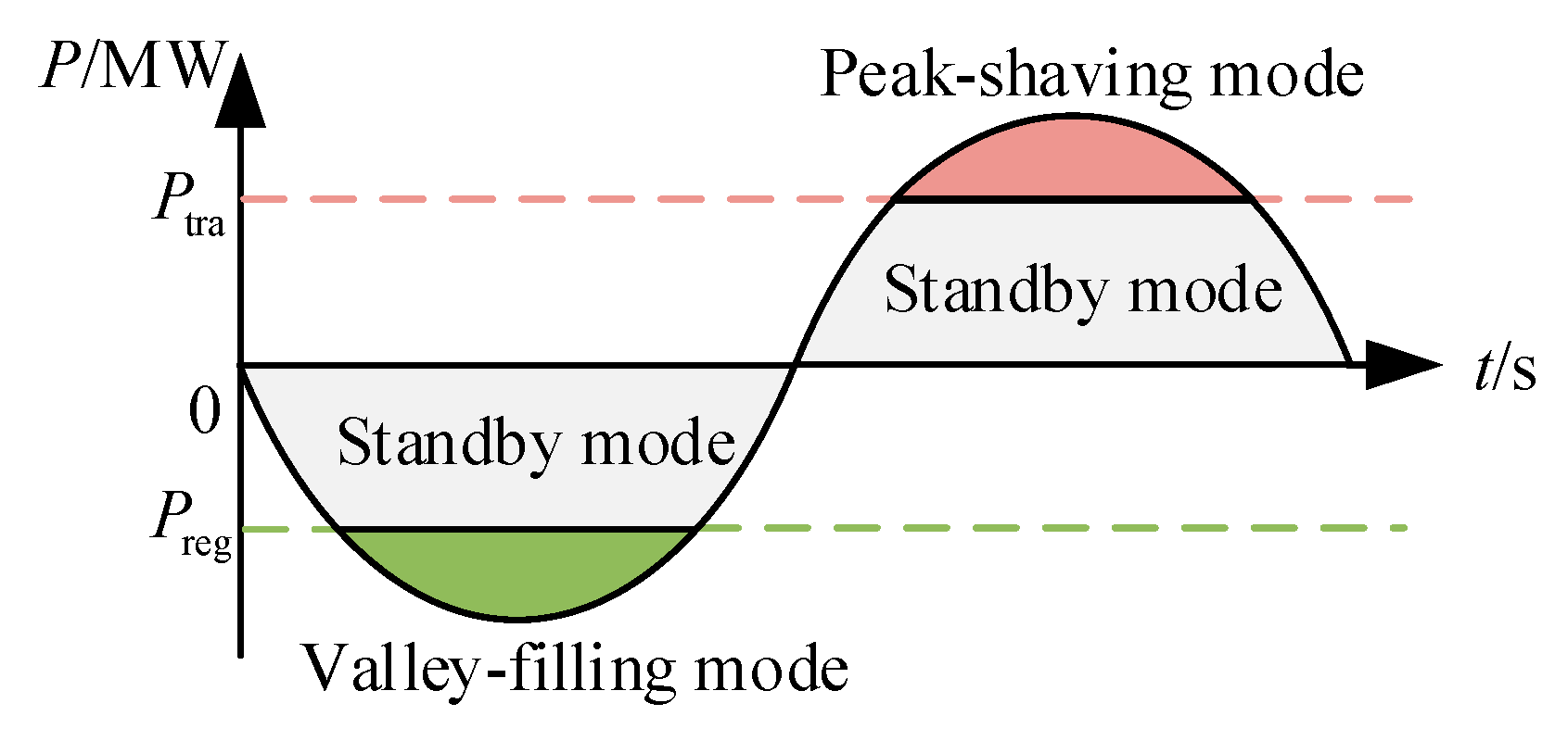
3.1.1. The Charging and Discharging Strategy of the Hybrid Energy Storage System

The charging and discharging strategy of the hybrid energy storage system is responsible for the reasonable allocation of energy between the hybrid energy storage system and the traction power supply system to achieve the function of peak shaving and valley filling. In Figure 3, according to the total active power of the load PZ and the state of charge of the energy storage medium, the charging and discharging strategy of hybrid energy storage system divides the system into three operations. The analysis of each mode is as follows:
A positive value for the tractive effort of the system and a negative value for the braking effort of the system are defined. The absorbed power value of the energy storage medium is positive and the released power value is negative. For ease of presentation, Ptra and Preg are defined as the system peak-shaving and valley-filling thresholds, respectively. Pes_max is the maximum power of the hybrid energy storage system; Pbat_max is the maximum power of the lithium battery; and Psc_max is the maximum power of the supercapacitor. SOCbat is the state of charge of the lithium battery; SOCbat_min and SOCbat_max are the minimum and maximum values of the state of charge of the lithium battery, respectively; SOCsc is the state of charge of the supercapacitor; and SOCsc_min and SOCsc_max are the minimum and maximum values of the state of charge of the supercapacitor, respectively.
  • Valley-filling mode
When PZPreg and SOCbat or SOCsc is less than the respective state of charge maximum, the hybrid energy storage system absorbs regenerative braking energy, which can be specifically divided into the following two cases. When PZ < Pes_max, the hybrid energy storage system is charged with Pes_max and the remaining energy is returned to the grid. When −Pes_maxPZPreg, the charging power of the hybrid energy storage system is −PZ and no energy is returned to the grid. Therefore, the target power P es 1 * of the hybrid energy storage system in this mode is:
P es 1 * = min ( P Z , P es _ cmax )
2.
Standby mode
If Preg < PZ < Ptra or SOCbat and SOCsc are not in the normal operating range, the energy storage system is in standby mode and its target power P es 2 * is:
P es 2 * = 0
3.
Peak-shaving mode
When PZPtra and SOCbat or SOCsc is greater than the respective state of charge minimum, the hybrid energy storage system releases energy and reduces the peak load. This can be subdivided into the following two cases. When PtraPZ < Ptra + Pes_max, the discharge power of the hybrid energy storage system is PZPtra. When PZPtra + Pes_max, the hybrid energy storage system discharge power is Pes_max. Therefore, the target power value P es 3 * of the energy storage system in this mode is:
P es 3 * = max ( P tra P Z , P es _ dmax )
The operating modal determination conditions are shown in Table 1.

3.1.2. The VMD Power Allocation Strategy

VMD can effectively avoid modal mixing and achieve the separation of similar frequency components [36]. In order to make the lithium battery and the supercapacitor in the hybrid energy storage system more responsive to the power demand of the trains, the VMD-based hybrid energy storage power allocation strategy is proposed so as to separate the high and low-frequency power of the hybrid energy storage system.
  • Variational modal decomposition
The optimal solution of the variational model is searched iteratively and its constrained variational model is shown in (7):
{ min { u k } , { ω k } { k = 1 K t [ ( δ ( t ) + j π t ) u k ( t ) ] e j ω k t 2 2 }   s . t .   k = 1 K u k = P es * ( t )
where {uk} is the set of IMFs obtained by VMD of the target power P es * (t) of the hybrid energy storage system; {ωk} is the set of IMF center frequencies; K is the number of IMFs; and δ(t) is the pulse function.
The optimal solution to the above variational problem is solved by introducing the Lagrange multiplier function with the expression:
L ( { u k } , { ω k } , { λ } ) = α k = 1 K t [ ( δ ( t ) + j π t ) u k ( t ) ] e j ω k t 2 2 + P es * ( t ) k = 1 K u k ( t ) 2 2 + λ ( t ) , P es * ( t ) k = 1 K u k ( t )
where λ is the Lagrange multiplicative operator and α is the quadratic penalty factor.
The IMF is obtained by iteratively updating uk, wk, and λ using the alternating multiplier algorithm to solve (7). The modal components and their central frequencies are then obtained by the Fourier transform as follows:
{ u ^ k n + 1 ( ω ) = P ^ es * ( ω ) i k u ^ i ( ω ) + λ ^ ( ω ) 2 1 + 2 α ( ω ω k ) 2 ω k n + 1 = 0 ω | u ^ k ( ω ) | 2 d ω 0 | u ^ k ( ω ) | 2 d ω
where u ^ k n + 1 ( ω ) , P ^ es * ( ω ) , λ ^ ( ω ) , and u ^ i ( ω ) are the sequences of u k n + 1 ( ω ) , P es * ( ω ) , λ ( ω ) , and u i ( ω ) after Fourier transformation, respectively; u ^ k n + 1 ( ω ) is the Wiener filter of the current residual; and ω k n + 1 is the current IMF center frequency.
The Lagrange multiplicative operator is updated with:
λ ^ n + 1 ( ω ) = λ ^ n ( ω ) + τ [ P ^ es * ( ω ) k = 1 K u ^ k n + 1 ( ω ) ]
During the iterative solution process, each IMF and its center frequency are continuously updated until the entire cycle is completed after the iteration stop condition is satisfied, which is:
k = 1 K u ^ k n + 1 u ^ k n 2 2 u ^ k n 2 2 < e
where e is the specified determination accuracy and e > 0.
2.
Energy storage medium target power determination
The VMD decomposition yields IMF components from low to high frequency. The number of interrelationships is defined and reflects the correlation between IMFs: the larger the number of interrelationships, the greater the correlation between variables.
R(IMFk, IMFk+1) is defined as the number of interrelationships between connected IMFk and IMFk+1:
R ( IMF k , IMF k + 1 ) = 1 N 1 i = 1 N ( IMF k ( i ) μ IMF k σ IMF k ) ( IMF k + 1 ( i ) μ IMF k + 1 σ IMF k + 1 )
where N is the number of sampling points; σ IMF k and μ IMF k are the mean and standard deviation of IMFk, respectively; and σ IMF k + 1 and μ IMF k + 1 are the mean and standard deviation of IMFk+1, respectively.
The IMFk corresponding to the minimum value of the number of relationships is chosen as the partition. The IMF1~k is reconstructed as the low-frequency power PesL of the energy storage system. By comparing it with the maximum power of the lithium battery, the target power value of the lithium battery is obtained as follows:
P bat * = { max ( P esL , P es _ dm ax ) , P esL 0 min ( P esL , P es _ cm ax ) , P esL > 0
Then, the target power of the supercapacitor is the total power minus the target power of the lithium battery and the expression is as follows:
P sc * = P es * P bat *

3.2. RPC Control Strategy

The RPC enables the flow of active power in the left and right supply arms while performing reactive power compensation so that the active power in the left and right arms is balanced. The RPC control strategy consists of RPC compensation current calculation and converter control.
  • RPC compensation current calculation
The instantaneous voltages of the grid are [7]:
{ u A = 2 U sin ( ω t ) u B = 2 U sin ( ω t 2 π 3 ) u C = 2 U sin ( ω t + 2 π 3 )
where U is the rms value of the grid voltage.
The instantaneous voltages uL and uR of the left and right supply arms are [7]:
{ u L = 2 U L sin ( ω t π 6 ) u R = 2 U R sin ( ω t π 2 )
where UL and UR are the rms values of the left and right supply arms voltages, respectively.
The instantaneous load currents of the supply arms are made up of fundamental currents and harmonic currents [37]. The instantaneous load currents iL and iR of the left and right supply arms are as follows:
{ i L = 2 I L sin ( ω t π 6 φ L ) + h = 2 2 I Lh sin ( h ω t + φ Lh ) i R = 2 I R sin ( ω t π 2 φ R ) + h = 2 2 I Rh sin ( h ω t + φ Rh )
where IL and IR are the rms values of the left and right supply arms fundamental currents, respectively; ILh and IRh are the rms values of the hth harmonic current of the left and right supply arms, respectively; and φLh and φRh are the hth harmonic phases of the left and right supply arms, respectively.
Multiplying the instantaneous voltage and the instantaneous current of the supply arms, the instantaneous power PLi and PRi of the supply arms are obtained as follows:
{ P Li = u L × i L = U L I L cos φ L U L I L cos ( 2 ω t π 3 ) cos φ L U L I L sin ( 2 ω t π 3 ) sin φ L + h = 2 2 U L I Lh sin ( h ω t + φ Lh ) sin ( ω t π 6 ) P Ri = u R × i R = U R I R cos φ R U R I R cos ( 2 ω t π ) cos φ R U R I R sin ( 2 ω t π ) sin φ R + h = 2 2 U R I Rh sin ( h ω t + φ Rh ) sin ( ω t π 2 )
The instantaneous power all contains DC and AC components which are passed through a low-pass filter (LPF) to filter out the AC components and obtain the active power PL and PR of the supply arms as:
{ P L = U L I L cos φ L P R = U R I R cos φ R
Combined with (2), the fully compensated currents of the left and right supply arms, i L and i R , are the following:
{ i L = 2 2 P L 3 U L sin ( ω t ) i R = 2 2 P R 3 U R sin ( ω t 2 3 π )
Then, the compensation currents, i c L * and i c R * , in the left and right supply arms of the hybrid energy storage RPC system are:
{ i cL * = i L i L = 2 2 P L 3 U L sin ( ω t ) i L i cR * = i R i R = 2 2 P R 3 U R sin ( ω t 2 3 π ) i R
The RPC compensation current detection diagram is shown in Figure 4. According to Equation (18), the left and right supply arm voltages and currents obtained from the supply arm end are multiplied and passed through LPF to obtain the supply arm active power. According to Equation (2), the active power of the supply arm after compensation is obtained by calculating it with the power of the hybrid energy storage system Pes. Then, the supply arm voltages UL and UR are divided to obtain the compensated supply arm active current. Subsequently, the compensated supply arm active current is multiplied by 2 3 3 according to the instantaneous power theory to obtain the compensated supply total arm current. After multiplying the synchronization signals, the compensation current setpoints i c L * and i c R * are obtained by subtracting them from the respective supply arm currents.
2.
Converter control
The diagram of the converter control strategy is shown in Figure 5. In order to achieve proper RPC operation and access to the hybrid storage system, the voltage on the intermediate DC side needs to be stable. Therefore, through the voltage outer loop control, the difference between the target value of DC voltage U dc * and the actual value of voltage Udc is PI adjusted and then multiplied by the synchronous signals sin(ωt-p/6) and sin(ωt-p/2) of uL and uR, respectively, to obtain the voltage outer loop stabilization current. The target values of the compensation currents i cL * and i cR * are multiplied by the step-down transformer ratio k to obtain the target values of the compensation currents on the low voltage side. The target values of the low-side compensation currents and the voltage outer loop stabilization currents are added to obtain the actual compensation current target values i cL 1 * and i cR 1 * for each converter. The difference between these values and the actual compensation values is then used to generate pulse waves via PWM to control the left and right converters of the RPC.

3.3. DC/DC Converter Control Strategy

The DC/DC converter uses current loop control and its control strategy diagram is shown in Figure 6. The target power P bat * of the lithium battery is divided by the lithium battery voltage Ubat to obtain the target current value I bat * . The difference between the actual value of the current loop feedback inductor current Ibat and I bat * is PI adjusted to control the bidirectional DC/DC converter by generating a pulse wave by PWM. Similarly, the bidirectional DC/DC converter on the supercapacitor side is controlled to enable charging and discharging of the energy storage medium.

4. Test Verification and Analysis

To verify the effectiveness of the control strategy and energy management strategy of the hybrid energy storage RPC system, a hardware-in-the-loop test is conducted by the StarSim power electronics small-step real-time simulator from Modeling Tech. The measured power supply arm of a traction substation on the Lanzhou–Xinjiang line is used as simulation data in MATLAB/Simulink for verification. The model parameters are shown in Table 2.

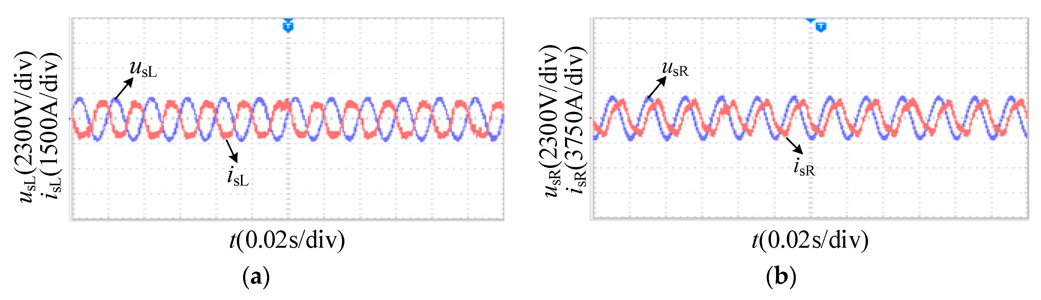
4.1. StarSim Real-Time Verification

The StarSim experimental platform diagram is shown in Figure 7. The built main circuit model is loaded into the StarSim host computer with a simulation step of 1 μs. The control circuit is loaded into the FPGA of the emulator by StarSim HIL (hardware-in-the-loop) through compilation and the model I/O interface is configured with the emulator I/O interface to realize the input and output connection between the main circuit and the control circuit; the experimental waveform is observed by an oscilloscope. The operating conditions are set to PL = 5 MW, PH = 3 MW, P bat * = 2 MW, and P sc * = 1 MW. The intermediate DC side voltage is obtained as shown in Figure 8 and the intermediate DC side voltage is stabilized in the range of 3175 V–3245 V.
The waveforms of the left and right converter voltages, usL and usR, and currents, isL and isR, are obtained as shown in Figure 9 and the left and right converters can operate normally under the set working conditions to realize the energy flow.

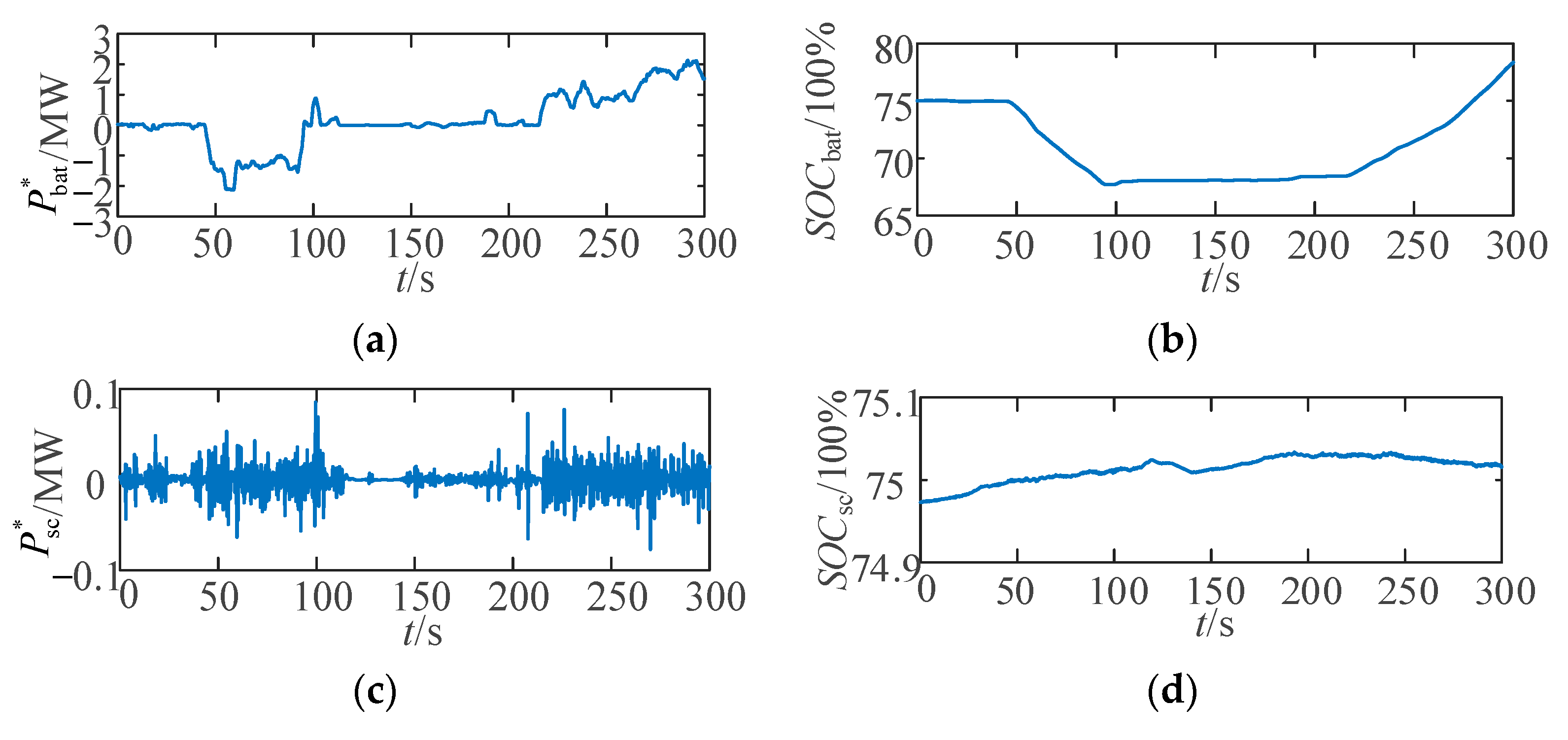
4.2. MATLAB Simulation Verification

The simulation is verified in MATLAB/Simulink based on the measured power arm data (sampling frequency of 0.25 s/time). The PL and PR waveforms of the left and right power supply arms and the PZ waveform of the total active power of the load are shown in Figure 10.
Figure 11 shows the waveform of the hybrid energy storage system target power P es * obtained by the charging and discharging strategy of the hybrid energy storage system.
VMD needs to set the IMF quantity K. K has a large impact on the decomposition effect of VMD. The center frequency difference at K = 7 is too large and there is an under-decomposition problem. The similar frequencies occur at K = 9 and over-decomposition occurs. Therefore, K is set equal to 8 and the IMF spectrum is obtained according to the decomposition result as shown in Figure 12.
Based on the results of VMD, the number of interrelationships between each connected IMF is calculated and the results are shown in Table 3. According to Table 3, R(IMF6, IMF7) is the smallest and IMF6 has the smallest correlation with IMF7, so IMF1–6 is selected for low-frequency power reconstruction. Thus, the target power values, P bat * for the lithium battery and P sc * for the supercapacitor, are obtained. The power waveforms are shown in Figure 13a,b. The lithium battery takes up most of the power and the supercapacitor takes up the frequently fluctuating power, thereby buffering the lithium battery discharge process. The state of charge of the lithium battery and the supercapacitor are shown in Figure 13c,d.
The power waveforms of the left and right supply arms before and after compensation are shown in Figure 14. The load imbalance of the supply arms is reduced by the energy flow of the hybrid energy storage type RPC system.
In Figure 15, PT and P′T are the required power values of the traction substation before and after compensation, respectively. The maximum value of traction substation compensation power is reduced from 9.344 MW to 7.289 MW, effectively reducing the traction substation compensation power.
According to the analysis of Figure 13, Figure 14 and Figure 15, it can be obtained that from 0 s to 99 s most of the working conditions of PZ ≥ 5 MW, the system is in the peak-shaving mode, and the hybrid energy storage system releases energy. Whereas, from 114 s to ~145 s the system is in standby mode, the hybrid energy storage system is not working, and the RPC is responsible for transferring the power of the left and right supply arms. As for the period of 215 s~300 s, PZ ≤ 0 MW, the system is in the valley-filling mode, the SOCbat of lithium battery is in the rising state, and the hybrid energy storage system stores energy and regulates the railway energy consumption.
The regenerative braking energy savings rate h is defined as:
η = E st E sum
where Est is the stored regenerative braking energy and Esum is the total regenerative braking energy of the left and right supply arms.
According to the calculation, the total regenerative braking energy in the supply arms load is 64.348 kW·h, the system stores 46.182/kW·h regenerative braking energy, and the regenerative braking energy saving rate is 71.77%. Combined with the analysis in Figure 10, Figure 11, Figure 12, Figure 13, Figure 14 and Figure 15, the proposed energy management strategy achieves accurate power allocation of the hybrid energy storage system, makes effective use of regenerative braking energy, and achieves peak shaving and valley filling.

5. Conclusions

The hybrid energy storage type RPC system is constructed and has wide application prospects in regenerative braking energy rich lines such as long ramps. It is composed of a traction power supply system, RPC, and a hybrid energy storage system; the energy flow relationship of the hybrid energy storage type RPC system is analyzed. A system control strategy is investigated, including the energy management strategy, RPC control strategy, and DC/DC converter control strategy.
In the energy management strategy, the charging and discharging strategy of the hybrid energy storage system divides the system into three modes: the peak-shaving mode, standby mode, and valley-filling mode, realizing peak-shaving and valley-filling for the load. The VMD power allocation strategy uses VMD to decompose the hybrid energy storage system power and determine the high and low-frequency divisions according to the IMF interrelationship number, effectively realizing the high and low-frequency allocation of energy storage power.
The RPC control strategy consisting of compensated current calculation and converter control based on voltage outer and current inner loops is proposed and the DC/DC converter control strategy using a current-loop control is proposed. The proposed strategy achieves the absorption and release of regenerative braking energy, reducing the energy demand of trains and supporting the low-carbon operation of high-speed railways.
In addition, the problem of capacity configuration optimization for hybrid energy storage systems can be further explored in future work.

Author Contributions

Methodology, Y.W. and Y.G.; software, Y.W. and Y.G.; validation, Y.W., Y.G., and X.C.; formal analysis, X.C.; investigation, D.J. and Y.Z.; resources, D.J. and J.X.; data curation, Y.Z.; writing—original draft preparation, Y.G.; writing—review and editing, Y.W. and X.C. All authors have read and agreed to the published version of the manuscript.

Funding

This research was funded by the National Natural Science Foundation of China, grant number 52067013, and the Natural Science Key Foundation of Science and Technology Department of Gansu Province, grant numbers 21JR7RA280, 22JR5RA318, and 22JR11RA162.

Data Availability Statement

Not applicable.

Conflicts of Interest

The authors declare no conflict of interest.

References

  1. Cutrignelli, F.; Saponaro, G.; Stefanizzi, M.; Torresi, M.; Camporeale, S.M. Study of the effects of regenerative braking system on a hybrid diagnostic train. Energies 2023, 16, 874. [Google Scholar] [CrossRef]
  2. Chen, Q.J.; Wang, Q.W.; Zhou, D.Q.; Wang, H.G. Drivers and evolution of low-carbon development in China’s transportation industry: An integrated analytical approach. Energy 2023, 262, 125614. [Google Scholar] [CrossRef]
  3. Barros, L.A.M.; Martins, A.P.; Pinto, J.G. Balancing the active power of a railway traction power substation with an sp-RPC. Energies 2023, 16, 3074. [Google Scholar] [CrossRef]
  4. Teng, J.; Li, L.K.; Jiang, Y.J.; Shi, R.F. A review of clean energy exploitation for railway transportation systems and its enlightenment to China. Sustainability 2022, 17, 10740. [Google Scholar] [CrossRef]
  5. Hu, H.T.; Chen, J.Y.; Ge, Y.B.; Huang, W.L.; Liu, L.Z.; He, Z.Y. Research on regenerative braking energy storage and utilization technology for high-speed railways. Proc. CSEE 2020, 40, 246–256+391. [Google Scholar] [CrossRef]
  6. Lu, Q.W.; He, B.B.; Wu, M.Z.; Zhang, Z.C.; Luo, J.T.; Zhang, Y.K.; He, R.K.; Wang, K.Y. Establishment and analysis of energy consumption model of heavy-haul train on large long slope. Energies 2018, 11, 965. [Google Scholar] [CrossRef] [Green Version]
  7. Guo, Y.; Chen, X.Q.; Wang, Y.; He, Y.Q.; Yang, H.; Chang, Z.N. Negative sequence optimization compensation strategy for energy storage type railway power conditioner considering grid voltage imbalance. High Volt. Eng. 2023, 49, 772–780. [Google Scholar] [CrossRef]
  8. Chen, J.Y.; Hu, H.T.; Ge, Y.B.; Huang, W.L.; He, Z.Y. An energy storage system for recycling regenerative braking energy in high-speed railway. IEEE Trans. Power Deliv. 2020, 36, 320–330. [Google Scholar] [CrossRef]
  9. Frilli, A.; Meli, E.; Nocciolini, D.; Pugi, L.; Rindi, A. Energetic optimization of regenerative braking for high speed railway systems. Energy Convers. Manag. 2016, 129, 200–215. [Google Scholar] [CrossRef]
  10. Ceraolo, M.; Lutzemberger, G.; Meli, E.; Pugi, L.; Rindi, A.; Pancari, G. Energy storage systems to exploit regenerative braking in DC railway systems: Different approaches to improve efficiency of modern high-speed trains. J. Energy Storage 2018, 16, 269–279. [Google Scholar] [CrossRef]
  11. Li, T.; Shi, Y.B. Application of MMC-RPC in high-speed railway traction power supply system based on energy storage. Appl. Sci. 2022, 12, 10009. [Google Scholar] [CrossRef]
  12. Şengör, İ.; Kılıçkıran, H.C.; Akdemir, H.; Kekezoǧlu, B.; Erdinç, O.; Catalão, J.P.S. Energy management of a smart railway station considering regenerative braking and stochastic behaviour of ESS and PV generation. IEEE Trans. Sustain. Energy 2018, 9, 1041–1050. [Google Scholar] [CrossRef]
  13. Li, Q.Z.; Wang, X.J.; Huang, X.H.; Zhao, Y.; Liu, Y.W.; Zhao, S.F. Research on flywheel energy storage technology for electrified railway. Proc. CSEE 2019, 39, 2025–2033. [Google Scholar] [CrossRef]
  14. Li, T.; Zhou, Y.J.; Wu, M.L.; He, T.T. A new low-frequency oscillation suppression method based on EMU on-board energy storage device. IEEE Access 2021, 9, 22304–22316. [Google Scholar] [CrossRef]
  15. Alfieri, L.; Battistelli, L.; Pagano, M. Impact on railway infrastructure of wayside energy storage systems for regenerative braking management: A case study on a real Italian railway infrastructure. IET Electr. Syst. Transp. 2019, 9, 140–149. [Google Scholar] [CrossRef]
  16. Hayashiya, H.; Yokokawa, S.; Iino, Y.; Kikuchi, S.; Suzuki, T.; Uematsu, S.; Sato, N.; Usui, T. Regenerative energy utilization in ac traction power supply system. In Proceedings of the 2016 IEEE International Power Electronics and Motion Control Conference (PEMC), Varna, Bulgaria, 25–28 September 2016; IEEE: Piscataway, NJ, USA, 2016. [Google Scholar] [CrossRef]
  17. Zhou, F.Y.; Tang, Z.H.; Tian, Z. Research on comprehensive utilization technology of regenerative braking energy for heavy haul railway. In Proceedings of the 2023 5th Asia Energy and Electrical Engineering Symposium (AEEES), Chengdu, China, 23–26 March 2023; IEEE: Piscataway, NJ, USA, 2023; pp. 1574–1581. [Google Scholar] [CrossRef]
  18. Yuan, M.; Tian, L.J.; Jiang, T.; Hu, R.B.; Cui, X.J. Research on the capacity configuration of the “flywheel+ lithium battery” hybrid energy storage system that assists the wind farm to perform a frequency modulation. J. Phys. Conf. Series. IOP Publ. 2022, 2260, 012026. [Google Scholar] [CrossRef]
  19. Ma, Q.; Lei, Z.Y.; Guo, Q.; Yang, Z.J.; Luo, R.J.; Yao, Y.Y. Optimal scheduling of energy storage system for electrified railroad under carbon trading mechanism. In Proceedings of the 2022 25th International Conference on Electrical Machines and Systems (ICEMS), Chiang Mai, Thailand, 29 November–2 December 2022; pp. 1–6. [Google Scholar] [CrossRef]
  20. Meng, F.Q.; Ye, J.J.; Zhao, J.P. A new power supply mode applicable to Sichuan-Tibet railway. In Proceedings of the 2022 4th International Conference on Power and Energy Technology (ICPET), Beijing, China, 28–31 July 2022; pp. 1046–1051. [Google Scholar] [CrossRef]
  21. Xu, C.P.; Han, Y.; Li, Q.; Chen, W.R.; Fu, W.X. Research on coordinated control method of PV and battery access traction power supply system based on RPC. In Proceedings of the 2020 IEEE Sustainable Power and Energy Conference (iSPEC), Chengdu, China, 23–25 November 2020; pp. 173–179. [Google Scholar] [CrossRef]
  22. Deng, W.L.; Dai, C.H.; Han, C.B.X.; Chen, W.R. Research progress of railway power conditioner. Proc. CSEE 2020, 40, 4640–4655. [Google Scholar]
  23. Che, C.; Wang, Y.W.; Lu, Q.W.; Peng, J.J.; Liu, X.H.; Chen, Y. An effective utilization scheme for regenerative braking energy based on power regulation with a genetic algorithm. IET Power Electron. 2022, 15, 1392–1408. [Google Scholar] [CrossRef]
  24. Luo, P.; Li, Q.R.; Zhou, Y.; Ma, Q.; Zhang, Y.; Peng, Y.S.L.; Sun, J.H. Multi-application strategy based on railway static power conditioner with energy storage system. IEEE Trans. Intell. Transp. Syst. 2021, 22, 2140–2152. [Google Scholar] [CrossRef]
  25. Chen, M.W.; Cheng, Y.L.; Cheng, Z.; Zhang, D.Y.; Lv, Y.B.; Liu, R.F. Energy storage traction power supply system and control strategy for an electrified railway. IET Gener. Transm. Distrib. 2020, 14, 2304–2314. [Google Scholar] [CrossRef]
  26. Cui, G.P.; Luo, L.F.; Liang, C.G.; Hu, S.J.; Li, Y.; Cao, Y.J.; Xie, B.; Xu, J.Z.; Zhang, Z.W.; Liu, Y.X.; et al. Supercapacitor integrated railway static power conditioner for regenerative braking energy recycling and power quality improvement of high-speed railway system. IEEE Trans. Transp. Electrif. 2019, 5, 702–714. [Google Scholar] [CrossRef]
  27. Ma, Q.; Guo, X.; Luo, P.; Zhang, Z.W. Coordinated control strategy design of new type railway power regulator based on super capacitor energy storage. Trans. China Electrotech. Soc. 2019, 34, 765–776. [Google Scholar] [CrossRef]
  28. Xiao, Z.; Sun, P.F.; Wang, Q.Y.; Zhu, Y.Q.; Feng, X.Y. Integrated optimization of speed profiles and power split for a tram with hybrid energy storage systems on a signalized route. Energies 2018, 11, 478. [Google Scholar] [CrossRef] [Green Version]
  29. Qu, K.; Yuan, J.X. Optimization research on hybrid energy storage system of high-speed railway. IET Gener. Transm. Distrib. 2021, 15, 2835–2846. [Google Scholar] [CrossRef]
  30. Wang, X.; Luo, Y.B.; Qin, B.; Guo, L.Z. Power dynamic allocation strategy for urban rail hybrid energy storage system based on iterative learning control. Energy 2022, 245, 123263. [Google Scholar] [CrossRef]
  31. Luo, J.M.; Wei, X.G.; Gao, S.B.; Huang, T.; Li, D. Summary and outlook of capacity configuration and energy management technology of high-speed railway energy storage system. Proc. CSEE 2022, 42, 7028–7051. [Google Scholar] [CrossRef]
  32. Liu, Y.L.; Chen, M.W.; Lu, S.F.; Chen, Y.Y.; Li, Q.Z. Optimized sizing and scheduling of hybrid energy storage systems for high-speed railway traction substations. Energies 2018, 11, 2199. [Google Scholar] [CrossRef] [Green Version]
  33. Aguado, J.A.; Antonio, J.S.R.; Sebastián, D.L.T. Optimal operation of electric railways with renewable energy and electric storage systems. IEEE Trans. Smart Grid 2016, 9, 993–1001. [Google Scholar] [CrossRef]
  34. Deng, W.L.; Dai, C.H.; Han, C.B.X.; Chen, W.R. Back-to-back hybrid energy storage system of electric railway and its control method considering regenerative braking energy recovery and power quality improvement. Proc. CSEE 2019, 39, 2914–2924. [Google Scholar]
  35. Tang, S.D.; Huang, X.H.; Li, Q.Z.; Yang, N.Q.; Liao, Q.Y.; Sun, K. Optimal sizing and energy management of hybrid energy storage system for high-speed railway traction substation. J. Electr. Eng. Technol. 2021, 16, 1743–1754. [Google Scholar] [CrossRef]
  36. Dragomiretskiy, K.; Zosso, D. Variational mode decomposition. IEEE Trans. Signal Process. 2014, 62, 531–544. [Google Scholar] [CrossRef]
  37. Wang, Y.; He, Y.Q.; Chen, X.Q.; Zhao, M.M.; Xie, J. A layered compensation optimization strategy of energy storage type railway power conditioner. Arch. Electr. Eng. 2022, 71, 5–20. [Google Scholar] [CrossRef]
Figure 1. Structure diagram of the hybrid energy storage type RPC system.
Energies 16 05759 g001
Figure 2. Hybrid energy storage type RPC control strategy.
Energies 16 05759 g002
Figure 3. Hybrid energy storage system operating modes.
Energies 16 05759 g003
Figure 4. RPC compensation current detection diagram.
Energies 16 05759 g004
Figure 5. RPC control strategy.
Energies 16 05759 g005
Figure 6. DC/DC converter control strategy.
Energies 16 05759 g006
Figure 7. StarSim hardware-in-the-loop experiment platform diagram.
Energies 16 05759 g007
Figure 8. Intermediate DC side voltage.
Energies 16 05759 g008
Figure 9. RPC converter voltage and current waveforms. (a) Left converter voltage and current waveforms; (b) Right converter voltage and current waveforms.
Energies 16 05759 g009
Figure 10. Left and right supply arms load power. (a) Active power of the left and right supply arms; (b) Total active power of the load.
Energies 16 05759 g010
Figure 11. Target power of the hybrid energy storage system.
Energies 16 05759 g011
Figure 12. IMF spectrogram.
Energies 16 05759 g012
Figure 13. Power and state of the charge curve of the lithium battery and supercapacitor. (a) Lithium battery power; (b) Lithium battery state of charge; (c) Supercapacitor power; (d) Supercapacitor state of charge.
Energies 16 05759 g013
Figure 14. Comparison of the power of left and right power supply arms before and after compensation. (a) The power of the left arm before and after compensation; (b) The power of the right arm before and after compensation.
Energies 16 05759 g014
Figure 15. Traction substation power before and after compensation.
Energies 16 05759 g015
Table 1. Operating modal determination conditions.
Operating ModesJudgment ConditionsTarget Power
valley-filling P Z P tra and ( S O C bat > S O C bat _ min or S O C sc > S O C sc _ min ) P es 1 * = min ( P Z , P es _ cmax )
standby P reg < P Z < P tra or S O C bat , S O C sc are   not   in   the   normal   operating   range P es 2 * = 0
peak-shaving P Z P reg   and ( S O C bat < S O C bat _ max   or S O C sc < S O C sc _ max ) P es 3 * = max ( P tra P Z , P es _ dmax )
Table 2. Simulation parameters of the hybrid energy storage type RPC model.
SystemsParametersValues
Power systemVoltage330 kV
Traction substationv/v transformer ratio330 kV/27.5 kV
RPCStep-down transformer ratio27.5 kV/1.5 kV
Filter inductor/H1.1 × 10−3
Capacitor/F10 × 10−3
Intermediate DC side voltage Udc/V3200
Hybrid energy storage system Lithium batterySupercapacitor
Rated capacity/MWh0.250.09
Capacitor/F--210
Rated power/MW31
SOC interval/%20–8010–90
Modal determination thresholdPeak-shaving mode/MW5
Valley-filling mode/MW0
Table 3. IMF cross-correlation coefficient.
Cross-Correlation CoefficientValues
R(IMF2, IMF3)0.137
R(IMF3, IMF4)0.077
R(IMF4, IMF5)0.109
R(IMF5, IMF6)0.065
R(IMF6, IMF7)0.010
R(IMF7, IMF8)0.044
Disclaimer/Publisher’s Note: The statements, opinions and data contained in all publications are solely those of the individual author(s) and contributor(s) and not of MDPI and/or the editor(s). MDPI and/or the editor(s) disclaim responsibility for any injury to people or property resulting from any ideas, methods, instructions or products referred to in the content.

