Review

A Review on Analysis Methods and Research Status of Hysteresis Motor

1
School of Electrical Engineering and Automation, Harbin Institute of Technology (HIT), Harbin 150001, China
2
Chongqing Research Institute of HIT, Chongqing 401135, China
*
Author to whom correspondence should be addressed.
Energies 2023, 16(15), 5715; https://doi.org/10.3390/en16155715
Submission received: 30 June 2023 / Revised: 22 July 2023 / Accepted: 27 July 2023 / Published: 31 July 2023
(This article belongs to the Topic Future Generation Electric Machines and Drives)

Abstract

:
A hysteresis motor produces output torque through the hysteresis effect of magnetic materials. It has the advantages of a simple structure, high-speed operation, high temperature resistance, low noise and self-starting capability. It can be applied to some special occasions requiring high speed and high stationarity. However, its disadvantage is low torque density, low efficiency and low power factor. The permanent magnet hysteresis motor is a compromise of the characteristics of permanent magnet motor and hysteresis motor, and it can be self-starting in the case of having a torque density comparable to that of a permanent magnet motor. In addition, there are some new structures of hysteresis motors, which open up the direction for innovative applications. Due to the complexity of magnetic properties, the calculation methods and dynamic models of hysteresis motors and permanent magnet hysteresis motors are special and also depend on the research of hysteresis materials and hysteresis models. This paper starts from the principle and classification of the hysteresis motor, and different structures and the corresponding analysis methods are reviewed. The motors with new structures and new methods are emphasized, the innovation and contribution of existing research are summarized, and the development trend of hysteresis motors is described.

1. Introduction

Hysteresis refers to the phenomenon that when the ferromagnetic material is magnetized or demagnetized, its magnetization intensity not only depends on the strength of the external magnetic field but also depends on the historical state of magnetization. For materials with different “magnetic hardness”, hysteresis characteristics have different performance. For soft magnetic materials, the hysteresis loop is very narrow, which can be approximated as a nonlinear single-value curve as shown in Figure 1a. The hysteresis loop of hard magnetic materials is very wide, and the BH characteristics are linear when the external magnetic field is small as shown in Figure 1b. For hysteresis materials (also known as hysteresis alloy, semi-hard magnetic materials), the BH loop width is between soft magnetic materials and hard magnetic materials as shown in Figure 1c. For a motor whose rotor is made of hysteresis materials, when the rotating magnetic field is applied through the stator current, the magnetization state of the rotor lags behind the field generated by the stator, which will cause the magnetic field of the airgap to be distorted, thus producing hysteresis torque. This is the operating principle of the traditional hysteresis motor (HM) as shown in Figure 2. And its typical structure is shown in Figure 3.
In the traditional hysteresis motor, the torque is mainly due to the hysteresis effect. In addition, hysteresis torque can also be combined with other torque sources, such as adding hysteresis materials in the permanent magnet (PM) motor to make a permanent magnet hysteresis motor (PMHM). As long as the motor contains hysteresis torque in the design, it is called a generalized hysteresis motor as shown in Figure 4. For different types of hysteresis motors, only the rotors are different, and the stators are all traditional polyphase stators which can also be used in induction motors or permanent magnet motors. According to the difference in operating characteristics, their applications are also different. The following will focus on the traditional hysteresis motor and the permanent magnet hysteresis motor. If there are no special instructions, the hysteresis motor refers to the traditional hysteresis motor without a permanent magnet.
As a special type of motor, the hysteresis motor can be applied to some special occasions. Since its operating principle was proposed in the early 20th century, it has been rapidly developed, and in recent years, it has widely been of interest [1,2].
On the one hand, the hysteresis motor has low torque fluctuation, smooth operation and low noise, which makes it suitable for occasions where precise speed or position control is required, such as lithography machines. Researchers from the Massachusetts Institute of Technology (MIT) have applied maglev linear hysteresis motors to lithography machines to achieve contactless linear transport [3,4]. In addition, hysteresis motors have a unique advantage, which is due to the low outgassing properties of the hysteresis rotor [5,6]. For PM motors, the PMs can outgas in a vacuum environment, and these gas particles will eventually attach to other components, such as the wafer in the lithography machine, sensitive electronic, optical components, etc., so as to affect their operation. Therefore, the PMs need to be encapsulated, which requires a relatively complicated secondary design. The rotor of the hysteresis motor is a solid alloy material, which does not have this problem. Similarly, for the equipment in the space station, such as the satellite attitude controller, as well as the medical parts and medical drive equipment implanted in the human body, there are also strict requirements for cleanliness and low outgassing, so hysteresis motors have natural advantages in this respect [7].
On the other hand, the hysteresis material has high mechanical strength and high temperature resistance such that the hysteresis motor can work in a high temperature environment and can run to a very high speed. The turbocharger is an important part used to increase engine power and reduce exhaust gas emissions, and is widely used in different types of vehicles [8]. Electric turbochargers have a maximum speed of more than 100 krpm, and need to withstand high engine temperatures. Scholars from Polytechnic University of Turin in Italy compared the ultimate tensile strength and maximum operating temperature of a variety of hysteresis alloys with permanent magnet materials, indicating the application prospect of hysteresis motors in high-speed and high-temperature scenarios [9]. In addition, this characteristic of hysteresis motor allows it to be applied in high-speed spindle motor and high-end manufacturing fields.
In addition, the hysteresis motor has some other advantages: its rotor structure is simple and reliable with good symmetry, and its rotor dynamic stability is unmatched. Hysteresis motors can be self-started and have nearly constant output torque during the starting of constant frequency.
However, small output torque, low power factor and low efficiency are the inherent defects of the hysteresis motor, which greatly limit its application. Insert PMs in the rotor of hysteresis motor, or replace the rotor core of PM motor with hysteresis material, and then the permanent magnet hysteresis motor (PMHM) is obtained. PMHM has the advantages of high power density and high efficiency similar to the PM motor, and has a self-starting ability using the characteristics of hysteresis torque, usually suitable for industrial occasions, such as fans and pumps [10,11]. The typical structure of PMHM is shown in Figure 5. The shape and location of its PMs are diverse, including flat-shaped, V-shaped, and so on; see Section 3 for details. Usually, different electromagnetic designs make the motor compromise between the starting torque and synchronous torque. However, PMHM loses the advantages of the simple structure and high rotor strength of the traditional hysteresis motor, and because of the demagnetization of the permanent magnet at a high temperature, the temperature tolerance of the motor is reduced. Therefore, the PMHM is closer to the PM motor in all aspects and different from the hysteresis motor in terms of the advantages and disadvantages, application occasions, key problems and so on. The benchmark of PMHM is usually an induction motor, both of which can be started at constant frequency and can work without a position sensor. Compared with the induction motor, PMHM has a higher torque density and lower noise, can run synchronously and more stably [10,12].
In addition, the reluctance effect can also be used to improve the output torque of the hysteresis motor, that is, adding a magnetic barrier on the hysteresis ring, so that the magnetic resistance of the d-axis and the q-axis is different, thus producing a reluctance torque; its typical structure is shown in Figure 6 [13,14]. There are few research works on the reluctance hysteresis motor (RHM), and there has been no relevant research recently. For its in-depth analysis and performance evaluation, it is still very lacking.
The application of various types of hysteresis motors is shown in Table 1, which summarizes representative research results in terms of publication year, country/region, research institution, motor performance and so on. As shown in the table, there are various types of hysteresis motors involving different structures and different types of materials. The torque of the hysteresis motor is usually very small, and the speed can be very high. The torque of the PMHM is relatively considerable.
This paper discusses the different structures of hysteresis motor, respectively. In Section 2, the structure, principle, electromagnetic calculation model and application of the traditional hysteresis motor are introduced. In Section 3, the analytical model, design method and development status of PMHM are introduced. In Section 4, the new structures of the hysteresis motor are introduced. And in Section 5, two key issues related to hysteresis motors, namely hysteresis materials and hysteresis models, are explained. Conclusions and future directions are at the end of the paper.

2. Traditional Hysteresis Motor

The rotor of the traditional hysteresis motor is usually a solid ring or a disk made of hysteresis alloy. Hysteresis torque is the main output torque and usually much larger than eddy current torque.

2.1. Development History

In 1881, physicist James Ewing discovered the phenomenon of magnetic hysteresis and coined the term “hysteresis”. His discovery had a great impact on the study of magnetism in Britain. Since then, researchers at Cambridge University have worked to popularize the electromagnetic theory of ferromagnetic substances. The researchers then showed that the area of the hysteresis loop is proportional to the amount of the energy that hysteresis loses over one magnetization cycle [20], that is, E loss ( in joules ) = V × H d B .
As for the operating principle of hysteresis motor, Steinmetz is one of the original discoverers. When he studied the hysteresis loss in the transformer, he found that the hysteresis phenomenon not only causes loss but also produces torque when applied to alternating current motor [21,22]. He gave the conclusion as follows: when the motor is at rest, the torque generated is proportional to the hysteresis loss; in asynchronous operation, the power provided to the rotor is divided into two parts, where one part is the hysteresis loss, proportional to the slip, the other part is the output mechanical power, proportional to the speed. However, the manufacture of hysteresis motors was not completed at that time.
In 1918, Livens revealed an electromagnetic formula that became the basis for hysteresis motors [23]. In 1940, B. R. Teare published a paper on the torque generated by the hysteresis motor [2]. He used the principle of virtual displacement to derive the hysteresis torque of the motor in detail, and explained the transformation of the hysteresis loop during the dynamic operation of the motor. Although these conclusions were obtained under some ideal assumptions, and the calculation methods were not advanced enough at that time such that the calculation is not accurate, the qualitative analysis of the characteristics of the hysteresis motor is sufficient.
The early applications of the hysteresis motor include the record player and electric clock, and later, an important application was the tape recorder. In the 1960s and 1970s, the tape recorder was an important device for data recording, storage and reading [24]. At that time, an important problem to be solved was how to make the tape feed at a constant speed. Since the hysteresis motor can be self-started, once an AC current is applied in the winding, the motor accelerates smoothly and runs at a synchronous speed.
When the information recording developed from sound to image, the limitations of the magnetic tape became apparent, and the application of the hysteresis motor was also limited. So, less research was conducted for a period of time. Later, media information was recorded on compact discs and hard disks, which were driven by permanent magnet motors. Nowadays, because of its excellent characteristics, the hysteresis motor has been applied in a variety of special scenes, and its research value has been explored again.

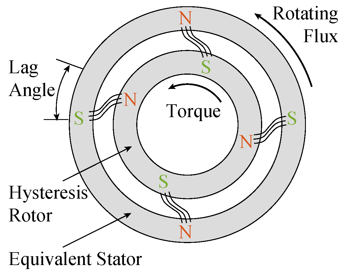
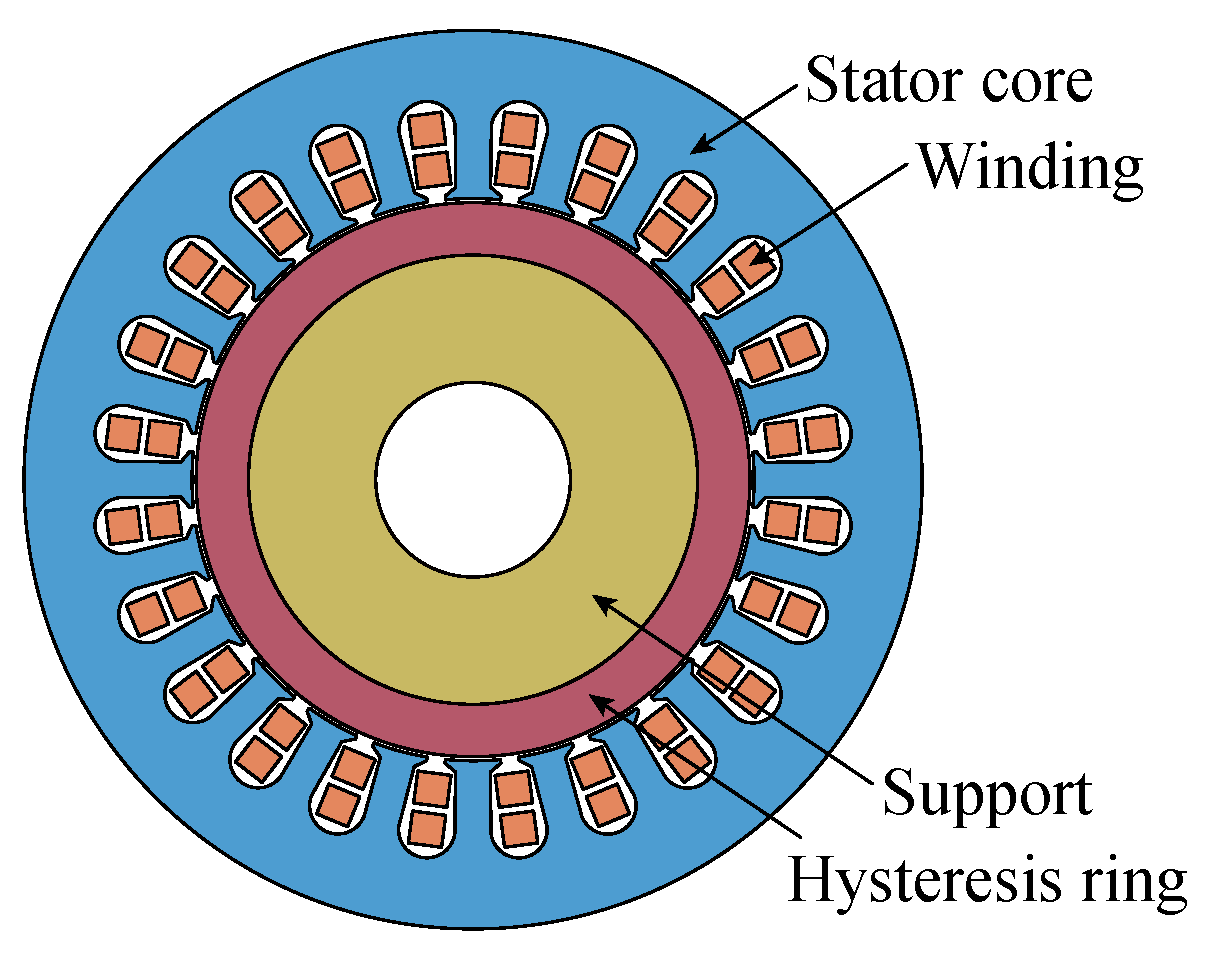
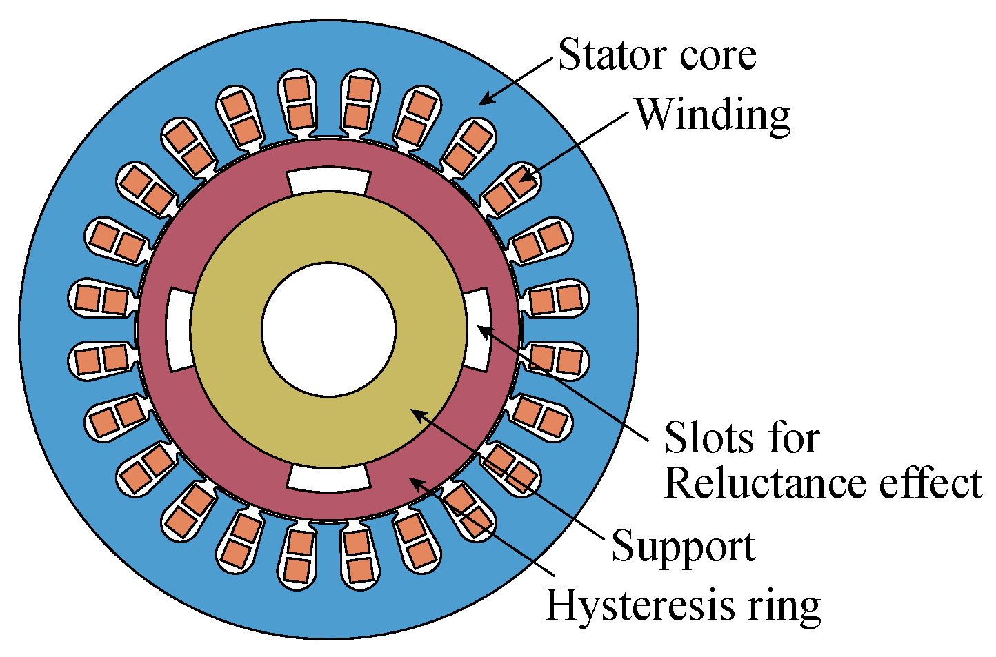
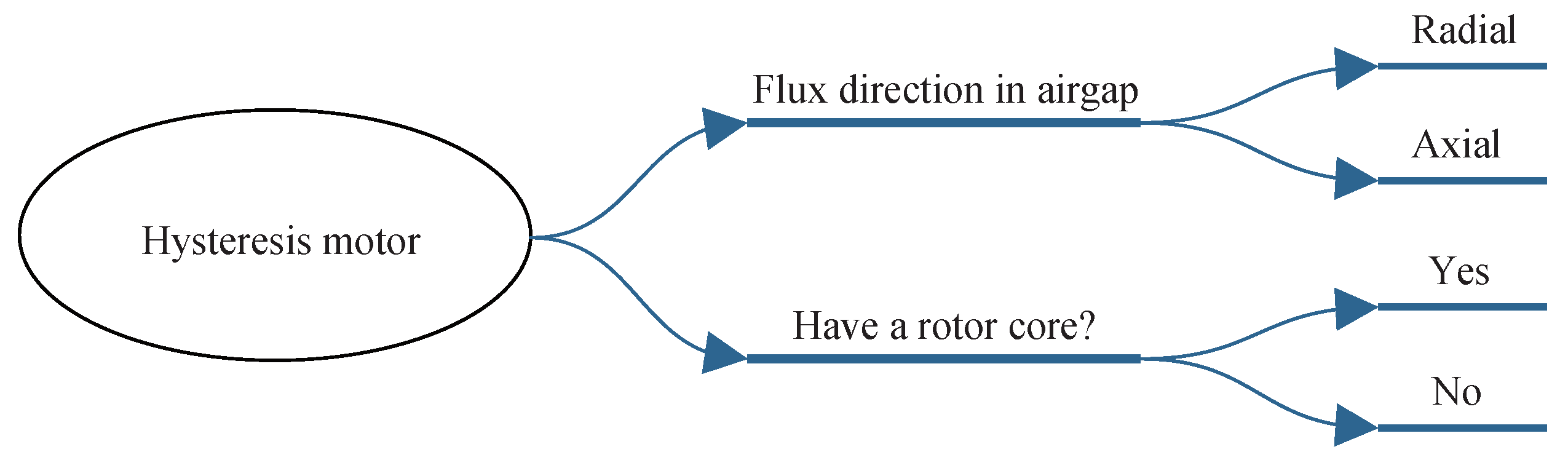
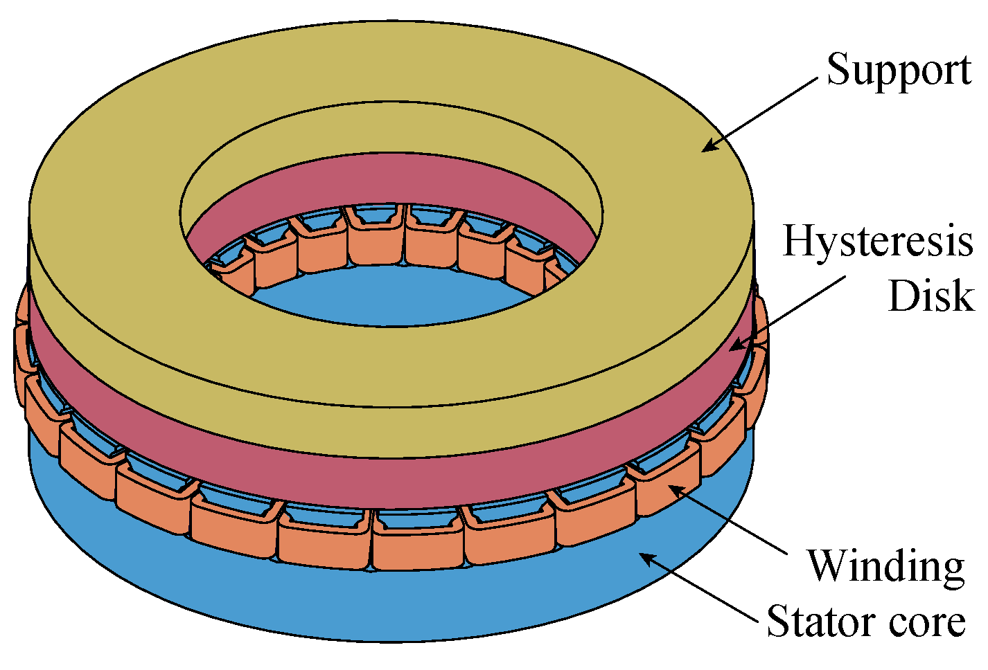
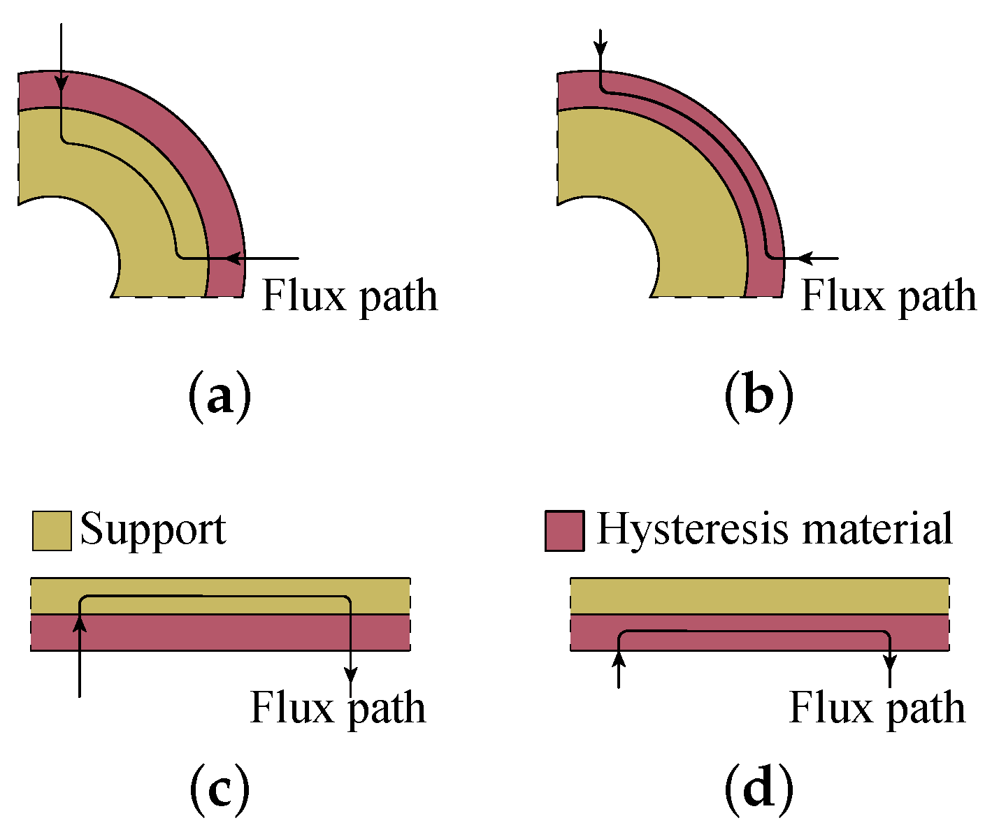
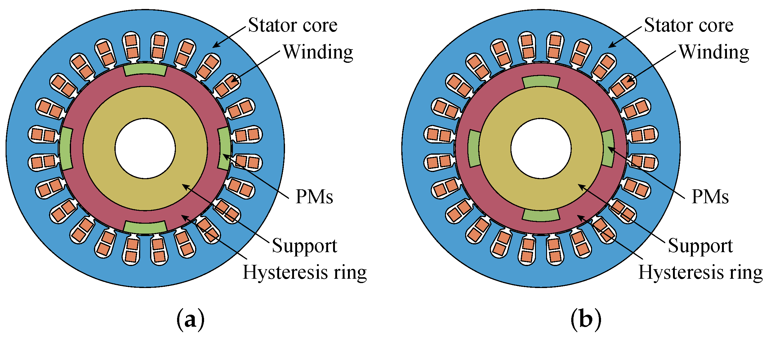
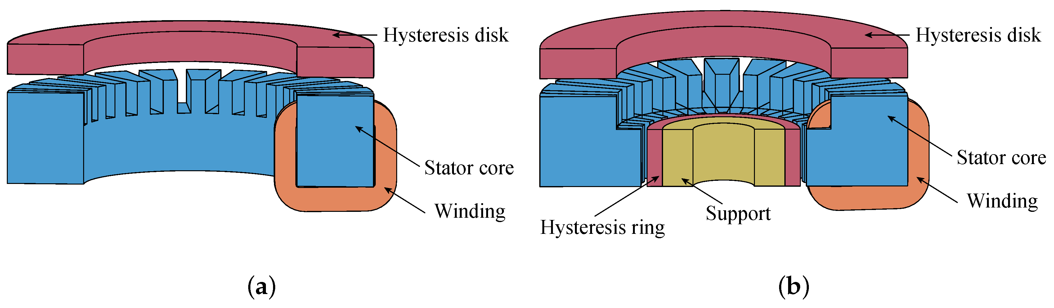
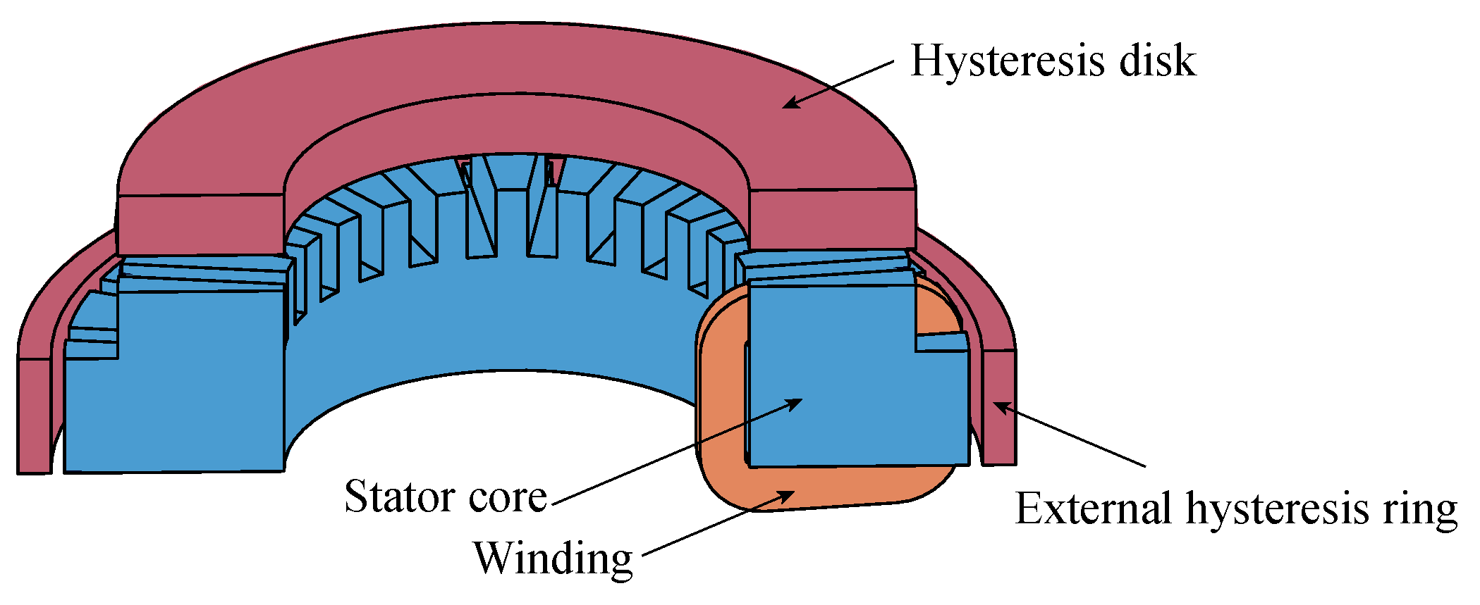
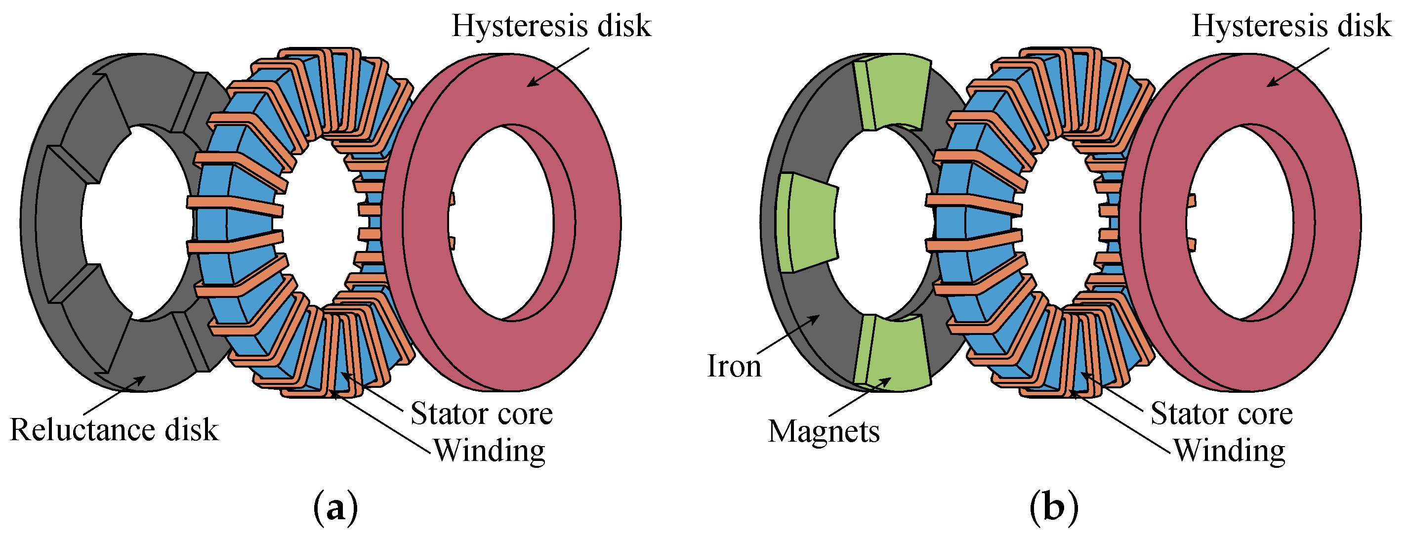
2.2. Structure and Classification

Since the operation principle of the hysteresis motor was discovered, a variety of structures have been proposed and studied, and the different characteristics brought by different structures have broadened the application of the hysteresis motor. The main categories of the hysteresis motor are shown in Figure 7.
Similar to other motors, according to the direction of the airgap flux, hysteresis motors can be divided into the radial flux hysteresis motor (RFHM, Figure 3) and axial flux hysteresis motor (AFHM, Figure 8). Like other motors, the axial structure is flatter, and in theory can achieve higher torque density and operating efficiency [25], while the radial motor is easier to reach high speed due to the smaller moment of inertia. The stator of the hysteresis motor has no difference from the permanent magnet motor or induction motor. For the axial flux hysteresis motor, a stator-slotless design or even a stator-coreless design can be used, which is less common in the radial flux hysteresis motor.
For hysteresis motors, the rotor core makes a big difference. If there is a core, which means the support in Figure 3 and Figure 8 is a ferromagnetic material, the magnetic flux will pass through the hysteresis material and enter the rotor core as shown in Figure 9a,c because the permeability of the core is usually higher than that of the hysteresis material. At this time, the magnetic flux in the hysteresis material is mainly the radial component (for RFHM) or the axial component (for AFHM). If there is no rotor core, that is, the support is composed of non-magnetic materials such as aluminum, the magnetic flux will only exist in the hysteresis material as shown in Figure 9b,d. For this case, the magnetic flux in the hysteresis material is mainly the circumferential component (for either RFHM or AFHM), so this motor is also known as the circumferential flux hysteresis motor. Figure 9c,d are the equivalent expansion of the rotor of the AFHM along the circumferential direction. In addition, hysteresis motors can also be specially designed for linear motors [26].
From the statistics of the literature, the case of no rotor core is more common because without the core, the magnetic flux is forced to be in the magnetic material and usually a larger area of hysteresis loop can be obtained, thus making the output torque larger. For AFHM, it is even possible to remove the support to simplify the structure and reduce the weight.
The radial structure is the most basic and the earliest structure that was studied. It was adopted in the paper published by Teare in 1940, and many subsequent studies also adopted this structure. The structure of the radial motor is relatively simple, and the relevant research works mainly focus on the calculation of the magnetic field and the output characteristic.
For AFHM, Ahmad Darabi et al. in Iran have achieved a lot, including slotted [18], slotless [27], stator-coreless [28] structure, etc. And the steady-state equivalent circuit models of these motors were derived, which are only different in the flux path, and their modeling assumptions and theoretical forms are very similar to those shown in Figure 10. On this basis, the relevant simulation and experiment were completed, and the influence of the input voltage, frequency and size on the equivalent circuit parameters and the motor performances was revealed. In addition, the optimal values of parameters such as the hysteresis disk thickness and the ratio of the inner and outer radius can be obtained so as to guide the motor design.

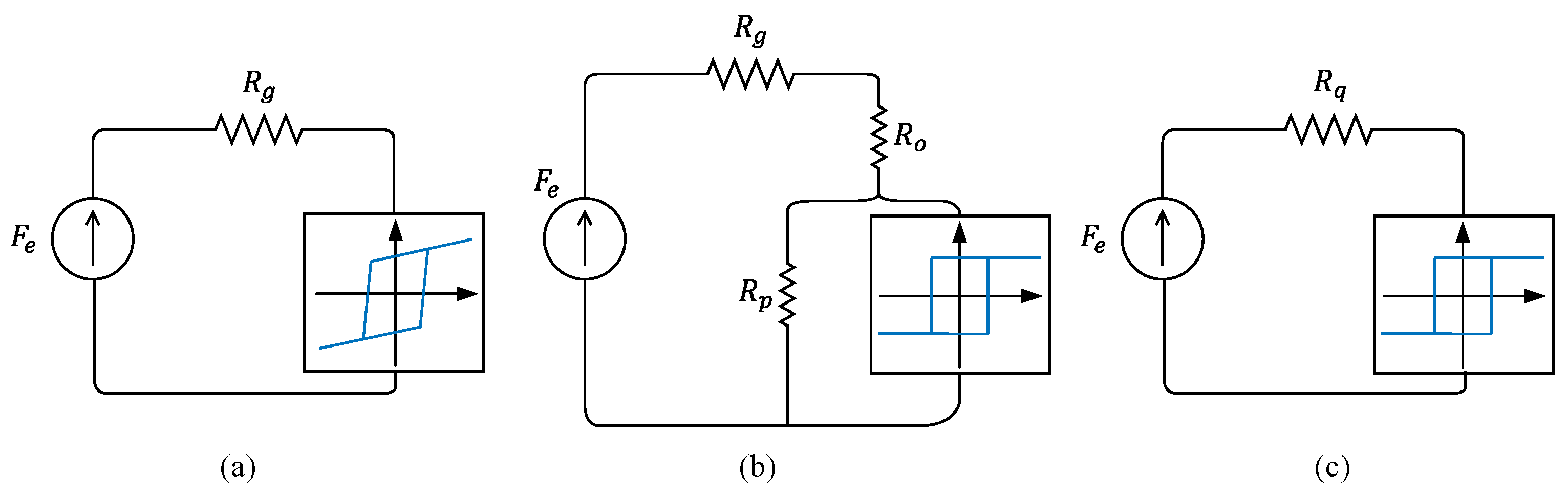
2.3. Calculation and Analysis Methods

Like other types of motors, hysteresis motors must be reasonably designed according to the application. In the design, it is necessary to establish an accurate model to evaluate the performance of the motor with different structures and parameters. The calculation methods of hysteresis motor can be divided into the analytical method, finite element method and experimental method, and the analytical method includes the equivalent circuit method and exact analytical method. The calculation here refers to the steady-state performance of the motor, while the transient performance will be discussed later.
The equivalent circuit method is derived from the magnetic circuit method, and its essence is to specify the main flux path, and then solve the flux density on the path according to the flux continuity law and Ampere loop law. On this basis, the relationship between the current, output torque and input voltage could be deduced. The equivalent circuit model is usually combined with the parallelogram model, ellipse model and other approximate hysteresis loop models (see Section 5.2.1). This method is simple and fast, which can be used to estimate the performance of hysteresis motor and to perform parameter sensitivity analysis.
In 1963, Copeland and Slemon constructed the equivalent circuit model of radial hysteresis motors with and without rotor cores with the parallelogram approximation model under some ideal assumptions [29,30] as shown in Figure 11. Subsequently, the equivalent circuit was solved and analyzed, the relationship between the magnetomotive force and the magnetic flux per unit angle was obtained, and the pull-in performance of the motor was analyzed.
Based on an equivalent circuit model, the slotless and coreless axial flux hysteresis motors have been compared in many aspects [31]. The slotless motor has higher efficiency, and the coreless motor has higher power factor. The coreless motor is suitable for high-frequency applications, while the slotless motor has better performance in almost all middle- and low-frequency applications.
In [32], a unified equivalent circuit model of three kinds of hysteresis motors is given, that is, the RFHM without rotor cores, AFHM with rotor cores and AFHM without rotor cores. Then, the corresponding parameters of the three structures are given respectively, and the derivation process are also given. Then, the situation in the rotating dq coordinate system is explained.
In conclusion, the equivalent circuit model can be used for preliminary estimation of the hysteresis motor performance. It can show the relationship between the size parameters and performance, and can also be used for the transient performance calculation if the dynamic process and mechanical transient equation are taken into account. However, this model cannot show the distribution of the magnetic field in space, and because of the need to specify the magnetic flux path in advance, large errors may exist when the structure is relatively complex and the flux path is difficult to judge in advance.
The exact analytical method [33,34] has high precision and a closed solution, which means to solve Maxwell equations or its simplified form in several subregions, with boundary conditions and initial value conditions. This method is also suitable for the hysteresis motor [35] but it is less used because of the complicated magnetic characteristics of hysteresis material. The exact analytical method can show the distribution of the magnetic field in the motor but it requires a deep mathematical foundation. The solution of this method is shape dependent and needs to be reconsidered once the shape changes, and it has trouble dealing with complex geometric shapes. When the structure is irregular and there are too many regions, the equation is too complex to obtain an analytical solution.
The finite element method is to build a geometric model in simulation software, add electromagnetic excitation, and then just run it to obtain a numerical solution of the magnetic field related to space and time. The finite element method has high accuracy and strong robustness, and can be applied to very complex models. Through finite element simulation, the performance of hysteresis motor can be accurately calculated, including the magnetic field, flux density, current density and loss, and parametric sweeping and structural optimization can also be carried out. However, its disadvantage is its long calculation time, which make it unsuitable for rapid calculation and batch optimization.
There are two kinds of finite element models: magnetostatic model and dynamic model. In the magnetostatic model, the basic magnetization curve connecting each vertex of the hysteresis loop is considered the input, and the magnetostatic simulation is performed, and then the average torque and other properties are obtained through certain post-processing methods [36,37,38]. In [39], the 2D magnetostatic simulation for the radial hysteresis motor is completed with FEMM, and the area of the hysteresis loop of each position is calculated based on the maximum radial and tangential flux density, which can be summed to obtain the average torque. The calculation results are similar to the results by commercial software Ansys. By magnetostatic simulation and post processing, only the average torque can be obtained, not the torque wave with time.
In the dynamic simulation model, the parameters of the hysteresis material can be directly introduced into the finite element model, and then just running the model, the magnetic field and the transient waveform of the torque can be obtained. In [40], the permeability tensor as shown in Equation (1) is used to complete the transient finite element simulation of radial hysteresis motor:
B x B y = μ x x μ x y μ y x μ y y H x H y
It is more common to integrate the JA model (see Section 5.2.3) into the finite element model because of the simplicity of the parameters, high precision and the ability to show the saturation and small hysteresis loop. In [41], the steady torque current characteristics are simulated based on the JA model in COMSOL, and in [42], the transient waveform of speed and torque are obtained by integrating the vector JA model into the finite element model.
For AFHM, if the finite element method is used, 3D simulation must be adopted, which consumes a lot of computing resources, so it has not been reported. There is another method, that is, directly building prototypes for the experiments, and performing analysis by the measurement results of torque, efficiency, power factor and so on. The experimental method is the most direct and the most credible method.
In [43], the author constructs 10 kinds of slotless axial flux hysteresis motor for experiments, and obtains the relationship between the line voltage, input power, starting torque, power factor, efficiency and phase current. The main conclusions are as follows: (1) The structure without a rotor core is better than that with a core. To some extent, the structure without a rotor core is more efficient because the flux density in the hysteresis material is larger, and the area of the corresponding hysteresis loop is larger. (2) If there are two hysteresis disks on both sides the stator, rather than a single disk on one side, the motor will have not any improvement on the performance. (3) Increasing the terminal voltage at synchronous speed will reduce the efficiency of all the motors studied.
The disadvantages of the experimental method are the high cost and the long production time. In addition, neither the finite element nor the experiment can clearly reveal the influence of geometric parameters and excitation conditions on the output performance of the motor. The analytical method with higher accuracy and stronger robustness is still an irreplaceable method for the hysteresis motor design.
Through magnetic field calculation, finite element simulation or experiments, the motor performance can be evaluated so as to guide the motor design. However, the above research works only pay attention to the electromagnetic properties but ignore the temperature and stress field. Taking the interaction between multiple physical fields into consideration to improve the comprehensive performance of the motor is the future direction.

2.4. Dynamic Model

For the hysteresis motor, the hysteresis loop of its rotor material may change in the dynamic process, resulting in the change of its output torque. In addition, it is necessary to study its control theory for smooth speed regulation.

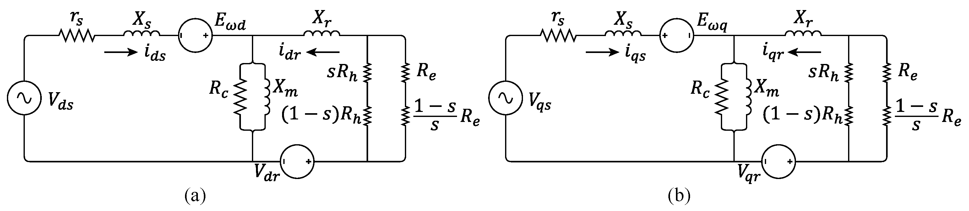
2.4.1. Dynamic Electromagnetic Model

For the analytical calculation of the dynamic process, the common method is still the equivalent circuit. In [32], the equivalent circuit constructed by Miyairi and Kataoka [44] is extended to the rotating dq coordinate, and the dynamic voltage equation related to the rotational speed is given. By the equivalent circuit equation together with the torque equation and the speed equation, the transient process caused by the change of torque and load can be explained.
When the speed increases steadily, the torque remains constant because the hysteresis angle is limited to a certain maximum value (40 in this paper). This is not in line with the usual fact. However, the basic dynamic characteristics is shown in this model; when the synchronous speed is reached, the speed is basically stable, and the torque gradually converges to balance with the load.
Darabi [45] equates the three-phase winding to two phases, and completes the dynamic equivalent circuit as shown in Figure 12. Moreover, the influence of the input voltage on the shape of hysteresis loop is considered, so the equivalent circuit parameters are set to be changing with the input voltage. In this model, the rotor hysteresis is embodied in hysteresis resistance R h and reactance X r , and R e is the eddy current resistance, X m is the magnetized reactance, R c is the iron loss resistance, r s is the stator resistance, and X s is the stator leakage reactance, respectively. The power on R e and s R h is the rotor loss, and the power on ( 1 s ) R e / s and ( 1 s ) R h is the mechanical output power by eddy current and hysteresis. As the speed increases, the hysteresis loss decreases, the hysteresis torque increases, the eddy current loss decreases, and the eddy current torque has a maximum value. The speed and torque curves are then calculated by this model. The motor is initially started at rated voltage, with a load of 0.1 Nm, and then the load step jumps to 0.2 Nm at 4 s; at the same time, the speed drops slightly but soon returns to stability. In [46], a method to improve the response speed of axial flux hysteresis motor is proposed, that is, to attach a thin copper sheet to the bottom of the hysteresis disk, and its eddy current torque can help.
A. Halvaei Niasar [47,48] evaluated the previous equivalent circuit models and proposed an improved equivalent circuit model, which could not only consider the influence of the stator voltage but also the influence of the load torque on the hysteresis angle.
The transient process of the hysteresis motor can also be realized in the simulation software. In [42], the vector JA model is integrated with a 2D finite element model, and the speed and torque of the hysteresis motor are simulated, with considering the coupling of magnetic field and circuit, as well as the mechanical equation. The motor starts from a no-load state and reaches the synchronous speed of 1200 rpm. When the load torque of 0.64 Nm is applied at 0.93 s, transient behavior occurs, and the speed is finally 1190 rpm.
In [49], a time-domain finite-boundary element method using COMSOL is proposed, which avoids the permeability discontinuity in the finite element equation when the rotor is rotating and improves the stability and accuracy of the simulation. The JA model is used in the time-domain simulation for the starting process, and the complex permeability model is used in the frequency domain. The time-domain results are more accurate and reliable, and the frequency model is cheaper to calculate.
Finally, two phenomena related to the transient process of the hysteresis motor are discussed, namely hunting and overexcitation. Hunting refers to the phenomenon that the rotor vibrates around its synchronous speed when it is pulled in synchronization or the load is suddenly increased or decreased [50]. Motors with harder (wider hysteresis loop) hysteresis materials not only have a larger output torque but also lower hunting [51]. The friction resistance and wind resistance can affect the dynamic process [52]. When the friction and wind resistance decrease, the time to reach synchronous speed decreases but the time to gradually stabilize after that increases.
If the motor is overexcited for a short time in the synchronous state, it can run with reduced stator current with a higher synchronous torque [53]. The mechanism of this phenomenon can be explained from the trajectory of each point on the hysteresis loop [54]. After overexcitation, the motor behaves like a permanent magnet synchronous motor, with a linear relationship between torque and current [41], and the efficiency of the hysteresis motor can be improved [49,55,56,57].

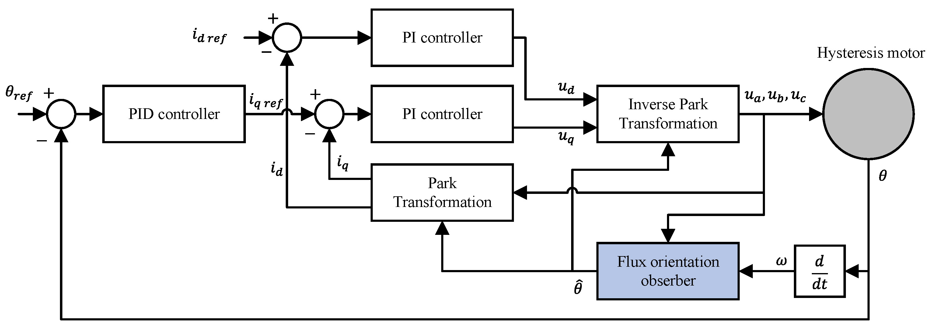
2.4.2. Dynamic Control Theory

Up to now, the general motor control method most commonly used has been vector control. Different from the PM motor, the magnetization state of the hysteresis rotor is affected by the stator magnetic field when the hysteresis motor works in the asynchronous state; the rotor flux direction should be oriented in the dynamic control process, which is a critical step in the hysteresis motor control.
Scholars from MIT established a control model based on magnetic field orientation [3,4]. Three methods for rotor flux orientation are given. The first is to directly use the rotor mechanical angle instead, which assumes that the magnetization state of the rotor is fixed, similar to the case of the permanent magnet synchronous motor. This method can be used at low speed without large error but not at high speed. Overexcitation can improve the accuracy of the method, as it will help to keep the rotor magnetization fixed on the d-axis. The second is to estimate the flux from the measured EMF because as the magnetized rotor rotates, a voltage is induced in the stator windings. This method is better at high speed because as the speed increases, EMF gradually increases, which is conducive to estimating the rotor flux. However, the magnetic saturation will lead to nonlinear changes in the rotor flux and inductance, affecting the estimation results. The third is to construct the Luenberger observer through the state-space model. This method has good accuracy in a wide speed range, and the experimental results are the best among the three methods. Its disadvantage is that properties of the rotor material must be known, so it is not suitable for commercial motors. And this method is very sensitive to the model parameters, which means the performance will significantly reduce when the parameter is inexact.
In the case that the motor parameters or material properties are unknown, an idea is to combine the first two methods, using method 1 at low speed and method 2 at high speed. However, it is difficult to define the boundary between low speed and high speed. For smooth switching, the following way can be used:
θ ^ = ( 1 S ( ω r ω r s w ) ) θ r + S ( ω r ω r s w ) ) θ ^ E M F
where ω r is the rotor speed, ω r s w is the speed threshold of the switching method, θ r is the rotor mechanical angle measured by the position sensor, θ ^ E M F is the flux angle estimated by EMF, and θ ^ is the synthetic rotor flux angle. The resultant function S ( x ) = 1 / ( 1 + e x ) is a smooth function that changes from 0 to 1.
On the basis of the rotor flux estimation, the control model can be constructed in the rotating dq coordinate as shown in Figure 13, and its main feature is the flux observer. The experimental results show that the control effect is satisfactory whether switching between method 1 and method 2, or using method 3 directly.
Scholars from Polytechnic University of Turin also studied the transient model and closed-loop control of the hysteresis motor by using the Luenberger observer, and gave a detailed Simulink diagram, showing the structure and description of each sub-system, which is easy to understand [58].
In the above control methods, the rotor position is needed because the variables related to the speed are involved in the observer’s state equation. Sensorless control can also be used for the hysteresis motor, where a model reference adaptive system (MRAS) is used to estimate the rotor speed [59,60].
For traditional hysteresis motors, the possible future works are as follows: (1) Improve its output torque through innovative structural design or new materials. (2) Seek a balance between the accuracy, rapidity and scalability of the calculation method by combining several calculation methods, or introducing the reduced-order model into the calculation of the hysteresis motor. (3) Apply the modern control technology, which is mature in the permanent magnet motors and induction motors to the hysteresis motor, to improve the accuracy of the magnetic field orientation, the control stability and response speed. (4) Explore more application scenarios requiring the unique advantages of hysteresis motors to promote its development.

3. Permanent Magnet Hysteresis Motor

Different from the traditional hysteresis motor, the permanent magnet hysteresis motor (PMHM) has hysteresis torque and permanent magnet torque at the same time because there are several permanent magnets (PMs) in its rotor. The common design is obtained just by replacing the material of the rotor core in the PM motor with hysteresis material, and the purpose is to give a self-starting ability to the PM motor. During the starting process, the constant magnetic field of the permanent magnet produces the braking torque, which increases the complexity of the analysis. Therefore, the key problem of the PMHM is the dynamic model.

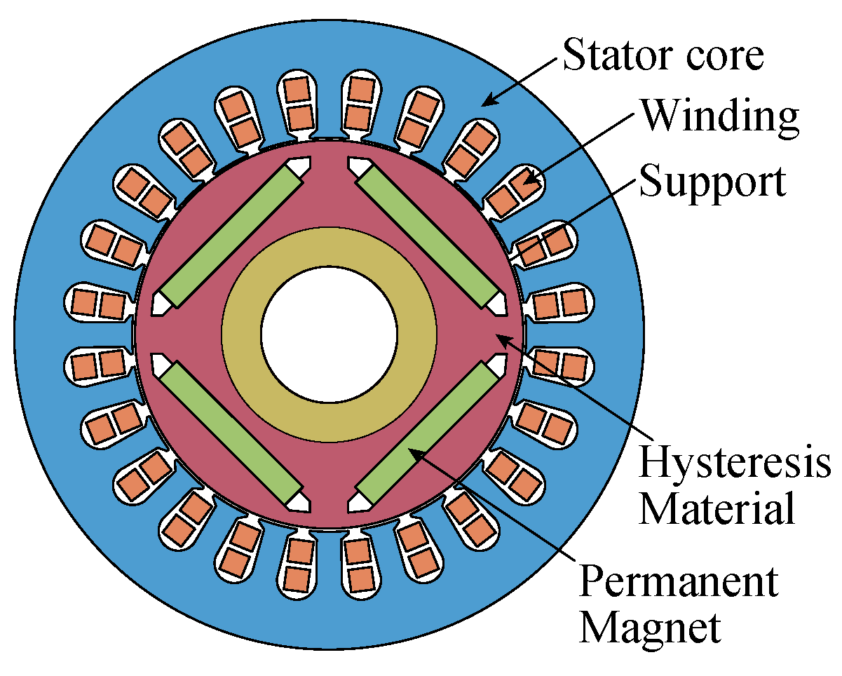
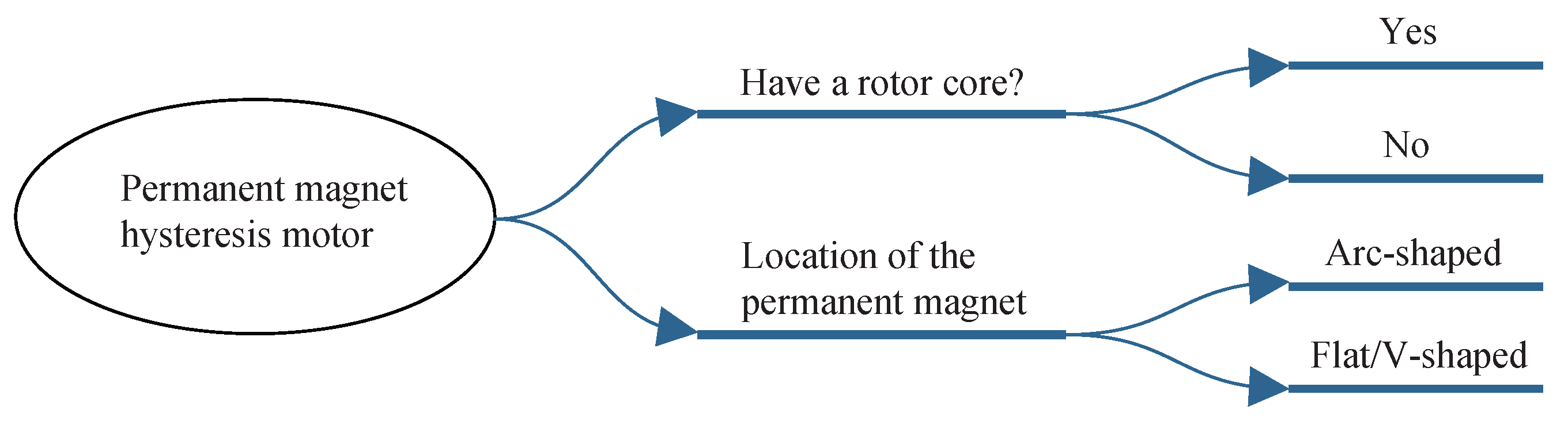
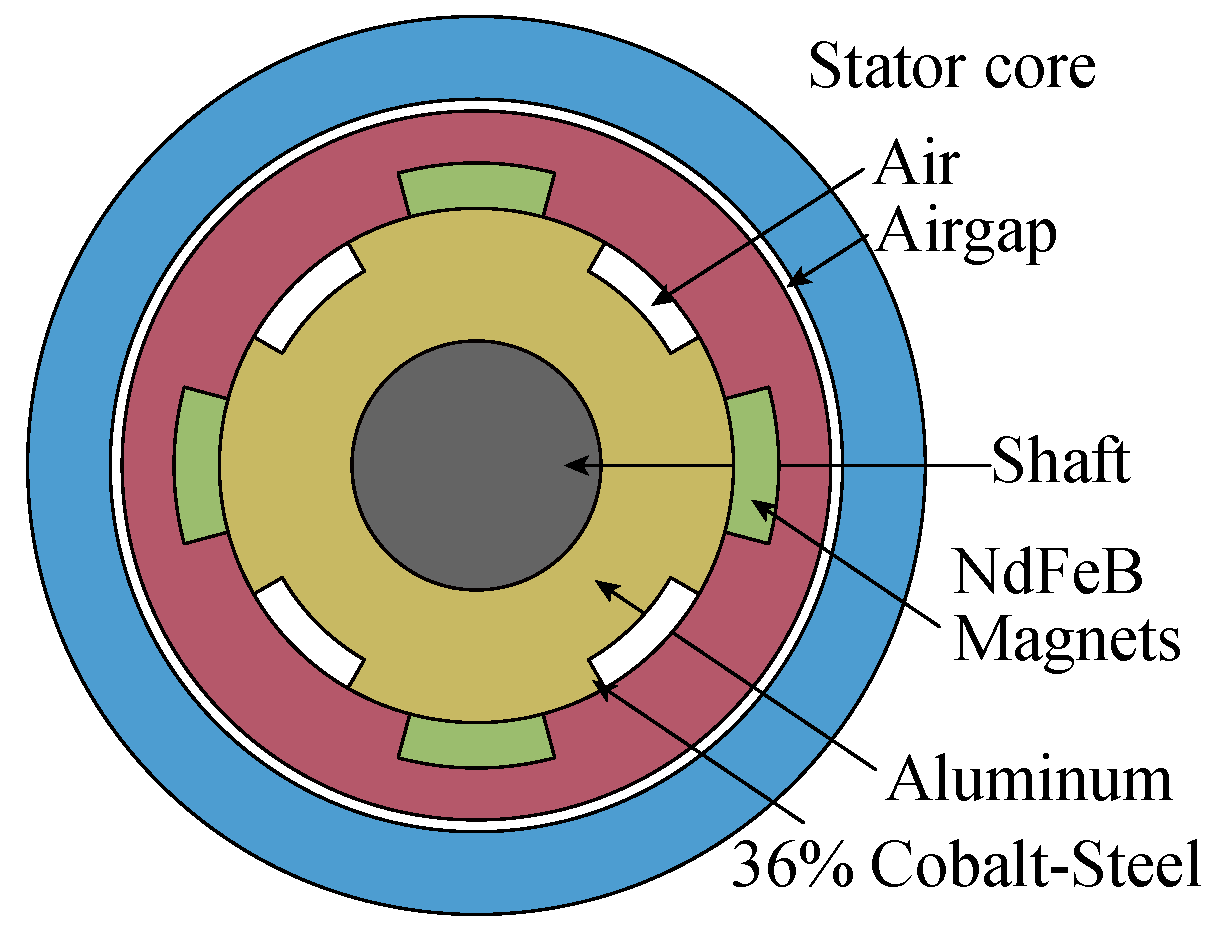
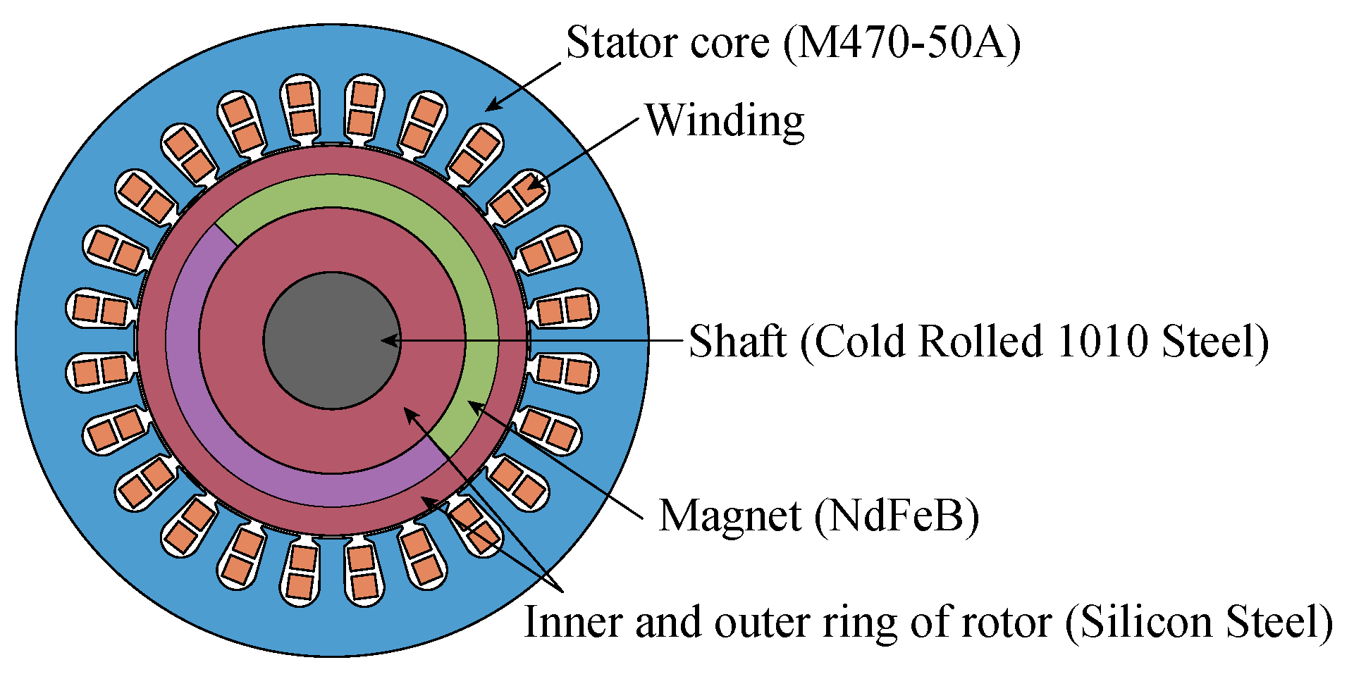
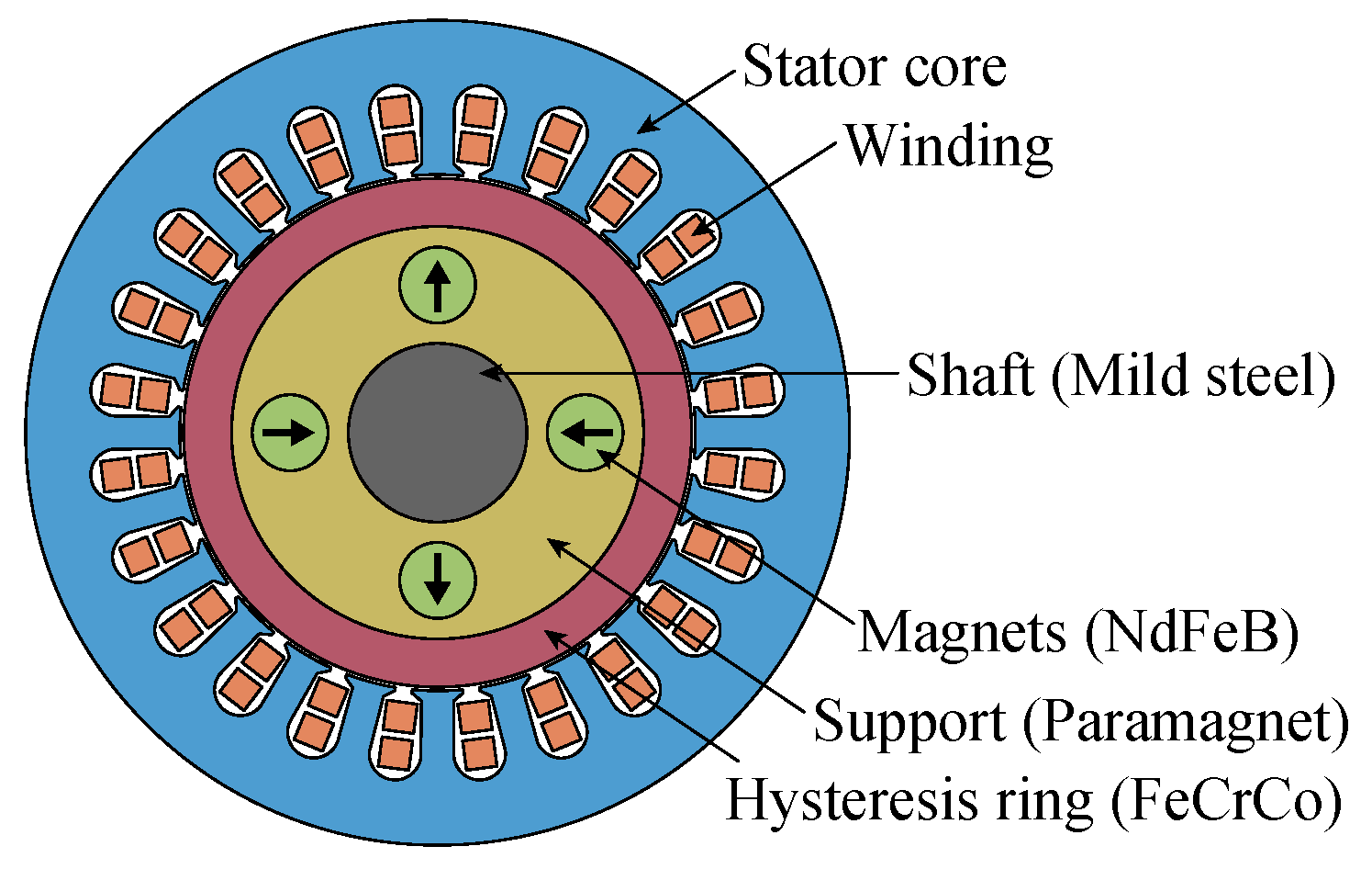
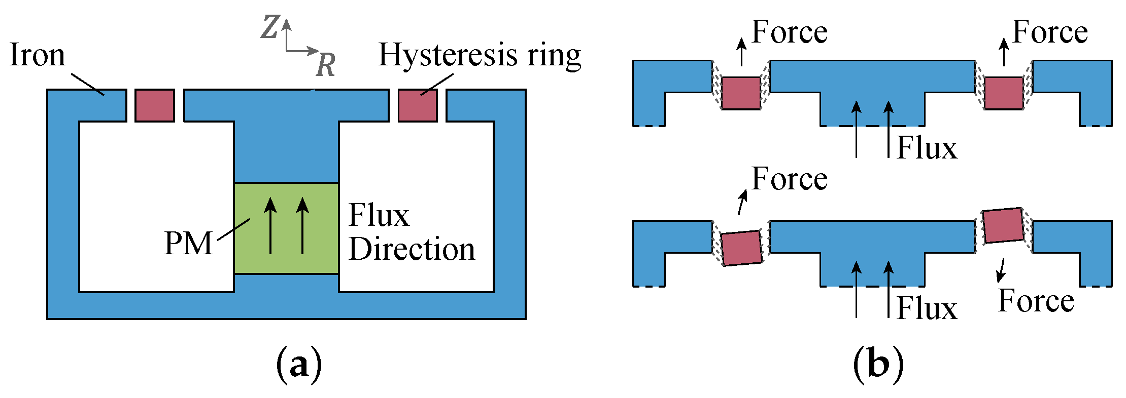
3.1. Structure and Classification
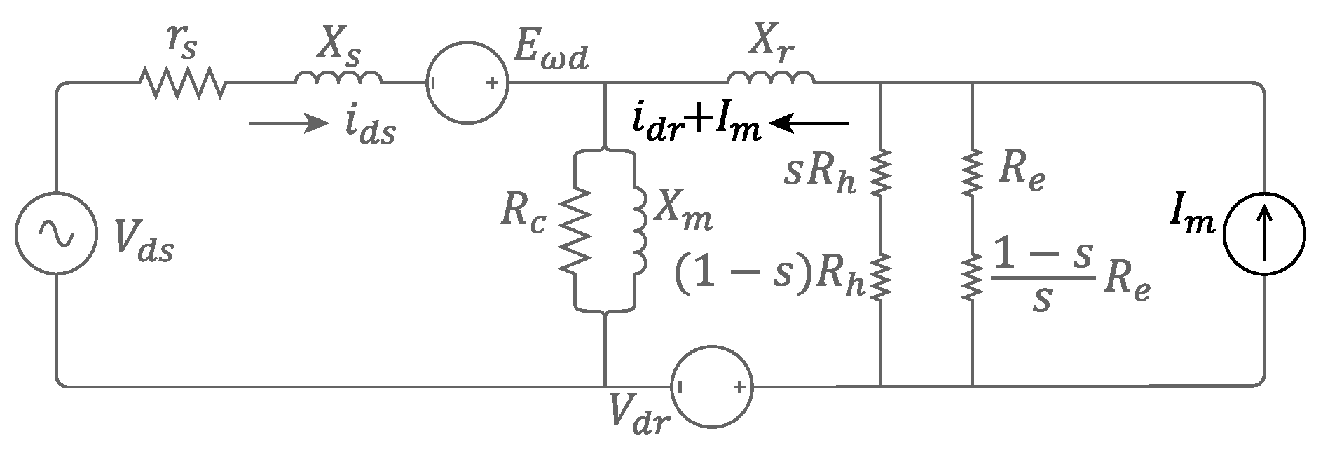
Similar to the hysteresis motor, the support inside the hysteresis ring in the PMHM can also be ferromagnetic or nonmagnetic, that is, with or without a rotor core. The difference is that the direction of the airgap flux of the PMHM is mostly radial. As shown in Figure 14, the PMs in the PMHM can be arc-shaped, flat and V-shaped.
Different from PM motor, the PMs in PMHM are hardly surface mounted as shown in Figure 15a but interior in the core as shown in Figure 15b. This is because, for PM motors, the interior structure will increase the flux leakage and reduce the synchronous output torque. And for PMHM, the surface-mounted structure will make the magnetic field in the hysteresis ring mainly be determined by the permanent magnet and difficult to be affected by the stator current, thus reducing the starting torque. The permeability of the hysteresis material is not as high as that of the silicon steel, so the flux leakage is not as obvious as for the permanent magnet motor.
As shown in Figure 16, a PMHM structure with an air cavity was proposed from the needs of electric vehicles [16]. Compared with the traditional permanent magnet motor or hysteresis motor, this combination has obvious advantages for self-starting and smooth operation. The finite element analysis shows that compared with 36% cobalt steel, the loop area of 17% cobalt steel is smaller, and the motor made is slightly slower to start. The structure without a permanent magnet added starts more smoothly and faster, but the torque output is insufficient [61]. Equivalent current and control models are seen in [62].
A PMHM with arc-shaped interior PMs was designed for an electric submersible pump (ESP) used in downhole operations in offshore and onshore oil fields [11,12]. The induction motor used in the past has the problems of poor power quality, poor thermal stability and low efficiency. The vibration caused by mechanical stress during starting often leads to motor failure and shaft failure. It is very inconvenient and costly to replace motor parts under the sea. Similar to the induction motor, PMHM has a self-starting ability and can work without a position sensor. In addition, PMHM has higher efficiency, higher reliability, simpler manufacturing and lower cost [63], so it can meet the requirements of ESP. The finite element and experimental results confirm the design correctness and self-starting ability of the motor [64].
As shown in Figure 17, a structure is designed for pump applications [10], whose PMs are between the inner and outer layers of the hysteresis material. Simulated and experimental results show that the volume is reduced by half, and the operating noise is lower, while its performance is on par with the induction motor.
For pump applications in [10], the stator/rotor lengths of the induction motor are about 170 mm, while the lamination length of the PMHM is only 70 mm. The cost of the PMHM is USD 160, less than that of the induction motor, USD 175. During work, the speed of the induction motor is 2810 rpm, while the speed of the PMHM is 3000 rpm, that is, the synchronous speed. The efficiency of PMHM is 79%, which is higher than that of the induction motor at 72%. The power factor of PMHM is 0.86, which is higher than that of the induction motor at 0.73. The torque ripple of PMHM is 16%, which is lower than that of the induction motor at 20%. The static head of PMHM is 55 m, which is higher than that of the induction motor at 50 m. From the above data, PMHM has comprehensive advantages over the induction motor. However, the starting speed of the PMHM needs to be improved. The performance of the two in other scenarios needs to be compared.
For the interior structure, the PM shape could also be flat (Figure 5) or V-shaped (Figure 18). The analysis and experiment [65,66] show that in the case of the same amount of the permanent magnet, the V-shaped structure allows more magnetic flux to be concentrated in the airgap, which can reduce the flux leakage and improve the output torque. In other words, in the case of the same output, the V-shaped structure can reduce the amount of permanent magnet. In addition, the V-shaped structure can have a more flexible adjustment so as to obtain more choices in the airgap magnetic field waveform, torque fluctuation, rotor stress and so on.
In the above structures, the hysteresis ring is mounted on a non-magnetic support (usually aluminum), forcing the magnetic flux in the hysteresis ring mainly along the circumference, which is called the circumferential flux motor. And the structure, by just replacing the support body with a laminated silicon steel, is the radial flux motor [66]. Comparison shows that the radial flux structure has higher starting torque and synchronous torque than circumferential flux motors with a similar structure. Therefore, radial flux motors have higher efficiency and power factor [67].
In addition, there is another structure which adds a sleeve made of hysteresis material outside the rotor of the permanent magnet motor to form a permanent magnet hysteresis motor [68] as shown in the Figure 19. Compared with the above structures, the advantage is that the hysteresis ring acts as a sleeve so that the motor can easily run at high speed. This motor has a torque greater than 0.2 Nm and is able to run at a synchronous speed of 50,000 rpm. Design optimization and prototype experiments have also been conducted.

3.2. Dynamic Model

Since the PMHM is designed to give the self-starting ability to the PM motor, it is important to study the change of current, torque and speed during its starting process, which relies on the dynamic model of the motor. Both the equivalent circuit method and finite element method could work. The former has fast calculation, while the latter is more accurate with slow speed.
For the permanent magnet hysteresis motor, its dynamic equivalent circuit is similar to that of the hysteresis motor, but the d-axis and q-axis circuits are no longer the same due to the addition of PM. In the d-axis equivalent circuit, the PM, as a magneto-motive force source, can be represented as an external constant current source I m as shown in Figure 20. And the equivalent circuit of q-axis is still as shown in Figure 12. I q s E ω q I d s E ω d is the output power by PM, whose average is zero in asynchronization because the direction of I d s and I q s is alternating, and only in synchronization there is a stable output power by PM. Combined with the mechanical transient equation, the dynamic response process of the motor can be calculated.
The starting and other dynamic processes of PMHM can also be simulated by the finite element model, which could be compared with the calculated and experimental results. Mainly positioned in industrial occasions, PMHM usually operates in a sensorless state, so its control model is not researched much. As for the closed-loop control, see [62,69].
For permanent magnet hysteresis motors, the possible future works are as follows: (1) Analyze the influence of permanent magnet shape and position on the motor performance. (2) Explore the combination of permanent magnet materials and hysteresis materials with different hardness. (3) Apply the multi-objective optimization method and topology optimization technology to explore more possibilities, and seek a balance between the starting torque and synchronous torque. (4) Make a more comprehensive comparison between the permanent magnet hysteresis motor, induction motor and squirrel-cage-assisted self-starting synchronous motor in different applications.

4. New Hysteresis Motor

Unlike the various types of hysteresis motors described earlier, there are also some innovative hysteresis motors with new structures. Related research still needs to be conducted in depth, which means that they have great potential for exploration.

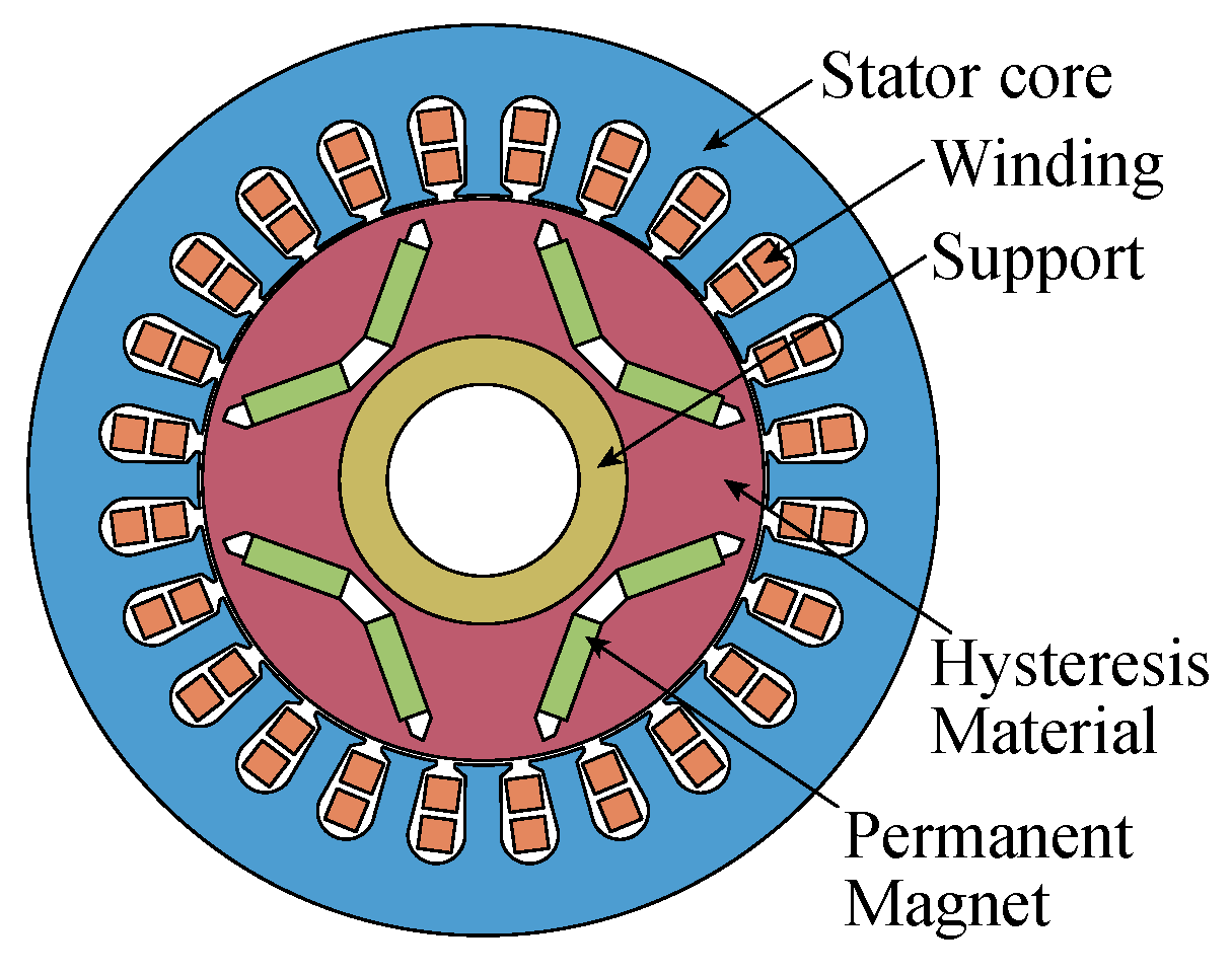
4.1. Hybrid Magnetic Flux

In order to improve the self-starting torque, output torque and efficiency, and to improve space utilization, the rotors of AFHM and RFHM can be hybridized to make more full use of the stator magnetomotive force [19]. This structure is evolved from the single-sided axial flux hysteresis motor (AFHM) in Figure 21a. A hysteresis ring is added to the inside of the stator, that is, to form the hybrid flux hysteresis motor (HFHM) as shown in Figure 21b, which can utilize both the axial and radial components of the flux, making both arms of the coil useful. From the torque theory, the torque of the hysteresis motor is proportional to the volume of the hysteresis material, and the hybrid structure increases the effective volume of the hysteresis material, so a larger output torque can be obtained.
For the hybrid structure, it is necessary to make the stator core have isotropic magnetism, and have uniform magnetic characteristics in both axial and radial directions to form a flux path in both directions. There are two types of materials with such properties. The first type is soft magnetic composite material, which can be regarded as ferromagnetic powder particles surrounded by electrical insulating film. The second type is soft ferrite, which is a ceramic compound formed by the chemical combination of iron oxide with one or more additional metal oxides (such as MnO). Soft ferrites are relatively cheap and have high permeability, so soft magnetic ferrites (Mn-Zn) are chosen in the paper. At the same time, because the conductivity of Mn-Zn ferrite is much lower than that of the steel material, it will not produce a large core loss, even at high frequency, so the motor can achieve higher efficiency.
Subsequently, the author proposes a motor structure with a hybridization of radial external rotor and axial rotor, called the reverse hybrid flux hysteresis motor (RHFHM) [70] as shown in Figure 22. In the case of the same volume, compared with HFHM, this structure increases the effective volume of the radial rotor, thus improving the torque current ratio, and also improving the motor efficiency. The structure is separated into axial and radial planes, and the performance of the motor is calculated by using the hyperbolic approximation model of the hysteresis loop, considering the 2D Cartesian coordinate system and the cylindrical coordinate system, respectively.
Although the above structures are theoretically feasible, the manufacturing is too complex to be suitable for industrial applications. In addition, the 3D magnetic field distribution, parasitic loss and so on have not been accurately described. Therefore, possible improvements lie in more detailed analysis and structure simplification.

4.2. Combined Torque Type

Another new structure is to combine the hysteresis motor with other types of motor, and the main goal is to improve the output torque of the hysteresis motor, including the combination of the hysteresis motor and reluctance motor, as well as the combination of the hysteresis motor and permanent magnet motor. Different from the aforementioned RHM and PMHM, their torque combination does not affect the respective magnetic fluxes but are almost independent of each other.
Replacing a disk of the double-sided rotor axial flux hysteresis motor with a reluctance disk, as shown in Figure 23a, can improve the output torque so as to improve motor efficiency and avoid hunting [71]. In this structure, the stator core is slotless because the slots will lead to fluctuations of flux density in the airgap, thereby increasing parasitic losses and reducing the efficiency of the motor. However, the starting of this structure is slower than that with a double-sided hysteresis motor because the hysteresis torque component is reduced, and the reluctance torque will increase the torque fluctuation in asynchronization. In applications requiring higher operating efficiency, the disadvantages of a long starting time can be accepted.
Similarly, there is a combination of the hysteresis motor and PM motor, that is, a hysteresis disk and a surface-mounted PM rotor [72,73], as shown in Figure 23b. The motor does not have the asymmetry of the d-axis and q-axis reluctance because of the surface-mounted structure, which reduces the torque fluctuation and motor noise. As a result, the motor is ideal for high-speed and high-power applications, such as high-power centrifuges. For the combined structure, the stator magnetomotive force of each phase is equal to the sum of that in the two airgaps, and its equivalent circuit can be combined in series by that of the hysteresis motor and the permanent magnet motor. The structure makes the permanent magnet motor and the hysteresis motor complement each other, and the experimental results confirm the validity of the design.
There is also a structure of segmented combination on the radial motor [74], which can also synthesize the performance of the permanent magnet motor and the hysteresis motor. The influence of different permanent magnet arrangements on the performance of the motor is analyzed.
The common feature of these new combined structures is a performance trade-off between several different types of motors. However, these structures are not fundamentally innovative, and some inherent advantages of hysteresis motors are destroyed. What is more, the possible application scenarios and the practicability are not clear, the advantages need to be further explored, and detailed designing and optimization need to be carried out.

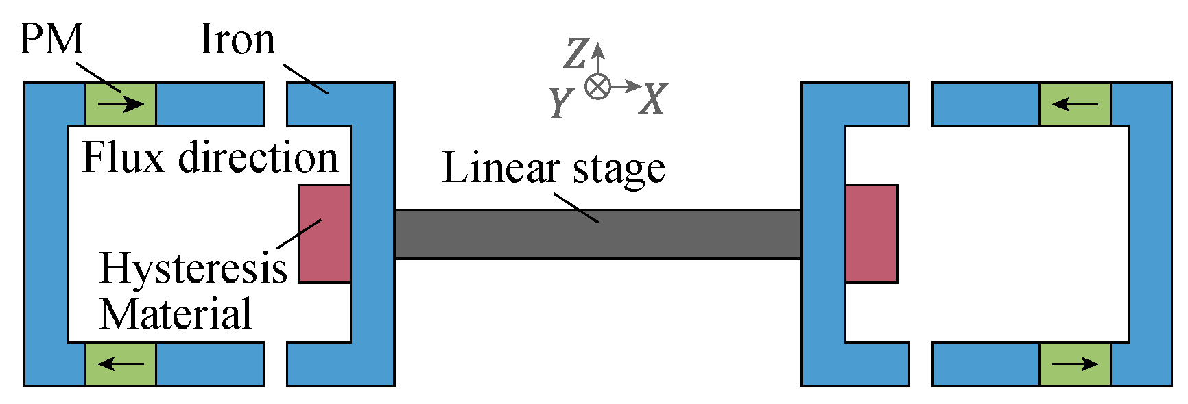
4.3. Bearingless Type

Bearingless motors are especially useful in pump applications, such as blood pumps or high-purity chemical experiments, which require contactless and pollution-free operation. The bearingless design can further expand the advantages of a simple structure, low noise and cleanliness. In [7], a bearingless slice hysteresis motor is designed. The suspension force is generated by the radial flux through the rotor from a unipolar permanent magnet, which is similar to the flux-biased magnetic bearings as shown in the Figure 24a, and both vertical deflection and rotation (including pitch and roll) can be passively balanced as shown in Figure 24b. The torque is generated by a 6-pole rotating magnetic field on the stator, which will not interfere with the suspension force. The two are decoupled. The control of suspension and rotation does not require angle sensors and commutation, which is conducive to reducing the cost of the whole system. Compared with other permanent magnet motors used for blood pumps, the torque output of the motor is insufficient, at only 2.67 mNm, but the stiffness and maximum speed are comparable to the prior technology, and the advantage is that the output torque of the hysteresis motor is smooth and stable.
The prototype experiment confirm the feasibility, but the control stability and mechanical structure design need to be further studied. If it is applied to the blood pump, the setting of the blood circulation path, the configuration of working mode and the installation of medical scene are still problems that need to be solved.
Similarly, for vacuum transportation in precision manufacturing systems, such as the lithography machines, hysteresis motors also show significant advantages in terms of smoothness and cleanliness. The magnetic levitation technology avoids the risk of contamination from mechanical contact. In [26], a linear bearingless slice hysteresis motor is designed for the linear transport platform in vacuum. Although it is different from the above blood pump motor in structure, its suspension principle is just similar as shown in Figure 25. The magnetic flux in the x direction enables the platform to passively levitate in the z direction, while the propulsion direction is in the y direction, and the platform’s deviation in the x direction is actively controlled. In this structure, a short secondary made of hysteresis material is used. The hysteresis effect makes the magnetization of the secondary lag behind the stator’s magnetic field in space, thus generating thrust. The secondary is usually pre-magnetized by a larger stator current pulse to improve the thrust generation ability.
Different from the rotary motor, there is an end effect in the linear motor, that is, the end of the secondary will be attracted by stator teeth due to the magnetic force, which will introduce a reluctance thrust and change the thrust characteristics of the hysteresis motor. For applying to the lithography machine, it still needs some improvement. The damping of passive suspension is relatively low, and additional dampers should be considered. The displacement sensor and magnetic encoder in the vacuum environment need to be improved.
There is a special structure in the bearingless hysteresis motors, that is, the spherical hysteresis motor, which can be used for attitude control of the spacecraft. In the flight control of the spacecraft, the rotation action requires an external torque, which is usually provided by the reaction wheel. In order to achieve attitude control with all degrees of freedom, at least three reaction wheels are usually required in the system. A magnetically suspended reaction sphere (MSRS) can be used as an alternative to reaction wheels for spacecraft attitude control, which allows independent acceleration on any axis by controlling a 3D spherical motor. Without the gyroscopic coupling of multiple reaction wheels with fixed rotating axes, all the attitude of the spacecraft can be controlled by a single device. In addition, the rotor is suspended in all directions, and magnetic levitation eliminates mechanical friction, which can extend the life of the equipment.
In [15], a preliminary study of 1D-MSRS motor is conducted. The 1D-MSRS consists of three subsystems: (1) magnetic levitation system of single degree of freedom for vertical suspension of spheres; (2) bearingless motor systems for lateral suspension of spheres; and (3) hysteresis motor for driving the rotor to rotate around the vertical axis. In the design and analysis of 1D-MSRS, these three subsystems are considered decoupled, i.e., interactions between subsystems are treated as interference. In 1D-MSRS, the lateral suspension of the rotor is achieved by a bearingless motor, which has two sets of windings on one stator. By correctly configuring and controlling the current in these windings, the motor can generate radial forces for the lateral suspension and a rotating magnetic field to rotate the rotor.
Compared with the commercial reaction wheels of small satellites, spherical bearingless hysteresis motors are better balanced, can operate at higher speeds (up to 12,000 rpm in the presence of air resistance) and consume less power in stable operation but have a lower output torque capacity.
The bearingless hysteresis motors are innovative and have great potential for special occasions. However, the analysis for them is not enough, and there is still a lot of work to be conducted in material selection, electromagnetic structure optimization, cooling structure design and so on. In addition, the control of this kind of motor is also a problem. The decoupling model and the control method with high precision, high stability and fast response need to be further studied.

5. Research on Key Issues

In this section, the hysteresis materials and hysteresis models are discussed. On the one hand, the hysteresis material of the rotor has a decisive influence on various types of hysteresis motors because the hysteresis torque is proportional to the area of the hysteresis loop. And because there are many types of hysteresis materials available, the comparison and the selection of the materials are quite important. On the other hand, the hysteresis phenomenon is the main principle of hysteresis motors, so the hysteresis model is crucial to accurately describe the hysteresis and calculate the motor performance. These material-related characteristics, models and methods are the premise of motor design and control.

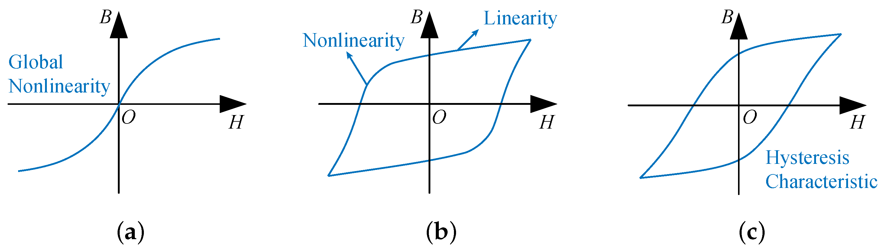
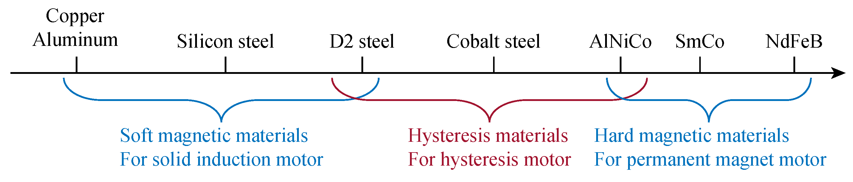
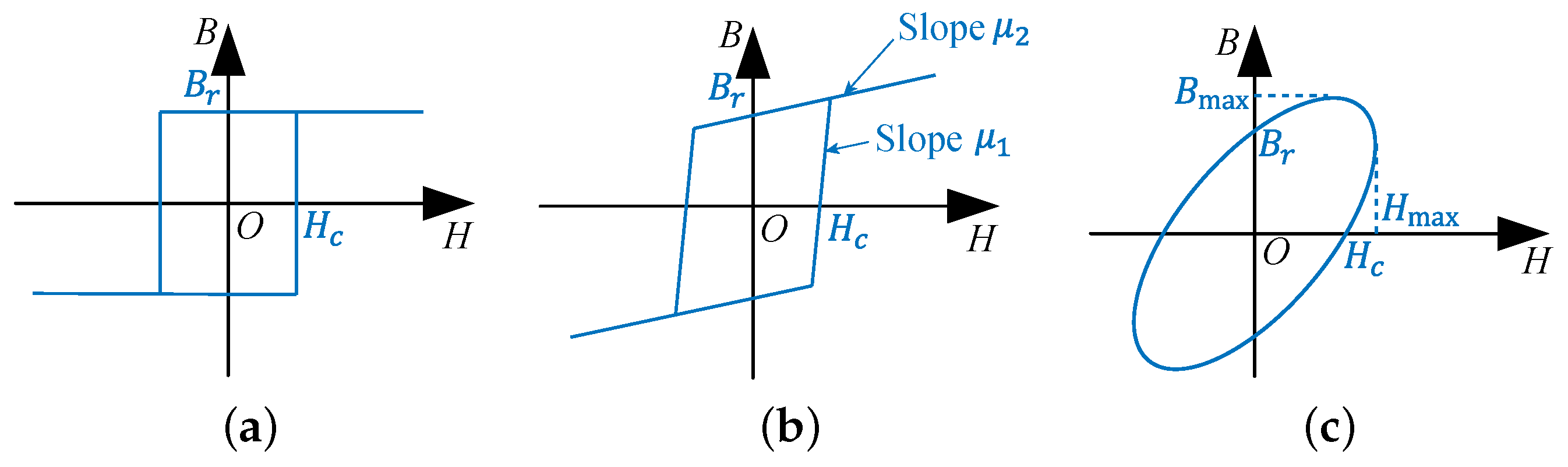
5.1. Hysteresis Materials

Hysteresis materials, also known as hysteresis alloys and semi-hard magnetic materials, refer to magnetic materials with coercive force between 800 A/m and 20 kA/m [75]. In fact, there is no strict boundary between soft magnetic materials, hard magnetic materials and semi-hard magnetic materials. Figure 26 shows the hardness order of common magnetic materials, and the material of the hysteresis motor rotor has a variety of choices, including tool steel, AlNiCo, FeCrCo, FeCoV and so on.
The properties of some typical hysteresis alloys can be found in [76,77]. And the Chinese standard for the hysteresis alloy and properties can be seen in [78], including FeCoNiV (2J4), FeCoV (2J7∼2J12), FeCoMo (2J21∼2J27) and FeMnNiMo (2J53).
The materials shown in the table may be semi-hard or permanent magnet materials. And it is more appropriate to distinguish them by whether they are driven by hysteresis loops in their operation or remain magnetized in a fixed direction.
Rotor materials have a crucial impact on the performance of hysteresis motors, such as the output torque, volume, loss and efficiency. The hysteresis torque is proportional to the area of the hysteresis loop, so the material with a wider hysteresis loop should be selected for torque enhancement. To be specific, the material with a large hysteresis loop area under the same amplitude of flux density should be selected.
For two prototypes with very similar geometric parameters, there are obvious performance differences due to the different hysteresis materials used. In [2], the motor with 36% cobalt steel has a larger output torque than that with 3% chrome steel at the same current; that for 36% cobalt steel has a larger hysteresis loop at the same flux density amplitude.
However, materials with wider hysteresis loops have lower permeability, greater parasitic losses, and, in addition, require a larger magnetizing current, resulting in a lower power factor [79].
In addition, the strength and temperature resistance of hysteresis materials should be taken into account. High mechanical strength and high temperature resistance are excellent characteristics of hysteresis alloys, which allow hysteresis motors to operate at high speed and to be used in some harsh environments. With turbochargers as the application background, scholars from Polytechnic University of Turin compared the ultimate tensile strength and maximum operating temperature of a variety of hysteresis alloys with permanent magnet materials [9]. The tensile strength of hysteresis materials is much higher than PMs, such as NdFeB and SmCo. And the working temperature of hysteresis materials can be 400∼500 °C, which shows the application prospect of the hysteresis motor in high-speed and high-temperature scenarios.
Finally, for material selection, it is also necessary to consider its process complexity, plasticity and economy, which are rarely involved in common research works. In short, the applicability of the hysteresis materials in hysteresis motors needs to be determined according to specific application scenarios and needs. Many factors need to be considered comprehensively; usually, a compromise between torque density and efficiency is important for motor optimization.
In addition to the reasonable selection of hysteresis materials, it is also important to study the technological improvement on material properties. The heat-treatment temperature, cooling method, cutting process and grinding process may affect the properties of the hysteresis alloy, and the most suitable process conditions can be found through experiments [80,81,82]. Increasing or decreasing the element content in the alloy also helps improve the performance of the hysteresis alloy, for example, adding Cr and reducing V can improve the coercivity of 2J4 alloy [83]. Researchers from Baikov Institute of Metallurgy and Materials Science of the Russian [84,85,86,87,88] have contributed a lot to the improvement of the preparation process of a variety of hysteresis materials, including different heat-treatment conditions, and different element content, as well as the difference between the induction melting method and powder metallurgy method. By the cross combination of a variety of test conditions, the influence of process factors can be fully explored [89]. However, the team’s work only focused on FeCoCr alloys with different element contents, and the results of each study are not closely related to each other, lacking a uniform and universal conclusion.

5.2. Hysteresis Model

In the research and modeling of other motors, hysteresis effects are often ignored because using a single-valued BH curve is effectively enough for soft magnetic materials. However, the hysteresis effect is the mechanism on which the hysteresis motor generates torque, and the output torque is proportional to the area of the hysteresis loop. The influence of magnetic field harmonics and speed changes during dynamic operation on torque can also be explained by the changes of the material hysteresis loop. Therefore, the modeling of hysteresis itself is indispensable for the performance evaluation of the hysteresis motor. The multi-value and nonlinear characteristics of hysteresis loops undoubtedly increase the complexity of modeling, so the expression of hysteresis loops must be clarified. Most of the early studies use approximate methods, such as parallelogram approximation and ellipse approximation, which can express hysteresis characteristics but are not accurate enough. In recent years, many studies have modeled hysteresis based on relatively accurate and complex numerical methods, such as the Preisach model and Jiles–Atherton model. In fact, the hysteresis model is essentially a mathematical model, and besides electromagnetism, it has a wide range of applications in other disciplines, such as mechanics, materials science, biology, economics and social science [90].

5.2.1. Approximate Model

Due to the complexity of the hysteresis loop, the relationship between flux density B and magnetic field strength H cannot be described by a single mathematical equation. To simplify, various types of approximation methods have appeared to replace the irregular BH curve in the real case.
The rectangular approximation is the simplest form, as shown in Figure 27a, which only need two basic parameters, that is, coercivity H c and remanence B r , suitable for magnetic materials with a ratio of the remanence and saturation flux density greater than 0.8. Because of its lack of accuracy, it is almost never used in calculation, just as a theoretical model.
The parallelogram approximation model was first used by Copeland and Slemon, and needs four parameters, namely coercivity H c , remanence B r , unsaturated permeability μ 1 and saturated permeability μ 2 as shown in Figure 27b [29]. This model is relatively simple and can show the hysteresis characteristic of the flux density relative to the magnetic field in calculation, which is helpful for qualitative analysis of the motor. However, the model is piecewise linear; when it is necessary to consider the distribution of the magnetic field in space, there is a certain inconvenience in the piecewise calculation. In addition, even if the magnetic motive force is sinusoidal, the flux solved by the model will contain a large number of harmonics. Subsequently, this model has been adopted, modified and improved by some studies [91].
The elliptic approximation model is shown in Figure 27c. In this method, the waveforms of the magnetic field and flux density are approximated to sinusoidal functions, and the harmonic component is ignored, so the BH curve is elliptical. Let the magnetic field H = H m sin ω t and flux density B = B m sin ( ω t γ ) , respectively, then the material can be described by two parameters, that is, permeability μ = B m / H m and hysteresis angle γ . Permeability determines the angle of the ellipse’s major axis, and the hysteresis angle determines the slenderness ratio of the ellipse. The remanent and coercive in this model are not fixed but vary with the amplitude of the magnetic field. By letting the area of the ellipse be equal to the area of the real hysteresis loop obtained by the experiment, a fairly high precision can be achieved in the calculation of the steady-state torque.
This model is convenient for calculation and equivalent circuit construction because the field strength and flux density are continuous smooth functions, and the hysteresis characteristics can be converted into resistive components in equivalent circuits. Because of its simplicity and ease of use, it has been widely used, starting from Teare’s paper [2] and many subsequent studies [27,32,92].
The above approximate models can be used to estimate the performance of the motor in a steady state to some extent. However, the real magnetic field distribution cannot be obtained. In addition, the these models may be inaccurate when the flux path is complex. Despite some limitations, the approximate models provide a good starting point for hysteresis motor modeling.

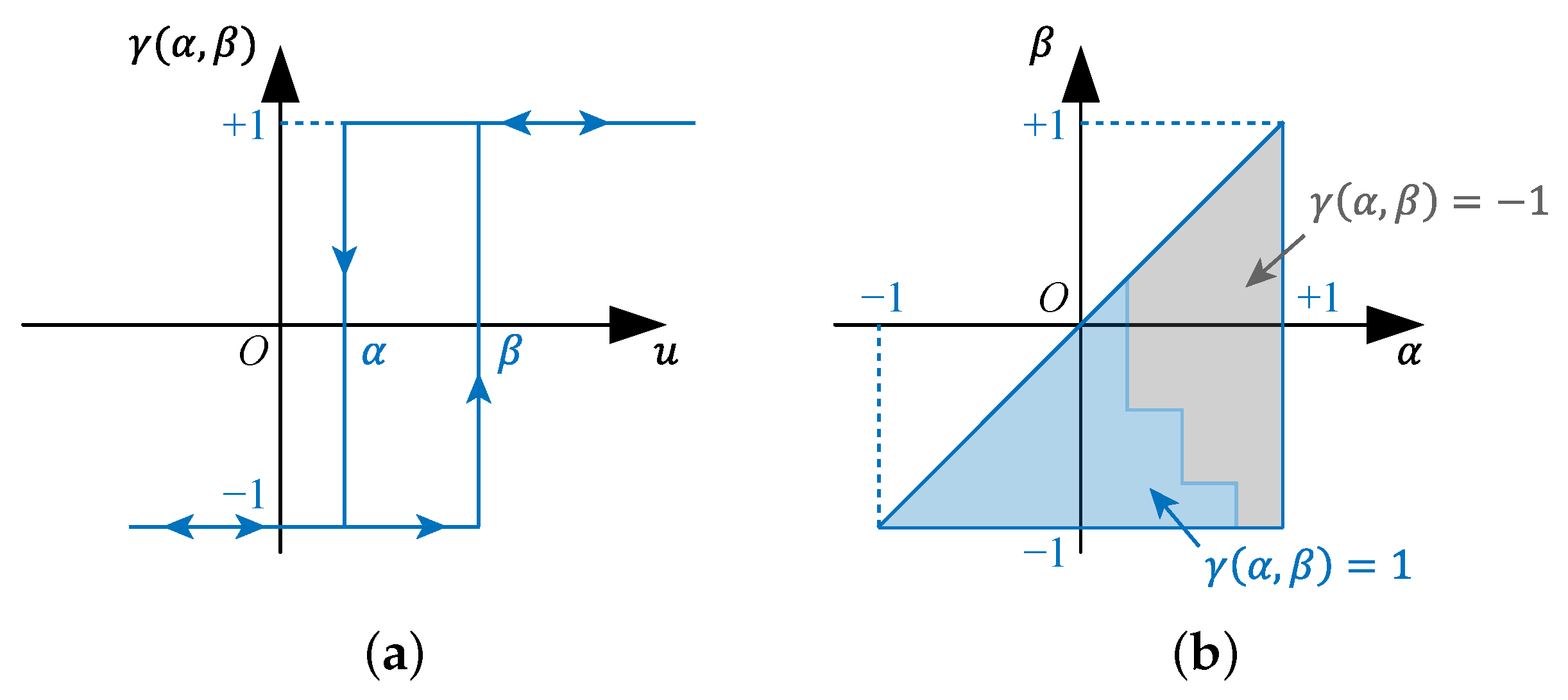
5.2.2. Preisach Model

As one of the earliest and most widely used hysteresis models, the Preisach model was proposed by Ferenc Preisach in 1935, but it was not widely used until 1988, when Mayergoyz’s classic work appeared [93,94], and the model was expanded in more detail in Mayergoyz’s book of 1991 [90]. In the Preisach model, the magnetized state of a material is represented by a large number of hysterons, each of which can be assumed to be a discrete state that is either positive or negative and has two thresholds for up and down as shown in Figure 28a. When a sufficiently large magnetic field is applied, some hysterons will flip their states, and the output of all hysterons is summed with weights to represent the flux density. This model can correspond to the points on a half plane, and the weight can be expressed by density function μ ( α , β ) , as shown in Figure 28b, so the output can be expressed as follows:
B ( t ) = α β μ ( α , β ) γ ( α , β ) H ( t ) d α d β
For the Preisach model, the most critical parameter is the weight μ , which is a function of α and β . It is complicated to determine its weight function. For engineers, it is not sufficient to model a material according to the data provided by the manufacturer or the general test results. For parameter identification, special experimental tests should be designed to obtain the reversal curves. In the classical Preisach model, the wiping out and congruency are necessary and sufficient conditions to represent the actual hysteresis. By modification, its scope of application can be extended. There are also studies on frequency dependence [95,96,97] and finite element integration [98,99] of the Preisach model.
At present, the Preisach model is not directly used for the hysteresis motor calculation but only used in the post-processing program to calculate the motor torque. That is, the flux density distribution in the hysteresis material is calculated using the basic magnetization curve and static simulation model, and then the hysteresis loop area at each position is calculated with the Preisach model [38,52]. This is because in the finite element model, the BH constitutive relation needs to be performed on each mesh grid at every moment, so the BH relation must be very simple.

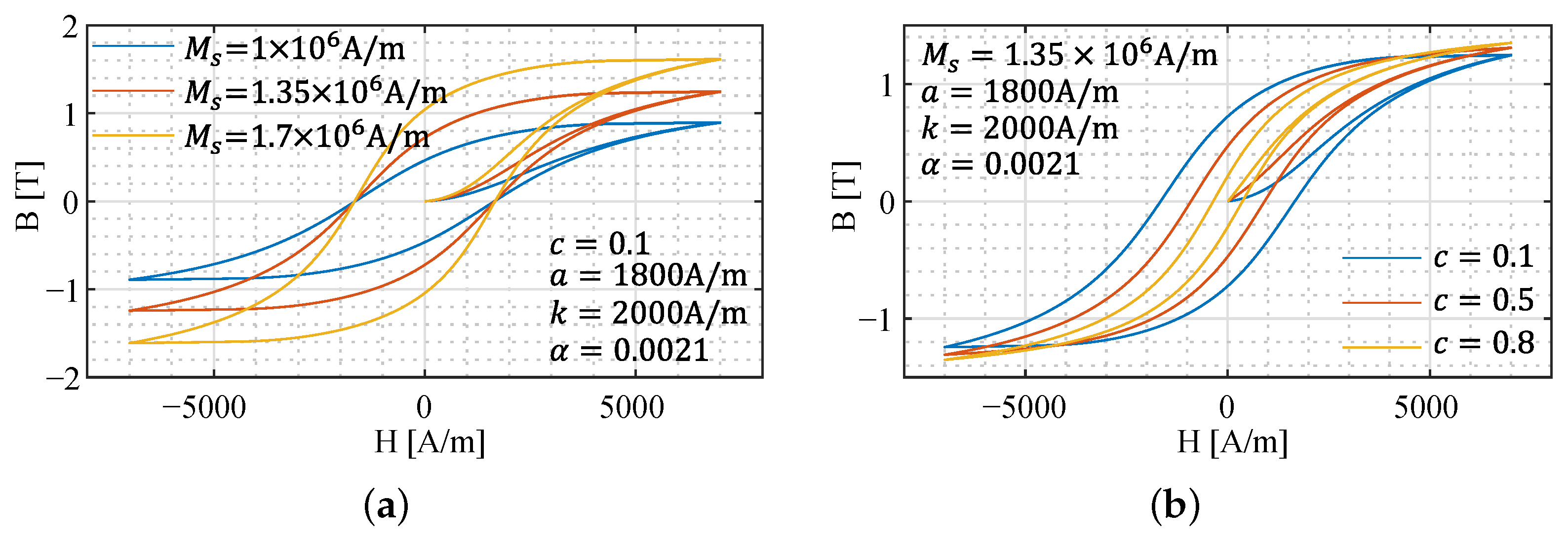
5.2.3. Jiles–Atherton Model

The Jiles–Atherton model (JA model) appeared in the early 1980s as a model specifically designed to describe the pinning and rotation of the domain in ferromagnetic materials, and is related to the physical mechanisms of magnetization dynamics [100]. The model was widely known after its introduction by SPICE, one of the most popular general-purpose analog electronic circuit simulators on the market. In SPICE, the Jiles–Atherton model can be used to simulate the magnetic cores of inductors, transformers and other components containing ferromagnetic materials. Jiles and Atherton’s original work contained many descriptions of magnetization theory in complex forms, and the model was later refined and simplified to be easier to understand, and the mathematical notation was modified to the form commonly used today [101].
The JA model has five parameters, they are saturation magnetization M s (A/m), domain wall density a (A/m), average energy to break pinning site k (A/m), magnetization reversibility c and interdomain coupling α . Figure 29 shows the calculation results of JA model, which means various hysteresis loops can be obtained by adjusting the parameters.
The non-hysteresis curve in the JA model is the Langevin function, and as long as it conforms to experimental data, other forms of functions can also be used as non-hysteresis curves [102], such as the Brioullin function, Erf function, etc. [103]. Different types of curves are suitable for materials with different internal structures (for example, polycrystalline, amorphous, nanomaterials, etc.), and the accuracy of the model on small loops can be further improved by selecting the appropriate form of the non-hysteresis function [104].
For the parameter identification of the JA model, the slope and intercept on the tested hysteresis loop can be used. In most cases, this method can successfully determine the value of the parameters, and the error is within a few percentage points [100,105]. Intelligent optimization algorithm can also be used to accomplish this work by setting the error minimization function [106,107]. There are also related studies on the frequency dependence [108,109,110] and temperature dependence [111] of the JA model.
The JA model can simulate the magnetization process of ferromagnetic materials well, has strong practicability and accuracy, and is suitable for hysteresis motor and other electromagnetic devices involving the hysteresis phenomenon. This model has only five parameters, and can be conveniently integrated in the finite element calculation. For example, COMSOL contains the hysteresis relationship based on the JA model [112], which could be used to analyze and design the hysteresis motor, including the magnetic field in the rotor, output torque and other performance results [41]. In [42,49], the JA model and finite element model are used to simulate the dynamic performance of the motor in the starting process. The problem of the JA model is that the shape of the hysteresis loop is very sensitive to the model parameters, which may produce larger errors over the course of use than when the parameters are fitted.
To sum up, approximate models can be used for preliminary estimation without high accuracy. Both the Preisach and JA models have good practicability and high accuracy. The JA model is supported by magnetic domain theory and has more concise parameters. In addition, the JA model has superiority over the Preisach model in parameter fitting [113]. However, the Preisach model is more accurate in dealing with small loops than the JA model [114]. In [115], the tests on various materials under sinusoidal and non-sinusoidal excitation are used to compare the accuracy of the JA model and Preisach model. The JA model is worse in accuracy than the Preisach model, especially for non-sinusoidal excitation because the small loops of the JA model cannot be completely closed, but the JA model is faster in computation and better in numerical realizability.
Moreover, the JA model is easier to be integrated with the finite element method. Therefore, the JA model has been used the most in recent studies. In addition, the Hauser energy model, Bouc–Wen model, Stoner–Wohlfarth model, Coleman–Hodgdon model, and Globus model have also been used to describe the hysteresis of materials. Due to the complexity and poor applicability, they are not widely used in hysteresis motors.

6. Conclusions and Future Directions

According to the different structures of the hysteresis motor, this paper introduces the characteristics, analysis methods and research statuses of the traditional hysteresis motor, permanent magnet hysteresis motor and new hysteresis motors. For the traditional hysteresis motor, the main advantages are high temperature resistance and high speed, and the research mainly focuses on the calculation of the magnetic field and output characteristics because their structural is relatively simple. For the permanent magnet hysteresis motor, the main advantages are high torque density and self-starting ability, and the key problem is the rapidity and stationarity of the starting process, so many studies are carried out for the dynamic model theory. For new hysteresis motors, including the flux hybridization type, torque combined type and bearingless type, the first two are mainly meant to increase the output torque of the hysteresis motor, and the bearingless type is mainly meant to improve cleanliness and reduce pollution. The new designs open up new directions for the development of the hysteresis motor, and the relevant theory still needs to be improved. Finally, two key issues affecting the performance of hysteresis motors are discussed, namely, hysteresis materials and the hysteresis model. With regard to hysteresis materials, it is necessary to clearly understand their electromagnetic, temperature and stress characteristics in order to select suitable materials in motor design. And different hysteresis models vary in complexity, calculation accuracy and calculation speed, so it is appropriate to choose a hysteresis model according to needs.
The future research of hysteresis motor is mainly concentrated in the following aspects:
  • Improve the output torque and efficiency of traditional hysteresis motor through the reasonable design of an electromagnetic structure and development of an innovative structure.
  • Combine the advantages of the traditional hysteresis motor and other motors to expand more application scenarios.
  • Develop a more accurate, fast and versatile analytical calculation program of the hysteresis motor, declare the coupling relationship between temperature rise, stress and electromagnetism.
  • Develop new hysteresis materials to improve electromagnetic properties, thermal stability and mechanical strength.
  • Apply the advanced control technologies to the hysteresis motor, and propose new control strategies suitable for the hysteresis motor to improve its control accuracy and stability.
  • Explore the application of the intelligent optimization method, reduced-order model technique and digital twin in the hysteresis motor to form interdisciplinary characteristics.
  • Explore the application of the hysteresis motor in more fields and scenarios, and show the potential brought by its unique advantages.
Besides the hysteresis motor, other applications related to hysteresis, such as hysteresis coupling [116,117], hysteresis break, hysteresis clutch, and electromagnetic actuators, are also worth studying. In addition, studying the influence of the hysteresis effect in soft magnetic materials on transformers and large motors, and improving the accuracy of hysteresis loss calculation from the hysteresis model [118,119,120,121] are also important problems.

Author Contributions

Conceptualization, B.G. and Y.C.; investigation, B.G. and T.Z.; resources, Y.C. and S.C.; data curation, B.G.; writing—original draft preparation, B.G. and H.S.; writing—review and editing, B.G. and H.S.; visualization, B.G.; supervision, Y.C. and S.C.; project administration, T.Z.; funding acquisition, Y.C. and S.C. All authors have read and agreed to the published version of the manuscript.

Funding

This work is funded by the Fundamental Research Funds for the Central Universities No. FRFCU5710010719, and by the Key Research and Development Program of Heilongjiang Province No. JD22A002.

Data Availability Statement

Not applicable.

Conflicts of Interest

The authors declare no conflict of interest.

Abbreviations

The following abbreviations are used in this manuscript:
HMHysteresis motor (traditional)
PMPermanent magnet
PMHMPermanent magnet hysteresis motor
RHMReluctance hysteresis motor
RFHMRadial flux hysteresis motor
AFHMAxial flux hysteresis motor
MRASModel reference adaptive system
ESPElectric submersible pump
HFHMHybrid flux hysteresis motor
RHFHMReverse hybrid flux hysteresis motor
MSRSMagnetically suspended reaction sphere
JAJiles–Atherton

References

  1. Steinmetz, C.P. On the Law of Hysteresis (Part II.) and Other Phenomena of the Magnetic Circuit. Trans. Am. Inst. Electr. Eng. 1892, 9, 619–758. [Google Scholar] [CrossRef]
  2. Teare, B.R. Theory of hysteresis-motor torque. Electr. Eng. 1940, 59, 907–912. [Google Scholar] [CrossRef]
  3. Zhou, L.; Gruber, W.; Trumper, D.L. Position Control for Hysteresis Motors: Transient-Time Model and Field-Oriented Control. IEEE Trans. Ind. Appl. 2018, 54, 3197–3207. [Google Scholar] [CrossRef]
  4. Zhou, L. Magnetically Levitated Hysteresis Motor Driven Linear Stage for In-Vacuum Transportation Tasks. Ph.D. Thesis, Massachusetts Institute of Technology, Cambridge, MA, USA, 2019. [Google Scholar]
  5. Wikipedia. Outgassing. Available online: https://en.wikipedia.org/wiki/Outgassing (accessed on 15 April 2023).
  6. NASA. Outgassing Data for Selecting Spacecraft Materials. Available online: https://outgassing.nasa.gov/ (accessed on 15 April 2023).
  7. Noh, M.; Gruber, W.; Trumper, D.L. Hysteresis Bearingless Slice Motors with Homopolar Flux-Biasing. IEEE/ASME Trans. Mechatron. 2017, 22, 2308–2318. [Google Scholar] [CrossRef] [Green Version]
  8. Zhang, Y.; Yan, X.; Zhang, Z. With the electrical properties of a new turbocharger. In Proceedings of the 2010 International Conference on Mechanic Automation and Control Engineering, Wuhan, China, 26–28 June 2010; pp. 3465–3468. [Google Scholar] [CrossRef]
  9. Galluzzi, R.; Tonoli, A.; Amati, N. Magnetic hysteresis machines for next-generation electric turbochargers. In Proceedings of the 2017 International Conference of Electrical and Electronic Technologies for Automotive, Torino, Italy, 15–16 June 2017; pp. 1–5. [Google Scholar] [CrossRef]
  10. Gedıkpinar, M. Design and Implementation of a Self-Starting Permanent Magnet Hysteresis Synchronous Motor for Pump Applications. IEEE Access. 2019, 7, 186211–186216. [Google Scholar] [CrossRef]
  11. Rabbi, S.F.; Rahman, M.A. Equivalent Circuit Modeling of a Hysteresis Interior Permanent Magnet Motor for Electric Submersible Pumps. IEEE Trans. Magn. 2016, 52, 8104304. [Google Scholar] [CrossRef]
  12. Rabbi, S.F.; Rahman, M.A.; Sarker, M.M.; Butt, S.D. Modeling and performance evaluation of a hysteresis IPM motor drive for electric submersible pumps. In Proceedings of the 2015 IEEE Energy Conversion Congress and Exposition (ECCE), Montreal, QC, Canada, 20–24 September 2015; pp. 4105–4112. [Google Scholar] [CrossRef]
  13. Chalmers, B.J.; Ciric, I.R. Performance Analysis of Hysteresis-Reluctance Motors with Segmental Rotors. Proc. IEE. 1974, 121, 991. [Google Scholar] [CrossRef] [Green Version]
  14. Rahman, M.A.; Osheiba, A.M. Steady-State Performance Analysis of Polyphase Hysteresis-Reluctance Motors. IEEE Trans. Ind. Appl. 1985, IA-21, 659–663. [Google Scholar] [CrossRef]
  15. Zhou, L.; Imani Nejad, M.; Trumper, D.L. One-axis hysteresis motor driven magnetically suspended reaction sphere. Mechatronics 2017, 42, 69–80. [Google Scholar] [CrossRef]
  16. Rahman, M.; Qin, R. A permanent magnet hysteresis hybrid synchronous motor for electric vehicles. IEEE Trans. Ind. Electron. 1997, 44, 46–53. [Google Scholar] [CrossRef]
  17. Benfu, M. Design of Hysteresis Motor for Liquid Float Gyroscope. Master’s Thesis, Tianjin University, Tianjin, China, 2017. [Google Scholar]
  18. Darabi, A.; Lesani, H.; Ghanbari, T.; Akhavanhejazi, A. Modeling and optimum design of disk-type hysteresis motors. In Proceedings of the 2007 International Conference on Electrical Machines and Systems (ICEMS), Sydney, Australia, 11–14 August 2007; pp. 998–1002. [Google Scholar] [CrossRef]
  19. Nasiri-Zarandi, R.; Mirsalim, M.; Tenconi, A. A Novel Hybrid Hysteresis Motor With Combined Radial and Axial Flux Rotors. IEEE Trans. Ind. Electron. 2016, 63, 1684–1693. [Google Scholar] [CrossRef]
  20. Rayleigh, L. XXI. Notes on magnetism.—I. On the energy of magnetized iron. Lond. Edinb. Dublin Philos. Mag. J. Sci. 1886, 22, 175–183. [Google Scholar] [CrossRef]
  21. Steinmetz, C.P. Theory and Calculation of Alternating Current Phenomena; Kessinger Publishing: Whitefish, MT, USA, 2008. [Google Scholar]
  22. Steinmetz, C.P. Theory and Calculations of Electrical Apparatus; McGraw-Hill Book Company: New York, NY, USA, 1917. [Google Scholar]
  23. Livens, G.H. The Theory of Electricity. Nature 1927, 119, 385. [Google Scholar] [CrossRef]
  24. Holmes, W.; Grundy, E. Small self-starting synchronous time motors. J. Inst. Electr. Eng. 1935, 77, 379–399. [Google Scholar] [CrossRef]
  25. Giulii Capponi, F.; De Donato, G.; Caricchi, F. Recent Advances in Axial-Flux Permanent-Magnet Machine Technology. IEEE Trans. Ind. Appl. 2012, 48, 2190–2205. [Google Scholar] [CrossRef]
  26. Zhou, L.; Trumper, D.L. Magnetically Levitated Linear Stage With Linear Bearingless Slice Hysteresis Motors. IEEE/ASME Trans. Mechatron. 2021, 26, 1084–1094. [Google Scholar] [CrossRef]
  27. Darabi, A.; Ghanbari, T.; Sanati Moghadam, M. Slotless axial flux hysteresis motor, modelling and performance calculation. IET Electr. Power Appl. 2009, 3, 491–501. [Google Scholar] [CrossRef]
  28. Darabi, A.; Sanati-Moghadam, M.; Ghanbari, T. Coreless Dual-rotor Disc Hysteresis Motor, Modeling, and Performance Prediction. Electr. Power Compon. Syst. 2010, 38, 575–591. [Google Scholar] [CrossRef]
  29. Copeland, M.A.; Slemon, G.R. An Analysis of the Hysteresis Motor I—Analysis of the Idealized Machine. IEEE Trans. Power Appar. Syst. 1963, 82, 34–42. [Google Scholar] [CrossRef]
  30. Copeland, M.A.; Slemon, G.R. An Analysis of the Hysteresis Motor II-The Circumferential-Flux Machine. IEEE Trans. Power Appar. Syst. 1964, 83, 619–625. [Google Scholar] [CrossRef]
  31. Ghanbari, T.; Sanati Moghadam, M.; Darabi, A. Comparison between coreless and slotless kinds of dual rotor discs hysteresis motors. IET Electr. Power Appl. 2016, 10, 133–140. [Google Scholar] [CrossRef]
  32. Nitao, J.J.; Scharlemann, E.T.; Kirkendall, B. Equivalent Circuit Modeling of Hysteresis Motors; Lawrence Livermore National Lab.(LLNL): Livermore, CA, USA, 2009. [Google Scholar]
  33. Lubin, T.; Mezani, S.; Rezzoug, A. Exact Analytical Method for Magnetic Field Computation in the Air Gap of Cylindrical Electrical Machines Considering Slotting Effects. IEEE Trans. Magn. 2010, 46, 1092–1099. [Google Scholar] [CrossRef] [Green Version]
  34. Pfister, P.D.; Perriard, Y. Slotless Permanent-Magnet Machines: General Analytical Magnetic Field Calculation. IEEE Trans. Magn. 2011, 47, 1739–1752. [Google Scholar] [CrossRef]
  35. Nasiri-Zarandi, R.; Mirsalim, M. Analysis and Torque Calculation of an Axial Flux Hysteresis Motor Based on Hyperbolic Model of Hysteresis Loop in Cartesian Coordinates. IEEE Trans. Magn. 2015, 51, 8105710. [Google Scholar] [CrossRef]
  36. Repetto, M.; Uzunov, P. Analysis of Hysteresis Motor Starting Torque Using Finite Element Method and Scalar Static Hysteresis Model. IEEE Trans. Magn. 2013, 49, 2405–2408. [Google Scholar] [CrossRef]
  37. Kim, H.K.; Hong, S.K.; Jung, H.K. Analysis of hysteresis motor using finite element method and magnetization-dependent model. IEEE Trans. Magn. 2000, 36, 685–688. [Google Scholar] [CrossRef]
  38. Hong, S.K.; Kim, K.K.; Kim, H.S.; Jung, H.K. Torque calculation of hysteresis motor using vector hysteresis model. IEEE Trans. Magn. 2000, 36, 1932–1935. [Google Scholar] [CrossRef]
  39. Gallicchio, G.; Palmieri, M.; Di Nardo, M.; Cupertino, F. Fast Torque Computation of Hysteresis Motors and Clutches Using Magneto-static Finite Element Simulation. Energies 2019, 12, 3311. [Google Scholar] [CrossRef] [Green Version]
  40. Lee, H.Y.; Hahn, S.Y.; Park, G.S.; Lee, K.S. Torque computation of hysteresis motor using finite element analysis with asymmetric two dimensional magnetic permeability tensor. IEEE Trans. Magn. 1998, 34, 3032–3035. [Google Scholar] [CrossRef]
  41. Galluzzi, R.; Amati, N.; Tonoli, A. Modeling, Design, and Validation of Magnetic Hysteresis Motors. IEEE Trans. Ind. Electron. 2020, 67, 1171–1179. [Google Scholar] [CrossRef]
  42. Padilha, J.B.; Kuo-Peng, P.; Sadowski, N.; Batistela, N.J. Vector hysteresis model associated to FEM in a hysteresis motor modeling. In Proceedings of the 2016 IEEE Conference on Electromagnetic Field Computation (CEFC), Miami, FL, USA, 13–16 November 2016; p. 1. [Google Scholar] [CrossRef]
  43. Darabi, A.; Tahanian, H.; Amani, S.; Sedghi, M. An Experimental Comparison of Disc-Type Hysteresis Motors With Slotless Magnetic Stator Core. IEEE Trans. Ind. Electron. 2017, 64, 4642–4652. [Google Scholar] [CrossRef]
  44. Miyairi, T.K.S. A basic equivalent circuit of the hysteresis motor. J. Inst. Electr. Eng. Jpn. 1965, 85, 1740–1748. [Google Scholar]
  45. Darabi, A.; Ghanbari, T.; Rafiei, M.; Lesani, H.; Sanati-Moghadam, M. Dynamic Performance Analysis of Hysteresis Motors by a Linear Time-Varying Model. Iran. J. Electr. Electron. Eng. 2008, 4, 202–215. [Google Scholar]
  46. Modarres, M.; Kwon, B.I. Rotor design to improve dynamic performance of axial flux hysteresis motors. IET Electr. Power Appl. 2015, 9, 44–49. [Google Scholar] [CrossRef] [Green Version]
  47. Niasar, A.H.; Ghanbari, A.; PirZadeh, A. An improved analytical dynamic modeling of hysteresis motor. In Proceedings of the 2016 24th Iranian Conference on Electrical Engineering (ICEE), Shiraz, Iran, 10–12 May 2016; pp. 879–884. [Google Scholar] [CrossRef]
  48. Niasar, A.H. A novel time varying dynamic modeling for hysteresis motor. Sci. Iran. 2017, 24, 1395–1409. [Google Scholar]
  49. Rezaeealam, B. Finite-element/boundary-element transient modelling of hysteresis motors. J. Magn. Magn. Mater. 2021, 519, 167474. [Google Scholar] [CrossRef]
  50. Clurman, S. On hunting in hysteresis motors and new damping techniques. IEEE Trans. Magn. 1971, 7, 512–517. [Google Scholar] [CrossRef]
  51. Soroush, H.R.; Rahmati, A.; Moghbelli, H.; Vahedi, A.; Niasar, A.H. Study on the hunting in high speed hysteresis motors due to the rotor hysteresis material. In Proceedings of the IEEE EUROCON 2009, St. Petersburg, Russia, 18–23 May 2009; pp. 677–681. [Google Scholar] [CrossRef]
  52. Kim, H.S.; Hong, S.K.; Han, J.H.; Choi, D.J. Dynamic Modeling and Load Characteristics of Hysteresis Motor Using Preisach Model. In Proceedings of the 2018 21st International Conference on Electrical Machines and Systems (ICEMS), Jeju, Republic of Korea, 7–10 October 2018; pp. 560–563. [Google Scholar] [CrossRef]
  53. Roters, H.C. The hysteresis motor-advances whick permit economical fractional horsepower ratings. Trans. Am. Inst. Electr. Eng. 1947, 66, 1419–1430. [Google Scholar] [CrossRef]
  54. Kataoka, T.; Ishikawa, T.; Takahashi, T. Analysis of a hysteresis motor with overexcitation. IEEE Trans. Magn. 1982, 18, 1731–1733. [Google Scholar] [CrossRef]
  55. Kurihara, K.; Kurihara, N.; Kubota, T. Electric power saving operation of the hysteresis motor using short-duration overexcitation. Int. J. Appl. Electromagn. Mech. 2018, 57, 165–170. [Google Scholar] [CrossRef]
  56. Kurihara, K.; Kurihara, N.; Kubota, T. Energy-saving operation of the hysteresis motor utilizing overexcitation phenomenon. In Proceedings of the 2017 18th International Symposium on Electromagnetic Fields in Mechatronics, Electrical and Electronic Engineering (ISEF) Book of Abstracts, Lodz, Poland, 14–16 September 2017; pp. 1–2. [Google Scholar]
  57. Kurihara, K.; Kurihara, N.; Kubota, T. Transient Performance Analysis for the Hysteresis Motor with Overexcitation Using Play Model. In Proceedings of the 2019 19th International Symposium on Electromagnetic Fields in Mechatronics, Electrical and Electronic Engineering (ISEF), Nancy, France, 29–31 August 2019; pp. 1–2. [Google Scholar] [CrossRef]
  58. Savio, M. Hysteresis Motor: Transient-Time Model and Observer. Master’s Thesis, Politecnico Di Torino, Torino, Italy, 2021. [Google Scholar]
  59. Zare, M.; Niasar, A.H. A novel sensorless vector control of hysteresis motor drive. In Proceedings of the 4th Annual International Power Electronics, Drive Systems and Technologies Conference, Tehran, Iran, 13–14 February 2013; pp. 261–264. [Google Scholar] [CrossRef]
  60. Niasar, A.H.; Moghbelli, H.; Yavari, M. Sensorless Speed Control of Hystersis Motor Based on Model Reference Adaptive System and Luenberger Observer Techniques; Springer: Berlin/Heidelberg, Germany, 2012; pp. 455–464. [Google Scholar] [CrossRef]
  61. Kurihara, K.; Rahman, M. Transient performance analysis for permanent-magnet hysteresis synchronous motor. IEEE Trans. Ind. Appl. 2004, 40, 135–142. [Google Scholar] [CrossRef]
  62. Qin, R.; Rahman, M. Magnetic equivalent circuit of PM hysteresis synchronous motor. IEEE Trans. Magn. 2003, 39, 2998–3000. [Google Scholar] [CrossRef]
  63. Rabbi, S.F.; Rahman, M.A. Analytical modeling of a hysteresis interior permanent magnet motor. In Proceedings of the 2014 International Conference on Electrical Machines (ICEM), Berlin, Germany, 2–5 September 2014; pp. 2612–2617. [Google Scholar] [CrossRef]
  64. Rabbi, S.F.; Halloran, M.P.; LeDrew, T.; Matchem, A.; Rahman, M.A. Modeling and V/F Control of a Hysteresis Interior Permanent-Magnet Motor. IEEE Trans. Ind. Appl. 2016, 52, 1891–1901. [Google Scholar] [CrossRef]
  65. Rabbi, S.F.; Rahman, M.A. Transient analysis of a line start hysteresis interior permanent magnet motor. In Proceedings of the 2014 IEEE Energy Conversion Congress and Exposition (ECCE), Pittsburgh, PA, USA, 14–18 September 2014; pp. 4866–4873. [Google Scholar] [CrossRef]
  66. Rabbi, S.F.; Zhou, P.; Rahman, M.A. Design and Performance Analysis of a Self-Start Radial Flux-Hysteresis Interior Permanent Magnet Motor. IEEE Trans. Magn. 2017, 53, 8209304. [Google Scholar] [CrossRef]
  67. Rabbi, S.F.; Rahman, M.A. Analysis of a radial flux hysteresis IPM motor. In Proceedings of the 2015 IEEE 28th Canadian Conference on Electrical and Computer Engineering (CCECE), Halifax, NS, Canada, 3–6 May 2015; pp. 7–12. [Google Scholar] [CrossRef]
  68. Jagiela, M.; Garbiec, T.; Kowol, M. Design of High-Speed Hybrid Hysteresis Motor Rotor Using Finite Element Model and Decision Process. IEEE Trans. Magn. 2014, 50, 861–864. [Google Scholar] [CrossRef]
  69. Qin, R.; Rahman, M. DSP based torque and speed controls of the permanent magnet hysteresis synchronous motor. In Proceedings of the 1997 IEEE International Electric Machines and Drives Conference Record, Milwaukee, WI, USA, 18–21 May 1997; pp. MC3/9.1–MC3/9.3. [Google Scholar] [CrossRef]
  70. Nasiri, A.; Mirsalim, M. Analysis of a reverse hybrid hysteresis motor using hyperbolic modelling of hysteresis loop. IET Electr. Power Appl. 2020, 14, 1339–1346. [Google Scholar] [CrossRef]
  71. Mizani, H.; Darabi, A.; Omrani, S. A New Hybrid Hysteresis Reluctance Disc Type Motor; design, Prototyping and Analysis. In Proceedings of the 2018 International Conference of Electrical and Electronic Technologies for Automotive, Milan, Italy, 9–11 July 2018; pp. 1–6. [Google Scholar] [CrossRef]
  72. Behniafar, A.; Darabi, A. Analytical modeling of disc-type permanent magnet hysteresis motor in steady-state operational conditions. COMPEL-Int. J. Comput. Math. Electr. Electron. Eng. 2017, 36, 991–1007. [Google Scholar] [CrossRef]
  73. Behniafar, A.; Darabi, A. A new semianalytical method for analysis of the disc-type permanent magnet hysteresis motor in steady-state operational conditions. Turk. J. Electr. Eng. Comput. Sci. 2018, 26, 542–553. [Google Scholar] [CrossRef]
  74. Nasiri, A.A.; Mirsalim, M.; Nasiri, A.R. A Novel Hybrid Hysteresis Motor with Multi-Stack PM-Hysteresis Rotor; General Modeling, Analysis and Design Optimization. In Proceedings of the 2019 International Power System Conference (PSC), Tehran, Iran, 9–11 December 2019; pp. 150–158. [Google Scholar] [CrossRef]
  75. Anonymous. Status of semi-hard magnetic materials. Instrum. Mater. 1971, 5, 46–50+39. (In Chinese) [Google Scholar]
  76. Bozorth, R.M. Appendix 4. Magnetic Properties of Various Materials. In Ferromagnetism; Wiley: Maitland, FL, USA, 1993; pp. 868–874. [Google Scholar] [CrossRef]
  77. Cardarelli, F. Materials Handbook: A Concise Desktop Reference, 2nd ed.; Springer: Berlin/Heidelberg, Germany, 2008. [Google Scholar]
  78. GB/T 14988-2008; Hysteresis Alloy. Standardization Administration of China: Beijing, China, 2008.
  79. Teymoor, G.; Ahmad, D.; Sanati, M.M. Hysteresis Motor Using Heat Treated Fe-Cr-Ni-Mo-C Steel Alloy. J. Electr. Syst. 2015, 11, 49–60. [Google Scholar]
  80. Wang, W.; Chen, Y.; Liu, Z. Effect of heat treatment on the properties and microstructure of a new FeCoV hysteresis alloy. South. Met. 2016, 3, 1–3. [Google Scholar]
  81. Cui, Y.; Su, Y.; Guo, Y. Study on improving hysteresis properties of 2J04 magnetic steel sheet. Missile Space Launch Technol. 2017, 1, 84–88. [Google Scholar]
  82. Yang, J.; Xie, J. Research on technology of improving magnetic properties of hysteresis motor. Manned Spacefl. 2006, 2, 22–25. [Google Scholar]
  83. Huang, H.Y. Study on a new type of FeCoV hysteresis alloy. Met. Funct. Mater. 2005, 2, 1–4. [Google Scholar]
  84. Milyaev, I.M.; Ostanin, S.Y.; Milyaev, A.I.; Laisheva, N.V.; Yusupov, V.S. Optimization of the Heat Treatment of a Hard Magnetic Fe–30Cr–16Co–1Ti Powder Alloy. Russ. Metall. (Metally) 2021, 2021, 1075–1080. [Google Scholar] [CrossRef]
  85. Milyaev, I.M.; Alymov, M.I.; Milyaev, A.I.; Yusupov, V.S.; Zelenskii, V.A.; Ustyukhin, A.S. Optimization of the Heat Treatment of a Hard Magnetic Fe–30Cr–16Co Powder Alloy. Russ. Metall. (Metally) 2021, 2021, 892–897. [Google Scholar] [CrossRef]
  86. Milyaev, I.M.; Abashev, D.M.; Alymov, M.I.; Buryakov, I.N.; Yusupov, V.S.; Zelenskii, V.A. Magnetic Properties of Hard Magnetic Powder Alloy Fe–27% Cr–10% Co (27Kh10KA). Met. Sci. Heat Treat. 2019, 61, 157–161. [Google Scholar] [CrossRef]
  87. Abashev, D.M.; Milyaev, I.M.; Alymov, M.I.; Buryakov, I.N.; Yusupov, V.S.; Zelenskii, V.A.; Laisheva, N.V. Magnetic Hysteretic Properties of a Powdered Fe–27Cr–10Co–1Mo Hard Magnetic Alloy. Russ. Metall. (Metally) 2018, 2018, 1041–1045. [Google Scholar] [CrossRef]
  88. Milyaev, I.M.; Yusupov, V.S.; Ostanin, S.Y.; Shumei, C.; Chunbo, C.; Milyaev, A.I.; Laisheva, N.V. Magnetic Hysteretic and Mechanical Properties of a 31Kh20K3M Alloy with an Increased Carbon Content. Russ. Metall. (Metally) 2018, 2018, 236–242. [Google Scholar] [CrossRef]
  89. Stel’mashok, S.I.; Milyaev, I.M.; Yusupov, V.; Milyaev, A.I. Magnetic and Mechanical Properties of Hard Magnetic Alloys 30Kh21K3M and 30Kh20K2M2V. Met. Sci. Heat Treat. 2017, 58, 622–627. [Google Scholar] [CrossRef]
  90. Mayergoyz, I. Mathematical Models of Hysteresis. IEEE Trans. Magn. 1986, 22, 603–608. [Google Scholar] [CrossRef] [Green Version]
  91. Cao, L.; Li, G. Complete Parallelogram Hysteresis Model for Electric Machines. IEEE Trans. Energy Convers. 2010, 25, 626–632. [Google Scholar] [CrossRef]
  92. Nasiri-Zarandi, R.; Mirsalim, M. Finite-Element Analysis of an Axial Flux Hysteresis Motor Based on a Complex Permeability Concept Considering the Saturation of the Hysteresis Loop. IEEE Trans. Ind. Appl. 2016, 52, 1390–1397. [Google Scholar] [CrossRef]
  93. Mayergoyz, I.; Friedman, G. Generalized Preisach model of hysteresis. IEEE Trans. Magn. 1988, 24, 212–217. [Google Scholar] [CrossRef]
  94. Mayergoyz, I.; Friedman, G.; Salling, C. Comparison of the classical and generalized Preisach hysteresis models with experiments. IEEE Trans. Magn. 1989, 25, 3925–3927. [Google Scholar] [CrossRef]
  95. Sjostrom, M. Frequency analysis of classical Preisach model. IEEE Trans. Magn. 1999, 35, 2097–2103. [Google Scholar] [CrossRef]
  96. Lu, M.; Leonard, P.; Marketos, P.; Meydan, T.; Moses, A. Dependence of dynamic Preisach distribution function on magnetizing frequencies. IEEE Trans. Magn. 2006, 42, 951–954. [Google Scholar] [CrossRef]
  97. Kuczmann, M.; Kovács, G. Improvement and Application of the Viscous-Type Frequency-Dependent Preisach Model. IEEE Trans. Magn. 2014, 50, 385–388. [Google Scholar] [CrossRef]
  98. Hussain, S.; Lowther, D.A. An Efficient Implementation of the Classical Preisach Model. IEEE Trans. Magn. 2018, 54, 7300204. [Google Scholar] [CrossRef]
  99. Marcsa, D.; Kuczmann, M. Direct Preisach Hysteresis Model for Finite Element Analysis of Magnetic Fields. Prz. Elektrotech. 2009, 85, 114–117. [Google Scholar]
  100. Jiles, D.; Thoelke, J. Theory of ferromagnetic hysteresis: Determination of model parameters from experimental hysteresis loops. IEEE Trans. Magn. 1989, 25, 3928–3930. [Google Scholar] [CrossRef]
  101. Jaafar, M.F.; Jabri, M.A. Study and modeling of ferromagnetic hysteresis. In Proceedings of the 2013 International Conference on Electrical Engineering and Software Applications, Hammamet, Tunisia, 21–23 March 2013; pp. 1–6. [Google Scholar] [CrossRef]
  102. Šimon, G.; Molnár, J. The Jiles-Atherton Model of Ferromagnetic Materials and Its Dependence on the Anhysteretic Magnetization. J. Ind. Electr. Eng. 2021, 5. [Google Scholar]
  103. Nowicki, M.; Szewczyk, R.; Nowak, P. Experimental Verification of Isotropic and Anisotropic Anhysteretic Magnetization Models. Materials 2019, 12, 1549. [Google Scholar] [CrossRef] [PubMed] [Green Version]
  104. Leite, J.V.; Benabou, A.; Sadowski, N. Accurate minor loops calculation with a modified Jiles-Atherton hysteresis model. Compel 2009, 28, 741–749. [Google Scholar] [CrossRef] [Green Version]
  105. Jiles, D.; Thoelke, J.; Devine, M. Numerical determination of hysteresis parameters for the modeling of magnetic properties using the theory of ferromagnetic hysteresis. IEEE Trans. Magn. 1992, 28, 27–35. [Google Scholar] [CrossRef]
  106. Khemani, V.; Azarian, M.H.; Pecht, M.G. Efficient Identification of Jiles-Atherton Model Parameters Using Space-Filling Designs and Genetic Algorithms. Eng 2022, 3, 364–372. [Google Scholar] [CrossRef]
  107. Li, H.; Li, Q.; Zhang, J. Calculation of Jiles-Atherton hysteresis model’s parameters using mix of chaos optimization algorithm and simulated annealing algorithm. In Proceedings of the 2009 International Conference on Microwave Technology and Computational Electromagnetics (ICMTCE 2009), Beijing, China, 3–6 November 2009; pp. 471–474. [Google Scholar] [CrossRef]
  108. Jiles, D.C. Frequency dependence of hysteresis curves in conducting magnetic materials. J. Appl. Phys. 1994, 76, 5849–5855. [Google Scholar] [CrossRef]
  109. Jiles, D. Frequency dependence of hysteresis curves in ’non-conducting’ magnetic materials. IEEE Trans. Magn. 1993, 29, 3490–3492. [Google Scholar] [CrossRef] [Green Version]
  110. Baghel, A.P.S.; Kulkarni, S.V. Dynamic Loss Inclusion in the Jiles–Atherton (JA) Hysteresis Model Using the Original JA Approach and the Field Separation Approach. IEEE Trans. Magn. 2014, 50, 369–372. [Google Scholar] [CrossRef]
  111. Raghunathan, A.; Melikhov, Y.; Snyder, J.E.; Jiles, D.C. Modeling the Temperature Dependence of Hysteresis Based on Jiles–Atherton Theory. IEEE Trans. Magn. 2009, 45, 3954–3957. [Google Scholar] [CrossRef]
  112. COMSOL. Vector Hysteresis Modeling. Available online: https://www.comsol.com/model/vector-hysteresis-modeling-20671 (accessed on 20 April 2023).
  113. Fallahnejad, M.; Afrakhte, H. The comparison of two approaches Jiles-Atherton and Preisach in simulating hysteresis cycle. In Proceedings of the 2015 2nd International Conference on Knowledge-Based Engineering and Innovation (KBEI), Tehran, Iran, 5–6 November 2015; pp. 710–713. [Google Scholar] [CrossRef]
  114. Sina Valadkhan, K.M.; Khajepour, A. Review and comparison of hysteresis models for magnetostrictive materials. J. Intell. Mater. Syst. Struct. 2009, 20, 131–142. [Google Scholar] [CrossRef]
  115. Benabou, A.; Clénet, S.; Piriou, F. Comparison of Preisach and Jiles–Atherton models to take into account hysteresis phenomenon for finite element analysis. J. Magn. Magn. Mater. 2003, 261, 139–160. [Google Scholar] [CrossRef]
  116. Jevons, M.; Bhargava, S. The salient-pole hysteresis coupling. IEEE Trans. Magn. 1975, 11, 1461–1463. [Google Scholar] [CrossRef]
  117. Bhargava, S.C. Theory of Hysteresis Coupling Torque. Electr. Mach. Power Syst. 1980, 5, 391–405. [Google Scholar] [CrossRef]
  118. Yamazaki, K.; Kokubu, S. Induction Motor Analysis by Considering Hysteresis Loops in Stator and Rotor. IEEE Trans. Magn. 2021, 57, 8203704. [Google Scholar] [CrossRef]
  119. Chang, L.; Jahns, T.M.; Blissenbach, R. Characterization and Modeling of Soft Magnetic Materials for Improved Estimation of PWM-Induced Iron Loss. IEEE Trans. Ind. Appl. 2020, 56, 287–300. [Google Scholar] [CrossRef]
  120. Du, R.; Robertson, P. Dynamic Jiles–Atherton Model for Determining the Magnetic Power Loss at High Frequency in Permanent Magnet Machines. IEEE Trans. Magn. 2015, 51, 7301210. [Google Scholar] [CrossRef]
  121. Lee, J.H.; Hyun, D.S. Hysteresis analysis for the permanent magnet assisted synchronous reluctance motor by coupled FEM and Preisach modelling. IEEE Trans. Magn. 1999, 35, 1203–1206. [Google Scholar] [CrossRef]
Figure 1. BH constitutive relation of magnetic material. (a) Soft magnetic materials. (b) Hard magnetic materials. (c) Hysteresis materials.
Energies 16 05715 g001
Figure 2. Principle schematic of hysteresis motor. (‘N’ and ‘S’ represent the magnetic poles of the stator and rotor).
Energies 16 05715 g002
Figure 3. Typical structure of hysteresis motor.
Energies 16 05715 g003
Figure 4. Classification of generalized hysteresis motors.
Energies 16 05715 g004
Figure 5. Typical structure of PMHM (flat PMs).
Energies 16 05715 g005
Figure 6. Typical structure of RHM.
Energies 16 05715 g006
Figure 7. Classification of traditional hysteresis motors.
Energies 16 05715 g007
Figure 8. Axial flux hysteresis motor.
Energies 16 05715 g008
Figure 9. Magnetic path. (a) RFHM with rotor core. (b) RFHM without rotor core. (c) AFHM with rotor core. (d) AFHM without rotor core.
Energies 16 05715 g009
Figure 10. Magnetic flux path of several hysteresis motors. (a) Slotless axial flux hysteresis motor. (b) Stator-coreless axial flux hysteresis motor.
Energies 16 05715 g010
Figure 11. Equivalent circuit with parallelogram approximation. (a) The original parallelogram model. (b) Equivalent rectangular model. (c) Simplified model.
Energies 16 05715 g011
Figure 12. Dynamic equivalent circuit. (a) d-axis. (b) q-axis.
Energies 16 05715 g012
Figure 13. Closed-loop control diagram of hysteresis motor.
Energies 16 05715 g013
Figure 14. Classification of permanent magnet hysteresis motors.
Energies 16 05715 g014
Figure 15. Permanent magnet hysteresis motor with arc PMs. (a) With surface-mounted PMs. (b) With PMs interior.
Energies 16 05715 g015
Figure 16. PMHM for electric vehicles.
Energies 16 05715 g016
Figure 17. PMHM for pumps.
Energies 16 05715 g017
Figure 18. PMHMs with V-shaped PMs.
Energies 16 05715 g018
Figure 19. PMHM with hysteresis sleeve.
Energies 16 05715 g019
Figure 20. The d-axis equivalent circuit of PMHM.
Energies 16 05715 g020
Figure 21. Hybrid flux hysteresis motor. (a) AFHM. (b) HFHM.
Energies 16 05715 g021
Figure 22. Reverse hybrid flux hysteresis motor.
Energies 16 05715 g022
Figure 23. Combination of hysteresis motors with other types of motors. (a) Reluctance and hysteresis axial flux motor. (b) PM and hysteresis axial flux motor.
Energies 16 05715 g023
Figure 24. Bearingless hysteresis motor for blood pump. (a) Suspension principle. (b) Passive balance principle.
Energies 16 05715 g024
Figure 25. Suspension principle of linear hysteresis motor for linear transport platform.
Energies 16 05715 g025
Figure 26. Material magnetic hardness and types of motors applicable.
Energies 16 05715 g026
Figure 27. Approximation of hysteresis loop. (a) Rectangular approximation. (b) Parallelogram approximation. (c) Elliptic approximation.
Energies 16 05715 g027
Figure 28. Preisach model diagram. (a) State of a hysteron. (b) Half plane of Preisach.
Energies 16 05715 g028
Figure 29. Simulation results of JA model. (a) With different parameter M s . (b) With different parameter c.
Energies 16 05715 g029
Table 1. Representative research works of hysteresis motor.
YearCountry/RegionInstitutionMotor TypeHysteresis MaterialApplicationPerformance
2019United StatesMassachusetts Institute of TechnologyLinear HM [4]D2 Tool Steel, FeCrCoPhotoetching machine0.25 m/s, 6 N
2017United StatesMassachusetts Institute of TechnologySpherical HM [7]D2 Tool steel, AlNiCoTricopter12,000 rpm, 8.9 mNm
2017United StatesMassachusetts Institute of TechnologyBearingless HM [15]D2 Tool SteelBlood pump1730 rpm, 2.7 mNm
2017ItalyPolytechnic University of TurinHM [9]AlNiCo, CoFeNi, CoFeV, etc.Electric turbochargers220 krpm
2016CanadaMemorial University of NewfoundlandPMHM [12]36% cobalt steelElectric submersible pump2.5 kW, ≥10 Nm
1997CanadaMemorial University of NewfoundlandPMHM [16]36% cobalt steelElectric vehicles1800 rpm, 4 Nm
2016ChinaTianjin UniversityExternal rotor HM [17]2J4Liquid float gyro12,000 rpm, 2 mNm
2007IranShahrud University of TechnologyAxial flux HM [18]--60,000 rpm, 50 mNm
2016IranAmir Kabir University of TechnologyHM with hybrid flux [19]Mn-Zn ferrite, silicon steel, nickel steel-3000 rpm, 20 mNm
Disclaimer/Publisher’s Note: The statements, opinions and data contained in all publications are solely those of the individual author(s) and contributor(s) and not of MDPI and/or the editor(s). MDPI and/or the editor(s) disclaim responsibility for any injury to people or property resulting from any ideas, methods, instructions or products referred to in the content.

