

Hybrid Maximum Power Extraction Methods for Photovoltaic Systems: A Comprehensive Review

Abstract
:1. Introduction
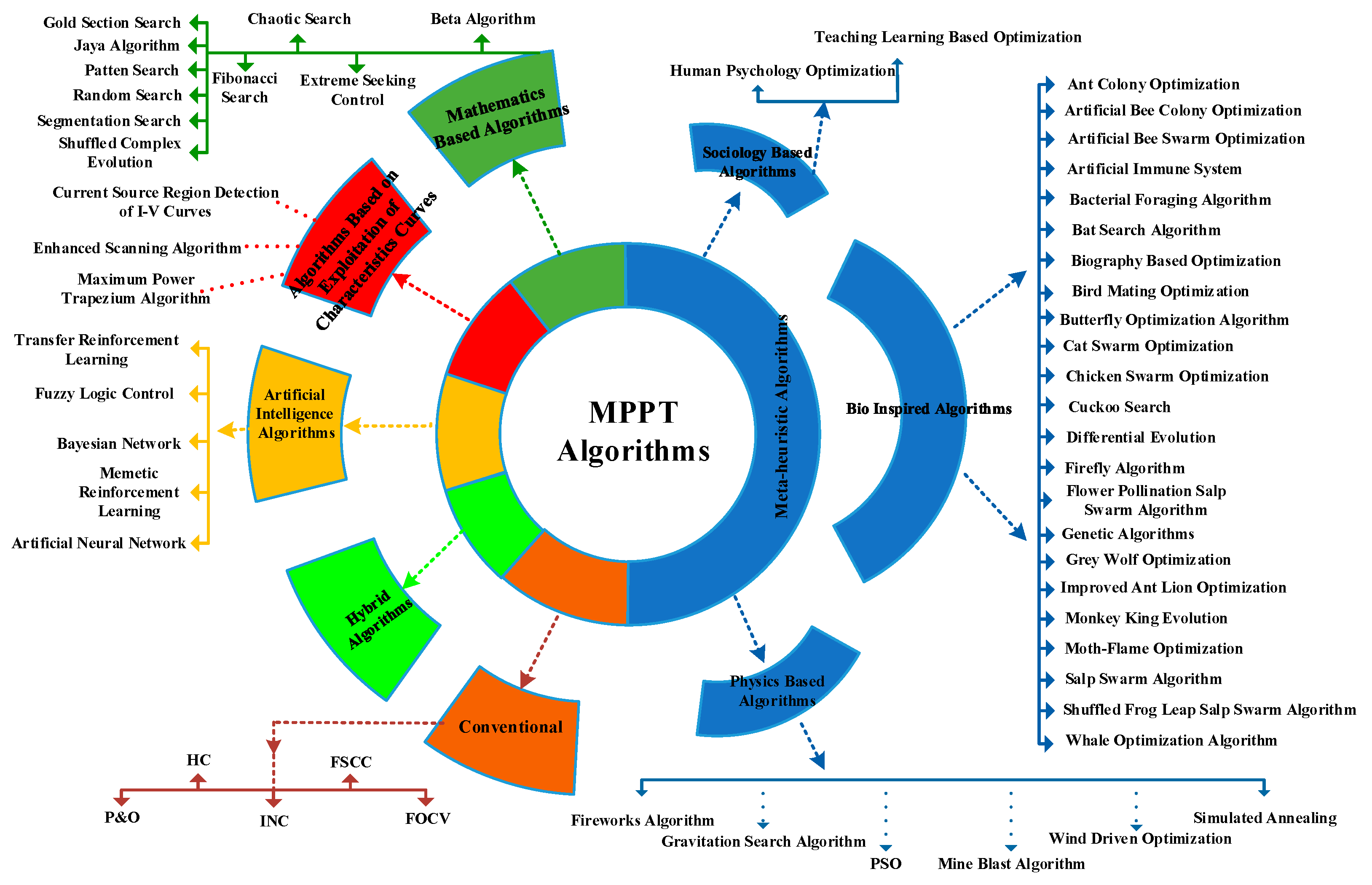
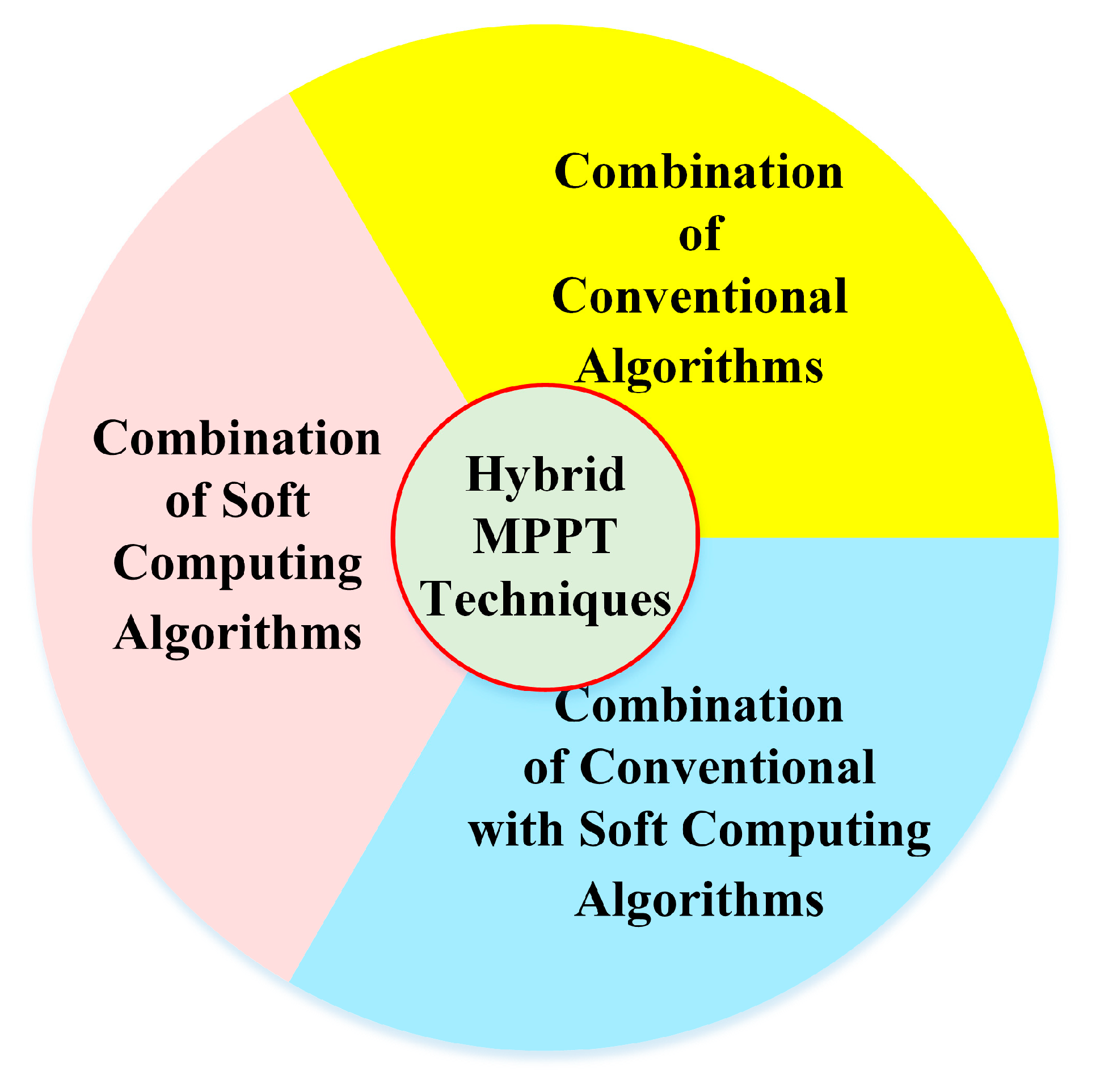
- This research work presents a review of more than 90 different MPPT techniques present in the literature and categorizes them into three types. The 1st type is the combination of two or more conventional MPPT techniques; the 2nd type is the combination of two or more soft computing techniques; and the 3rd type is the combination of conventional and soft computing methods;
- This manuscript summarizes numerous MPPT techniques and provides a comprehensive comparison considering different characteristics such as DC–DC converter topology, complexity level, tracking speed, steady-state oscillation, tracking accuracy, cost, etc.;
- Besides the MPPT technique, there are many other factors, e.g., the location and season of a PV system, PV panel tilts and orientations, conversion efficiency, the selection of a DC-DC converter, etc., that should be considered while installing a PV system. This work provides a comprehensive review of these factors;
- This manuscript provides a valuable path for future research in the field of hybrid MPPT techniques and will help the energy engineers to select an appropriate technique according to the project’s requirements.

| Ref. | PV Global Status | Primary Focus on Hybrid MPPT Methods | Secondary Focus on Hybrid MPPT Methods | Primary Focus on Non-Hybrid MPPT Methods | MPPT Selection Criteria | Comparative Analysis of MPPT Methods |
|---|---|---|---|---|---|---|
| [26] | x | ✓ | x | x | ✓ | ✓ |
| [27] | x | x | x | ✓ | x | ✓ |
| [28] | x | x | ✓ | ✓ | ✓ | ✓ |
| [29] | x | x | ✓ | ✓ | x | ✓ |
| [30] | x | x | x | ✓ | ✓ | ✓ |
| [31] | x | x | x | ✓ | x | x |
| [32] | x | x | ✓ | ✓ | x | ✓ |
| [33] | x | x | ✓ | ✓ | ✓ | ✓ |
| [34] | x | x | x | ✓ | x | x |
| [35] | ✓ | x | ✓ | ✓ | ✓ | ✓ |
| [36] | ✓ | x | x | ✓ | x | ✓ |
| [37] | ✓ | x | ✓ | ✓ | x | ✓ |
| [38] | x | x | ✓ | ✓ | x | ✓ |
| [39] | x | x | x | ✓ | x | ✓ |
| [40] | ✓ | x | x | ✓ | x | ✓ |
| Proposed | ✓ | ✓ | x | x | ✓ | ✓ |
2. Hybrid MPPT Algorithms
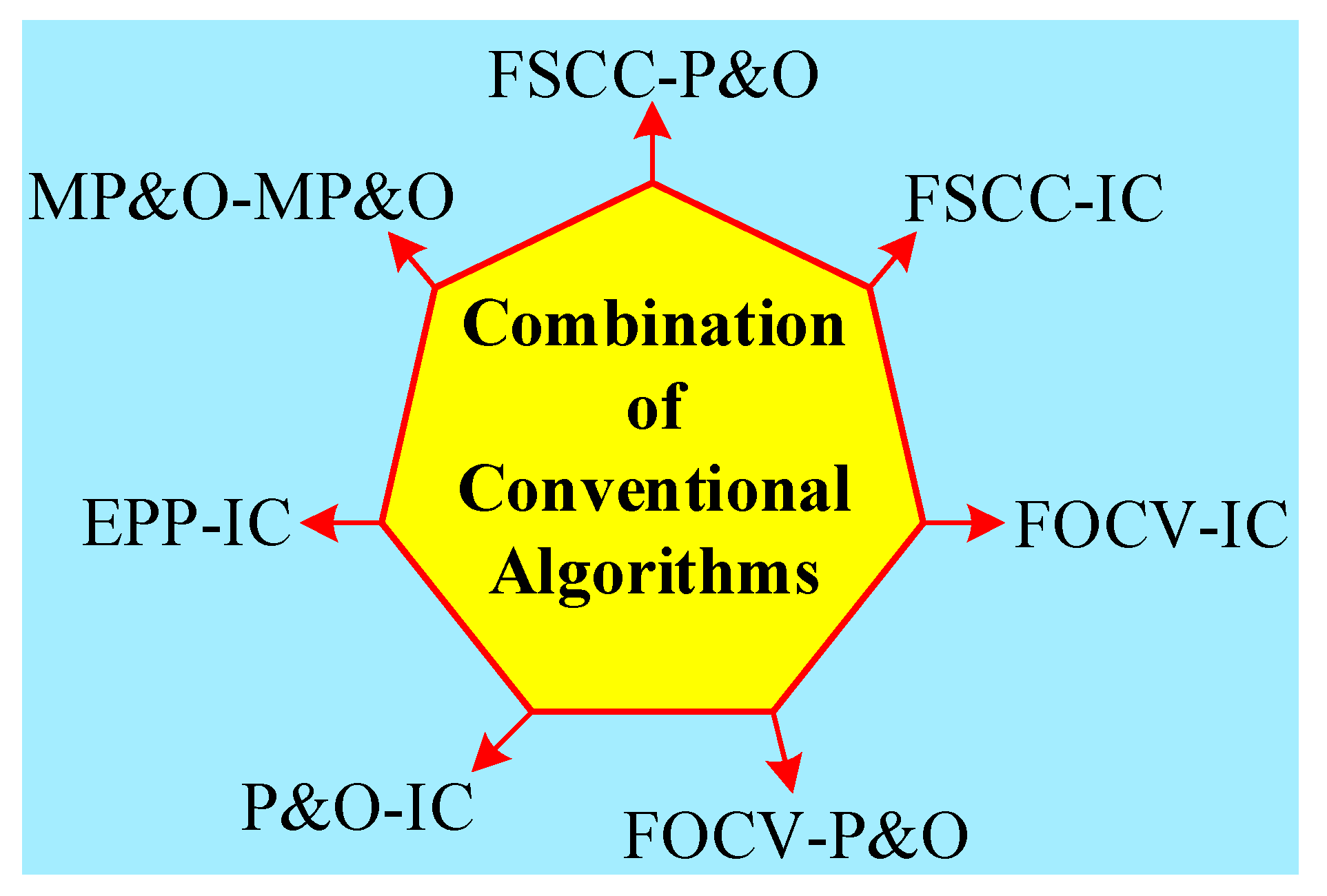
2.1. Combination of Conventional Algorithms
2.1.1. P and O with Fractional Short Circuit Current (FSCC)
2.1.2. FSCC with IC

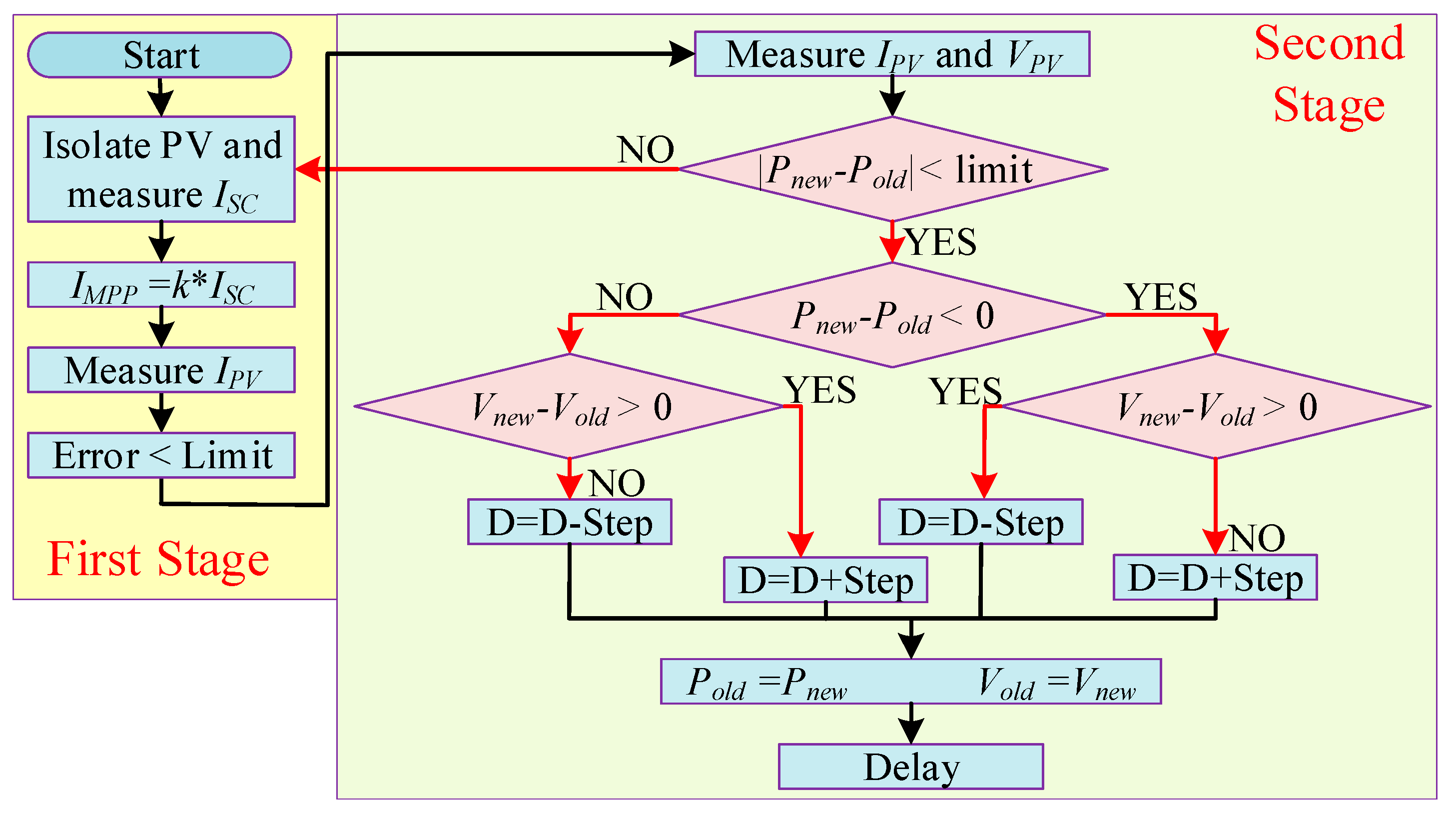
2.1.3. FOCV with P and O
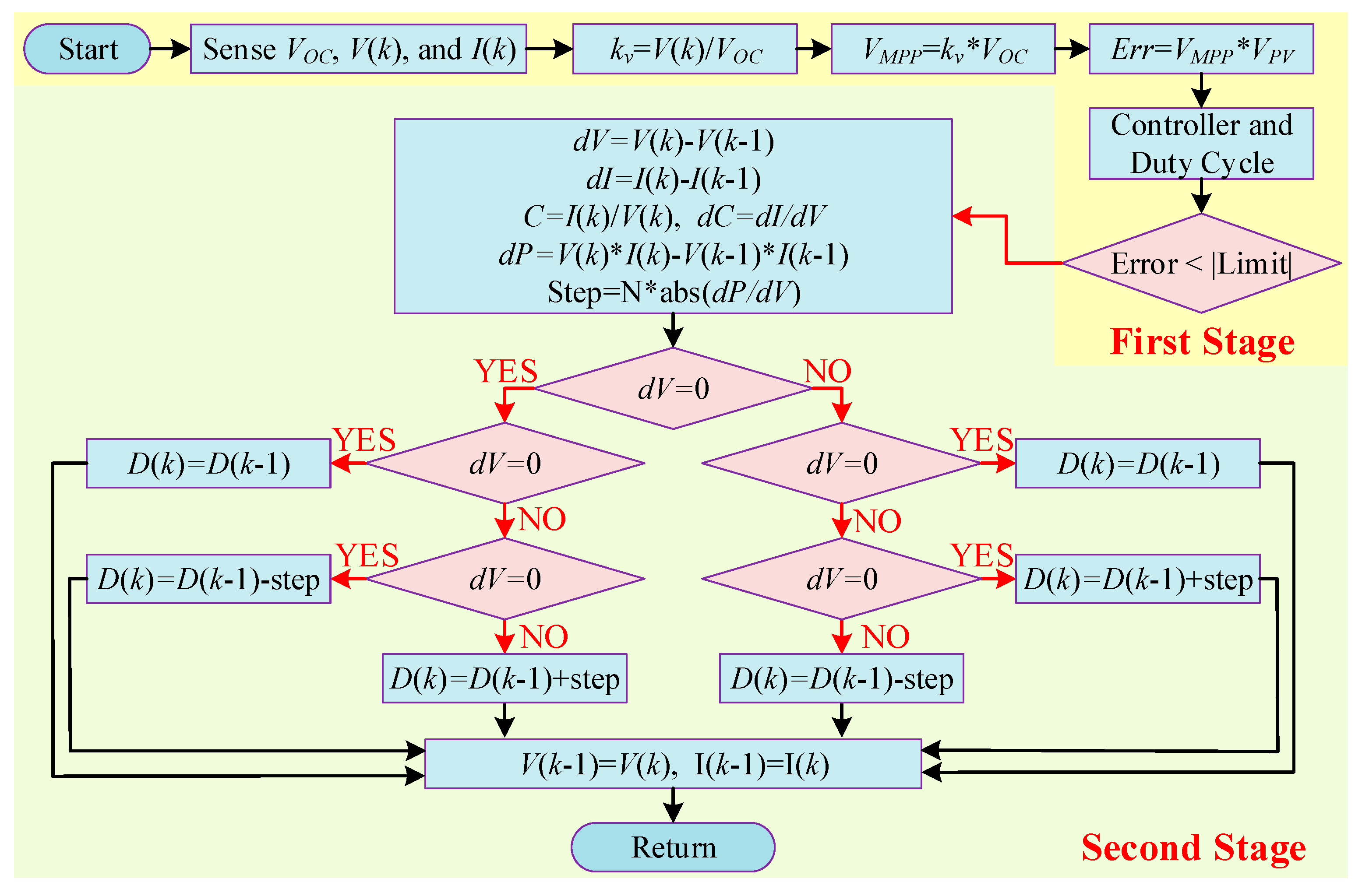
2.1.4. FOCV with IC
2.1.5. P and O with IC
2.1.6. Modified Perturb and Observe (MP and O)
2.1.7. Estimation-Perturb-Perturb (EPP) with IC
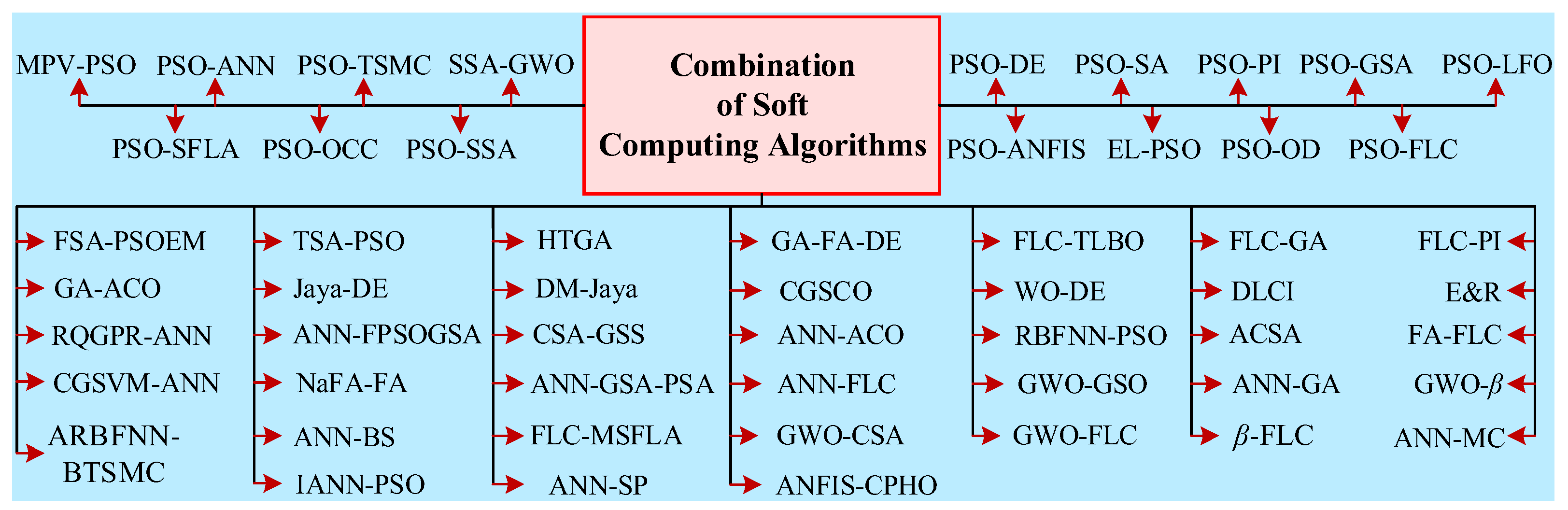
2.2. Combination of Soft Computing Algorithms
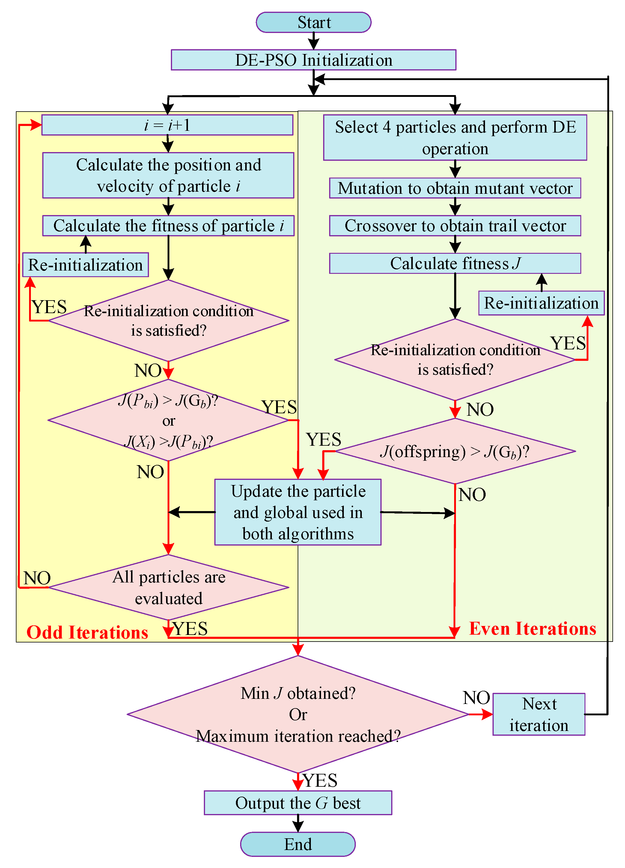
2.2.1. PSO with DE
2.2.2. PSO with Proportional Integral (PI) Controller
2.2.3. PSO with Overall Distribution (OD)
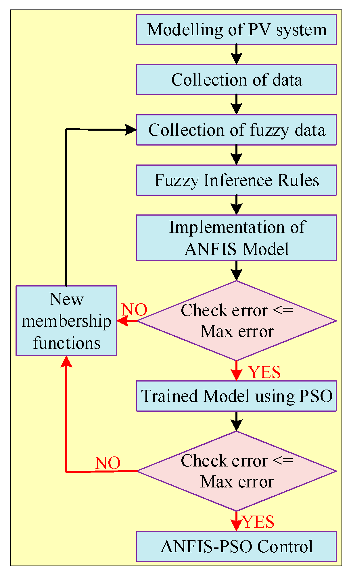
2.2.4. PSO with Adaptive Neuro Fuzzy Inference System (ANFIS)
2.2.5. PSO with One Cycle Control (OCC)
2.2.6. Enhanced Leader PSO (EL-PSO)
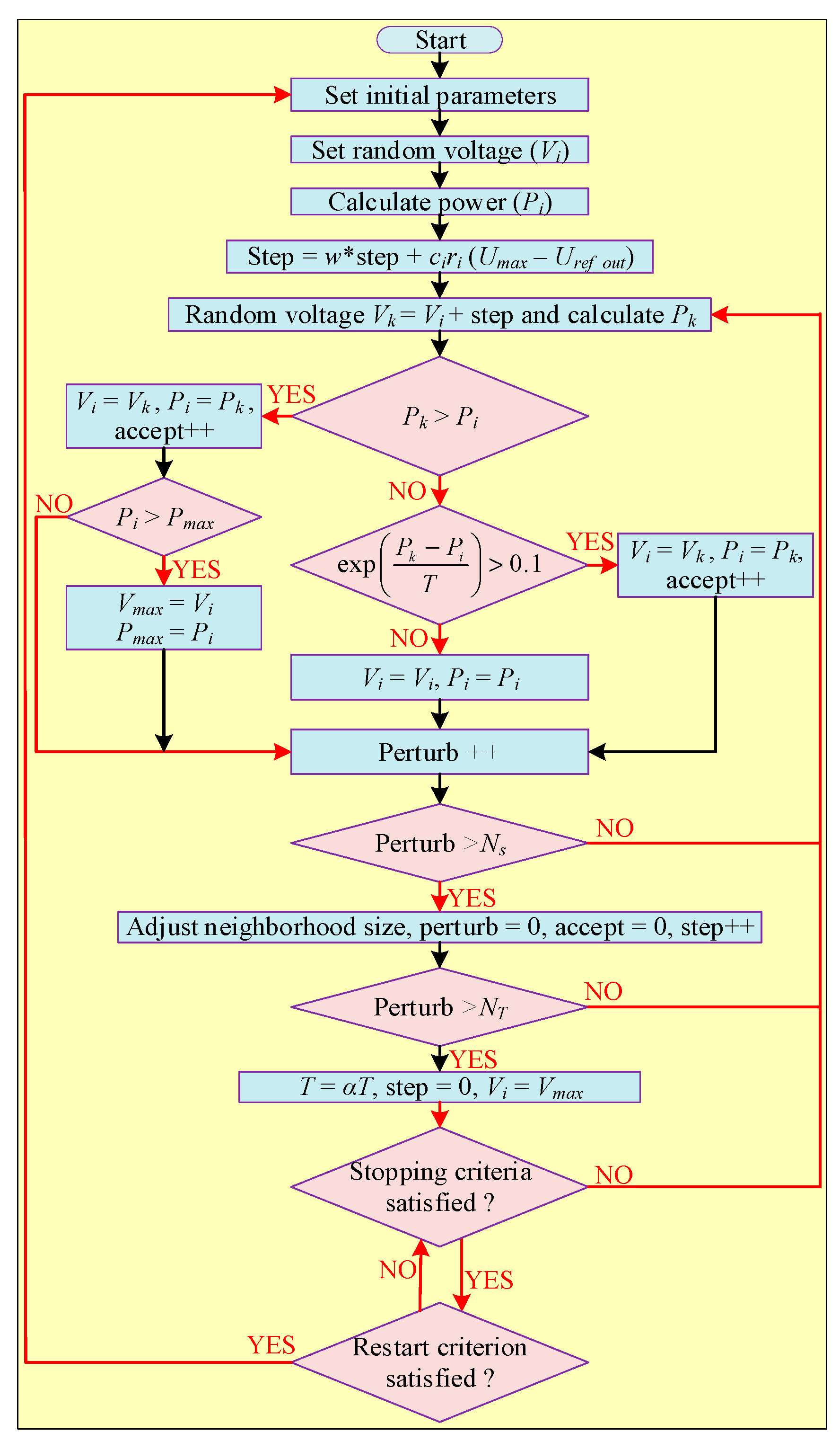
2.2.7. PSO with Simulated Annealing (SA)
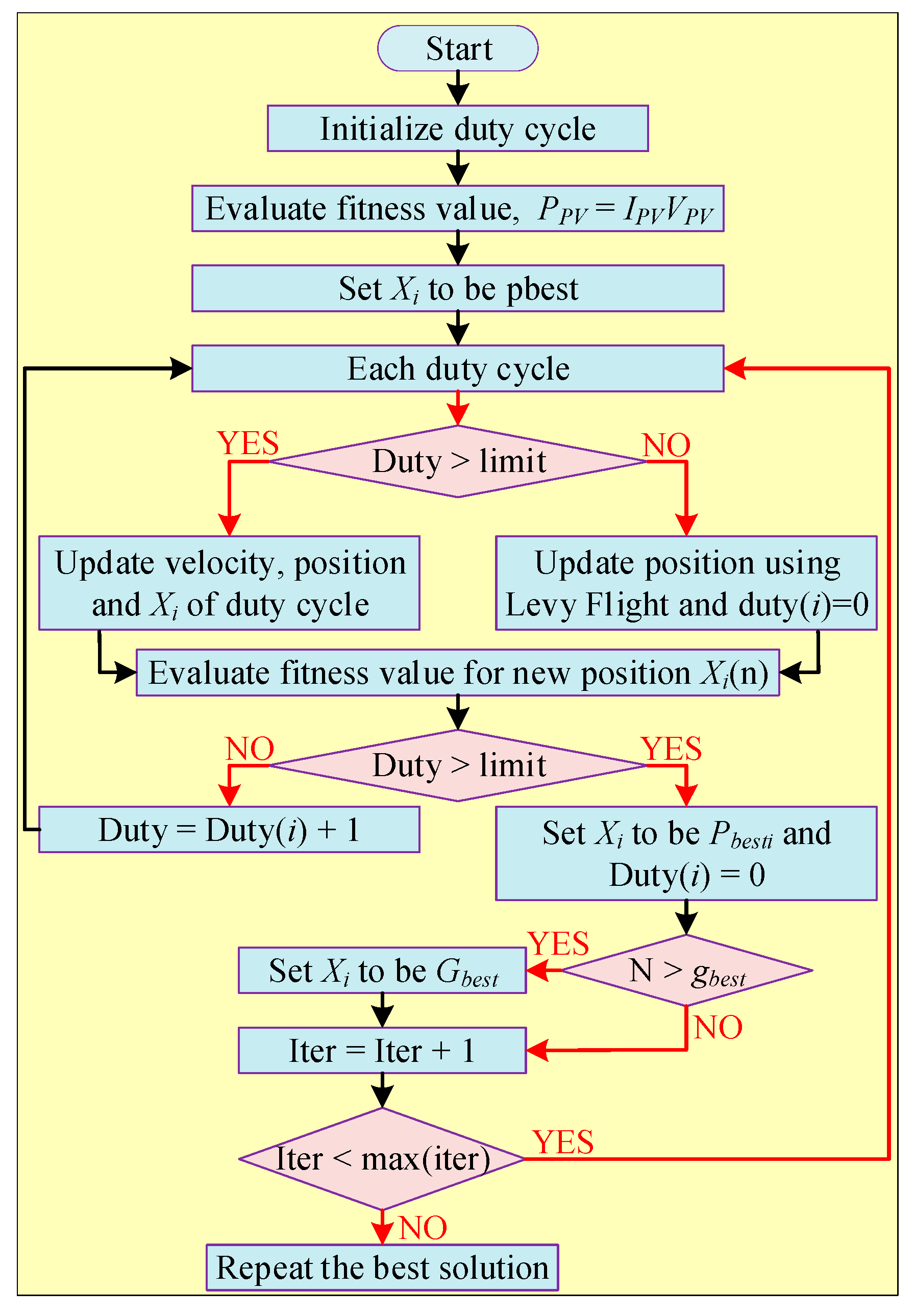
2.2.8. PSO with Levy Flight Optimization (LFO)


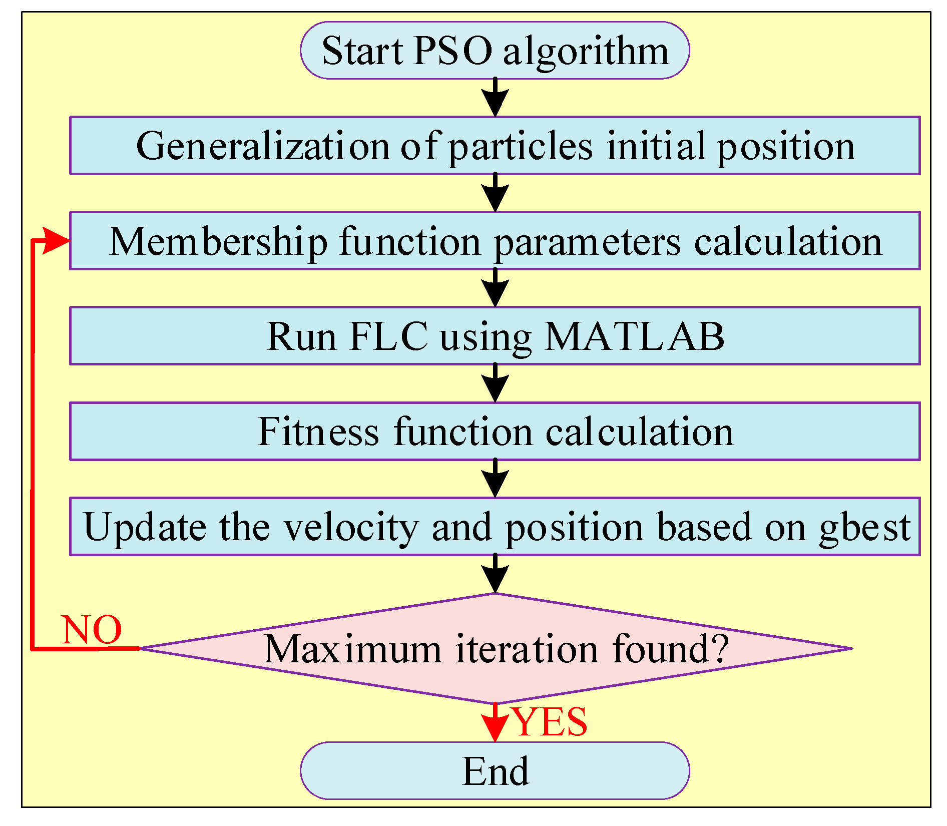
2.2.9. PSO with FLC
2.2.10. PSO with Terminal Sliding Mode Controller (TSMC)
2.2.11. PSO with GSA
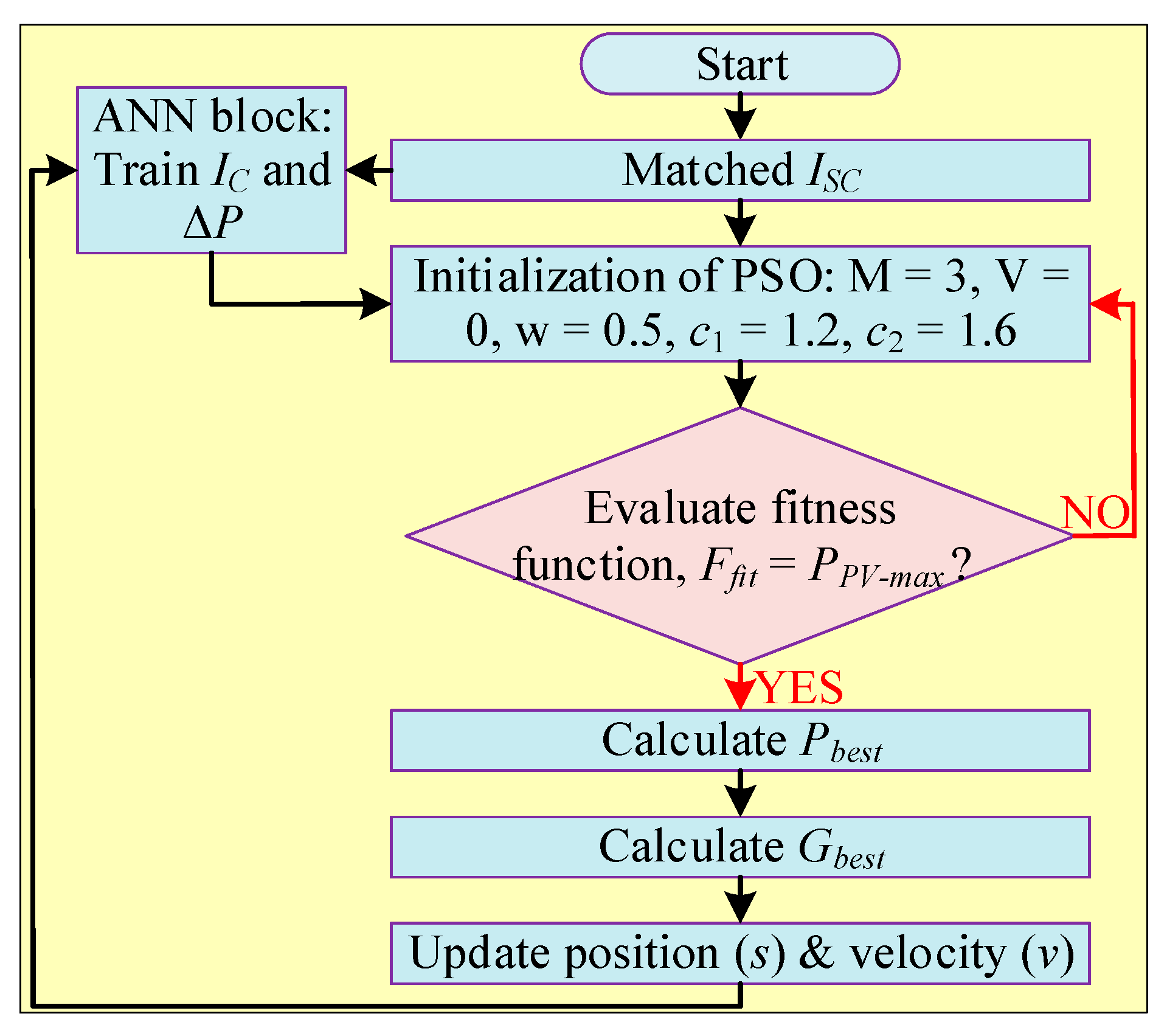
2.2.12. PSO with ANN
2.2.13. PSO with Shuffled Frog Leaping Algorithm
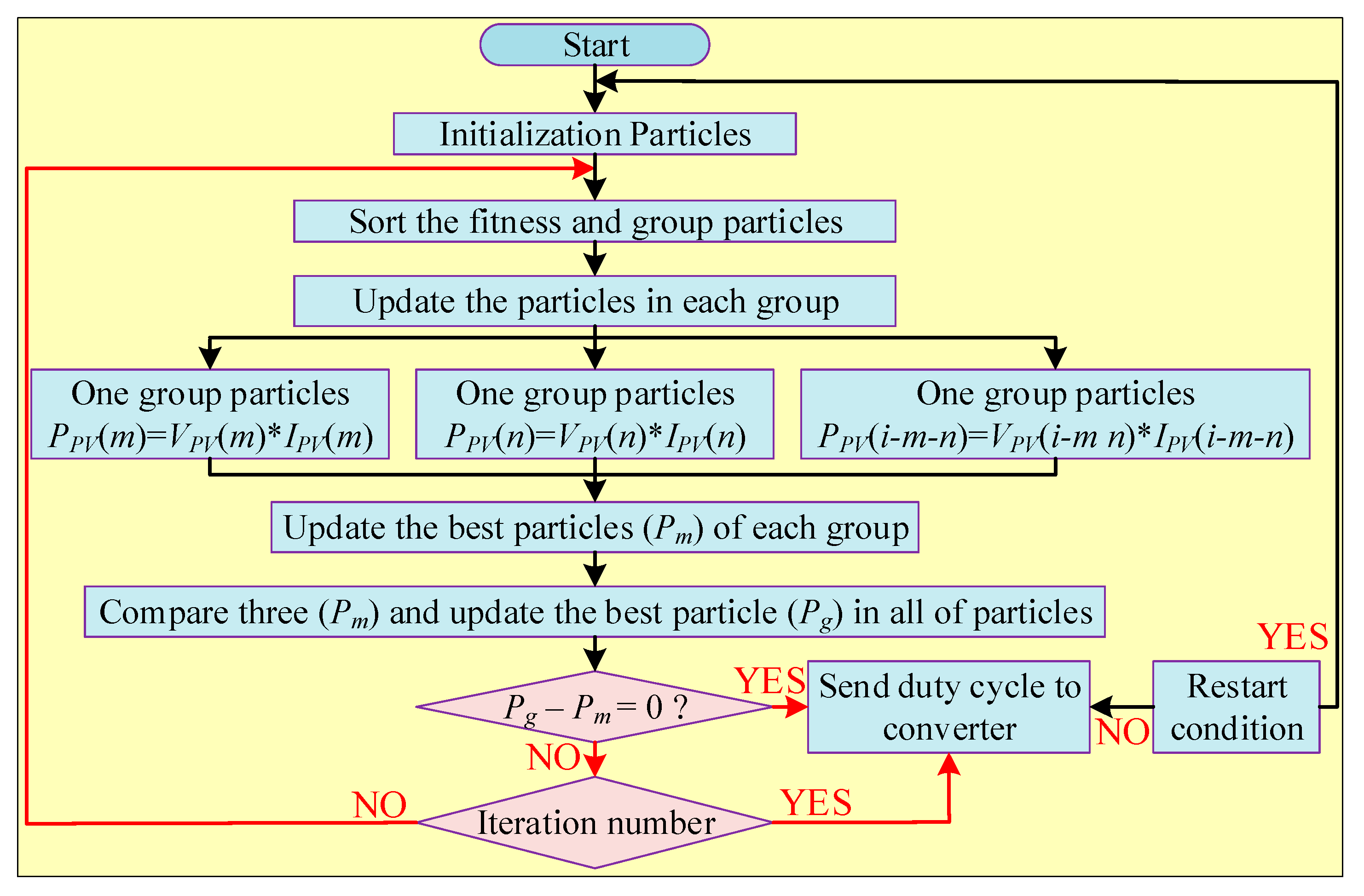
2.2.14. Modified Particle Velocity (MPV)-Based PSO
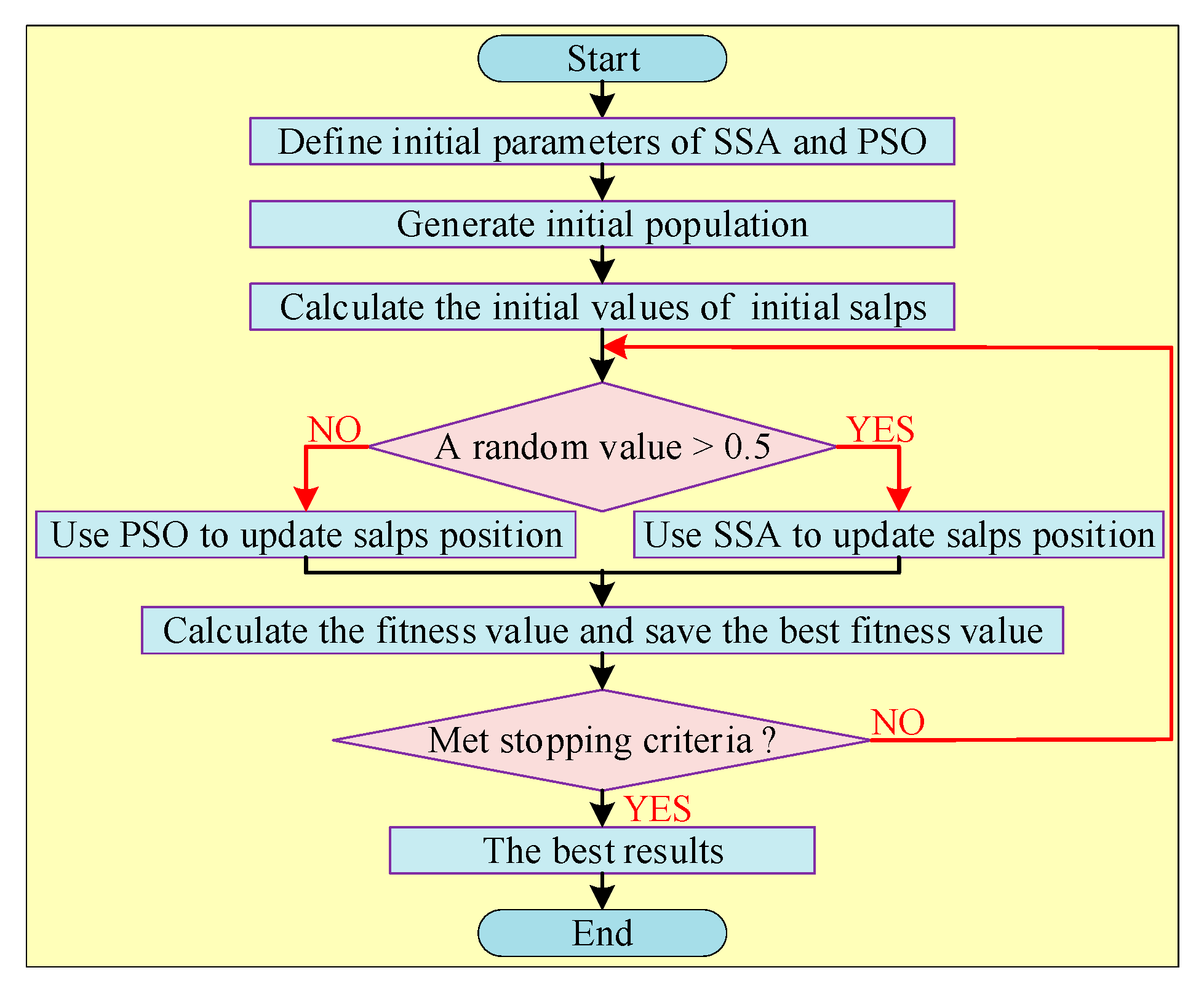
2.2.15. PSO with SSA
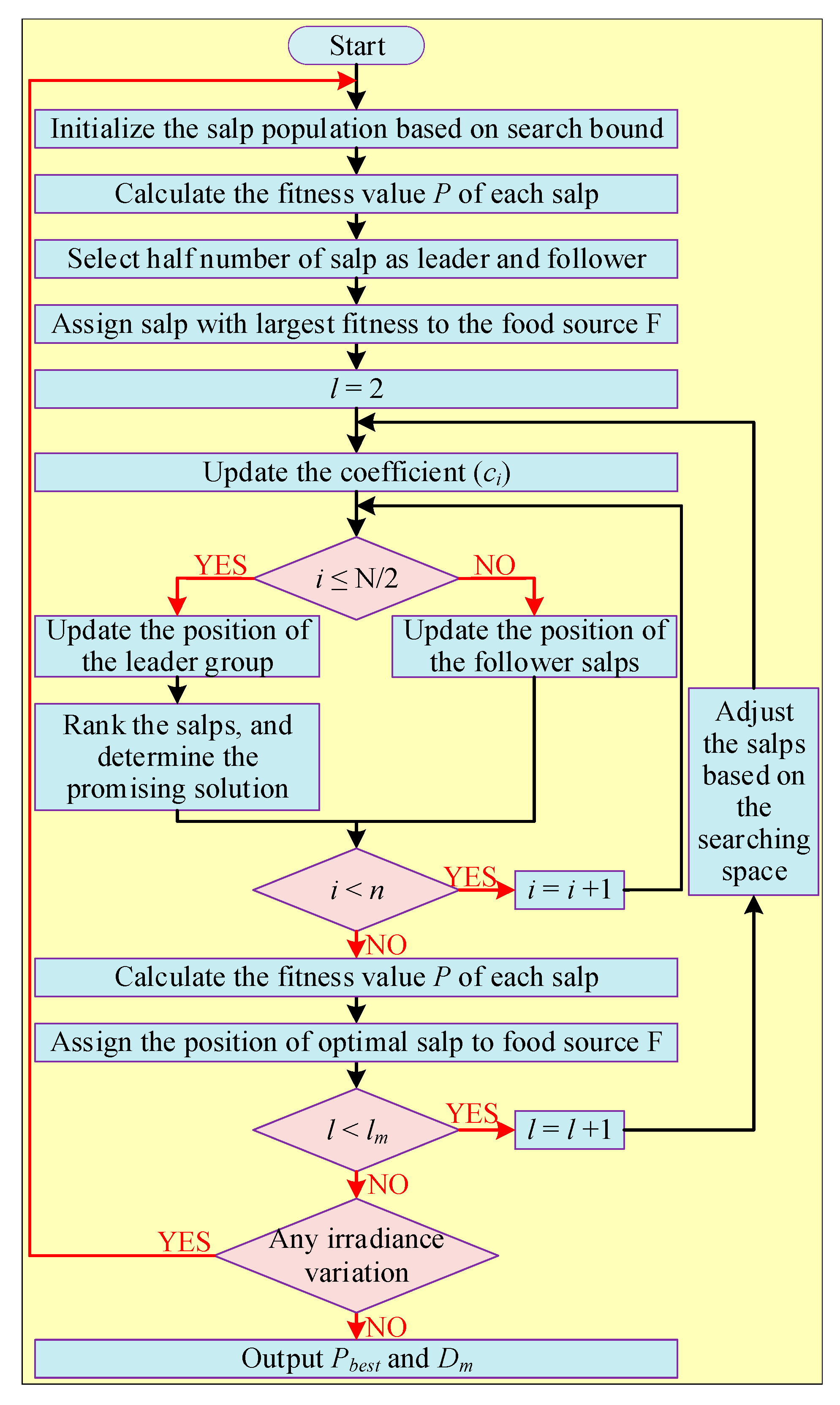
2.2.16. SSA with GWO
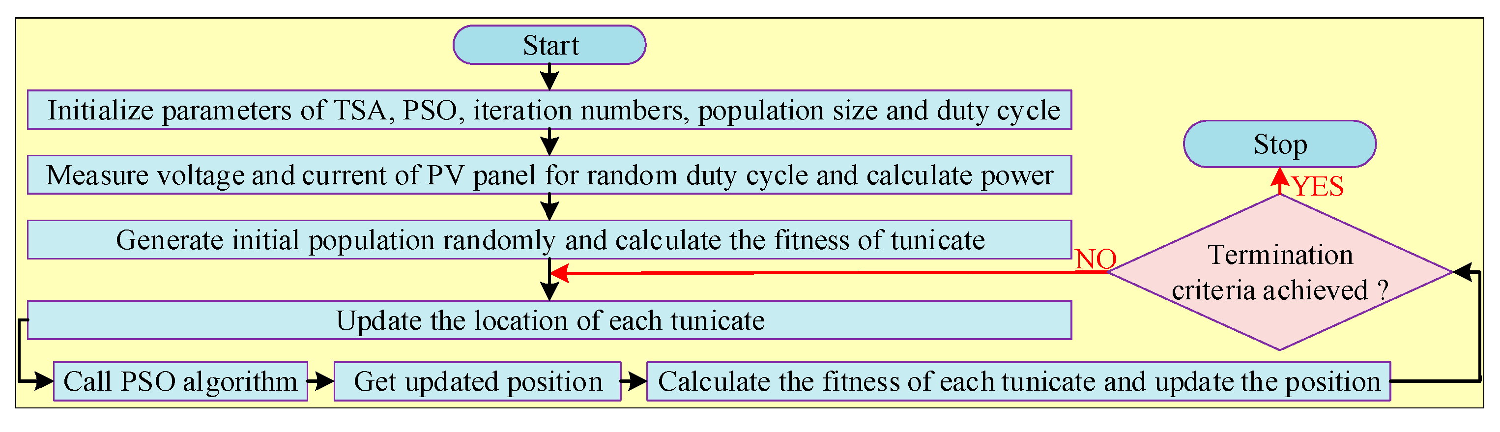
2.2.17. Tunicate Swarm Algorithm (TSA) with PSO
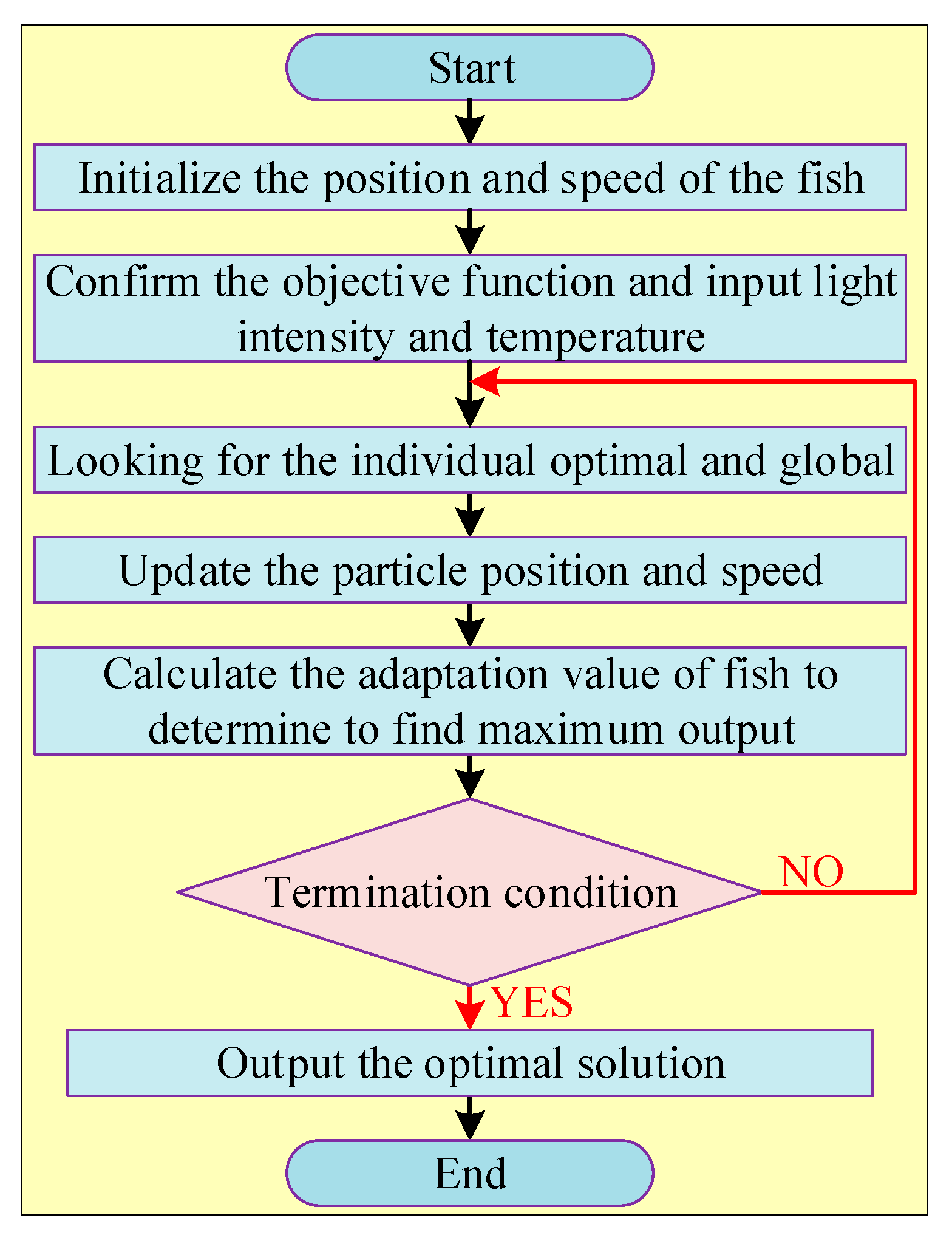
2.2.18. Artificial Fish Swarm Algorithm (FSA) with PSO
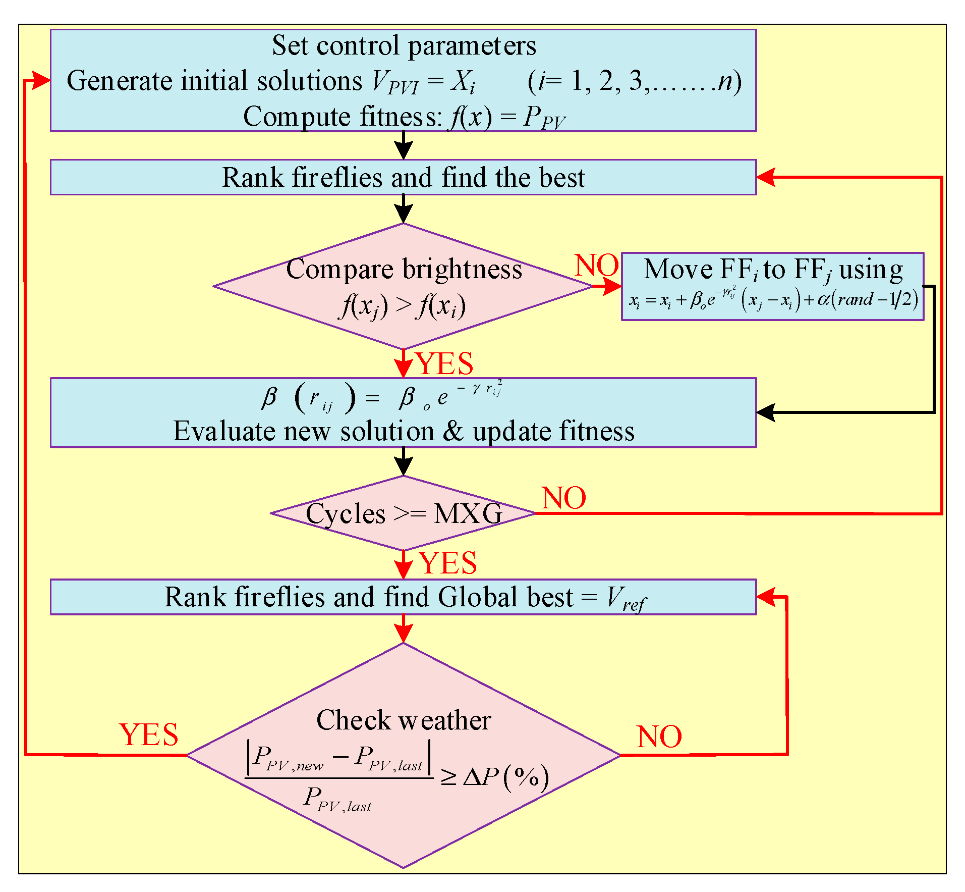
2.2.19. Fusion Firefly Algorithms
2.2.20. FA with FLC
2.2.21. Adaptive Cuckoo Search Algorithm (ACSA)
2.2.22. CSA with Golden Section Search (GSS)
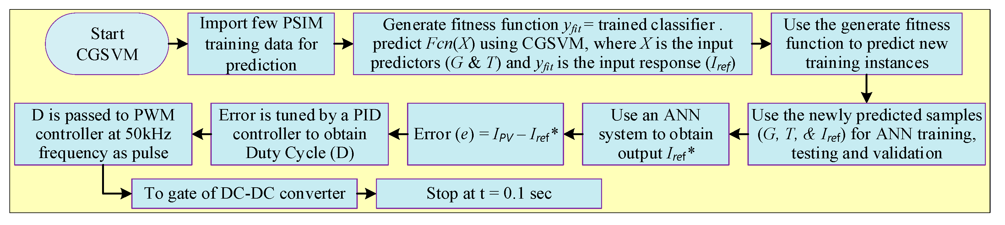
2.2.23. ANN with Rational Quadratic Gaussian Process Regression (RQGPR) and Coarse Gaussian Support Vector Machine (CGSVM)
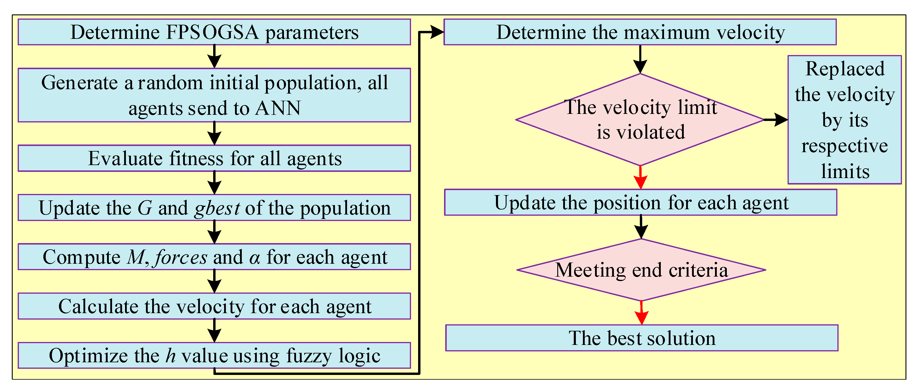
2.2.24. ANN with Fuzzy Particle Swarm Optimization Gravitational Search Algorithm (FPSOGSA)
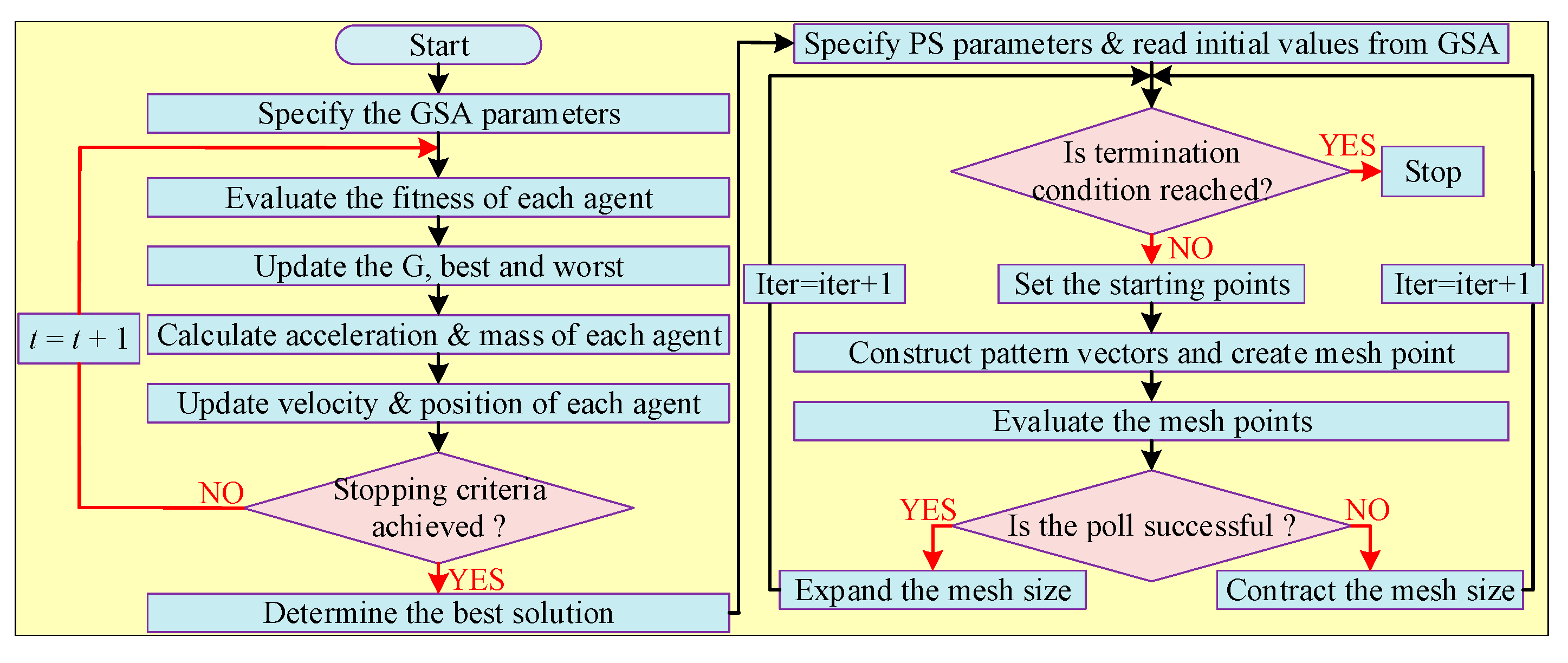
2.2.25. ANN with GSA and Pattern Search Algorithm (PSA)
2.2.26. ANN with GA
2.2.27. ANN with FLC
2.2.28. ANN with Scanning Procedure (SP) Technique
2.2.29. ANN with Ant Colony Optimization (ACO)
2.2.30. ANN with Monte Carlo (MC) Filtering
2.2.31. ANN with Back Stepping (BS) Controller
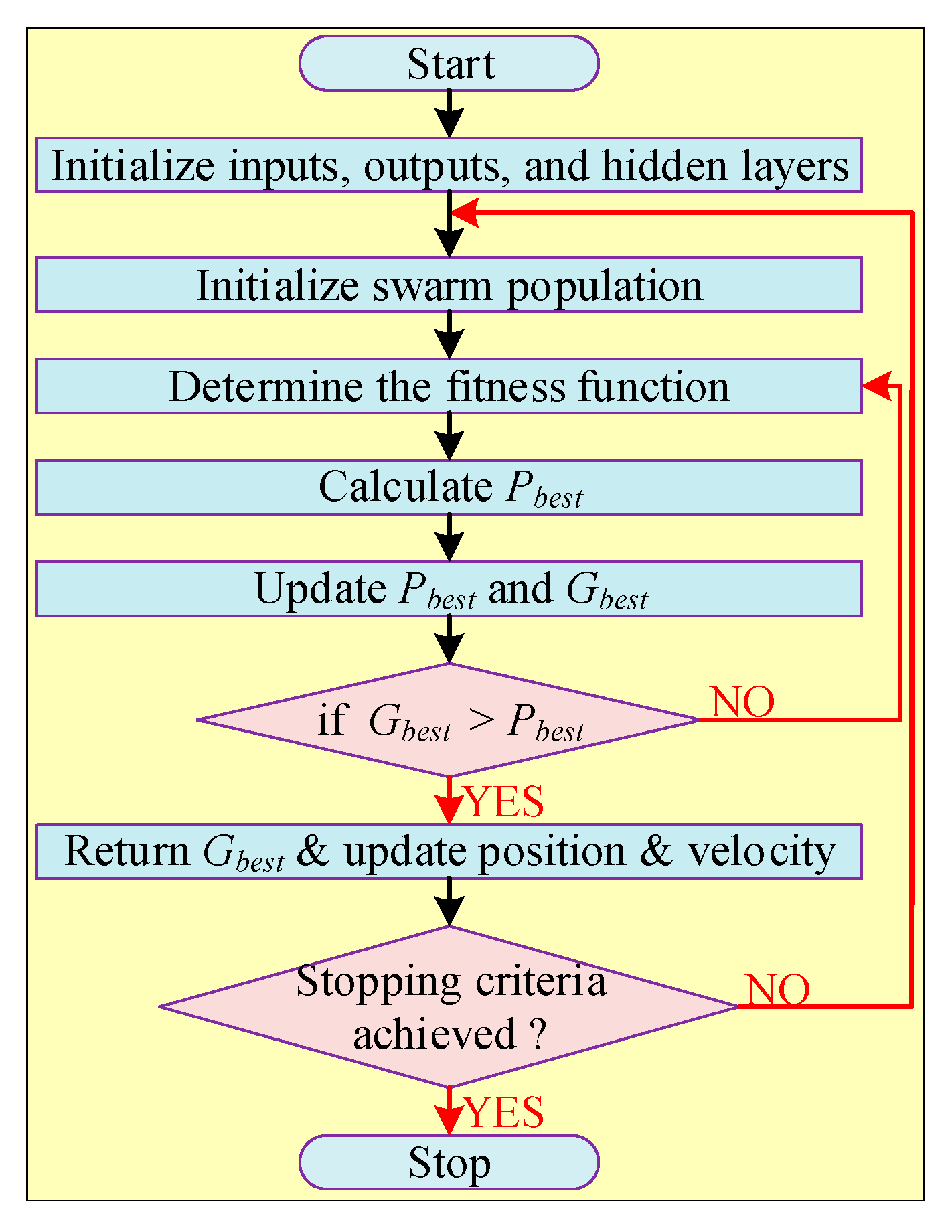
2.2.32. Improved ANN with PSO
2.2.33. Radial Basis Function Neural Network (RBFNN) with PSO
2.2.34. RBFNN with Back-Stepping Terminal Sliding Mode Controller (BTSMC)
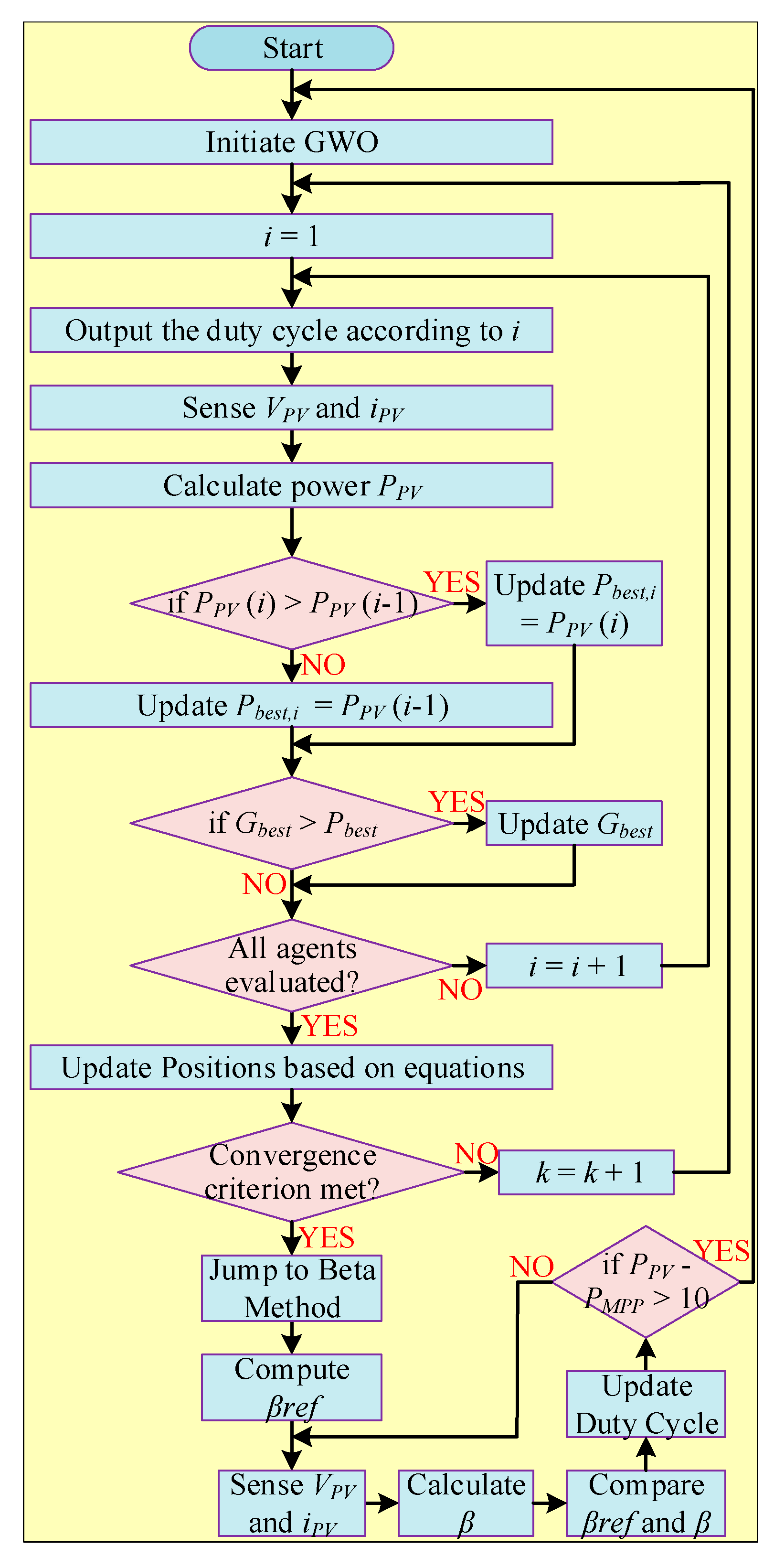
2.2.35. GWO with β-Algorithm
2.2.36. GWO with FLC
2.2.37. GWO with Crow Search Algorithm (CSA)
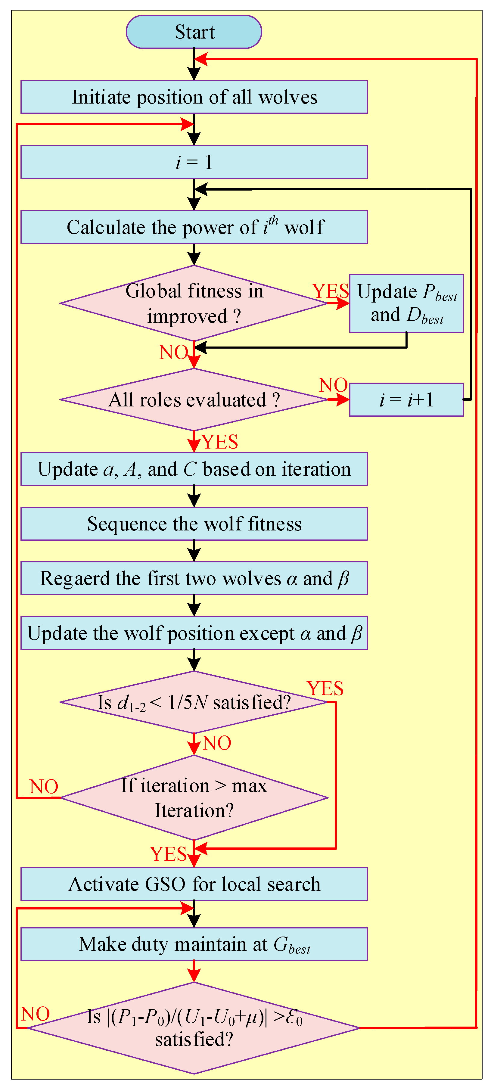
2.2.38. GWO with Golden Section Optimization (GSO)
2.2.39. ANFIS with Crowded Plant Height Optimization (CPHO)
2.2.40. FLC with MSFLA
2.2.41. Beta Fuzzy Logic Controller
2.2.42. FLC with GA
2.2.43. FLC with PI
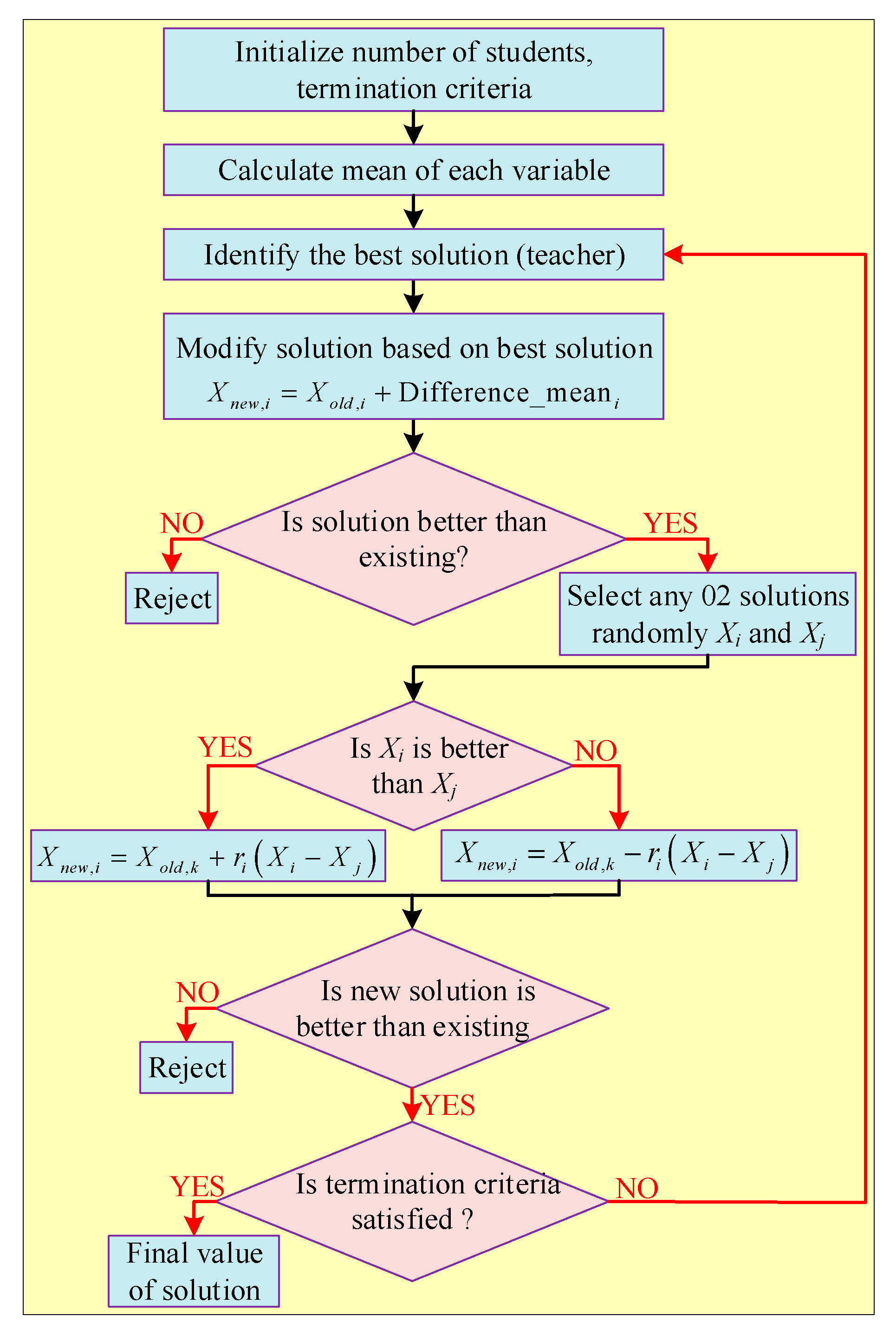
2.2.44. FLC with Teaching Learning-Based Optimization (TLBO)
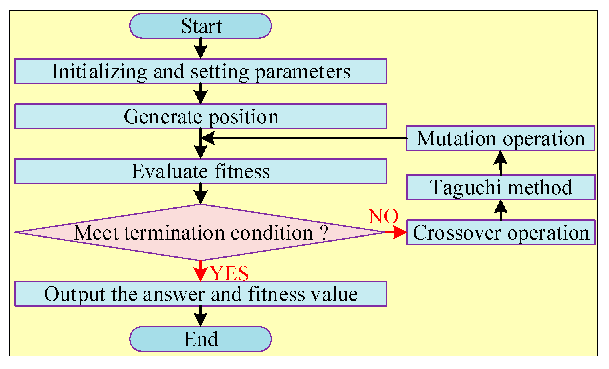
2.2.45. Hybrid Taguchi Genetic Algorithm (HTGA)
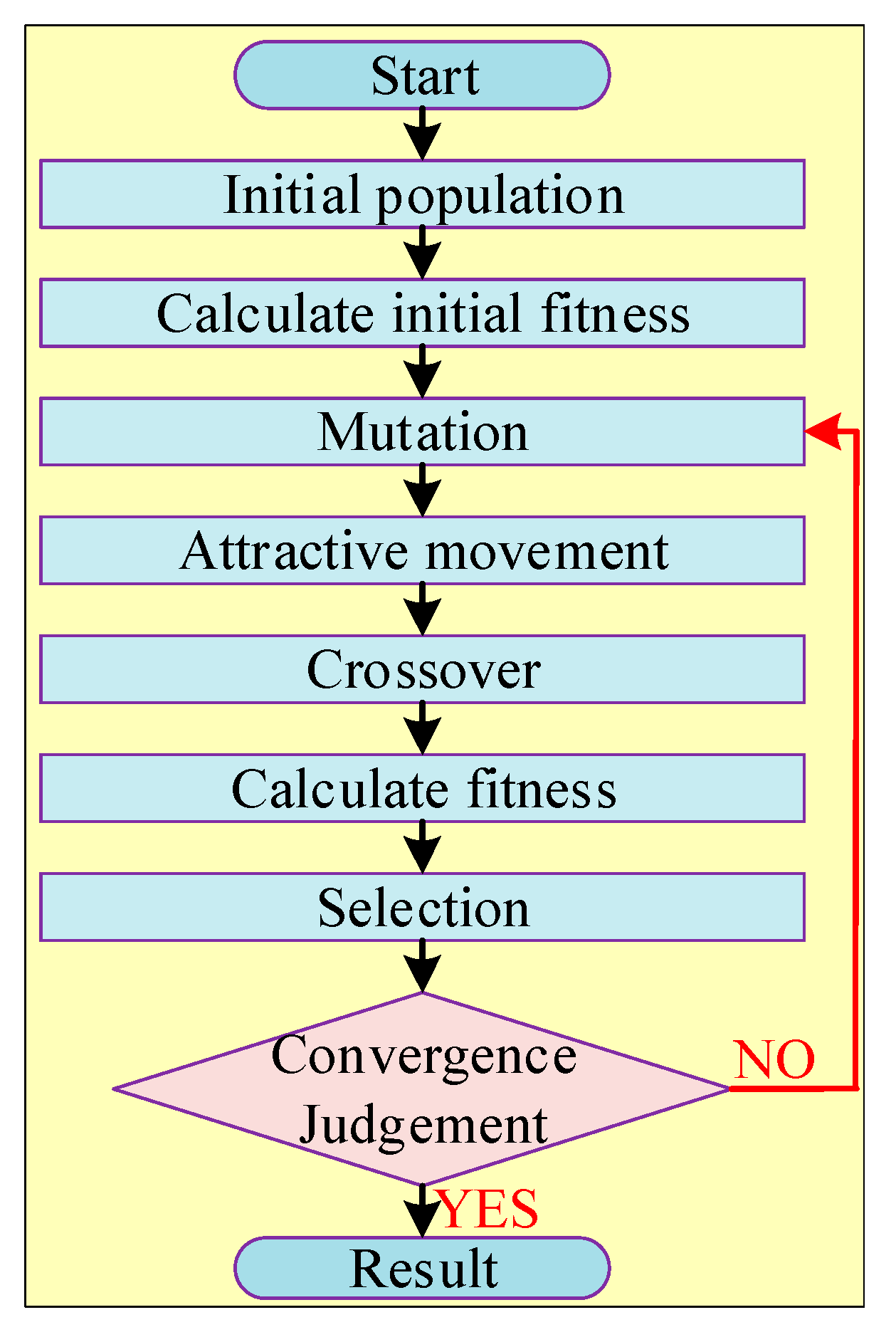
2.2.46. GA with FA and DE
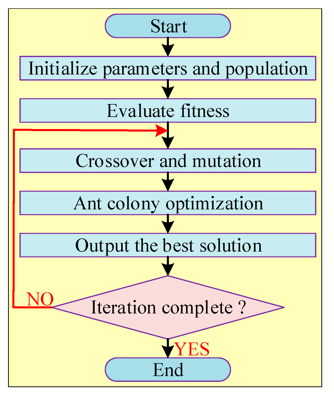
2.2.47. GA with ACO
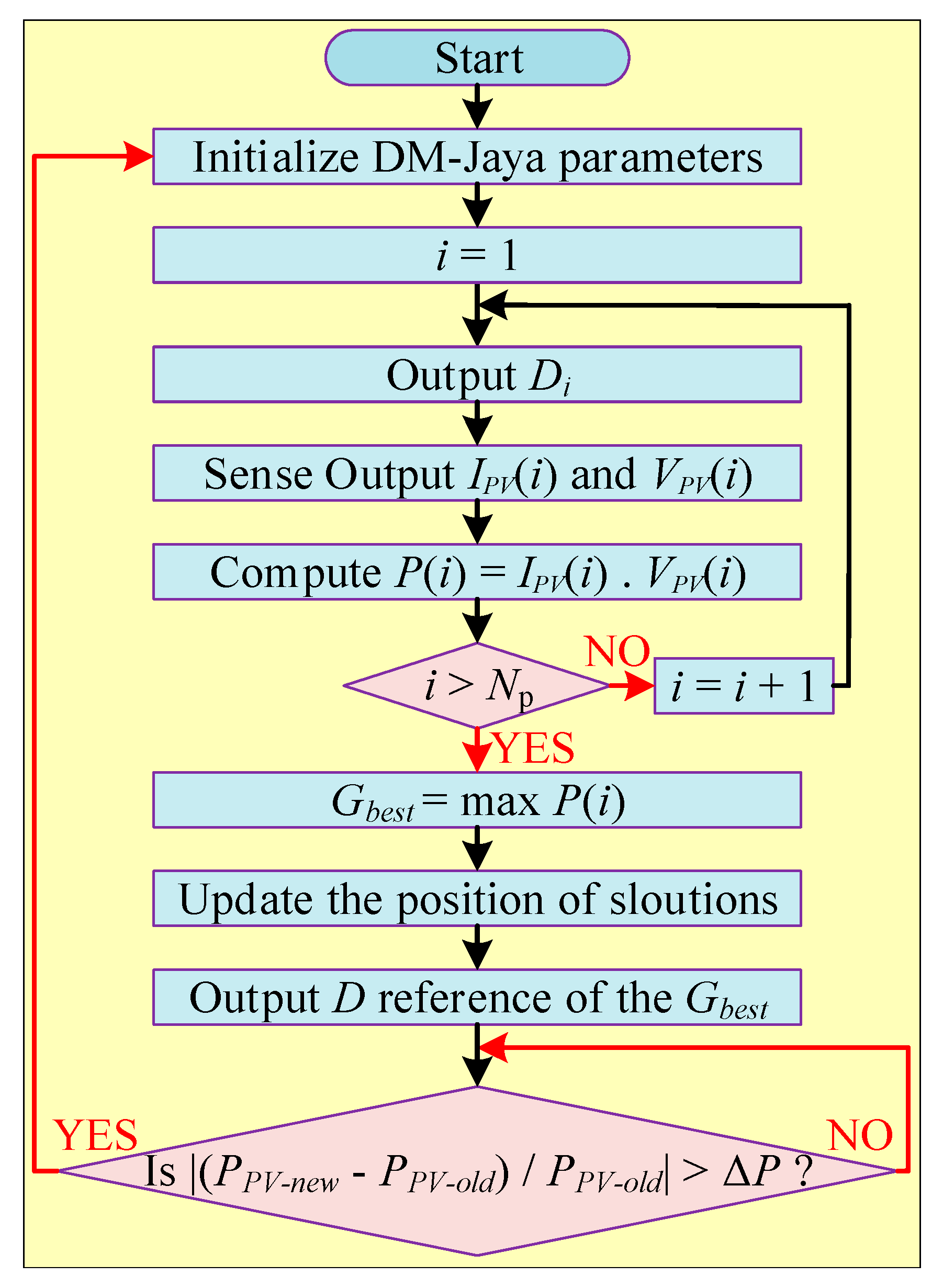
2.2.48. Deterministic Modified Jaya (DM-Jaya) Method
2.2.49. Jaya Method with DE
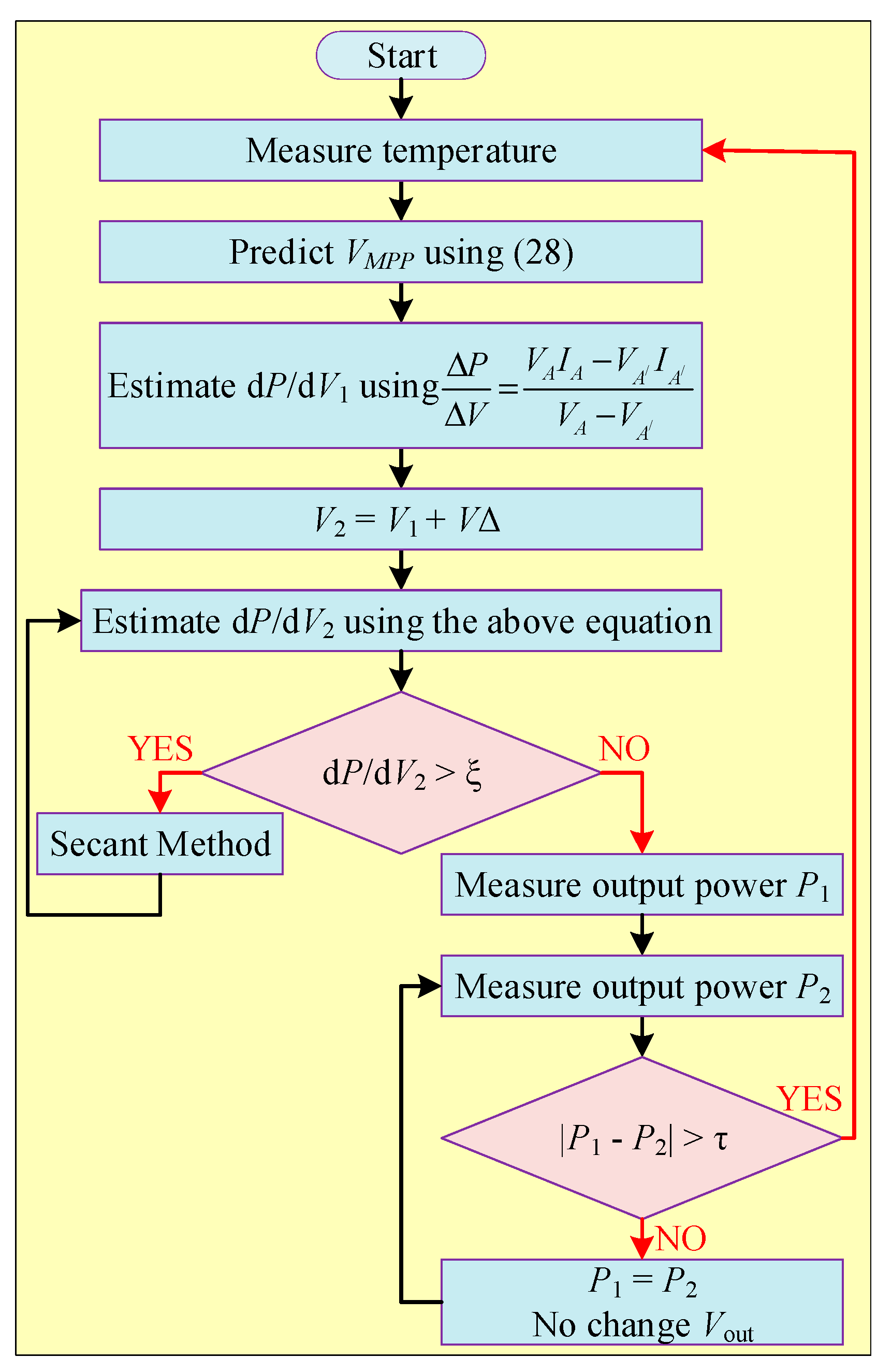
2.2.50. Estimation and Revision (E and R) Method
2.2.51. Whale Optimization (WO) with DE
2.2.52. Dynamic Leader-Based Collective Intelligence (DLCI) Algorithm
2.2.53. Cauchy and Gaussian Sine Cosine Optimization (CGSCO)
2.3. Combination of Conventional with Soft Computing Algorithms
2.3.1. P and O with Power Increment (PInc)
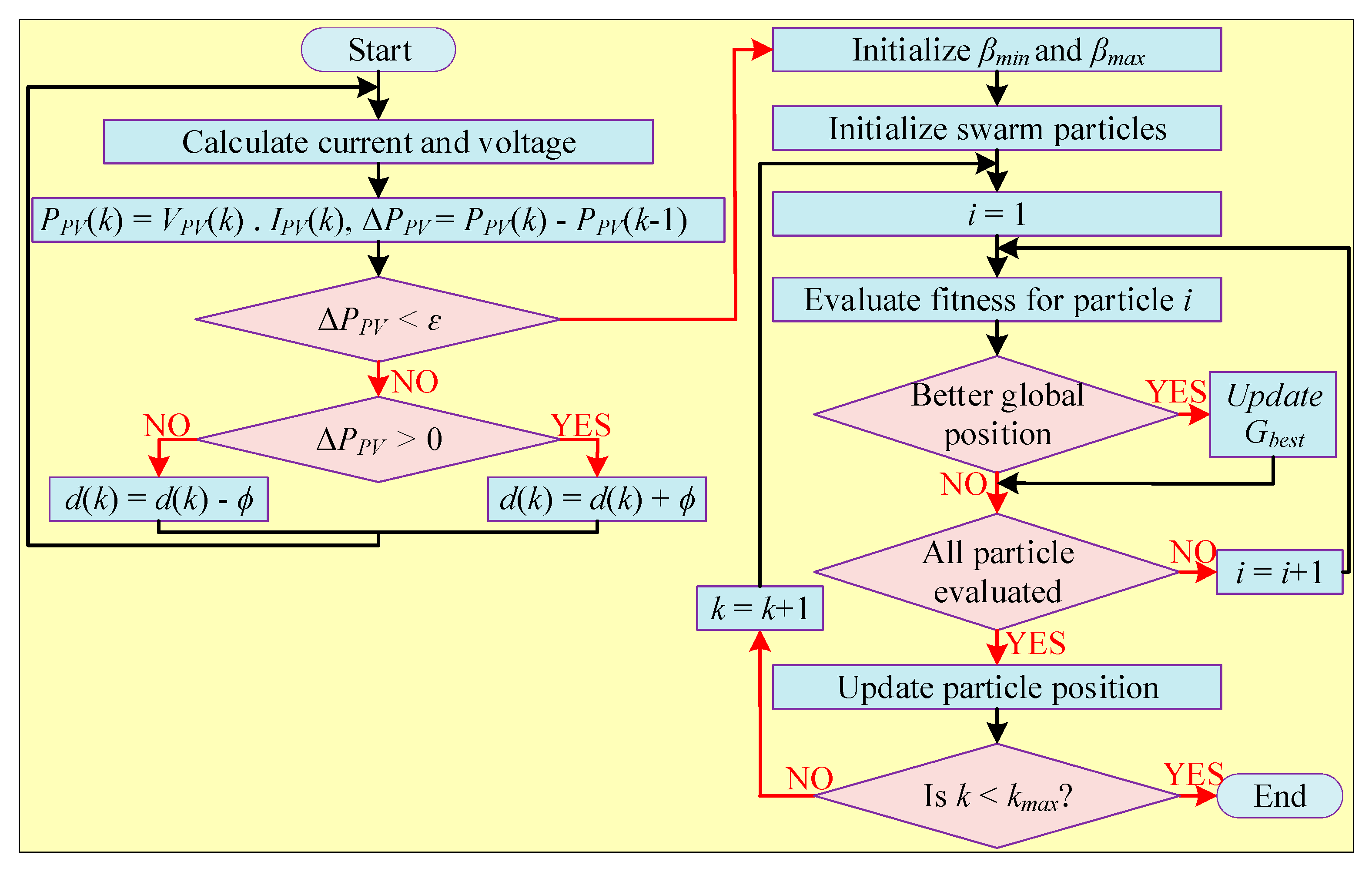
2.3.2. P and O with PSO
2.3.3. P and O with Improved PSO
2.3.4. P and O with FLC
2.3.5. SSA with P and O
2.3.6. GWO with P and O
2.3.7. P and O with Artificial Bee Colony (ABC)
2.3.8. P and O with Adaptive Integral Derivative Sliding Mode (AIDSM) Controller
2.3.9. P and O with Fireworks Algorithm (FWA)
2.3.10. P and O with ACO
2.3.11. FLC with Adaptive P and O
2.3.12. MP and O with FLC
2.3.13. P and O with GSA
2.3.14. P and O with Surface-Based Polynomial Fitting (SPF)
2.3.15. P and O with SA
2.3.16. Simplified Accelerated Particle Swarm Optimization with Hill Climbing
2.3.17. Incremental Conductance with FLC
2.3.18. IC with GOA
2.3.19. IC with Moth Flame Optimizer
2.3.20. IC with Parallel and Compact Pigeon-Inspired Optimization
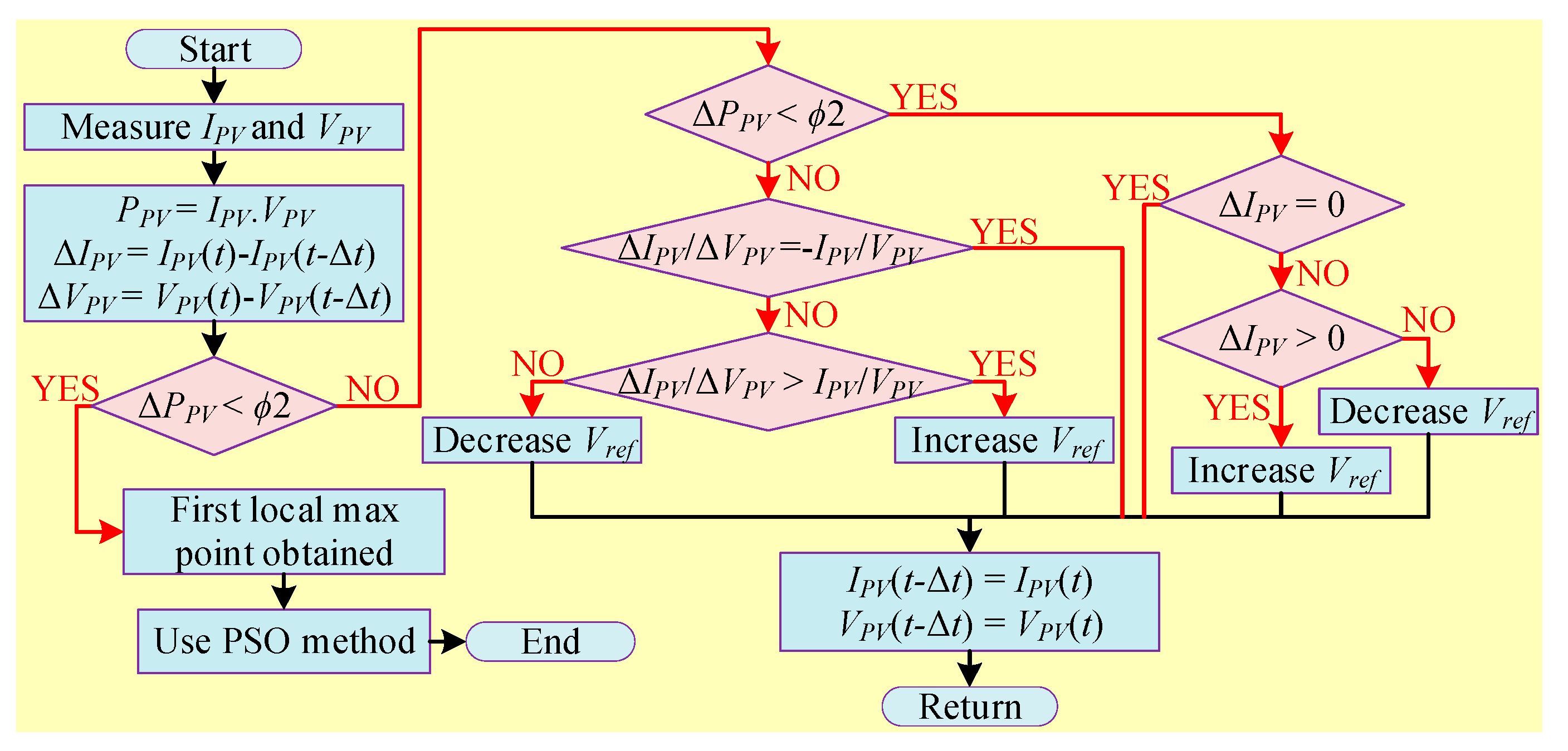
2.3.21. IC with PSO
2.3.22. IC with Dragonfly Optimization
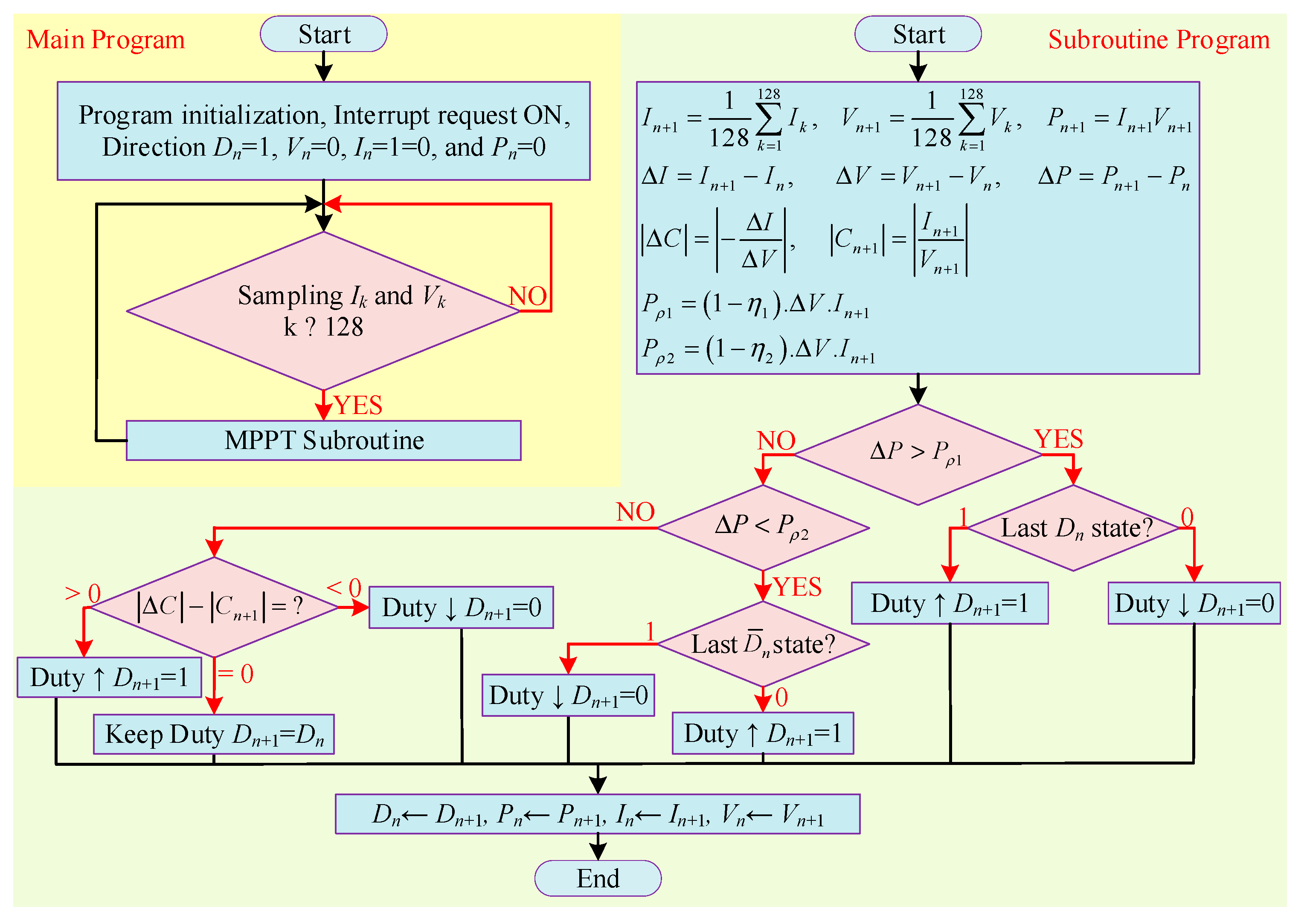
2.3.23. PInc with IC
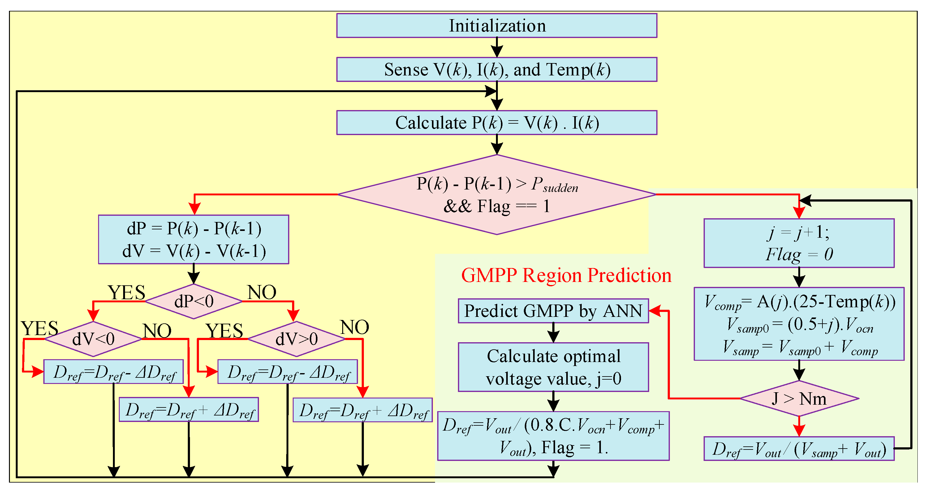
2.3.24. ANN with P and O
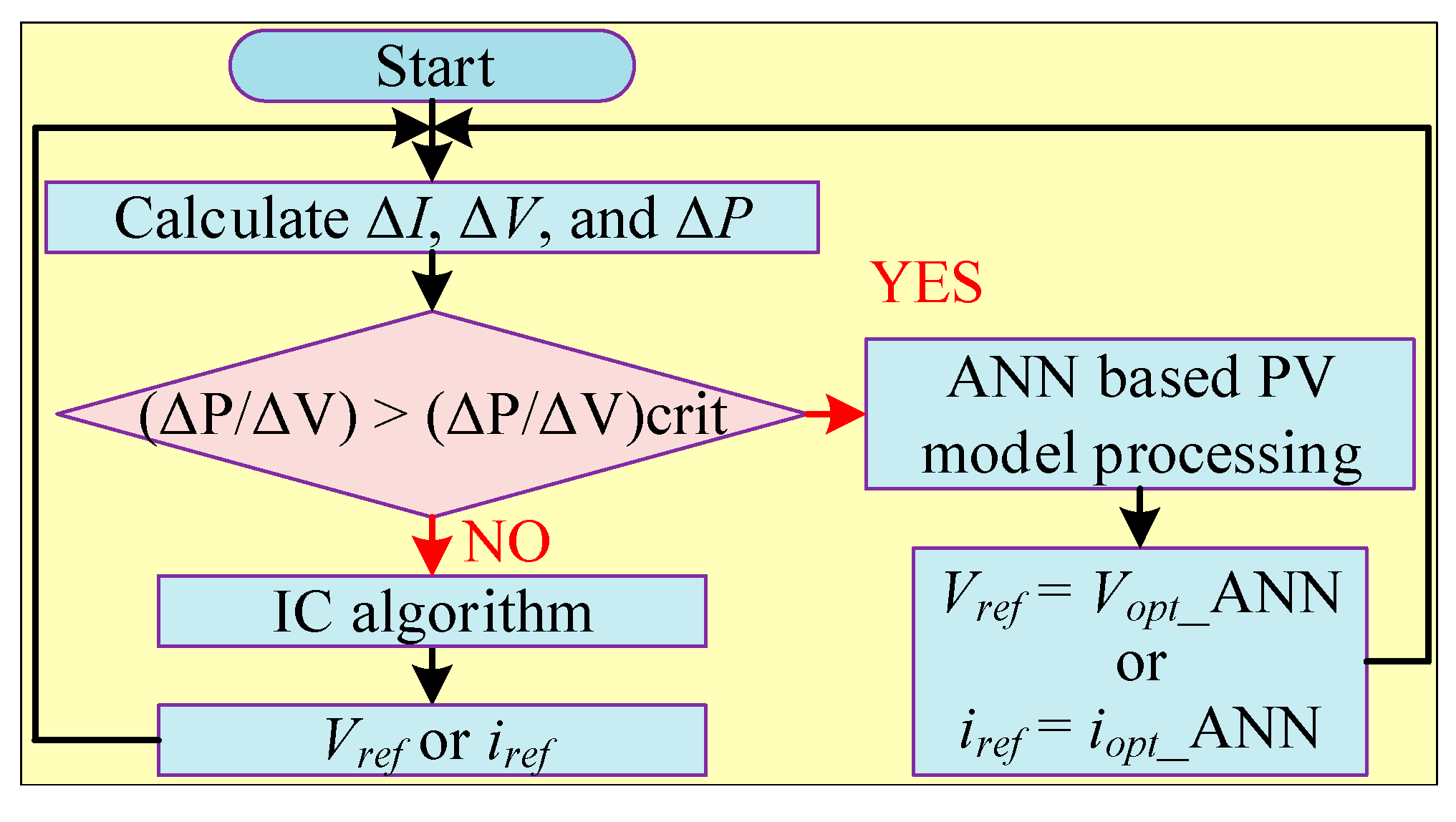
2.3.25. ANN with IC
2.3.26. ANFIS with P and O
2.3.27. FLC with Angle of Incremental Conductance
2.3.28. FLC with HC
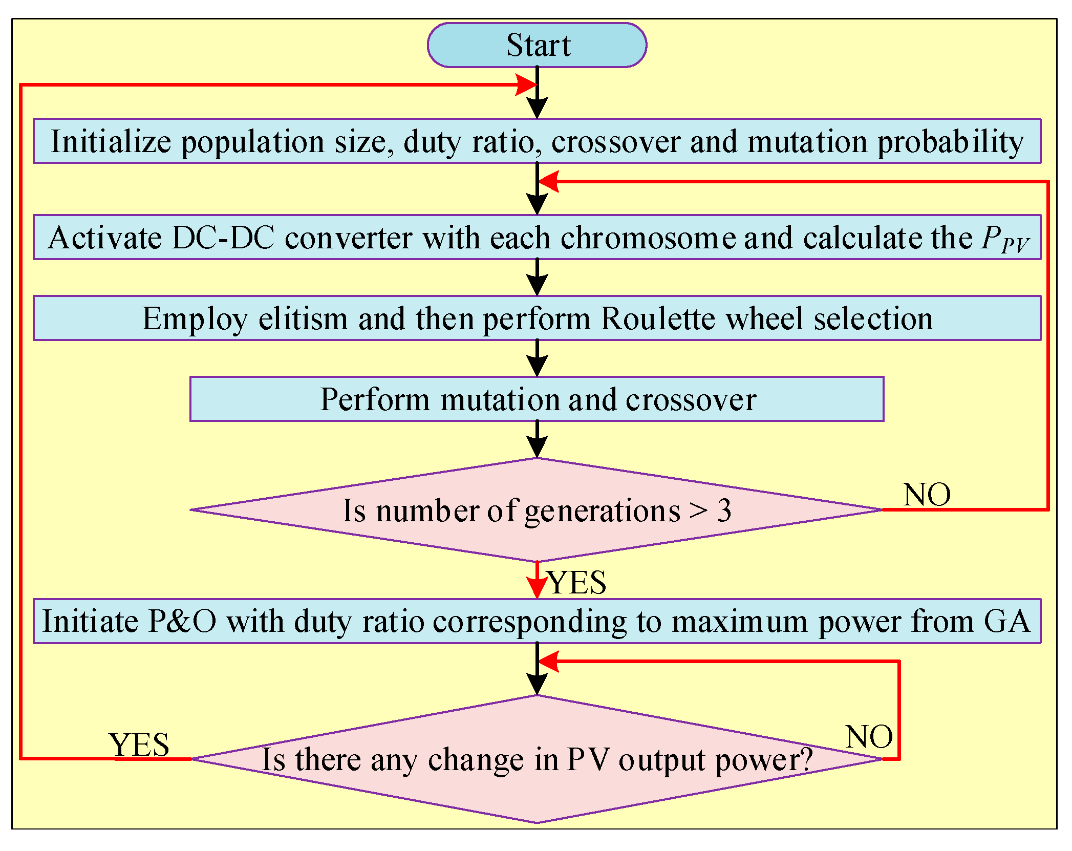
2.3.29. GA with P and O
2.3.30. Modified FOCV with Current Sensor-Less Auto Modulation
2.3.31. Improved Open Circuit Voltage with Smart Power Scanning
2.3.32. ABC with HC
2.3.33. ABC with P and O
3. Performance Evaluation Parameters and Comparative Analysis
3.1. Tracking Accuracy
3.2. Implementation Complexity
3.3. Tracking Speed
3.4. Steady-State Oscillation
3.5. Power Conversion Efficiency
3.6. Sensors
3.7. DC–DC Converter Selection
3.8. Cost
3.9. PSCs Handling
3.10. PV Module Connections
3.11. Location and Seasons
| Ref. | Year | Algorithm | C | S.U. | T.A. | T.S. | O.L. | PV.M.D. | E.V. | C.T. | Cost | η |
|---|---|---|---|---|---|---|---|---|---|---|---|---|
| Combination of Conventional Algorithms | ||||||||||||
| [42] | 2017 | P and O-FSCC | L | V, I, T | M | L | H | No | No | Buck Boost | H | M |
| [44] | 2016 | FSCC-IC | L | I, V | M | L | L | Yes | No | N.G. | L | M |
| [46] | 2016 | FOCV-P and O | L | I, V | M | L | M | Yes | Yes | Buck | L | M |
| [47] | 2016 | FOCV-IC | L | I, V | M | L | L | Yes | No | Boost | L | M |
| [48] | 2017 | P and O-IC | M | V, I | M | M | M | No | Yes | Boost | H | M |
| [49] | 2008 | MP and O-MP and O | M | V, I | M | M | M | No | Yes | Boost | H | M |
| [51] | 2014 | EPP-IC | M | V, I | M | M | L | No | No | Boost | M | M |
| Combination of Soft Computing Algorithms | ||||||||||||
| [12] | 2017 | WO-DE | H | I, V | H | H | M | Yes | No | N.G. | H | H |
| [25] | 2020 | GWO-CSA | H | I, V | H | H | L | No | No | Buck-Boost | H | VH |
| [52] | 2021 | PSO-DE | H | I, V | VH | VH | L | No | No | SEPIC | H | VH |
| [54] | 2013 | PSO-PI | H | V, I | H | H | L | No | Yes | NG | H | H |
| [55] | 2018 | PSO-OD | H | V, I | H | VH | L | No | Yes | Boost | H | VH |
| [56] | 2019 | PSO-ANFIS | H | V, I | V.H | V.H | L | No | Yes | Zeta | H | VH |
| [57] | 2018 | PSO-OCC | H | I | H | H | L | Yes | No | Boost | H | H |
| [60] | 2017 | PSO-EL | H | V, I | VH | VH | L | No | No | Boost | H | VH |
| [61] | 2017 | PSO-SA | H | V, I | H | V.H | L | No | No | NG | H | VH |
| [62] | 2021 | PSO-LFO | H | V, I | V.H | V.H | L | No | Yes | Boost | H | VH |
| [63] | 2015 | PSO-FLC | H | V, I | VH | H | L | No | Yes | Boost | H | VH |
| [64] | 2020 | PSO-TSMC | H | V, I | VH | VH | L | No | No | NG | H | VH |
| [65] | 2013 | PSO-GSA | H | I, V | H | L | H | No | No | Boost | H | H |
| [66] | 2011 | ANN-PSO | VH | V, I | V.H | H | VL | No | No | Boost | VH | H |
| [67] | 2017 | PSO-SFLA | H | I, V, P | H | H | L | No | No | Boost | H | H |
| [68] | 2018 | MPV-PSO | H | V, I | H | H | L | No | Yes | Boost | VH | H |
| [69] | 2019 | ISSA-PSO | H | V, I | VH | V.H. | VL | No | No | NG | VH | VH |
| [70] | 2019 | SSA-GWO | H | V, I | VH | V.H. | VL | No | No | Buck Boost | H | VH |
| [71] | 2022 | TSA-PSO | VH | V, I | VH | H | VL | No | Yes | Boost | VH | H |
| [72] | 2017 | PSOEM-FSA | VH | V, I | H | VH | L | No | Yes | Interleaved Boost | VH | VH |
| [74] | 2020 | FFA | H | I, V | V.H. | V.H. | L | No | Yes | Interleaved Boost | H | VH |
| [75] | 2016 | FA-FLC | H | I, V | H | H | L | Yes | No | Boost | H | H |
| [76] | 2019 | ACSA | M | I, V | M | H | L | Yes | No | Boost | M | H |
| [77] | 2019 | CSA-GSS | V.H. | V, I | V.H. | V.H. | L | No | Yes | N.G. | H | VH |
| [79] | 2018 | RQGPR trained ANN | VH | V, I | VH | VH | L | No | No | Cuk | H | VH |
| [79] | 2018 | CGSVM trained ANN | VH | V, I | VH | VH | L | No | Yes | Cuk | H | VH |
| [80] | 2018 | FPSOGSA-trained ANN | VH | V, I | VH | VH | VL | No | Yes | Boost | VH | VH |
| [81] | 2022 | GS-PS trained ANN | VH | V, I, G, T | VH | VH | VL | No | No | Buck | VH | VH |
| [82] | 2016 | ANN-GA | VH | V, I | VH | H | VL | No | No | NG | VH | H |
| [83] | 2018 | ANFIS | H | V, I, P | H | H | L | No | Yes | Buck | H | VH |
| [84] | 2017 | ANN-SP | H | I, V, G | H | M | L | Yes | No | Boost | H | H |
| [85] | 2022 | ANN-ACO | VH | V, I | VH | V.H. | L | No | Yes | Boost | H | VH |
| [86] | 2019 | ANN-MC | VH | I, V | H | H | L | No | No | NG | VH | H |
| [87] | 2018 | ANN vision-BS | VH | V, I | VH | VH | VL | No | Yes | Buck Boost | VH | VH |
| [88] | 2020 | IANN-PSO | H | I, V | VH | VH | L | No | No | NG | H | VH |
| [89] | 2019 | RBFNN-PSO | VH | I, V | VH | VH | L | No | Yes | Boost | H | VH |
| [90] | 2021 | RBFNN-BTSMC | VH | G, T | VH | V.H. | VL | No | No | Buck Boost | VH | VH |
| [92] | 2018 | GWO-Beta | VH | V, I | VH | VH | VL | No | Yes | Boost | H | VH |
| [93] | 2019 | GWO-FLC | H | I, V | VH | VH | L | No | No | Boost | H | VH |
| [94] | 2018 | GWO-GSO | VH | V, I | H | V.H. | L | No | Yes | Boost | H | VH |
| [95] | 2021 | ANFIS-CPHO | VH | V, I | VH | VH | VL | No | No | Boost | H | VH |
| [96] | 2020 | MSFLA-FLC | VH | V, I, P | VH | VH | L | No | No | NG | VH | VH |
| [97] | 2019 | Beta-FLC | H | I, V | H | H | VL | No | Yes | Boost | H | H |
| [99] | 2011 | FLC-GA | VH | I, V | VH | VH | L | No | Yes | Boost | H | VH |
| [100] | 2019 | PI-FLC | H | I, V | H | VH | L | No | No | Boost | H | H |
| [101] | 2019 | TLBO-FLC | H | V, I | H | H | L | No | Yes | Boost | H | H |
| [103] | 2018 | HTGA | VH | V, I, P | VH | H | M | Yes | No | Buck | H | VH |
| [104] | 2018 | GA + FA and DE | M | I, V | M | H | L | Yes | Yes | Buck | H | VH |
| [105] | 2021 | GA + ACO | H | V, I | H | H | L | No | No | Boost | VH | VH |
| [106] | 2020 | DM-Jaya | H | V, I | H | H | L | No | Yes | Boost | H | VH |
| [107] | 2017 | Jaya-DE | H | I, V, D | VH | VH | L | No | Yes | Boost | H | VH |
| [108] | 2013 | E and R | M | V, I | H | M | L | Yes | No | NG | M | M |
| [110] | 2018 | DLCI | VH | V, I | V.H. | V.H. | L | No | Yes | N.G. | VH | VH |
| [111] | 2017 | CGSCO | VH | I | VH | VH | L | No | Yes | Boost | VH | VH |
| Combination of Conventional with Soft Computing Algorithms | ||||||||||||
| [13] | 2019 | IP and O-ABC | M | I, V | VH | H | L | No | Yes | Boost | H | VH |
| [46] | 2016 | P and O-PInc | M | V, I | M | L | M | No | Yes | Buck | M | M |
| [112] | 2016 | P and O-PSO | H | I, V | V.H. | V.H. | L | No | Yes | Boost | H | H |
| [113] | 2017 | P and O-IPSO | H | V, I | H | V.H. | L | No | Yes | Buck Boost | H | VH |
| [114] | 2018 | P and O-FLC | M | I, V | H | M | L | No | No | Boost | M | H |
| [115] | 2021 | P and O-SSA | H | V, I | H | H | L | No | Yes | Boost | H | VH |
| [116] | 2016 | P and O-GWO | H | I, V | V.H. | V.H. | L | No | Yes | Boost | M | VH |
| [117] | 2019 | P and O-AIDSM | VH | I, V | H | VH | L | No | Yes | Boost | VH | VH |
| [118] | 2016 | P and O-FWA | H | I, V | H | H | M | Yes | Yes | Boost | H | H |
| [119] | 2015 | P and O-ACO | H | I, V | VH | VH | L | No | Yes | Boost | H | VH |
| [120] | 2021 | AIAPO | H | V, I | H | H | L | No | No | Boost | VH | VH |
| [121] | 2015 | AP and O-FLC | M | I, V | M | M | L | Yes | Yes | Cuk | M | M |
| [122] | 2016 | GSA-P and O | H | V, I | H | H | L | No | Yes | Boost | H | H |
| [123] | 2021 | SPF-P and O | H | V, I | H | H | VL | No | Yes | Boost | VH | H |
| [124] | 2015 | SA-P and O | H | V, I | H | H | L | No | No | NG | H | VH |
| [125] | 2018 | SAPSO-HC | H | I, V | VH | H | L | No | Yes | Buck | H | H |
| [126] | 2014 | IC-FLC | M | V, I | M | M | M | No | No | Cuk | M | M |
| [127] | 2016 | IC-FA | H | I, V | H | H | M | Yes | No | Boost | H | H |
| [128] | 2020 | IC-GOA | H | V, I | V.H. | V.H. | L | Yes | Yes | Interleaved Boost | H | VH |
| [129] | 2019 | IC-MFO | M | V, I | H | M | M | Yes | No | Boost | M | M |
| [130] | 2020 | PCPIO-IC | H | V, I | VH | H | VL | No | No | Boost | VH | VH |
| [131] | 2014 | IC-PSO | H | I, V | VH | H | L | No | No | NG | H | H |
| [132] | 2022 | IC-DFO | H | V, I | H | H | L | No | No | Boost | H | VH |
| [133] | 2012 | Pinc-IC | M | V, I | M | M | L | Yes | Yes | Fly back | L | M |
| [136] | 2014 | ANN-P and O | H | V, I | VH | H | L | No | Yes | Buck Boost | VH | H |
| [137] | 2010 | ANN-IC | H | I | M | H | L | No | No | Boost | H | H |
| [138] | 2020 | FA-ANFIS-P and O | VH | V, I, G | VH | VH | VL | No | No | Buck Boost | VH | VH |
| [139] | 2020 | AIC-FLC | H | I, V | M | H | L | Yes | Yes | Boost | H | VH |
| [140] | 2010 | HC-FLC | M | I, V | M | H | L | No | No | Boost | M | M |
| [141] | 2015 | P and O-GA | H | I, V | H | H | L | No | Yes | Boost | VH | H |
| [142] | 2016 | MFOCV-CSAM | H | V, I | H | VH | L | No | Yes | Boost | M | H |
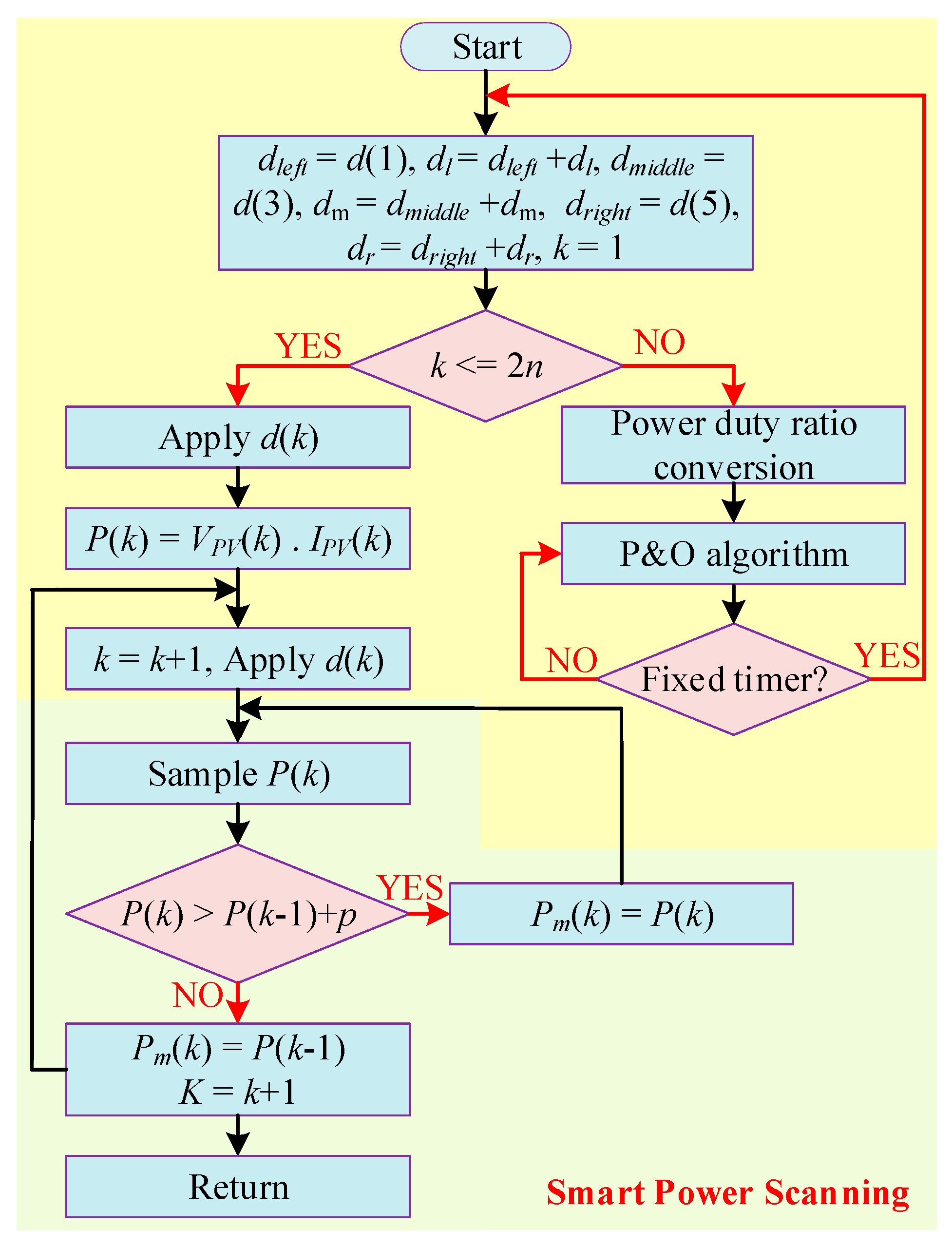
| [143] | 2018 | IOCV-SPS | M | I, V | M | H | L | No | Yes | SEPIC | M | H |
| [146] | 2018 | ABC-HC | VH | I, V | H | H | L | No | Yes | Boost | H | H |
| [147] | 2021 | ABC-P and O | M | V, I | V.H | V.H | L | Yes | Yes | Boost | VH | VH |
4. Conclusions and Future Work
Author Contributions
Funding
Data Availability Statement
Conflicts of Interest
References
- Khan, M.Y.A.; Liu, H.; Alhani, E.; Karim, H. Design of a phase disposition PWM technique for reduced switch asymmetric 31-level inverter. In Proceedings of the 2021 International Conference on Computing, Electronic and Electrical Engineering (ICE Cube), Quetta, Pakistan, 26–27 October A2021; pp. 1–10. [Google Scholar]
- Gibb, D.; Ledanois, N.; Ranalder, L.; Yaqoob, H.; Murdock, H.E.; Achury, N.; Andre, T.; Benachir, I.; Dhar, A.; Gicquel, S. Renewables 2022 global status report+ Renewable energy data in perspective+ Press releases+ Regional fact sheets+ Country fact sheets. In Energy Planning, Policy and Economy; IEAE: Paris, France, 2022. [Google Scholar]
- Ali Khan, M.Y.; Liu, H.; Yang, Z.; Yuan, X. A comprehensive review on grid connected photovoltaic inverters, their modulation techniques, and control strategies. Energies 2020, 13, 4185. [Google Scholar] [CrossRef]
- Priyadarshi, N.; Bhaskar, M.; Sanjeevikumar, P.; Azam, F.; Khan, B. High-power DC-DC converter with proposed HSFNA MPPT for photovoltaic based ultra-fast charging system of electric vehicles. IET Renew. Power Gener. 2022, 1–13. [Google Scholar] [CrossRef]
- Alik, R.; Jusoh, A. An enhanced P&O checking algorithm MPPT for high tracking efficiency of partially shaded PV module. Sol. Energy 2018, 163, 570–580. [Google Scholar]
- Xiao, W.; Dunford, W.G. A modified adaptive hill climbing MPPT method for photovoltaic power systems. In Proceedings of the 2004 IEEE 35th Annual Power Electronics Specialists Conference, (IEEE Cat. No. 04CH37551), Aachen, Germany, 20–25 June 2004; pp. 1957–1963. [Google Scholar]
- Belhachat, F.; Larbes, C. Global maximum power point tracking based on ANFIS approach for PV array configurations under partial shading conditions. Renew. Sustain. Energy Rev. 2017, 77, 875–889. [Google Scholar] [CrossRef]
- Khan, M.Y.A.; Liu, H.; Hashemzadeh, S.M.; Yuan, X. A novel high step-up DC–DC converter with improved P&O MPPT for photovoltaic applications. Electr. Power Compon. Syst. 2021, 49, 884–900. [Google Scholar]
- Loukriz, A.; Haddadi, M.; Messalti, S. Simulation and experimental design of a new advanced variable step size Incremental Conductance MPPT algorithm for PV systems. ISA Trans. 2016, 62, 30–38. [Google Scholar] [CrossRef] [PubMed]
- Yunliang, W.; Nan, B. Research of MPPT control method based on PSO algorithm. In Proceedings of the 2015 4th International Conference on Computer Science and Network Technology (ICCSNT), Harbin, China, 19–20 December 2015; pp. 698–701. [Google Scholar]
- Pervez, I.; Sarwar, A.; Tayyab, M.; Sarfraz, M. Gravitational search algorithm (GSA) based maximum power point tracking in a solar PV based generation system. In Proceedings of the 2019 Innovations in Power and Advanced Computing Technologies (i-PACT), Vellore, India, 22–23 March 2019; pp. 1–6. [Google Scholar]
- Kumar, N.; Hussain, I.; Singh, B.; Panigrahi, B.K. MPPT in dynamic condition of partially shaded PV system by using WODE technique. IEEE Trans. Sustain. Energy 2017, 8, 1204–1214. [Google Scholar] [CrossRef]
- Pilakkat, D.; Kanthalakshmi, S. An improved P&O algorithm integrated with artificial bee colony for photovoltaic systems under partial shading conditions. Sol. Energy 2019, 178, 37–47. [Google Scholar]
- Fitriyah, F.; Efendi, M.Z.; Murdianto, F.D. Modeling and simulation of MPPT zeta converter using human psychology optimization algorithm under partial shading condition. In Proceedings of the 2020 International Electronics Symposium (IES), Cagliari, Italy, 20–22 April 2020; pp. 14–20. [Google Scholar]
- Rao, R. Jaya: A simple and new optimization algorithm for solving constrained and unconstrained optimization problems. Int. J. Ind. Eng. Comput. 2016, 7, 19–34. [Google Scholar]
- Baimel, D.; Tapuchi, S.; Bronshtein, S.; Horen, Y.; Baimel, N. Novel segmentation algorithm for maximum power point tracking in pv systems under partial shading conditions. In Proceedings of the 2018 IEEE 18th International Power Electronics and Motion Control Conference (PEMC), Budapest, Hungary, 26–30 August 2018; pp. 406–410. [Google Scholar]
- Li, X.; Wen, H.; Hu, Y.; Jiang, L.; Xiao, W. Modified beta algorithm for GMPPT and partial shading detection in photovoltaic systems. IEEE Trans. Power Electron. 2017, 33, 2172–2186. [Google Scholar] [CrossRef]
- Guruambeth, R.; Ramabadran, R. Fuzzy logic controller for partial shaded photovoltaic array fed modular multilevel converter. IET Power Electron. 2016, 9, 1694–1702. [Google Scholar] [CrossRef]
- Elobaid, L.M.; Abdelsalam, A.K.; Zakzouk, E.E. Artificial neural network-based photovoltaic maximum power point tracking techniques: A survey. IET Renew. Power Gener. 2015, 9, 1043–1063. [Google Scholar] [CrossRef]
- Dhivya, P.; Kumar, K.R. MPPT based control of sepic converter using firefly algorithm for solar PV system under partial shaded conditions. In Proceedings of the 2017 International Conference on Innovations in Green Energy and Healthcare Technologies (IGEHT), Coimbatore, India, 16–18 March 2017; pp. 1–8. [Google Scholar]
- Eltamaly, A.M. An improved cuckoo search algorithm for maximum power point tracking of photovoltaic systems under partial shading conditions. Energies 2021, 14, 953. [Google Scholar] [CrossRef]
- Sridhar, R.; Subramani, C.; Pathy, S. A grasshopper optimization algorithm aided maximum power point tracking for partially shaded photovoltaic systems. Comput. Electr. Eng. 2021, 92, 107124. [Google Scholar] [CrossRef]
- Kishore, D.K.; Mohamed, M.; Sudhakar, K.; Peddakapu, K. Swarm intelligence-based MPPT design for PV systems under diverse partial shading conditions. Energy 2023, 265, 126366. [Google Scholar] [CrossRef]
- Zhou, L.; Chen, Y.; Guo, K.; Jia, F. New approach for MPPT control of photovoltaic system with mutative-scale dual-carrier chaotic search. IEEE Trans. Power Electron. 2010, 26, 1038–1048. [Google Scholar] [CrossRef]
- Davoodkhani, F.; Arabi Nowdeh, S.; Abdelaziz, A.Y.; Mansoori, S.; Nasri, S.; Alijani, M. A new hybrid method based on gray wolf optimizer-crow search algorithm for maximum power point tracking of photovoltaic energy system. In Modern Maximum Power Point Tracking Techniques for Photovoltaic Energy Systems; Springer: Berlin/Heidelberg, Germany, 2020; pp. 421–438. [Google Scholar]
- Batarseh, M.G.; Za’ter, M.E. Hybrid maximum power point tracking techniques: A comparative survey, suggested classification and uninvestigated combinations. Sol. Energy 2018, 169, 535–555. [Google Scholar] [CrossRef]
- Yang, B.; Zhu, T.; Wang, J.; Shu, H.; Yu, T.; Zhang, X.; Yao, W.; Sun, L. Comprehensive overview of maximum power point tracking algorithms of PV systems under partial shading condition. J. Clean. Prod. 2020, 268, 121983. [Google Scholar] [CrossRef]
- Ali, A.; Almutairi, K.; Padmanaban, S.; Tirth, V.; Algarni, S.; Irshad, K.; Islam, S.; Zahir, M.H.; Shafiullah, M.; Malik, M.Z. Investigation of MPPT techniques under uniform and non-uniform solar irradiation condition–a retrospection. IEEE Access 2020, 8, 127368–127392. [Google Scholar] [CrossRef]
- Wasim, M.S.; Amjad, M.; Habib, S.; Abbasi, M.A.; Bhatti, A.R.; Muyeen, S. A critical review and performance comparisons of swarm-based optimization algorithms in maximum power point tracking of photovoltaic systems under partial shading conditions. Energy Rep. 2022, 8, 4871–4898. [Google Scholar] [CrossRef]
- Ali, A.; Almutairi, K.; Malik, M.Z.; Irshad, K.; Tirth, V.; Algarni, S.; Zahir, M.H.; Islam, S.; Shafiullah, M.; Shukla, N.K. Review of online and soft computing maximum power point tracking techniques under non-uniform solar irradiation conditions. Energies 2020, 13, 3256. [Google Scholar] [CrossRef]
- Jalil, M.F.; Khatoon, S.; Nasiruddin, I.; Bansal, R. Review of PV array modelling, configuration and MPPT techniques. Int. J. Model. Simul. 2022, 42, 533–550. [Google Scholar] [CrossRef]
- Sarvi, M.; Azadian, A. A comprehensive review and classified comparison of MPPT algorithms in PV systems. Energy Syst. 2022, 13, 281–320. [Google Scholar] [CrossRef]
- Hanzaei, S.H.; Gorji, S.A.; Ektesabi, M. A scheme-based review of MPPT techniques with respect to input variables including solar irradiance and PV arrays’ temperature. IEEE Access 2020, 8, 182229–182239. [Google Scholar] [CrossRef]
- Omar, F.A.; Pamuk, N.; KULAKSIZ, A.A. A critical evaluation of maximum power point tracking techniques for PV systems working under partial shading conditions. Turk. J. Eng. 2023, 7, 73–81. [Google Scholar] [CrossRef]
- Verma, P.; Alam, A.; Sarwar, A.; Tariq, M.; Vahedi, H.; Gupta, D.; Ahmad, S.; Shah Noor Mohamed, A. Meta-heuristic optimization techniques used for maximum power point tracking in solar pv system. Electronics 2021, 10, 2419. [Google Scholar] [CrossRef]
- Bollipo, R.B.; Mikkili, S.; Bonthagorla, P.K. Critical review on PV MPPT techniques: Classical, intelligent and optimisation. IET Renew. Power Gener. 2020, 14, 1433–1452. [Google Scholar] [CrossRef]
- Baba, A.O.; Liu, G.; Chen, X. Classification and evaluation review of maximum power point tracking methods. Sustain. Futures 2020, 2, 100020. [Google Scholar] [CrossRef]
- Naseem, M.; Husain, M.A.; Minai, A.F.; Khan, A.N.; Amir, M.; Dinesh Kumar, J.; Iqbal, A. Assessment of meta-heuristic and classical methods for GMPPT of PV system. Trans. Electr. Electron. Mater. 2021, 22, 217–234. [Google Scholar] [CrossRef]
- Alrubaie, A.J.; Al-Khaykan, A.; Malik, R.; Talib, S.H.; Mousa, M.I.; Kadhim, A.M. Review on MPPT techniques in solar system. In Proceedings of the 2022 8th International Engineering Conference on Sustainable Technology and Development (IEC), Erbil, Iraq, 23–24 February 2022; pp. 123–128. [Google Scholar]
- Raj, S.A.; Samuel, G.G. Survey of AI based MPPT algorithms in PV systems. In Proceedings of the 2022 4th International Conference on Smart Systems and Inventive Technology (ICSSIT), Tirunelveli, India, 20–22 January 2022; pp. 597–604. [Google Scholar]
- Sandali, A.; Oukhoya, T.; Cheriti, A. Modeling and design of PV grid connected system using a modified fractional short-circuit current MPPT. In Proceedings of the 2014 International Renewable and Sustainable Energy Conference (IRSEC), Ouarzazate, Morocco, 17–19 October 2014; pp. 224–229. [Google Scholar]
- Sher, H.A.; Murtaza, A.F.; Al-Haddad, K. In A hybrid maximum power point tracking method for photovoltaic applications with reduced offline measurements. In Proceedings of the 2017 IEEE International Conference on Industrial Technology (ICIT), Toronto, ON, Canada, 22–25 March 2017; pp. 1482–1485. [Google Scholar]
- Penella, M.T.; Gasulla, M. A simple and efficient MPPT method for low-power PV cells. Int. J. Photoenergy 2014, 2014, 153428. [Google Scholar] [CrossRef] [Green Version]
- Labeeb, K.; Shankar, S.; Ramprabhakar, J. Hybrid MPPT controller for accurate and quick tracking. In Proceedings of the 2016 IEEE International Conference on Recent Trends in Electronics, Information & Communication Technology (RTEICT), Bangalore, India, 20–21 May 2016; pp. 1533–1537. [Google Scholar]
- Soualmia, A.; Chenni, R. A survey of maximum peak power tracking techniques used in photovoltaic power systems. In Proceedings of the 2016 Future Technologies Conference (FTC), San Francisco, CA, USA, 6–7 December 2016; pp. 430–443. [Google Scholar]
- Al-Soeidat, M.R.; Cembrano, A.; Lu, D.D. Comparing effectiveness of hybrid mppt algorithms under partial shading conditions. In Proceedings of the 2016 IEEE International Conference on Power System Technology (POWERCON), Wollongong, NSW, Australia, 28 September–1 October 2016; pp. 1–6. [Google Scholar]
- Javed, M.Y.; Gulzar, M.M.; Rizvi, S.T.H.; Arif, A. A hybrid technique to harvest maximum power from PV systems under partial shading conditions. In Proceedings of the 2016 International Conference on Emerging Technologies (ICET), Islamabad, Pakistan, 18–19 October 2016; pp. 1–5. [Google Scholar]
- Yüksek, G.; Mete, A.N. A hybrid variable step size MPPT method based on P&O and INC methods. In Proceedings of the 2017 10th International Conference on Electrical and Electronics Engineering (ELECO), Bursa, Turkey, 30 November–2 December 2017; pp. 949–953. [Google Scholar]
- Patel, H.; Agarwal, V. Maximum power point tracking scheme for PV systems operating under partially shaded conditions. IEEE Trans. Ind. Electron. 2008, 55, 1689–1698. [Google Scholar] [CrossRef]
- Ansari, F.; Chatterji, S.; Iqbal, A.; Afzal, A. Control of MPPT for photovoltaic systems using advanced algorithm EPP. In Proceedings of the 2009 International Conference on Power Systems, Kharagpur, India, 27–29 December 2009; pp. 1–6. [Google Scholar]
- Rout, A.; Samantara, S.; Dash, G.; Choudhury, S.; Sharma, R.; Dash, B. Modeling and simulation of hybrid MPPT based standalone PV system with upgraded multilevel inverter. In Proceedings of the 2014 Annual IEEE India Conference (INDICON), Pune, India, 11–13 December 2014; pp. 1–6. [Google Scholar]
- Ahmad, M.S.; Ahmad, A. Hybrid pso-de technique to optimize energy resource for pv system. Int. J. Electr. Eng. Technol. IJEET 2021, 12, 128–139. [Google Scholar]
- Seyedmahmoudian, M.; Rahmani, R.; Mekhilef, S.; Oo, A.M.T.; Stojcevski, A.; Soon, T.K.; Ghandhari, A.S. Simulation and hardware implementation of new maximum power point tracking technique for partially shaded PV system using hybrid DEPSO method. IEEE Trans. Sustain. Energy 2015, 6, 850–862. [Google Scholar] [CrossRef]
- Phimmasone, V.; Kondo, Y.; Shiota, N.; Miyatake, M. The effectiveness evaluation of the newly improved pso-based mppt controlling multiple PV arrays. In Proceedings of the 2013 1st International Future Energy Electronics Conference (IFEEC), Tainan, Taiwan, 3–6 November 2013; pp. 81–86. [Google Scholar]
- Li, H.; Yang, D.; Su, W.; Lü, J.; Yu, X. An overall distribution particle swarm optimization MPPT algorithm for photovoltaic system under partial shading. IEEE Trans. Ind. Electron. 2018, 66, 265–275. [Google Scholar] [CrossRef]
- Priyadarshi, N.; Padmanaban, S.; Holm-Nielsen, J.B.; Blaabjerg, F.; Bhaskar, M.S. An experimental estimation of hybrid ANFIS–PSO-based MPPT for PV grid integration under fluctuating sun irradiance. IEEE Syst. J. 2019, 14, 1218–1229. [Google Scholar] [CrossRef]
- Anoop, K.; Nandakumar, M. A novel maximum power point tracking method based on particle swarm optimization combined with one cycle control. In Proceedings of the 2018 International Conference on Power, Instrumentation, Control and Computing (PICC), Thrissur, India, 18–20 January 2018; pp. 1–6. [Google Scholar]
- Anoop, K.; Nandakumar, M. A Novel control strategy for power extraction from Photo Voltaic panels based on One Cycle Control. In Proceedings of the 2014 IEEE 6th India International Conference on Power Electronics (IICPE), Kurukshetra, India, 8–10 December 2014; pp. 1–6. [Google Scholar]
- Ram, J.P.; Rajasekar, N.; Miyatake, M. Design and overview of maximum power point tracking techniques in wind and solar photovoltaic systems: A review. Renew. Sustain. Energy Rev. 2017, 73, 1138–1159. [Google Scholar] [CrossRef]
- Gavhane, P.S.; Krishnamurthy, S.; Dixit, R.; Ram, J.P.; Rajasekar, N. EL-PSO based MPPT for solar PV under partial shaded condition. Energy Procedia 2017, 117, 1047–1053. [Google Scholar] [CrossRef]
- Guan, T.; Zhuo, F. An improved SA-PSO global maximum power point tracking method of photovoltaic system under partial shading conditions. In Proceedings of the 2017 IEEE International Conference on Environment and Electrical Engineering and 2017 IEEE Industrial and Commercial Power Systems Europe (EEEIC/I&CPS Europe), Milan, Italy, 6–9 June 2017; pp. 1–5. [Google Scholar]
- Charin, C.; Ishak, D.; Zainuri, M.A.A.M.; Ismail, B.; Jamil, M.K.M. A hybrid of bio-inspired algorithm based on Levy flight and particle swarm optimizations for photovoltaic system under partial shading conditions. Sol. Energy 2021, 217, 1–14. [Google Scholar] [CrossRef]
- Cheng, P.-C.; Peng, B.-R.; Liu, Y.-H.; Cheng, Y.-S.; Huang, J.-W. Optimization of a fuzzy-logic-control-based MPPT algorithm using the particle swarm optimization technique. Energies 2015, 8, 5338–5360. [Google Scholar] [CrossRef] [Green Version]
- Lamzouri, F.E.-z.; Boufounas, E.; Brahmi, A.; El Amrani, A. Optimized TSMC control based MPPT for PV system under variable atmospheric conditions using PSO algorithm. Procedia Comput. Sci. 2020, 170, 887–892. [Google Scholar] [CrossRef]
- Dhas, B.G.S.; Deepa, S. A hybrid PSO and GSA-based maximum power point tracking algorithm for PV systems. In Proceedings of the 2013 IEEE International Conference on Computational Intelligence and Computing Research, Enathi, India, 26–28 December 2013; pp. 1–4. [Google Scholar]
- Ngan, M.S.; Tan, C.W. Multiple peaks tracking algorithm using particle swarm optimization incorporated with artificial neural network. Int. J. Electron. Commun. Eng. 2011, 5, 1325–1331. [Google Scholar]
- Mao, M.; Zhang, L.; Duan, Q.; Oghorada, O.; Duan, P.; Hu, B. A two-stage particle swarm optimization algorithm for MPPT of partially shaded PV arrays. Int. J. Green Energy 2017, 14, 694–702. [Google Scholar] [CrossRef]
- Sen, T.; Pragallapati, N.; Agarwal, V.; Kumar, R. Global maximum power point tracking of PV arrays under partial shading conditions using a modified particle velocity-based PSO technique. IET Renew. Power Gener. 2018, 12, 555–564. [Google Scholar] [CrossRef]
- Ibrahim, R.A.; Ewees, A.A.; Oliva, D.; Abd Elaziz, M.; Lu, S. Improved salp swarm algorithm based on particle swarm optimization for feature selection. J. Ambient Intell. Humaniz. Comput. 2019, 10, 3155–3169. [Google Scholar] [CrossRef]
- Wan, Y.; Mao, M.; Zhou, L.; Zhang, Q.; Xi, X.; Zheng, C. A novel nature-inspired maximum power point tracking (MPPT) controller based on SSA-GWO algorithm for partially shaded photovoltaic systems. Electronics 2019, 8, 680. [Google Scholar] [CrossRef] [Green Version]
- Sharma, A.; Sharma, A.; Jately, V.; Averbukh, M.; Rajput, S.; Azzopardi, B. A novel TSA-PSO based hybrid algorithm for GMPP tracking under partial shading conditions. Energies 2022, 15, 3164. [Google Scholar] [CrossRef]
- Mao, M.; Duan, Q.; Duan, P.; Hu, B. Comprehensive improvement of artificial fish swarm algorithm for global MPPT in PV system under partial shading conditions. Trans. Inst. Meas. Control 2018, 40, 2178–2199. [Google Scholar] [CrossRef]
- Nugraha, S.D.; Wahjono, E.; Sunarno, E.; Anggriawan, D.O.; Prasetyono, E.; Tjahjono, A. Maximum power point tracking of photovoltaic module for battery charging based on modified firefly algorithm. In Proceedings of the 2016 International Electronics Symposium (IES), Denpasar, Indonesia, 29–30 September 2016; pp. 238–243. [Google Scholar]
- Huang, Y.-P.; Huang, M.-Y.; Ye, C.-E. A fusion firefly algorithm with simplified propagation for photovoltaic MPPT under partial shading conditions. IEEE Trans. Sustain. Energy 2020, 11, 2641–2652. [Google Scholar] [CrossRef]
- Ajiatmo, D.; Robandi, I. A hybrid Fuzzy Logic Controller-Firefly Algorithm (FLC-FA) based for MPPT Photovoltaic (PV) system in solar car. In Proceedings of the 2016 IEEE International Conference on Power and Renewable Energy (ICPRE), Shanghai, China, 21–23 October 2016; pp. 606–610. [Google Scholar]
- Mirza, A.F.; Ling, Q.; Javed, M.Y.; Mansoor, M. Novel MPPT techniques for photovoltaic systems under uniform irradiance and Partial shading. Sol. Energy 2019, 184, 628–648. [Google Scholar] [CrossRef]
- Nugraha, D.A.; Lian, K.-L. A novel MPPT method based on cuckoo search algorithm and golden section search algorithm for partially shaded PV system. Can. J. Electr. Comput. Eng. 2019, 42, 173–182. [Google Scholar] [CrossRef]
- Kiran, S.R.; Basha, C.H.; Singh, V.P.; Dhanamjayulu, C.; Prusty, B.R.; Khan, B. Reduced simulative performance analysis of variable step size ANN based MPPT techniques for partially shaded solar PV systems. IEEE Access 2022, 10, 48875–48889. [Google Scholar] [CrossRef]
- Farayola, A.M.; Hasan, A.N.; Ali, A. Optimization of PV systems using data mining and regression learner MPPT techniques. Indones. J. Electr. Eng. Comput. Sci. 2018, 10, 1080–1089. [Google Scholar] [CrossRef]
- Duman, S.; Yorukeren, N.; Altas, I.H. A novel MPPT algorithm based on optimized artificial neural network by using FPSOGSA for standalone photovoltaic energy systems. Neural Comput. Appl. 2018, 29, 257–278. [Google Scholar] [CrossRef]
- Alkhalaf, S.; Ali, Z.M.; Oikawa, H. A novel hybrid gravitational and pattern search algorithm based MPPT controller with ANN and perturb and observe for photovoltaic system. Soft Comput. 2022, 26, 7293–7315. [Google Scholar] [CrossRef]
- Prasad, L.B.; Sahu, S.; Gupta, M.; Srivastava, R.; Mozhui, L.; Asthana, D.N. An improved method for MPPT using ANN and GA with maximum power comparison through Perturb & Observe technique. In Proceedings of the 2016 IEEE Uttar Pradesh Section International Conference on Electrical, Computer and Electronics Engineering (UPCON), Varanasi, India, 9–11 December 2016; pp. 206–211. [Google Scholar]
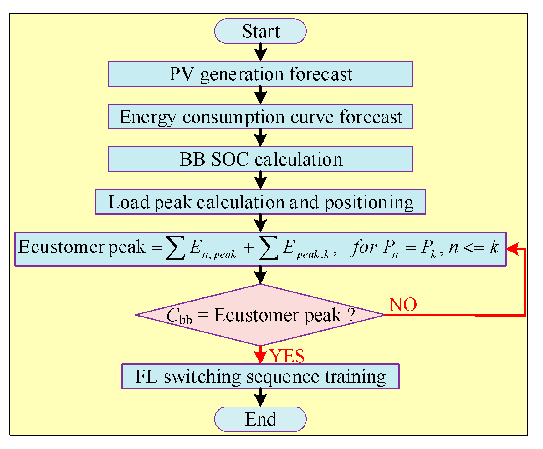
- Nikolovski, S.; Reza Baghaee, H.; Mlakić, D. ANFIS-based peak power shaving/curtailment in microgrids including PV units and BESSs. Energies 2018, 11, 2953. [Google Scholar] [CrossRef] [Green Version]
- Bouselham, L.; Hajji, M.; Hajji, B.; Bouali, H. A new MPPT-based ANN for photovoltaic system under partial shading conditions. Energy Procedia 2017, 111, 924–933. [Google Scholar] [CrossRef]
- Babes, B.; Boutaghane, A.; Hamouda, N. A novel nature-inspired maximum power point tracking (MPPT) controller based on ACO-ANN algorithm for photovoltaic (PV) system fed arc welding machines. Neural Comput. Appl. 2022, 34, 299–317. [Google Scholar] [CrossRef]
- Chen, L.; Wang, X. Enhanced MPPT method based on ANN-assisted sequential Monte–Carlo and quickest change detection. IET Smart Grid 2019, 2, 635–644. [Google Scholar] [CrossRef]
- Martin, A.D.; Vazquez, J.R.; Cano, J. MPPT in PV systems under partial shading conditions using artificial vision. Electr. Power Syst. Res. 2018, 162, 89–98. [Google Scholar] [CrossRef]
- Chouksey, A.; Awasthi, S.; Singh, S.K. Fuzzy cognitive network-based maximum power point tracking using a self-tuned adaptive gain scheduled fuzzy proportional integral derivative controller and improved artificial neural network-based particle swarm optimization. Fuzzy Sets Syst. 2020, 381, 26–50. [Google Scholar] [CrossRef]
- Hamdi, H.; Regaya, C.B.; Zaafouri, A. Real-time study of a photovoltaic system with boost converter using the PSO-RBF neural network algorithms in a MyRio controller. Sol. Energy 2019, 183, 1–16. [Google Scholar] [CrossRef]
- Khan, Z.A.; Khan, L.; Ahmad, S.; Mumtaz, S.; Jafar, M.; Khan, Q. RBF neural network based backstepping terminal sliding mode MPPT control technique for PV system. PLoS ONE 2021, 16, e0249705. [Google Scholar] [CrossRef]
- Tjahjono, A.; Anggriawan, D.O.; Habibi, M.N.; Prasetyono, E. Modified grey wolf optimization for maximum power point tracking in photovoltaic system under partial shading conditions. Int. J. Electr. Eng. Inform. 2020, 12, 94–104. [Google Scholar] [CrossRef]
- Rocha, M.; Sampaio, L.; da Silva, S.O. Maximum power point extraction in PV array under partial shading conditions using GWO-assisted beta method. In Proceedings of the International Conference on Renewable Energies and Power Quality, Madrid, Spain, 24–26 May 2018; pp. 450–455. [Google Scholar]
- Eltamaly, A.M.; Farh, H.M. Dynamic global maximum power point tracking of the PV systems under variant partial shading using hybrid GWO-FLC. Sol. Energy 2019, 177, 306–316. [Google Scholar] [CrossRef]
- Shi, J.-Y.; Zhang, D.-Y.; Ling, L.-T.; Xue, F.; Li, Y.-J.; Qin, Z.-J.; Yang, T. Dual-algorithm maximum power point tracking control method for photovoltaic systems based on grey wolf optimization and golden-section optimization. J. Power Electron. 2018, 18, 841–852. [Google Scholar]
- Pachaivannan, N.; Subburam, R.; Padmanaban, M.; Subramanian, A. Certain investigations of ANFIS assisted CPHO algorithm tuned MPPT controller for PV arrays under partial shading conditions. J. Ambient Intell. Humaniz. Comput. 2021, 12, 9923–9938. [Google Scholar] [CrossRef]
- Li, Y.; Samad, S.; Ahmed, F.W.; Abdulkareem, S.S.; Hao, S.; Rezvani, A. Analysis and enhancement of PV efficiency with hybrid MSFLA–FLC MPPT method under different environmental conditions. J. Clean. Prod. 2020, 271, 122195. [Google Scholar] [CrossRef]
- Li, X.; Wen, H.; Hu, Y.; Jiang, L. A novel beta parameter based fuzzy-logic controller for photovoltaic MPPT application. Renew. Energy 2019, 130, 416–427. [Google Scholar] [CrossRef]
- Messai, A.; Mellit, A.; Guessoum, A.; Kalogirou, S.A. Maximum power point tracking using a GA optimized fuzzy logic controller and its FPGA implementation. Sol. Energy 2011, 85, 265–277. [Google Scholar] [CrossRef]
- Shill, P.C.; Akhand, M.; Murase, K. Simultaneous design of membership functions and rule sets for type-2 fuzzy controllers using genetic algorithms. In Proceedings of the 14th International Conference on Computer and Information Technology (ICCIT 2011), Dhaka, Bangladesh, 22–24 December 2011; pp. 554–559. [Google Scholar]
- Kim, J.-C.; Huh, J.-H.; Ko, J.-S. Improvement of MPPT control performance using fuzzy control and VGPI in the PV system for micro grid. Sustainability 2019, 11, 5891. [Google Scholar] [CrossRef] [Green Version]
- Farajdadian, S.; Hosseini, S.H. Optimization of fuzzy-based MPPT controller via metaheuristic techniques for stand-alone PV systems. Int. J. Hydrogen Energy 2019, 44, 25457–25472. [Google Scholar] [CrossRef]
- Rao, R.V.; Savsani, V.J.; Vakharia, D. Teaching–learning-based optimization: A novel method for constrained mechanical design optimization problems. Comput.-Aided Des. 2011, 43, 303–315. [Google Scholar] [CrossRef]
- Lee, C.-T.; Tsou, H.-I.; Chou, T.-H.; Weng, K.-W. Application of the hybrid Taguchi genetic algorithm to maximum power point tracking of photovoltaic system. In Proceedings of the 2018 IEEE International Conference on Applied System Invention (ICASI), Tokyo, Japan, 13–17 April 2018; pp. 231–234. [Google Scholar]
- Huang, Y.-P.; Chen, X.; Ye, C.-E. A hybrid maximum power point tracking approach for photovoltaic systems under partial shading conditions using a modified genetic algorithm and the firefly algorithm. Int. J. Photoenergy 2018, 2018, 7598653. [Google Scholar] [CrossRef] [Green Version]
- Chao, K.-H.; Rizal, M.N. A hybrid MPPT controller based on the genetic algorithm and ant colony optimization for photovoltaic systems under partially shaded conditions. Energies 2021, 14, 2902. [Google Scholar] [CrossRef]
- Deboucha, H.; Mekhilef, S.; Belaid, S.; Guichi, A. Modified deterministic Jaya (DM-Jaya)-based MPPT algorithm under partially shaded conditions for PV system. IET Power Electron. 2020, 13, 4625–4632. [Google Scholar] [CrossRef]
- Kumar, N.; Hussain, I.; Singh, B.; Panigrahi, B.K. Rapid MPPT for uniformly and partial shaded PV system by using JayaDE algorithm in highly fluctuating atmospheric conditions. IEEE Trans. Ind. Inform. 2017, 13, 2406–2416. [Google Scholar] [CrossRef]
- Ma, J.; Man, K.L.; Ting, T.; Zhang, N.; Lei, C.-U.; Wong, N. A hybrid MPPT method for photovoltaic systems via estimation and revision method. In Proceedings of the 2013 IEEE International Symposium on Circuits and Systems (ISCAS), Beijing, China, 19–23 May 2013; pp. 241–244. [Google Scholar]
- Polak, E. Survey of secant methods for optimization. In Proceedings of the 1973 IEEE Conference on Decision and Control Including the 12th Symposium on Adaptive Processes, San Diego, CA, USA, 5–7 December 1973; p. 416. [Google Scholar]
- Yang, B.; Yu, T.; Zhang, X.; Li, H.; Shu, H.; Sang, Y.; Jiang, L. Dynamic leader based collective intelligence for maximum power point tracking of PV systems affected by partial shading condition. Energy Convers. Manag. 2019, 179, 286–303. [Google Scholar] [CrossRef]
- Kumar, N.; Hussain, I.; Singh, B.; Panigrahi, B.K. Single sensor-based MPPT of partially shaded PV system for battery charging by using cauchy and gaussian sine cosine optimization. IEEE Trans. Energy Convers. 2017, 32, 983–992. [Google Scholar] [CrossRef]
- Manickam, C.; Raman, G.R.; Raman, G.P.; Ganesan, S.I.; Nagamani, C. A hybrid algorithm for tracking of GMPP based on P&O and PSO with reduced power oscillation in string inverters. IEEE Trans. Ind. Electron. 2016, 63, 6097–6106. [Google Scholar]
- Yang, Z.; Duan, Q.; Zhong, J.; Mao, M.; Xun, Z. Analysis of improved PSO and perturb & observe global MPPT algorithm for PV array under partial shading condition. In Proceedings of the 2017 29th Chinese Control And Decision Conference (CCDC), Chongqing, China, 28–30 May 2017; pp. 549–553. [Google Scholar]
- Bataineh, K.; Eid, N. A hybrid maximum power point tracking method for photovoltaic systems for dynamic weather conditions. Resources 2018, 7, 68. [Google Scholar] [CrossRef] [Green Version]
- Premkumar, M.; Kumar, C.; Sowmya, R.; Pradeep, J. A novel salp swarm assisted hybrid maximum power point tracking algorithm for the solar photovoltaic power generation systems. Autom. Časopis Autom. Mjer. Elektron. Računarstvo Komun. 2021, 62, 1–20. [Google Scholar] [CrossRef]
- Mohanty, S.; Subudhi, B.; Ray, P.K. A grey wolf-assisted perturb & observe MPPT algorithm for a PV system. IEEE Trans. Energy Convers. 2016, 32, 340–347. [Google Scholar]
- Kihal, A.; Krim, F.; Laib, A.; Talbi, B.; Afghoul, H. An improved MPPT scheme employing adaptive integral derivative sliding mode control for photovoltaic systems under fast irradiation changes. ISA Trans. 2019, 87, 297–306. [Google Scholar] [CrossRef]
- Manickam, C.; Raman, G.P.; Raman, G.R.; Ganesan, S.I.; Chilakapati, N. Fireworks enriched P&O algorithm for GMPPT and detection of partial shading in PV systems. IEEE Trans. Power Electron. 2016, 32, 4432–4443. [Google Scholar]
- Sundareswaran, K.; Vigneshkumar, V.; Sankar, P.; Simon, S.P.; Nayak, P.S.R.; Palani, S. Development of an improved P&O algorithm assisted through a colony of foraging ants for MPPT in PV system. IEEE Trans. Ind. Inform. 2015, 12, 187–200. [Google Scholar]
- Khan, M.J.; Pushparaj. A novel hybrid maximum power point tracking controller based on artificial intelligence for solar photovoltaic system under variable environmental conditions. J. Electr. Eng. Technol. 2021, 16, 1879–1889. [Google Scholar] [CrossRef]
- Radjai, T.; Gaubert, J.P.; Rahmani, L.; Mekhilef, S. Experimental verification of P&O MPPT algorithm with direct control based on Fuzzy logic control using CUK converter. Int. Trans. Electr. Energy Syst. 2015, 25, 3492–3508. [Google Scholar]
- Sundareswaran, K.; Vigneshkumar, V.; Simon, S.P.; Nayak, P.S.R. Gravitational search algorithm combined with P&O method for MPPT in PV systems. In Proceedings of the 2016 IEEE Annual India Conference (INDICON), Bangalore, India, 16–18 December 2016; pp. 1–5. [Google Scholar]
- González-Castaño, C.; Restrepo, C.; Revelo-Fuelagán, J.; Lorente-Leyva, L.L.; Peluffo-Ordóñez, D.H. A fast-tracking hybrid mppt based on surface-based polynomial fitting and p&o methods for solar pv under partial shaded conditions. Mathematics 2021, 9, 2732. [Google Scholar]
- Lyden, S.; Haque, M. A hybrid simulated annealing and perturb and observe method for maximum power point tracking in PV systems under partial shading conditions. In Proceedings of the 2015 Australasian Universities Power Engineering Conference (AUPEC), Wollongong, Australia, 27–30 September 2015; pp. 1–6. [Google Scholar]
- Chaieb, H.; Sakly, A. A novel MPPT method for photovoltaic application under partial shaded conditions. Sol. Energy 2018, 159, 291–299. [Google Scholar] [CrossRef]
- Radjai, T.; Gaubert, J.P.; Rahmani, L. The new FLC-variable incremental conductance MPPT with direct control method using Cuk converter. In Proceedings of the 2014 IEEE 23rd International Symposium on Industrial Electronics (ISIE), Istanbul, Turkey, 1–4 June 2014; pp. 2508–2513. [Google Scholar]
- Yetayew, T.T.; Jyothsna, T.; Kusuma, G. Evaluation of Incremental conductance and Firefly algorithm for PV MPPT application under partial shade condition. In Proceedings of the 2016 IEEE 6th International Conference on Power Systems (ICPS), New Delhi, India, 4–6 March 2016; pp. 1–6. [Google Scholar]
- Wijaya, B.H.; Subroto, R.K.; Lian, K.L.; Hariyanto, N. A maximum power point tracking method based on a modified grasshopper algorithm combined with incremental conductance. Energies 2020, 13, 4329. [Google Scholar] [CrossRef]
- Rezk, H.; Ali, Z.M.; Abdalla, O.; Younis, O.; Gomaa, M.R.; Hashim, M. Hybrid moth-flame optimization algorithm and incremental conductance for tracking maximum power of solar PV/thermoelectric system under different conditions. Mathematics 2019, 7, 875. [Google Scholar] [CrossRef] [Green Version]
- Tian, A.-Q.; Chu, S.-C.; Pan, J.-S.; Liang, Y. A novel pigeon-inspired optimization based MPPT technique for PV systems. Processes 2020, 8, 356. [Google Scholar] [CrossRef] [Green Version]
- Abdulkadir, M.; Yatim, A.H.M. Hybrid maximum power point tracking technique based on PSO and incremental conductance. In Proceedings of the 2014 IEEE Conference on Energy Conversion (CENCON), Johor Bahru, Malaysia, 13–14 October 2014; pp. 271–276. [Google Scholar]
- Sarwar, S.; Javed, M.Y.; Jaffery, M.H.; Arshad, J.; Ur Rehman, A.; Shafiq, M.; Choi, J.-G. A novel hybrid MPPT technique to maximize power harvesting from pv system under partial and complex partial shading. Appl. Sci. 2022, 12, 587. [Google Scholar] [CrossRef]
- Hsieh, G.-C.; Hsieh, H.-I.; Tsai, C.-Y.; Wang, C.-H. Photovoltaic power-increment-aided incremental-conductance MPPT with two-phased tracking. IEEE Trans. Power Electron. 2012, 28, 2895–2911. [Google Scholar] [CrossRef]
- Hsieh, G.-C.; Chen, H.-L.; Chen, Y.; Tsai, C.-M.; Shyu, S.-S. Variable frequency controlled incremental conductance derived MPPT photovoltaic stand-along DC bus system. In Proceedings of the 2008 Twenty-Third Annual IEEE Applied Power Electronics Conference and Exposition, Austin, TX, USA, 24–28 February 2008; pp. 1849–1854. [Google Scholar]
- Chen, Z.; Yang, P.; Zhou, G.; Xu, J.; Chen, Z. Variable duty cycle control for quadratic boost PFC converter. IEEE Trans. Ind. Electron. 2016, 63, 4222–4232. [Google Scholar] [CrossRef]
- Jiang, L.; Maskell, D.L. A simple hybrid MPPT technique for photovoltaic systems under rapidly changing partial shading conditions. In Proceedings of the 2014 IEEE 40th Photovoltaic Specialist Conference (PVSC), Denver, CO, USA, 8–13 June 2014; pp. 782–787. [Google Scholar]
- Dzung, P.Q.; Lee, H.H.; Vu, N.T.D. The new MPPT algorithm using ANN-based PV. In Proceedings of the International Forum on Strategic Technology 2010, Ulsan, Republic of Korea, 13–15 October 2010; pp. 402–407. [Google Scholar]
- Farzaneh, J. A hybrid modified FA-ANFIS-P&O approach for MPPT in photovoltaic systems under PSCs. Int. J. Electron. 2020, 107, 703–718. [Google Scholar]
- Kececioglu, O.F.; Gani, A.; Sekkeli, M. Design and hardware implementation based on hybrid structure for MPPT of PV system using an interval type-2 TSK fuzzy logic controller. Energies 2020, 13, 1842. [Google Scholar] [CrossRef] [Green Version]
- Alajmi, B.N.; Ahmed, K.H.; Finney, S.J.; Williams, B.W. Fuzzy-logic-control approach of a modified hill-climbing method for maximum power point in microgrid standalone photovoltaic system. IEEE Trans. Power Electron. 2010, 26, 1022–1030. [Google Scholar] [CrossRef]
- Sundareswaran, K.; Vigneshkumar, V.; Palani, S. Development of a hybrid genetic algorithm/perturb and observe algorithm for maximum power point tracking in photovoltaic systems under non-uniform insolation. IET Renew. Power Gener. 2015, 9, 757–765. [Google Scholar] [CrossRef]
- Hua, C.C.; Fang, Y.H.; Chen, W.T. Hybrid maximum power point tracking method with variable step size for photovoltaic systems. IET Renew. Power Gener. 2016, 10, 127–132. [Google Scholar] [CrossRef]
- Başoğlu, M.E.; Çakır, B. Hybrid global maximum power point tracking approach for photovoltaic power optimisers. IET Renew. Power Gener. 2018, 12, 875–882. [Google Scholar] [CrossRef]
- Soufyane Benyoucef, A.; Chouder, A.; Kara, K.; Silvestre, S. Artificial bee colony based algorithm for maximum power point tracking (MPPT) for PV systems operating under partial shaded conditions. Appl. Soft Comput. 2015, 32, 38–48. [Google Scholar] [CrossRef] [Green Version]
- Li, N.; Mingxuan, M.; Yihao, W.; Lichuang, C.; Lin, Z.; Qianjin, Z. Maximum power point tracking control based on modified ABC algorithm for shaded PV system. In Proceedings of the 2019 AEIT International Conference of Electrical and Electronic Technologies for Automotive (AEIT AUTOMOTIVE), Turin, Italy, 2–4 July 2019; pp. 1–5. [Google Scholar]
- Goud, J.S.; Singh, B.; Kumar, S. Maximum power point tracking technique using artificial bee colony and hill climbing algorithms during mismatch insolation conditions on PV array. IET Renew. Power Gener. 2018, 12, 1915–1922. [Google Scholar] [CrossRef]
- Restrepo, C.; Yanẽz-Monsalvez, N.; González-Castaño, C.; Kouro, S.; Rodriguez, J. A fast converging hybrid mppt algorithm based on abc and p&o techniques for a partially shaded pv system. Mathematics 2021, 9, 2228. [Google Scholar]
- Verma, D.; Nema, S.; Shandilya, A.; Dash, S.K. Maximum power point tracking (MPPT) techniques: Recapitulation in solar photovoltaic systems. Renew. Sustain. Energy Rev. 2016, 54, 1018–1034. [Google Scholar] [CrossRef]
- Karami, N.; Moubayed, N.; Outbib, R. General review and classification of different MPPT Techniques. Renew. Sustain. Energy Rev. 2017, 68, 1–18. [Google Scholar] [CrossRef]
- Seyedmahmoudian, M.; Horan, B.; Soon, T.K.; Rahmani, R.; Oo, A.M.T.; Mekhilef, S.; Stojcevski, A. State of the art artificial intelligence-based MPPT techniques for mitigating partial shading effects on PV systems–A review. Renew. Sustain. Energy Rev. 2016, 64, 435–455. [Google Scholar] [CrossRef]
- Messalti, S.; Harrag, A.; Loukriz, A. A new variable step size neural networks MPPT controller: Review, simulation and hardware implementation. Renew. Sustain. Energy Rev. 2017, 68, 221–233. [Google Scholar] [CrossRef]
- Wang, Y.; Li, Y.; Ruan, X. High-accuracy and fast-speed MPPT methods for PV string under partially shaded conditions. IEEE Trans. Ind. Electron. 2015, 63, 235–245. [Google Scholar] [CrossRef]
- Anand, R.; Swaroop, D.; Kumar, B. Global maximum power point tracking for PV array under partial shading using cuckoo search. In Proceedings of the 2020 IEEE 9th Power India International Conference (PIICON), Sonepat, India, 28 February–1 March 2020; pp. 1–6. [Google Scholar]
- Ezinwanne, O.; Zhongwen, F.; Zhijun, L. Energy performance and cost comparison of MPPT techniques for photovoltaics and other applications. Energy Procedia 2017, 107, 297–303. [Google Scholar] [CrossRef]
- Babu, T.S.; Rajasekar, N.; Sangeetha, K. Modified particle swarm optimization technique based maximum power point tracking for uniform and under partial shading condition. Appl. Soft Comput. 2015, 34, 613–624. [Google Scholar] [CrossRef]
- Sher, H.A.; Murtaza, A.F.; Noman, A.; Addoweesh, K.E.; Al-Haddad, K.; Chiaberge, M. A new sensorless hybrid MPPT algorithm based on fractional short-circuit current measurement and P&O MPPT. IEEE Trans. Sustain. Energy 2015, 6, 1426–1434. [Google Scholar]
- Tousi, S.R.; Moradi, M.H.; Basir, N.S.; Nemati, M. A function-based maximum power point tracking method for photovoltaic systems. IEEE Trans. Power Electron. 2015, 31, 2120–2128. [Google Scholar] [CrossRef]
- Husain, M.A.; Tariq, A.; Hameed, S.; Arif, M.S.B.; Jain, A. Comparative assessment of maximum power point tracking procedures for photovoltaic systems. Green Energy Environ. 2017, 2, 5–17. [Google Scholar] [CrossRef]
- Dousoky, G.M.; Shoyama, M. New parameter for current-sensorless MPPT in grid-connected photovoltaic VSIs. Sol. Energy 2017, 143, 113–119. [Google Scholar] [CrossRef]
- Khan, M.Y.A.; Liu, H.; Rehman, N.U. Design of a multiport bidirectional DC-DC converter for low power PV applications. In Proceedings of the 2021 International Conference on Emerging Power Technologies (ICEPT), Topi, Pakistan, 10–11 April 2021; pp. 1–6. [Google Scholar]
- Khan, M.Y.A.; Liu, H.; Habib, S.; Khan, D.; Yuan, X. Design and performance evaluation of a step-up DC–DC converter with dual loop controllers for two stages grid connected PV inverter. Sustainability 2022, 14, 811. [Google Scholar]
- Andrade, A.M.S.S.; Mattos, E.; Schuch, L.; Hey, H.L.; da Silva Martins, M.L. Synthesis and comparative analysis of very high step-up DC–DC converters adopting coupled-inductor and voltage multiplier cells. IEEE Trans. Power Electron. 2017, 33, 5880–5897. [Google Scholar]
- Kumar, A.; Sensarma, P. Ripple-free input current high voltage gain DC–DC converters with coupled inductors. IEEE Trans. Power Electron. 2018, 34, 3418–3428. [Google Scholar] [CrossRef]
- Bao, D.; Kumar, A.; Pan, X.; Xiong, X.; Beig, A.R.; Singh, S.K. Switched inductor double switch high gain DC-DC converter for renewable applications. IEEE Access 2021, 9, 14259–14270. [Google Scholar] [CrossRef]
- Zhang, N.; Zhang, G.; See, K.W.; Zhang, B. A single-switch quadratic buck–boost converter with continuous input port current and continuous output port current. IEEE Trans. Power Electron. 2017, 33, 4157–4166. [Google Scholar] [CrossRef]
- Banaei, M.R.; Sani, S.G. Analysis and implementation of a new SEPIC-based single-switch buck–boost DC–DC converter with continuous input current. IEEE Trans. Power Electron. 2018, 33, 10317–10325. [Google Scholar] [CrossRef]
- Khan, M.Y.A.; Azhar, M.; Saeed, L.; Khan, S.A.; Soomro, J. A High Gain Multiport Non-Isolated DC-DC Converter for PV Applications. In Proceedings of the 2019 2nd International Conference on Computing, Mathematics and Engineering Technologies (iCoMET), Sukkur, Pakistan, 30–31 January 2019; pp. 1–6. [Google Scholar]
- Oluwafemi, A.W.; Ozsoy, E.; Padmanaban, S.; Bhaskar, M.S.; Ramachandaramurthy, V.K.; Fedák, V. A modified high output-gain cuk converter circuit configuration for renewable applications—A comprehensive investigation. In Proceedings of the 2017 IEEE Conference on Energy Conversion (CENCON), Kuala Lumpur, Malaysia, 30–31 October 2017; pp. 117–122. [Google Scholar]
- Padmanaban, S.; Priyadarshi, N.; Bhaskar, M.S.; Holm-Nielsen, J.B.; Ramachandaramurthy, V.K.; Hossain, E. A hybrid ANFIS-ABC based MPPT controller for PV system with anti-islanding grid protection: Experimental realization. IEEE Access 2019, 7, 103377–103389. [Google Scholar] [CrossRef]
- Uno, M.; Kukita, A. Two-switch voltage equalizer using an LLC resonant inverter and voltage multiplier for partially shaded series-connected photovoltaic modules. IEEE Trans. Ind. Appl. 2014, 51, 1587–1601. [Google Scholar] [CrossRef]
- Wang, Y.-J.; Hsu, P.-C. An investigation on partial shading of PV modules with different connection configurations of PV cells. Energy 2011, 36, 3069–3078. [Google Scholar] [CrossRef]
- Gao, L.; Dougal, R.A.; Liu, S.; Iotova, A.P. Parallel-connected solar PV system to address partial and rapidly fluctuating shadow conditions. IEEE Trans. Ind. Electron. 2009, 56, 1548–1556. [Google Scholar]
- Eldin, S.S.; Abd-Elhady, M.; Kandil, H. Feasibility of solar tracking systems for PV panels in hot and cold regions. Renew. Energy 2016, 85, 228–233. [Google Scholar] [CrossRef]


Disclaimer/Publisher’s Note: The statements, opinions and data contained in all publications are solely those of the individual author(s) and contributor(s) and not of MDPI and/or the editor(s). MDPI and/or the editor(s) disclaim responsibility for any injury to people or property resulting from any ideas, methods, instructions or products referred to in the content. |
© 2023 by the authors. Licensee MDPI, Basel, Switzerland. This article is an open access article distributed under the terms and conditions of the Creative Commons Attribution (CC BY) license (https://creativecommons.org/licenses/by/4.0/).
Share and Cite
Liu, H.; Khan, M.Y.A.; Yuan, X. Hybrid Maximum Power Extraction Methods for Photovoltaic Systems: A Comprehensive Review. Energies 2023, 16, 5665. https://doi.org/10.3390/en16155665
Liu H, Khan MYA, Yuan X. Hybrid Maximum Power Extraction Methods for Photovoltaic Systems: A Comprehensive Review. Energies. 2023; 16(15):5665. https://doi.org/10.3390/en16155665
Chicago/Turabian StyleLiu, Haoming, Muhammad Yasir Ali Khan, and Xiaoling Yuan. 2023. "Hybrid Maximum Power Extraction Methods for Photovoltaic Systems: A Comprehensive Review" Energies 16, no. 15: 5665. https://doi.org/10.3390/en16155665