Article

A Comprehensive Investigation of Winding Eddy and Circulating Current Losses of Stator Iron Coreless PMBLDC Motors

1
School of Mechanical Engineering, Yanshan University, Qinhuangdao 066004, China
2
State Key Laboratory of Fluid Power and Mechatronic Systems, Zhejiang University, Hangzhou 310027, China
3
School of Automation, Beijing Institute of Technology, Beijing 100081, China
4
Beijing Institute of Aerospace Control Devices, Beijing 100039, China
5
School of Electrical and Information Engineering, University of Sydney, Sydney, NSW 2006, Australia
*
Authors to whom correspondence should be addressed.
Energies 2023, 16(14), 5523; https://doi.org/10.3390/en16145523
Submission received: 10 June 2023 / Revised: 5 July 2023 / Accepted: 13 July 2023 / Published: 21 July 2023
(This article belongs to the Topic Advanced Electrical Machine Design and Optimization Ⅱ)

Abstract

:
A method is proposed to comprehensively study the eddy and circulating current losses of stator winding wound by multiple parallel strands, to further improve the power density of stator iron coreless permanent magnet brushless DC (PMBLDC) motors. Analytical models of the eddy and circulating current losses in stator winding are deduced firstly to explicitly express the influencing factors of these two losses. As is shown, these factors are mutually contradicting. While the eddy current loss can be greatly reduced by using multiple parallel conductor strands, the circulating current loss will be extensively increased. The factors influencing these two winding losses, such as the strand diameter, magnetization types, and rotating speed, are investigated. A prototype of stator iron coreless PMBLDC motor without an inner rotor core is manufactured and tested to validate the theory. The experimental results of winding eddy and circulating current losses with different combinations of strand diameters and parallel numbers agree well with the theoretical results.

1. Introduction

With the merits of high-power density, high efficiency, and excellent controllability, high-speed iron coreless permanent magnet (PM) brushless DC (BLDC) motors have been widely used in various applications, such as attitude control systems of microsatellites in aerospace [1,2], energy storage flywheels [3,4], and electric vehicles [5,6]. For the aerospace applications, high-speed flywheel driving motors are used to realize real-time attitude adjustment of the aerospace crafts [7]. Limited installation space and the vacuum outer space environment will result in poor heat dissipation for the driving motor, which may cause overheating during long runs. The motor acts as one of the power consuming units, and its power loss influences the system energy efficiency directly. Hence, motors with low power consumption are critically essential for in the aerospace area. Through the iron coreless lightweight design, the stator iron loss can be eliminated. However, without an iron core, the stator windings are exposed directly to the high intensity rotating magnetic field, which make the winding losses dominate the main part of the total loss. Thus, the investigation of winding losses for stator iron coreless PMBLDC flywheel motors is very important for the aerospace applications.
In addition to normal Joule loss, winding eddy current loss and circulating current loss are two main components. In [8] and [9], it is indicated that heavy eddy currents are induced in the windings because of the high rotating speed. The influence of the winding diameter, phase current, and rotating speed on the AC winding loss of an external rotor iron coreless PMBLDC motor was studied in [10], and it was found that an effective way to reduce the AC winding loss was to ensure stator winding by using multiple parallel strands of thin conductors, but the circulating currents would appear in these parallel strands due to unbalanced back EMF difference [11,12,13]. Using thinner strands can yield lower eddy current loss, but the circulating current loss will increase. To minimize the winding copper loss, it is critical to find the optimal pair of the diameter and number of strands through a comprehensive study of the eddy and circulating current losses.
Some studies have been carried out to reduce the winding eddy and/or circulating current losses [14,15,16,17,18,19,20,21,22,23,24,25]. The winding eddy current loss is a significant contributor to the overall stator winding loss of a high speed PMBLDC motor [14]. Compared with the slotted iron core PM motor, in which the eddy current loss in each conductor depends mainly on the slot leakage and slot opening fringing fluxes [9,15,16], the eddy current loss is much more significant in the slotless and iron coreless PM motors since the stator windings are exposed directly to the high-intensity rotating magnetic fields [17,18]. In [9], the airgap magnetic field distributions of the Halbach and radial PM arrays were investigated and compared; although higher magnetic flux density can be obtained to achieve higher torque, induced winding copper loss will be serious during the high-speed operation, which were ignored in the paper. In [19,20], it is shown that the geometrical parameters, such as the diameter of round wire and the height, width, and skewing angle of rectangular wire, have a great influence on the winding eddy current loss.
The winding circulating current loss caused by the difference between flux linkages of strands in a stator winding is another significant contributor to the overall stator winding loss of high speed PMBLDC motors [21,22]. The circulating strand current loss of an iron coreless axial flux PM motor with printed circuit board winding was investigated in [17], and it was found that circulating strand currents between layers were inevitable and would lead to excessive heating. It is thus extremely important to limit the circulating strand currents. In [24], it was found that by controlling the position of the conductors, the winding circulating current loss can be markedly reduced. However, for applications with strict space restrictions, such as PMBLDC motors used for aircraft and aerospace, transposed coil is inappropriate. The winding circulating current loss can also be reduced by reducing the number of parallel strands, but the other losses, such as the ordinary copper loss and core loss, will increase [25].
Only a few papers have studied both the eddy and circulating current losses comprehensively to minimize the winding loss from the angle of the winding design. The Litz wire, a copper wire of twisted enamel-insulated multistrands, is adopted for making the stator winding of an iron coreless stator axial flux PM machine [26]. By making a tradeoff between these two loss components, the Litz wire can improve the efficiency for high-speed operation. However, Litz wires have a comparatively poor filling factor, and are inappropriate for some special applications with strict spatial restriction.
This paper reports a comprehensive study of the winding eddy and circulating current losses with the purpose to minimize the winding copper loss through the design practice of three different stator iron coreless PMBLDC motors. Firstly, the structures and structural parameters of these motors are presented. Then, the analytical models of eddy current losses of round wire and circulating current loss of multiple parallel strands are derived. Various influencing factors, such as the strand diameter, magnetization type, and rotating speed, on these losses are investigated. The results of circulating current loss are obtained by both the finite element analysis (FEA) and analytical method, while the winding eddy current loss is calculated mainly by FEA. After a comparative study, one of the three stator iron coreless PMBLDC motors is chosen for prototype manufacturing and experimental testing to validate the theoretical results.

2. Structural and Analytical Modeling

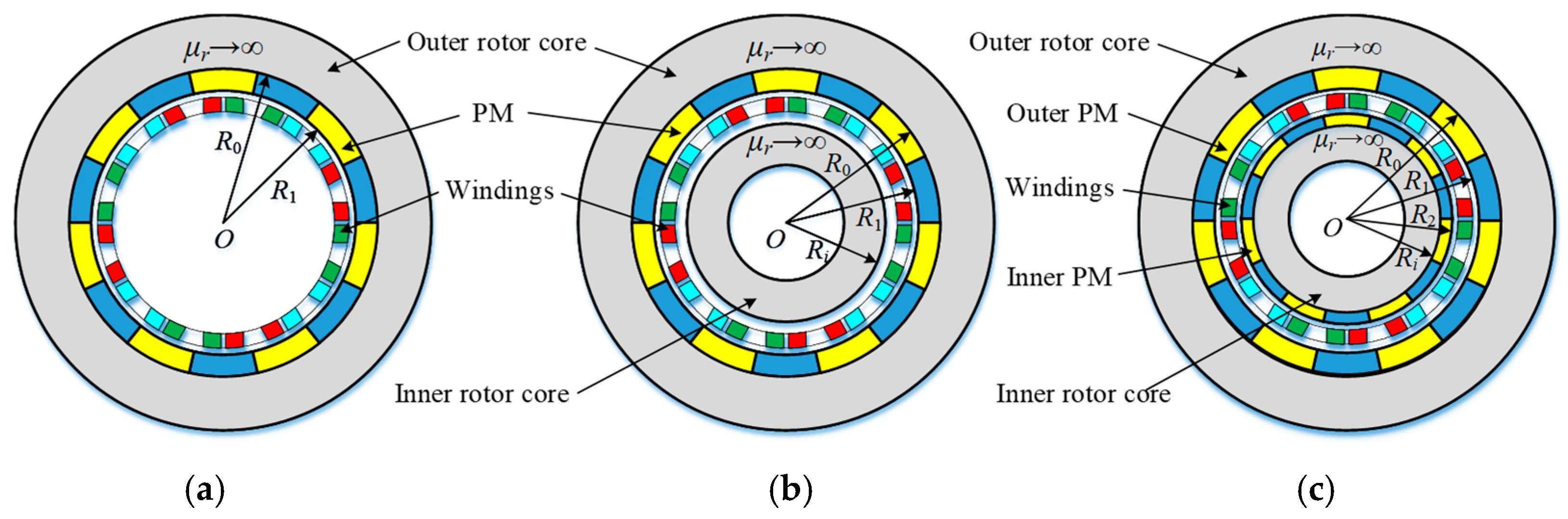
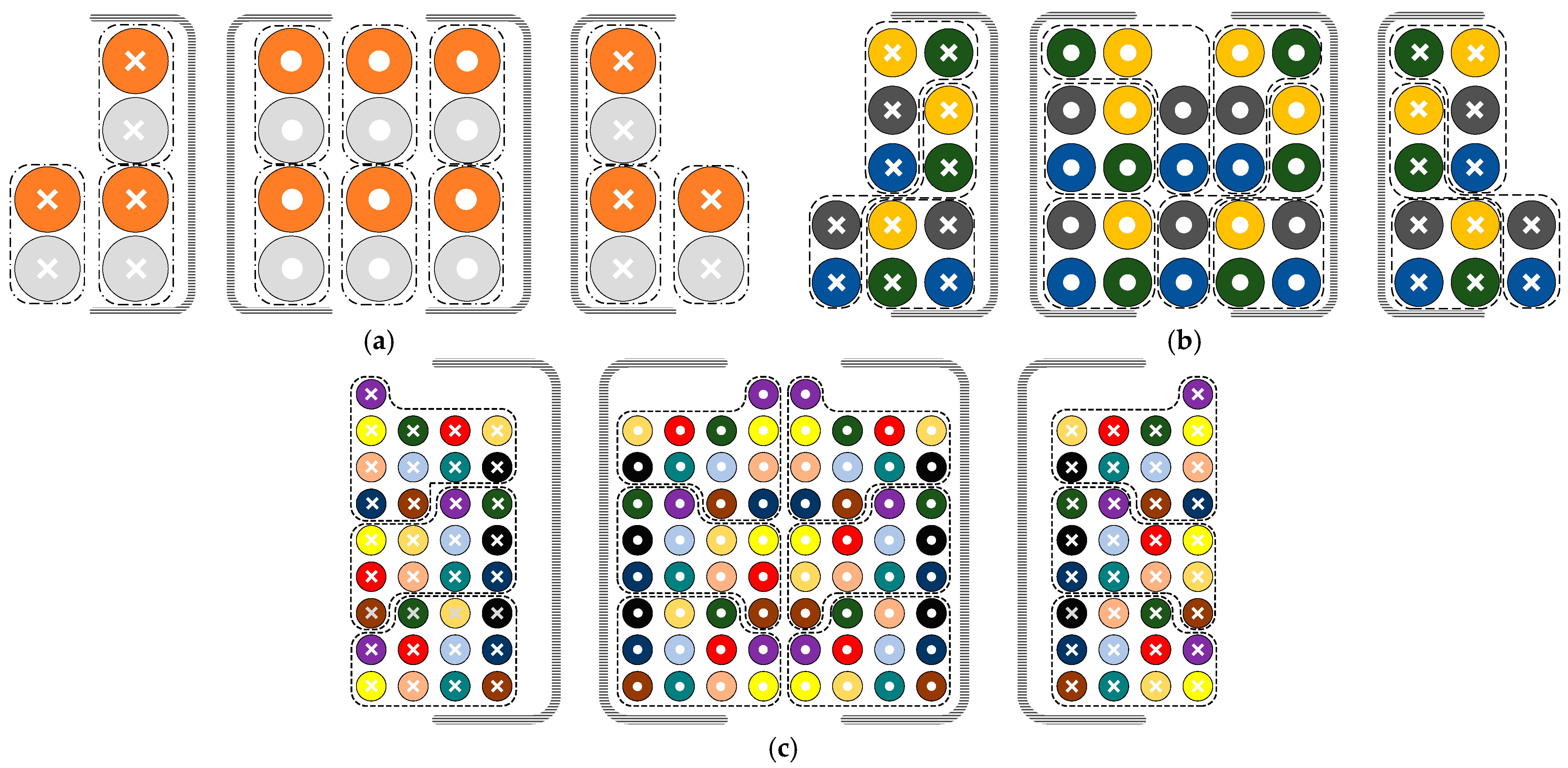
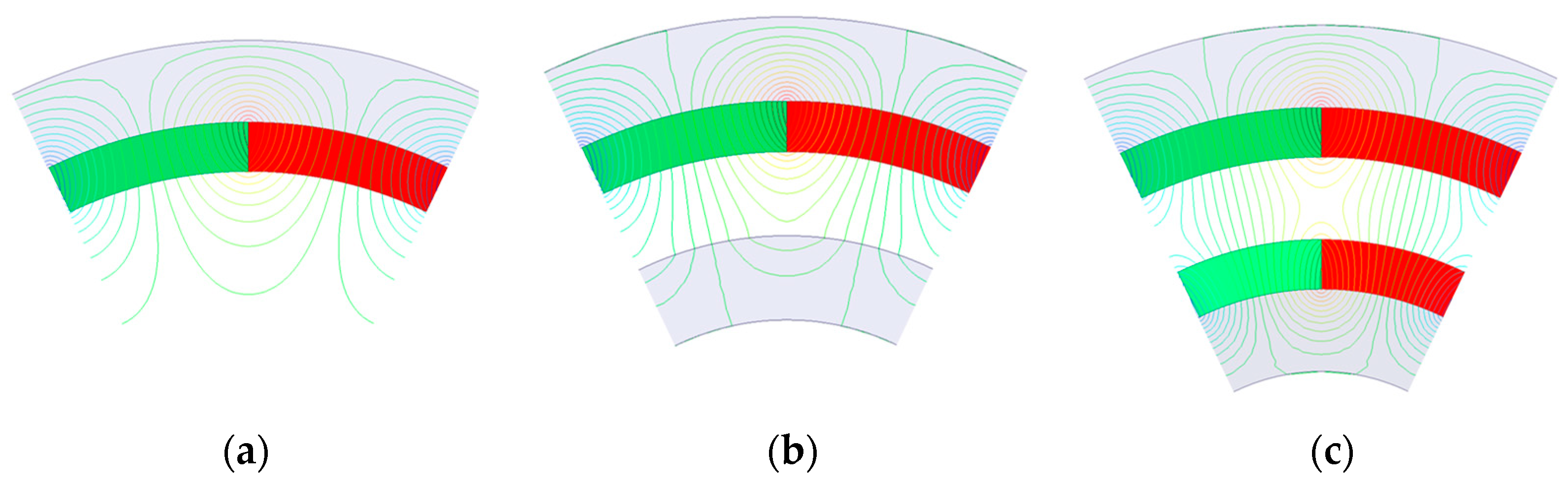
2.1. Structures and Structural Parameters of Iron Coreless PMBLDC Motors

As shown in Figure 1, three types of stator iron coreless PMBLDC motors with similar structures are studied. The Type I motor has only the outer rotor core with PMs mounted on the inner surface and the stator windings. On the basis of the structure of the Type I motor, the Type II motor has an additional inner rotor core, which rotates together with the outer rotor core and PMs. The Type III motor possesses dual rotors with surface mounted PMs. Table 1 tabulates the structural parameters of these three motors. To miniaturize the design, all three motors use full teeth concentrated windings, which have smaller end windings than the commonly used distributed windings.

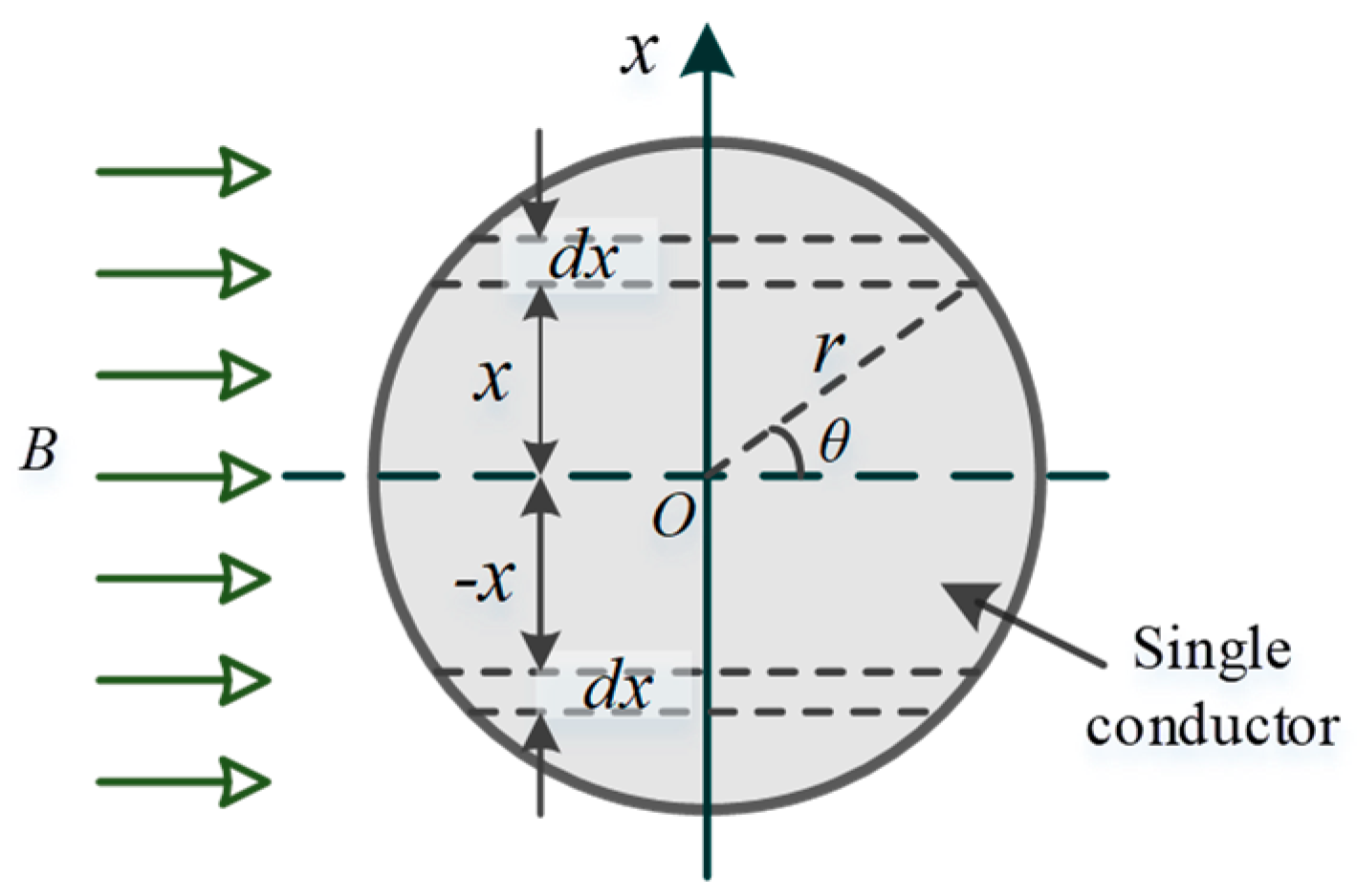
2.2. Analytical Model of Eddy Current Loss in a Round Wire

For the stator iron coreless PMBLDC motors, the windings are exposed directly to the high-intensity rotating magnetic field [27], and heavy eddy currents are induced in the conductor strands, resulting in eddy current loss. The winding eddy current loss can be obtained by summing up the eddy current loss of all conductor strands.
Figure 2 illustrates the cross section of a single round conductor exposed to a magnetic field of flux density B in the horizontal direction and alternating with time at a frequency f. The eddy current loss in a microelement dx in the conductor dw1 can be expressed as [28]:
d w 1 = u 2 R = 4 π f B x 2 σ a cos θ d x = 16 π 2 f 2 B 2 x 2 σ a cos θ d x
The geometrical relationships between dx, r, and θ can be obtained as:
x = r sin θ d x = r cos θ d θ
By substituting Equation (2) into Equation (1) and integrating on both sides, one can obtain the eddy current loss of the single round conductor as:
w 1 = 16 π 2 f 2 B 2 σ r 4 l 0 π / 2 sin 2 θ cos 2 θ d θ = π 3 f 2 r 4 B 2 σ l = 1 16 S D 2 B 2 ω 2 σ l
where r, D, l, and S are the radius, diameter, axial length, and cross-sectional area of the conductor, respectively, σ = 5.8 × 10⁷ S/m is the conductivity of the copper conductor, and ω =f is the angular frequency.
By neglecting the axial end effect of the motor and assuming the conductors are distributed evenly in each layer, one can obtain the total eddy current loss of stator winding, wwe, by summing up the eddy current loss of all conductor strands as:
w w e = M 128 N π D 4 σ l ω 1 2 j = 1 N k = 1 2 k + 1 2 B r m j ( 2 k + 1 ) 2 + B t m j ( 2 k + 1 ) 2
where N is the number of layers and M the number of conductor strands of the stator winding.
Let
K j = k = 1 2 k + 1 2 B r m j ( 2 k + 1 ) 2 + B t m j ( 2 k + 1 ) 2
and we have:
w w e = M 128 N π D 4 σ l ω 1 2 j = 1 N K j
where ω1 is the angular frequency of the fundamental harmonic, and Brmj(2k+1) and Btmj(2k+1) are the magnitudes of radial and tangential components of the (2k + 1)-th harmonic of flux density at the j-th winding layer, respectively.

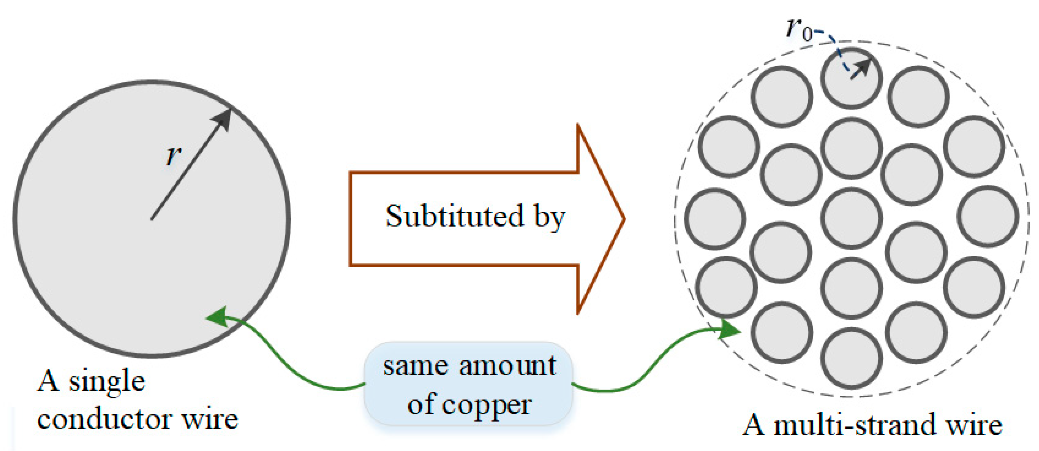
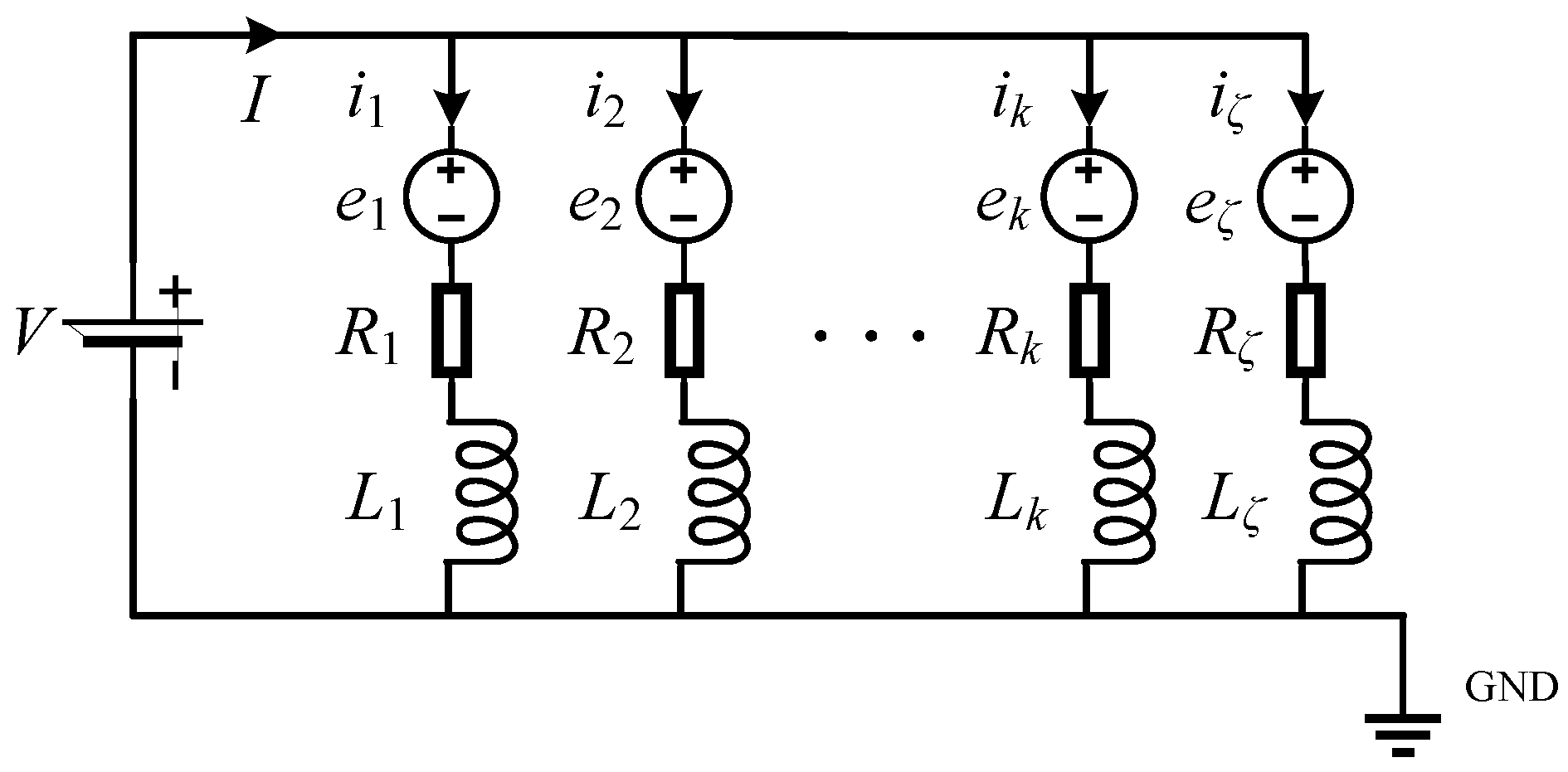
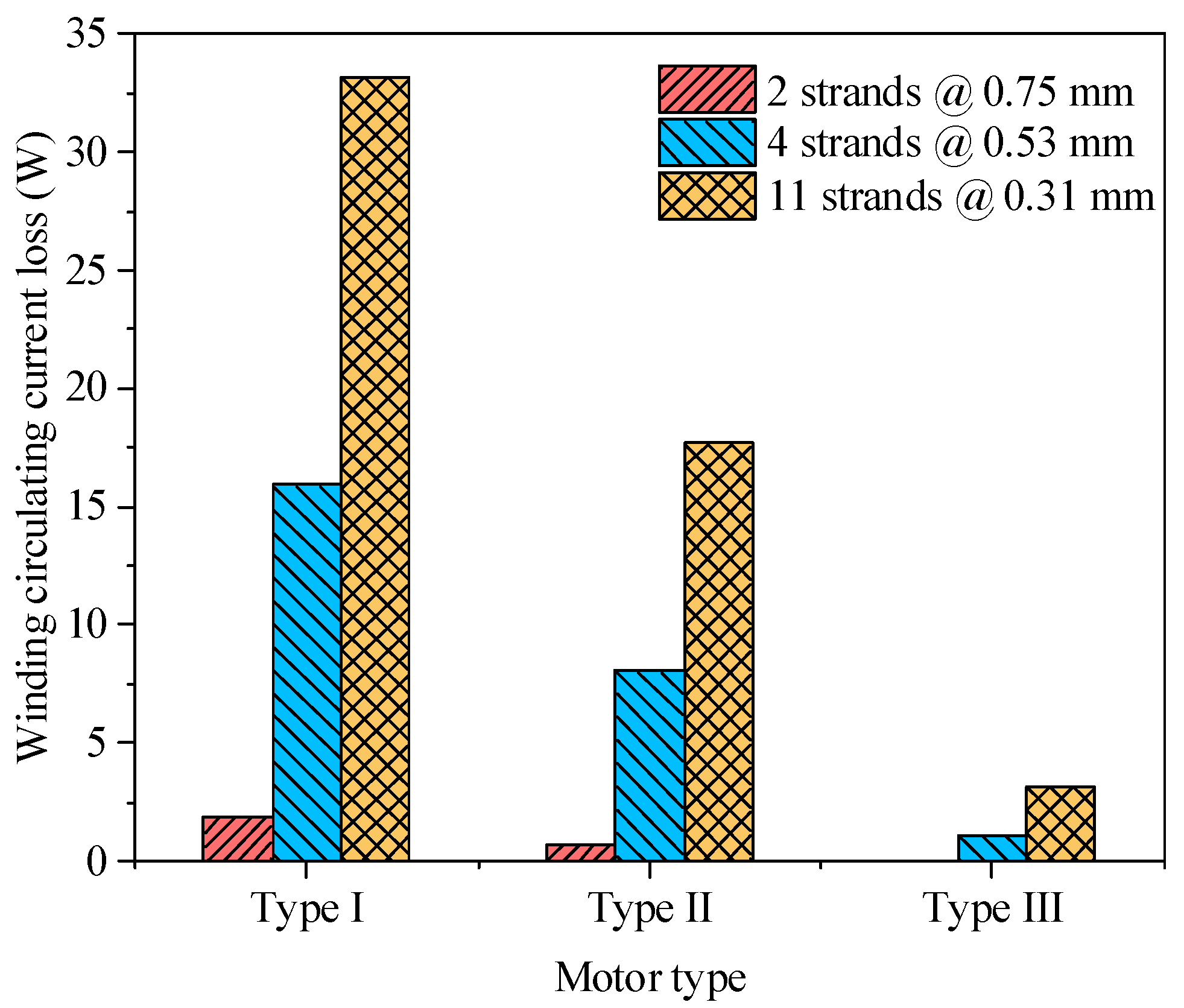
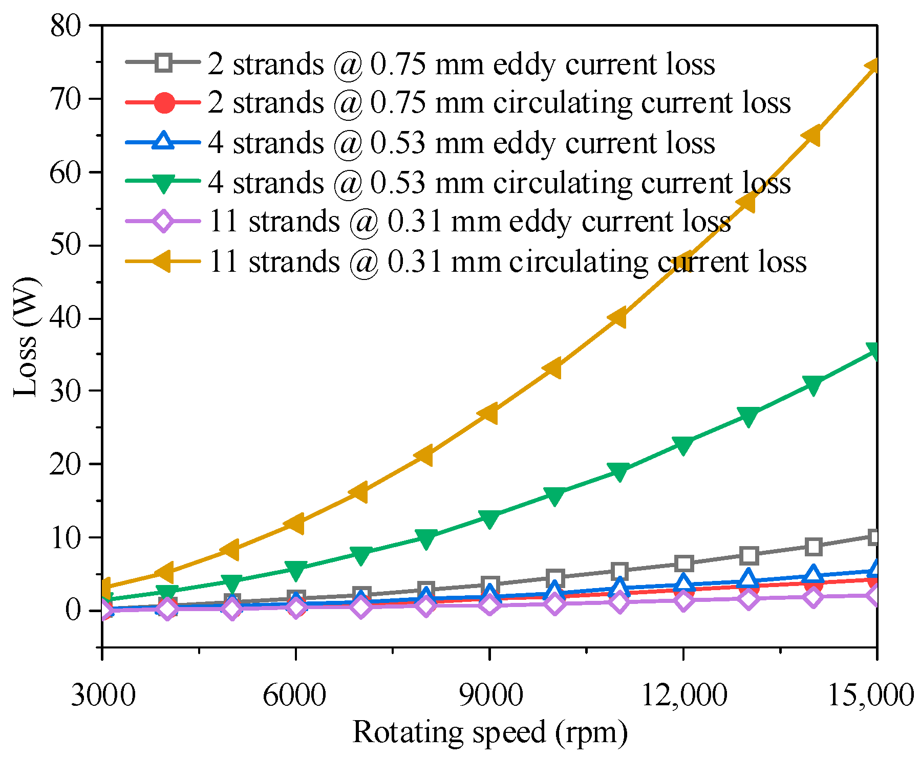
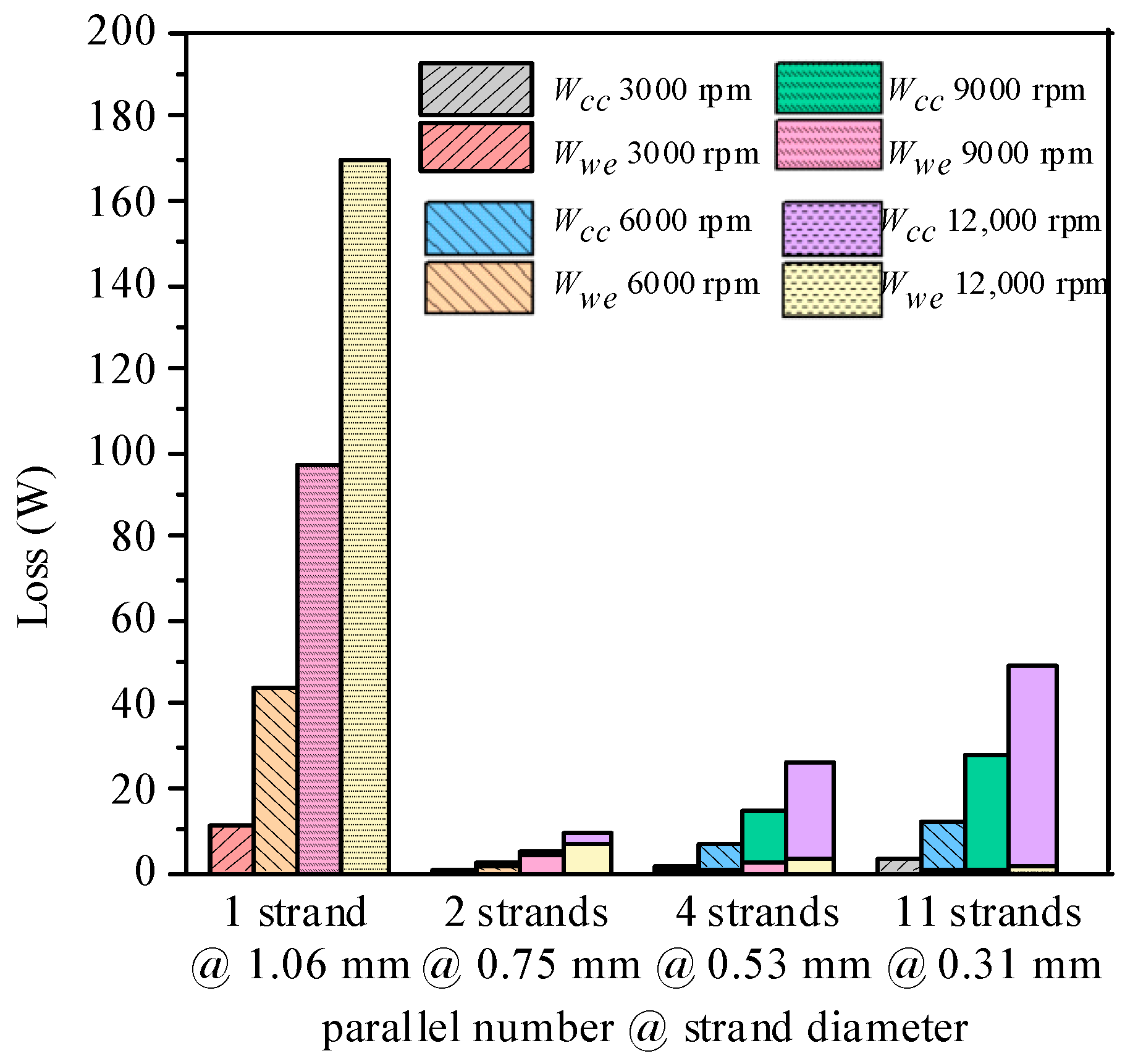
2.3. Circulating Current Loss of Multiple Parallel Strands

While using multiple parallel conductor strands with a cross-sectional area equivalent to that of a single conductor, as illustrated in Figure 3, can effectively reduce the winding eddy current loss, the induced electromotive forces (EMFs) in these parallel conductor strands are different from each other due to the difference in the magnetic field distribution in the winding region, and time varying circulating currents are generated among the multiple parallel conductor strands, resulting in circulating current loss.
Assume the stator phase winding is wound by a wire of ζ parallel conductor strands. The strand radius r0 can found by r02 = r2/ζ, where r is the radius of single solid conductor.
Figure 4 shows an equivalent circuit of the multiple parallel conductor strands in a phase winding. The parameters e, R, and L are the commonly used acronyms and abbreviations of electromagnetic motive force, electrical resistance, and inductance of the parallel strands. The strand circulating currents deduced from Kirchhoff’s law in the phase winding can be calculated by:
k = 1 ζ i c k = k = 1 ζ V e k R k 2 + L k 2 = 0
where ick, ek, Rk, and Lk (k = 1, 2, 3, …, ζ) are the current, induced EMF, resistance, and self-inductance of the k-th parallel strand, respectively, and V the phase is the terminal voltage.
The circulating current loss of the whole phase winding deduced from Ohm’s law, wcc, can be obtained as:
w c c = k = 1 ζ m · a · i c k 2 R k
where a is the number of parallel branches of each phase winding, and m the number of phases.
The parameters, a, ζ, and M can be related by:
M = 2 a m κ ζ
where κ is the phase winding number of turns.

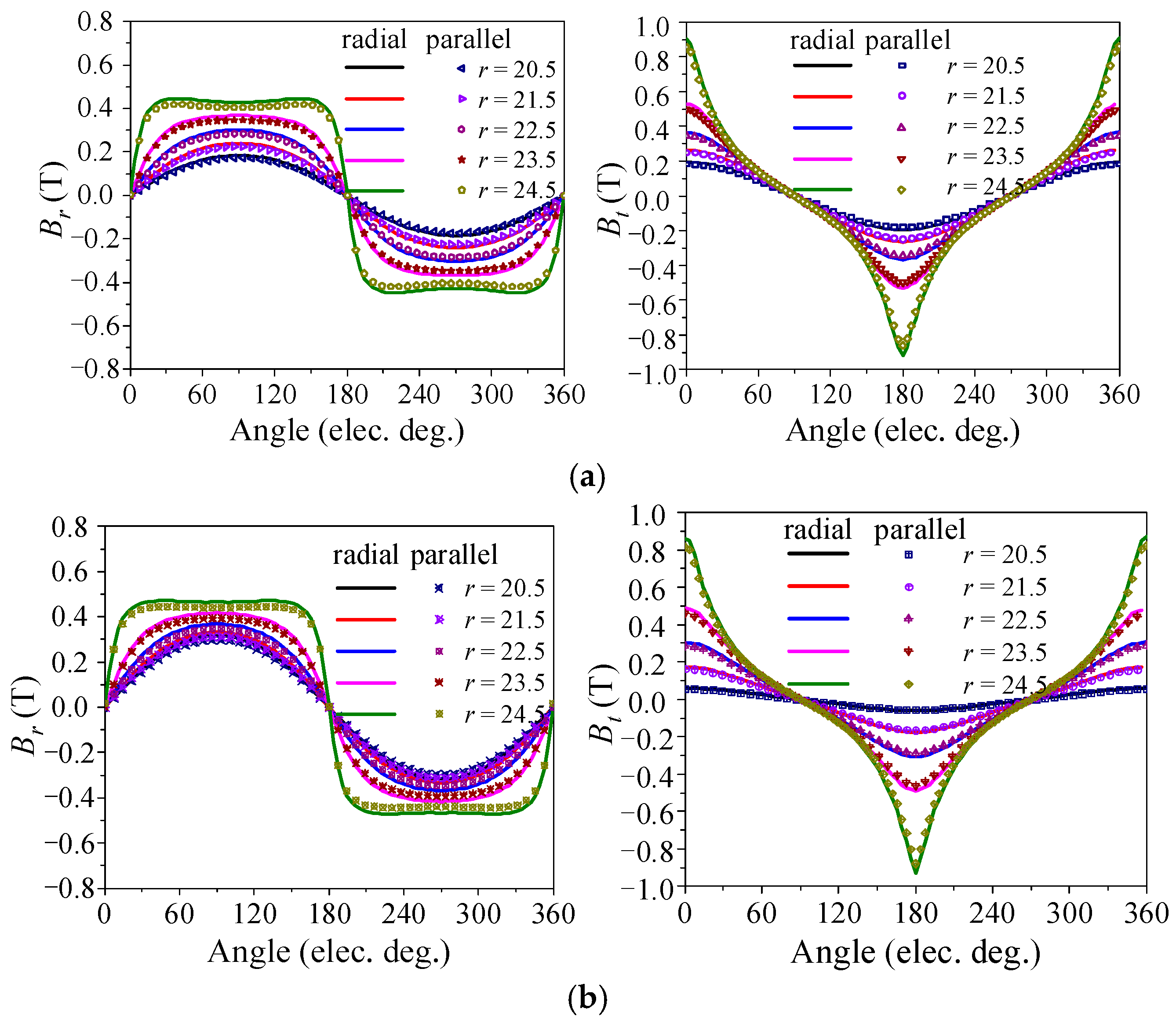
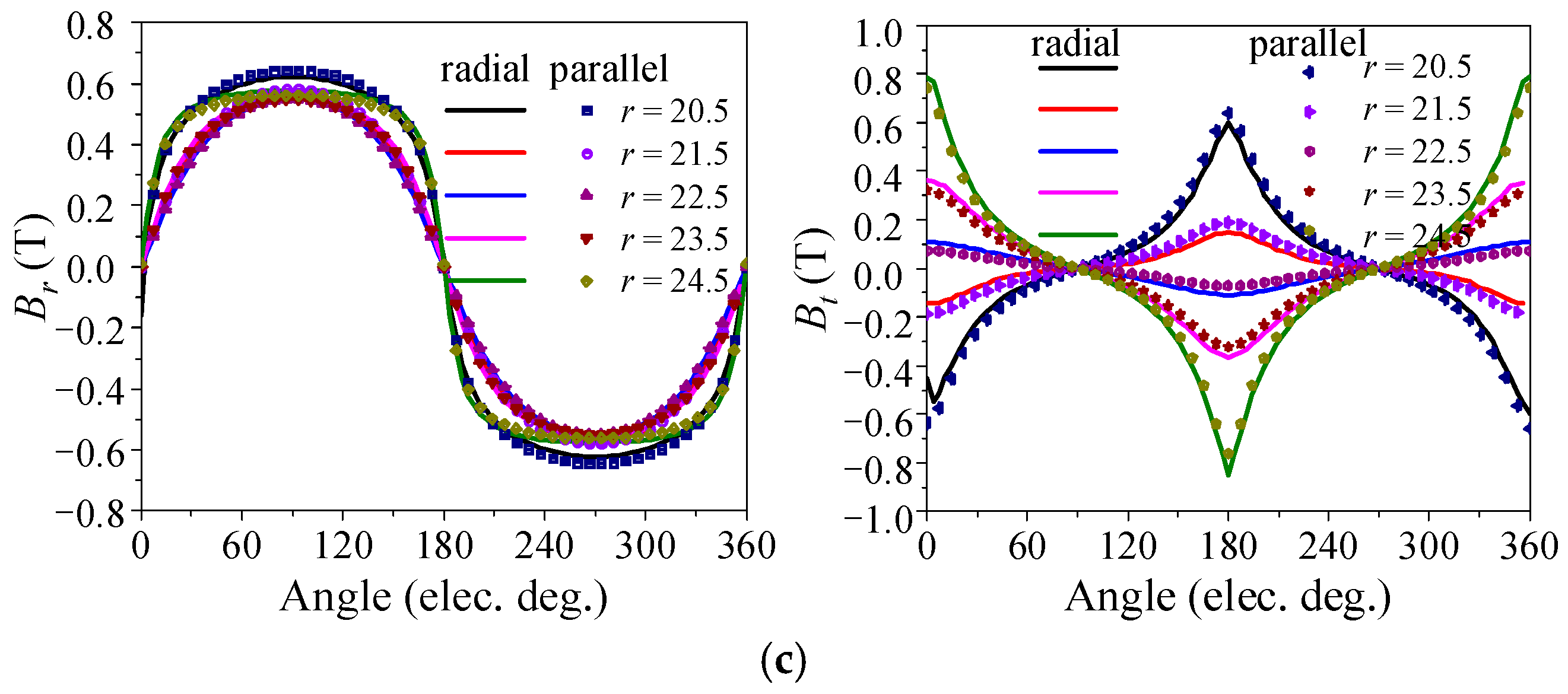
3. Eddy and Circulating Current Losses

To improve the power density of the motor, the motor power losses must be minimized. The power losses of the stator iron coreless PMBLDC motor include the rotor iron core loss, the eddy current loss in PMs, and the winding copper loss. Due to the PMs mounted on the rotor cores rotating synchronously with each other, there are no relative movements of the alternating magnetic field between the rotor components. The loss of the rotor iron core and eddy current loss in PMs are so small that they can be neglected. Among them, the major component is the winding copper loss, which is generated by the stator phase current, and eddy and circulating currents in the multiple parallel thin conductor strands. For the wire gauges used in this paper, the ratio of the resistance between AC to DC for different cases is close to 1. Hence, the proximity and skin effects are neglected in the copper loss calculation here. In the constant torque mode, the phase current is fixed for a given load torque, and thus, the winding copper loss can be minimized by properly balancing the effects of the eddy and circulating currents.
As shown in Figure 3, since the cross-sectional areas of the single conductor and the multiple thin conductor strands of the stator winding are the same, their DC resistances are same, whereas the AC resistances are very different. As discussed previously, while the eddy current loss can be suppressed by using multiple parallel thin conductor strands, the circulating current loss of the whole phase windings will increase.
The objective of the winding design presented below is to find the optimal diameter of thin conductor strands that can yield the minimum winding copper loss through a proper trade-off between the eddy and circulating current losses. The previous analysis shows that various factors, such as the strand diameter, magnetization of PMs, and rotating speed, can influence the eddy and circulating current losses simultaneously. To achieve the above objective, these factors are investigated as follows.

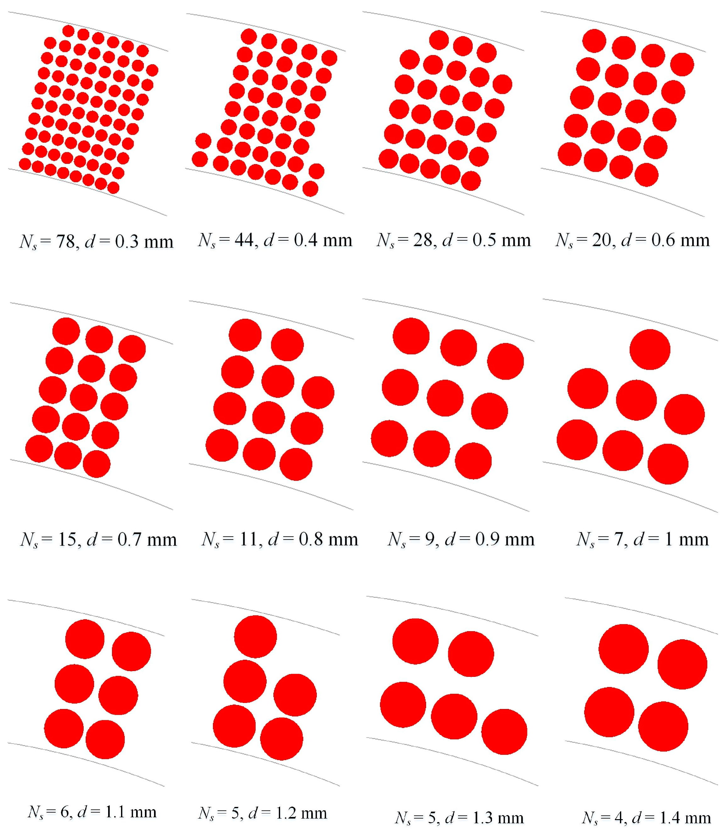
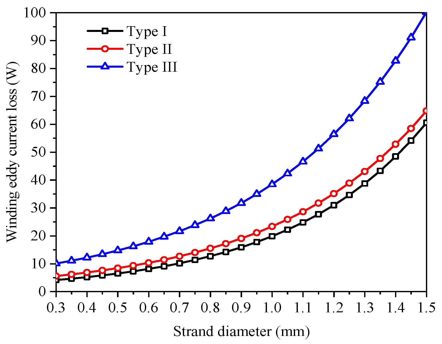
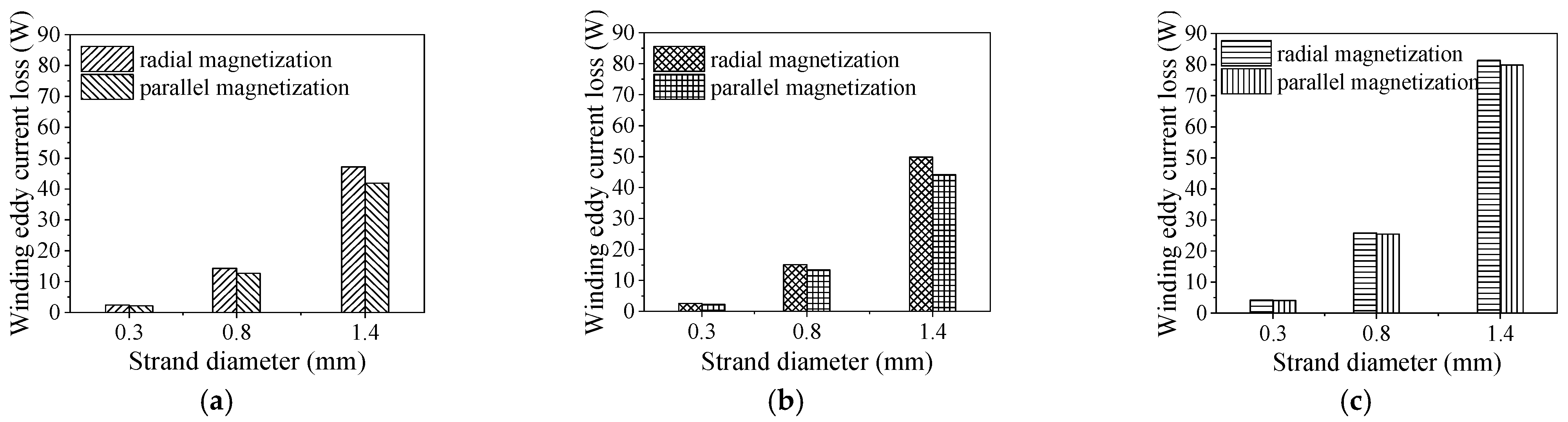
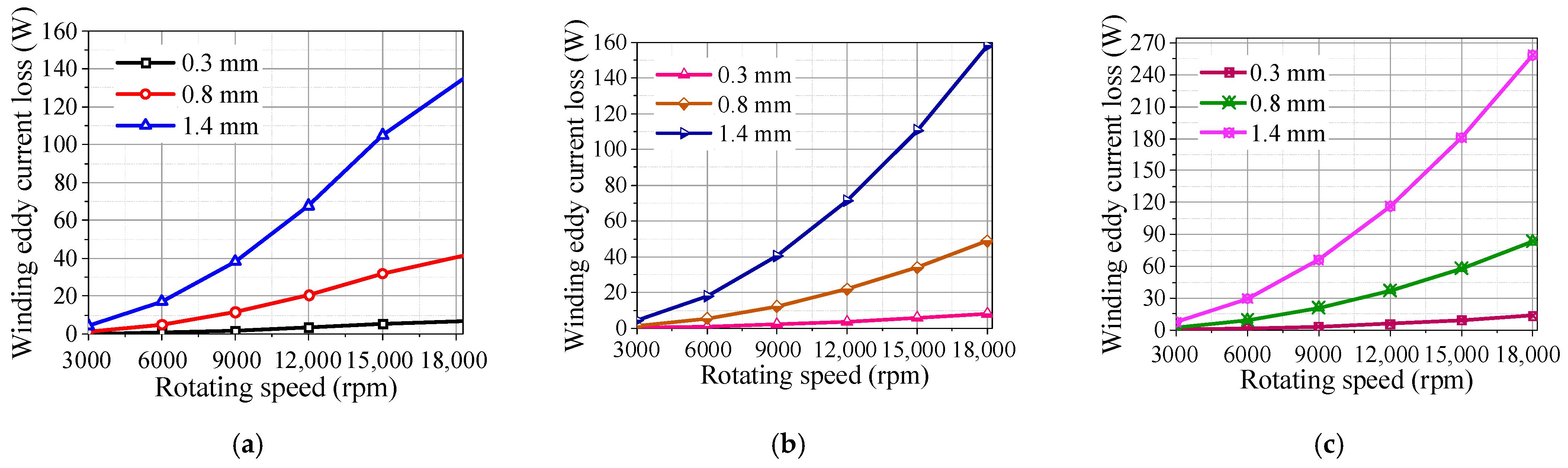
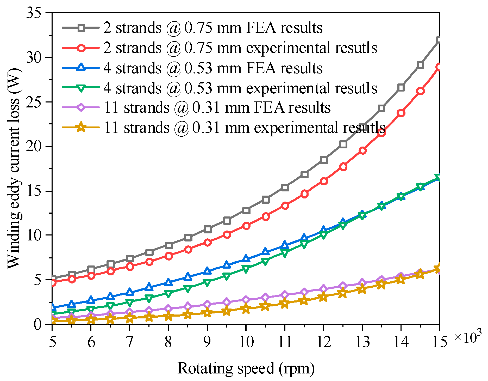
3.1. Effects of Strand Diameter

As analyzed previously, the eddy current loss of parallel conductor strands of stator winding is directly proportional to the fourth power of the strand diameter. Because the number of parallel conductor strands is related to the strand diameter, it can be deduced that the circulating current loss is inversely proportional to the square of the strand diameter.
Under the condition of using the same amount of copper, the diameter of parallel thin conductor strands can be calculated by:
d = D 2 a × κ × m Q N s
where Q is the slot number, and Ns the number of parallel thin conductor strands in each slot.
The eddy current losses for different pairs of the number and diameter of the parallel thin conductor strands in each slot, as shown in Figure 5, are calculated by the two dimensional (2D) finite element analysis (FEA) under the condition of using the same mesh size. Figure 6 depicts the FEA results of the winding eddy current losses of Type I, II, and III stator iron coreless PMBLDC motors versus the strand diameter at a rotating speed of 10,000 rpm. As shown, the winding eddy current losses of these different stator iron coreless PMBLDC motors increase nonlinearly versus the strand diameter. The winding eddy current loss of the Type III motor is higher than that of the other two types of motors, due to the extra airgap flux density produced by the inner PMs on the rotor core. The difference between the winding eddy current losses of the Type III motor and the other two types of motors increases with the strand diameter, whereas the winding eddy current losses of Type I and II motors vary along the same trend versus the strand diameter with a small difference.
The circulating current loss of stator phase winding versus the number of parallel strands is calculated for the parallel thin conductor strands connected in the type of concentrated winding, as illustrated schematically in Figure 7, where the signs of dots and crosses indicate the directions of strand currents flowing out and in, perpendicular to the paper surface, respectively. The same thin strands in different turns are colored the same, and the strands of the same wire are enclosed with dashed lines. Under the assumption that the same amount of copper is filled in one slot, one can choose different pairs of number and diameter of parallel strands. Three combinations of number and diameter of parallel thin strands, i.e., 2 strands @ 0.75 mm, 4 strands @ 0.53 mm, and 11 strands @ 0.31 mm, are selected for the 2D FEA of circulating current loss.
The circulating current losses of Type I, II, and III stator iron coreless PMBLDC motors are obtained by the 2D FEA of transient magnetic fields and (7) at 10,000 rpm. Figure 8 plots the circulating current losses of Type I, II, and III motors for the above combinations of the number and diameter of strands in a phase winding. As shown, for each motor type, the circulating current loss increases as the number of strands increases. Among the three motor types, for a given pair of strand number and diameter, the Type I has the highest circulating current loss and the Type III motor has the least circulating current loss.

3.2. Effects of Magnetization

In surface mounted PMBLDC motors, the PMs of different types of magnetizations can be adopted, such as the radial, parallel, sinusoidal, and Halbach array magnetizations, etc. Figure 9 shows the magnetic field distribution in the air gap under one pole pair with parallel magnetization of the three-stator iron coreless PMBLDC motor types. It can be found that the polarity for Type III is bipolar, and the other two types are unipolar.
Figure 10 shows the 2D FEA results of the radial and tangential components of the airgap flux density in Type I, II, and III motors with PMs magnetized in the radial and parallel directions. The symbol r here means the different calculation radii of the airgap, and it ranges from 20.5 mm to 24.5 mm, with a step of 1 mm. The difference is very little between the results produced by different magnetized PMs. The tangential components difference of airgap flux density for Type III in comparison to the other two types in Figure 10 resulted from the rotor structure difference. Due to harmonic differences, the radial and tangential components of magnetic flux density appeared to be flat-topped and shaped waves.
For the convenience of simulation and to clearly display the results, three windings of different strand diameters of 0.3 mm, 0.8 mm, and 1.4 mm are chosen. Figure 11 shows the 2D FEA results of the winding eddy current loss of Type I, II, and III motors with PMs magnetized in the radial and parallel directions versus the strand diameter at 10,000 rpm. As shown, for a given strand diameter, the Type III motor has the highest winding eddy current loss, and the Type I motor the lowest. For a given strand diameter, the difference between the winding eddy current losses of Type III motors with PMs magnetized in different directions is the smallest. For a given motor type with a given strand diameter, the winding eddy current loss of motor with PMs magnetized in parallel is smaller than that of the motor with radially magnetized PMs. Hence, the PMs magnetized in parallel is preferred for the stator iron coreless PMBLDC motors to reduce the winding eddy current loss.

3.3. Effects of Rotating Speed

It can be deduced from the analytical analysis that both the winding eddy and circulating current losses are proportional to the quadratic of the rotating speed.
Figure 12 illustrates the winding eddy current losses of Type I, II, and III motors with a different strand diameter versus the rotating speed. As shown, the winding eddy current loss can be kept small within the calculated speed range with a small strand diameter. The winding eddy current losses of all motor types increase nonlinearly with the rotating speed. For a given strand diameter, the winding eddy current loss of the Type III motor is the highest, and that of the Type I motor is the smallest, because of the rotor structural difference.
As can be seen from Figure 10, the radial magnetic field amplitude variation ranges of Types I–III are 0.18 T~0.42 T, 0.32~0.44, and 0.56 T~0.62 T, respectively. It can be easily found that the amplitude difference of the magnetic flux density of Type I is more distinct than the other two motor types. Hence, the problem regarding circulating current loss will be more serious. In order to investigate the winding eddy and circulating current losses comprehensively and show circulating current losses obviously, taking the Type I motor as an example, the 2D FEA results of the winding eddy and circulating current losses versus the rotating speed in three different cases, i.e., 2 strands @ 0.75 mm, 4 strands @ 0.53 mm, and 11 strands @ 0.31 mm, are shown in Figure 13. The winding eddy and circulating current losses of the Type II and III motors can be carried out in the same way. From the results, one can readily observe: (1) the winding eddy and circulating current losses of the three cases increase nonlinearly with the rotating speed; (2) in the case of two strands @ 0.75 mm, the winding circulating current loss is lower than the winding eddy current loss, whereas in the case of four strands @ 0.53 mm, the winding circulating current loss becomes significantly higher than the winding eddy current loss.
To compare with the winding loss of a single conductor winding, a case of one strand @ 1.06 mm is also calculated. In this case, only the eddy current loss exists in the stator winding. The winding eddy and circulating current losses of the four different cases in several typical speeds are plotted in Figure 14. It is clear that the circulating current loss increases rapidly while the winding eddy current loss decreases sharply as the number of strands increases. Thus, the sum of the winding eddy and circulating current losses decreases at first and then increases. Based on the investigation in this paper, the sum of the winding eddy and circulating current losses in the case of two strands @ 0.75 mm is the smallest, which validates that the eddy and circulating current losses should be investigated comprehensively to obtain minimum winding losses. The optimum parallel strand number and the corresponding diameter in one turn winding of the other two motor types can be achieved in the same way.

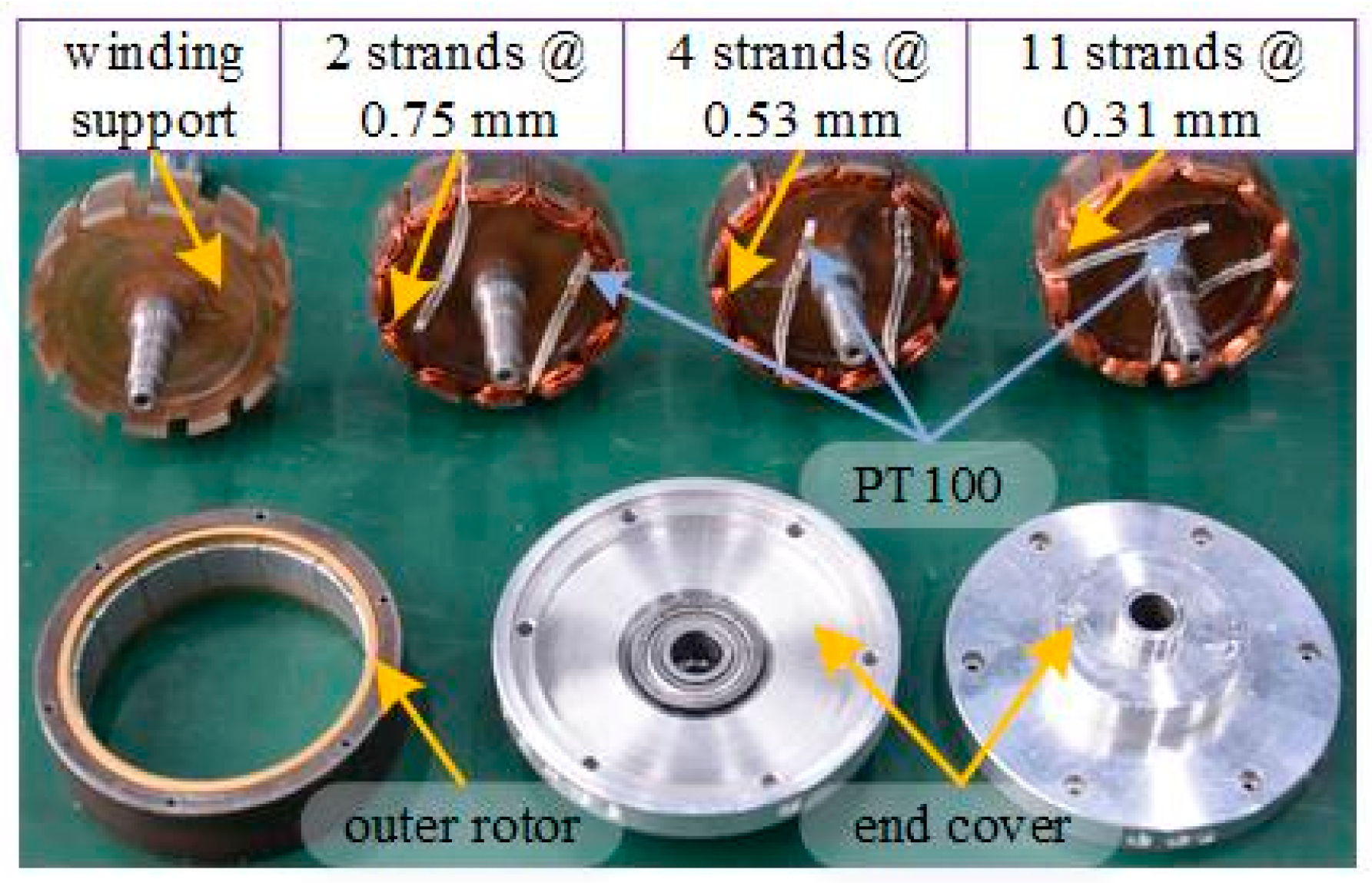
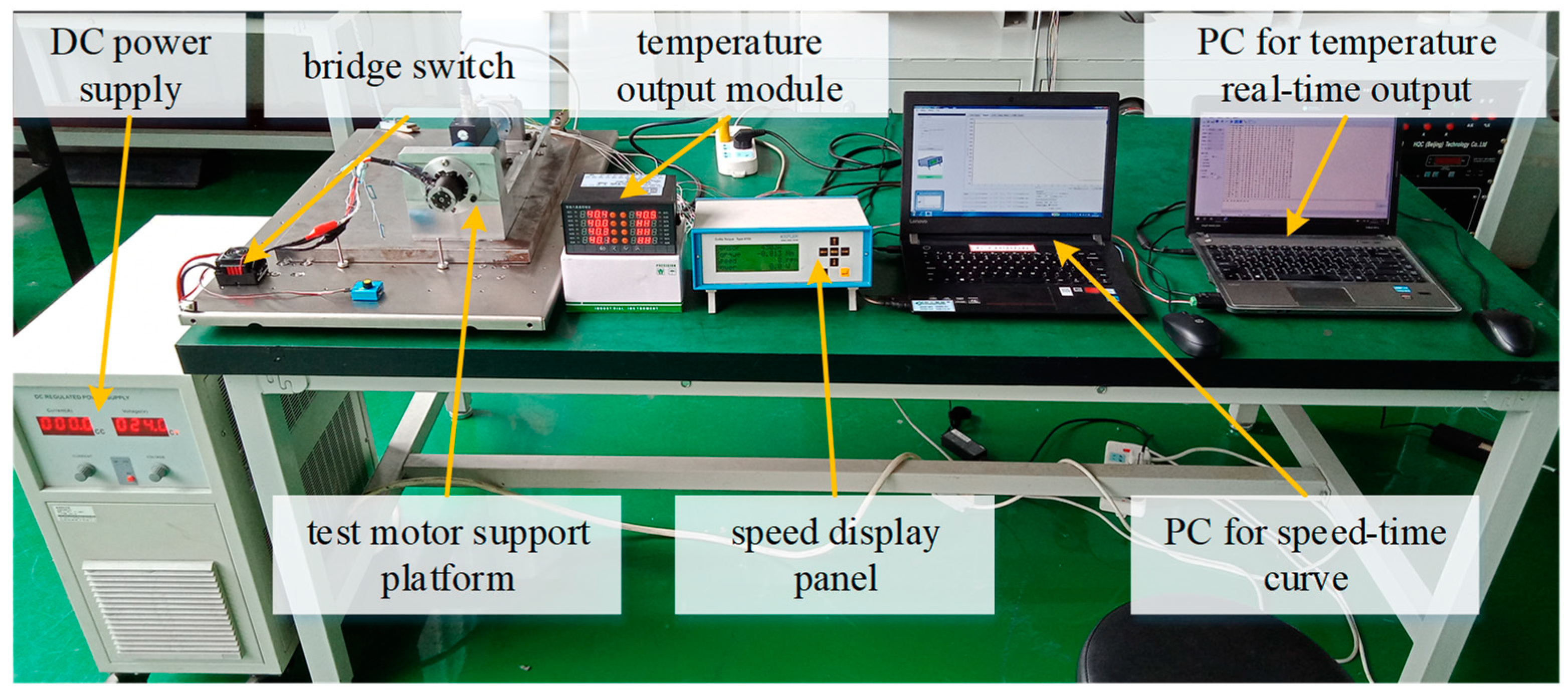
4. Experimental Testing

4.1. Experiment for Measuring Winding Eddy Current Loss

Three prototypes of Type I stator iron coreless PMBLDC motors with 2 strands @ 0.75 mm, 4 strands @ 0.53 mm, and 11 strands @ 0.31 mm, respectively, were fabricated and tested experimentally to verify the theoretical analyses. Figure 15 shows a photo of the prototype stator and rotor components of the Type I motors with three combinations of the number and diameter of conductor strands. Each phase winding has three turns. The rotor PMs are with a parallel magnetization for the three prototypes of the Type I motor, and the cases with PM radial magnetization can be carried out by the same way.
Figure 16 shows the winding eddy current loss test system. The test motor is driven by a high-speed BLDC motor with the rated speed of 30,000 rpm. The winding eddy current loss of the motor can be measured for the three cases by the free stopping and loss separation methods. Assuming J (kg·m2) is the inertia of rotating parts of the driving motor, torque sensor, coupling, and the test motor, the angular acceleration versus time can be obtained by the derivation of the free speed dropping curve, which is collected from torque sensor through rs-485 can. The loss of the test motor system, w, can be calculated by Equation (10), as shown below. The total loss is the integral of w in the whole free stopping time. One can express the winding eddy current loss, wwe, as the difference between the losses of the stator support with and without phase windings.
T = J · β w = T · ω
where T is the torque in Nm produced by the loss, β the angular acceleration in rad/s2, and ω the angular velocity in rad/s.
Figure 17 plots the 2D FEA and experimental results of the winding eddy current loss of the Type I motor for the three different cases. The error between the experiment and simulations is approximately 12% and 15% for the Type I and II motors, respectively, and for the Type III motor, the error is approximately 31%. It can be seen that the winding eddy current loss is higher in the motor with thick strands than that in the motor with thin strands, which agrees with the previous analysis. The experimental results have also shown good agreement with the FEA results. The small difference between the FEA and experimental results in the case of two strands @ 0.75 mm can be attributed mainly to the difference in the bearing pre-tightening before and after the change of stators.

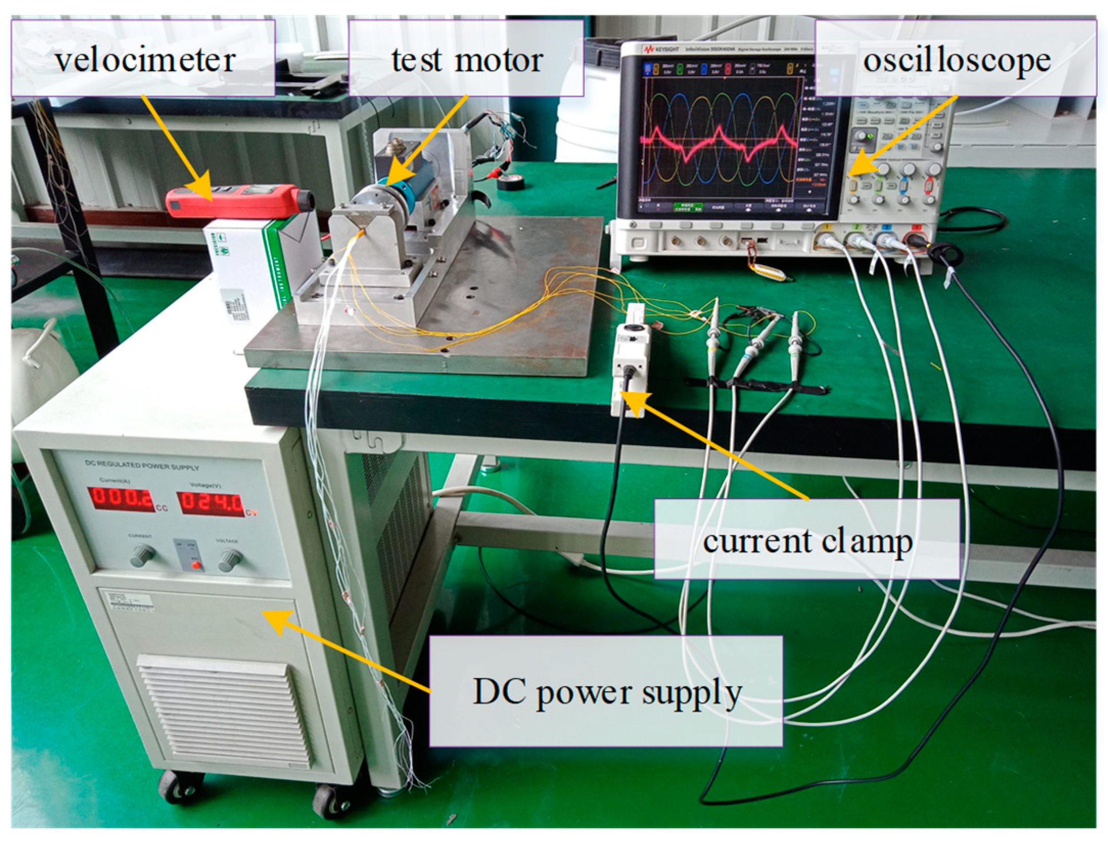
4.2. Measurement of Circulating Strand Currents

Figure 18 shows a photo of the experimental testing system for measuring the strand currents in the stator phase winding by using current clamps. Two cases of Type I motors with different strand numbers and diameters, i.e., two strands @ 0.75 mm and four strands @ 0.53 mm, were tested. In the case of two strands @ 0.75 mm, the two ends of the two parallel strands on the same side were connected to one probe, and then the two dangling ends were connected to the other two probes of the oscilloscope, respectively.
It can be found from the induced EMFs shown on the oscilloscope that the magnitudes and phase angles of EMFs in the parallel strands are different with each other at a certain rotating speed. The waveform of the circulating strand current generated by the different strand EMFs was measured by the current clamp and displayed on the oscilloscope. The rotating speed of the test motor was measured by a velocimeter. As for the other case of four strands @ 0.53 mm, where A1–A4 are the labels for the four individual strands, the combinations of A1–A4 and A2–A3 are chosen to be tested, respectively, by the same testing method for the case of two strands @ 0.75 mm. Table 2 tabulates the experimental results of the two cases operated in the speed range from 3000 rpm to 15,000 rpm, with a step of 3000 rpm.
Because of the experimental error, some measured strand currents with lower speed were a little bigger than those with higher speed. However, the overall trend of the measured strand currents along with the rotating speed is theoretically right. As the rotating speed increases, the strand currents in the case of two strands @ 0.75 mm increase significantly. In the case of four strands @ 0.53 mm, the circulating strand currents are much smaller, and increase at a much smaller rate than the case of two strands. In principle, the circulating strand currents in the selected two parallel strands in the case of four strands should be somewhat higher than those in the case of two strands if the strands are untwisted because of the reduction of resistance. However, due to some uncontrollable factors in the manual winding process, the strands in the case of four strands @ 0.53 mm were twisted. By comparing with the calculated currents in the untwisted two parallel strands, the effects of twisting strands can be revealed.

5. Conclusions

In this paper, a comprehensive study has been conducted to calculate the winding eddy and circulating current losses of multiple parallel thin strands for stator iron coreless PMBLDC motors, which can be beneficial for the purpose of improving the power density. The results show that the winding eddy current loss of the Type III motor is much higher than the other two types and is more sensitive to the strand diameter. The calculation results of the circulating current loss with the multiple parallel thin strands obtained by the 2D FEA shows that the circulating current loss of the Type I motor for a given pair of the number and diameter of strands is higher than those of the other two motor types. The winding eddy and circulating current losses for different winding cases are analyzed comparatively, and the optimal winding case with the smallest winding losses is selected through a compromise between the eddy current loss and circulating current loss. Finally, three prototypes of the Type I stator iron coreless PMBLDC motors with different combinations of the number and diameter of conductor strands were manufactured and tested for measuring the winding eddy losses and circulating currents. The experimental results agree well with the theoretical results. The method proposed in this paper provides a guideline for further improving the power density of stator iron coreless PMBLDC motor types. In addition, rectangular strand wires will be assessed in future studies.

Author Contributions

L.Y., J.Z. (Jing Zhao) and W.F. were in charge of the whole trial, data analysis, and wrote the manuscript; X.L. and J.Z. (Jianguo Zhu) assisted with the manuscript checking, and C.A. reviewed and edited the manuscript. All authors have read and agreed to the published version of the manuscript.

Funding

Supported in part by the National Natural Science Foundation of China (No. 51977011), and Open Foundation of the State Key Laboratory of Fluid Power and Mechatronic Systems (No. GZKF-202124).

Data Availability Statement

Not applicable.

Conflicts of Interest

The authors declare no conflict of interest.

References

  1. Zhou, X.X.; Chen, X.; Zeng, F.Q.; Tang, J.Q. Fast commutation instant shift correction method for sensorless coreless BLDC motor based on terminal voltage information. IEEE Trans. Power Electron. 2017, 32, 9460–9472. [Google Scholar] [CrossRef]
  2. Bolam, R.C.; Vagapov, Y.; Anuchin, A. Performance comparison between copper and aluminium windings in a rim driven fan for a small unmanned aircraft application. In Proceedings of the 2020 XI International Conference on Electrical Power Drive Systems (ICEPDS), St. Petersburg, Russia, 4–7 October 2020. [Google Scholar]
  3. Zhang, Z.M.; Deng, Z.Q.; Gu, C.; Sun, Q.G.; Peng, C.; Pang, G.C. Reduction of rotor harmonic eddy-current loss of high-speed PM BLDC motors by using a split-phase winding method. IEEE Trans. Energy Convers. 2019, 34, 1593–1602. [Google Scholar] [CrossRef]
  4. Liu, Y.; Zhang, Z.; Wang, C.; Geng, W.; Yang, T. Design and analysis of oil-immersed cooling stator with nonoverlapping concentrated winding for high-power ironless stator axial-flux permanent magnet machines. IEEE Trans. Ind. Electron. 2021, 68, 2876–2886. [Google Scholar] [CrossRef]
  5. Damiano, A.; Floris, A.; Fois, G.; Marongiu, I.; Porru, M.; Serpi, A. Design of a high-speed ferrite-based brushless DC machine for electric vehicles. IEEE Trans. Ind. Electron. 2017, 53, 4279–4287. [Google Scholar] [CrossRef] [Green Version]
  6. Burnand, G.; Thabuis, A.; Araujo, D.M.; Perriard, Y. Novel optimized shape and topology for slotless windings in BLDC machines. IEEE Trans. Ind. Appl. 2020, 56, 1275–1283. [Google Scholar] [CrossRef]
  7. Praveen, R.P.; Ravichandran, M.H.; Achari, V.T.S.; Raj, V.P.J.; Madhu, G.; Bindu, G.R. A novel slotless Halbach-array permanent-magnet brushless DC motor for spacecraft applications. IEEE Trans. Ind. Electron. 2012, 59, 3553–3560. [Google Scholar] [CrossRef]
  8. Huang, Y.K.; Ge, B.Y.; Dong, J.N.; Lin, H.Y.; Zhu, J.G.; Guo, Y.G. 3-D analytical modeling of no-load magnetic field of ironless axial flux permanent magnet machine. IEEE Trans. Magn. 2012, 48, 2929–2932. [Google Scholar] [CrossRef]
  9. Geng, W.W.; Zhang, Z.R. Investigation of a new ironless-stator self-bearing axial flux permanent magnet moto. IEEE Trans. Magn. 2016, 52, 8105104. [Google Scholar] [CrossRef]
  10. Liu, K.; Fu, X.H.; Lin, M.Y.; Tai, L.C. AC copper losses analysis of the ironless brushless DC motor used in a flywheel energy storage system. IEEE Trans. Appl. Suppercond. 2016, 26, 0611105. [Google Scholar] [CrossRef]
  11. Yang, L.; Zhao, J.; Liu, X.D.; Haddad, A.; Liang, J.; Hu, H.Z. Comparative study of three different radial flux ironless BLDC motors. IEEE Access 2018, 6, 64970–64980. [Google Scholar] [CrossRef]
  12. Liu, K.; Yin, M.; Hua, W.; Ma, Z.Q.; Lin, M.Y.; Kong, Y. Design and analysis of Halbach ironless flywheel BLDC motor/generators. IEEE Trans. Magn. 2018, 54, 8109305. [Google Scholar] [CrossRef]
  13. Yang, L.; Zhao, J.; Liu, X.D.; Haddad, A.; Liang, J.; Hu, H.Z. Effects of Manufacturing Imperfections on the Circulating Current in Ironless Brushless DC Motor. IEEE Trans. Ind. Electron. 2019, 66, 338–348. [Google Scholar] [CrossRef]
  14. Wang, D.M.; Liang, Y.P.; Gao, L.L.; Bian, X.; Wang, C.G. A new global transposition method of stator winding and its loss calculation in AC machines. IEEE Trans. Energy Conver. 2020, 35, 149–156. [Google Scholar] [CrossRef]
  15. Artetxe, G.; Caballero, B.P.D.; Elosegui, I.; Martinez Maza, G. A practical approach for estimating bundle-level proximity losses in AC machines. IEEE Trans. Ind. Electron. 2021, 69, 12173–12181. [Google Scholar] [CrossRef]
  16. Fatemi, A.; Ionel, D.M.; Demerdash, N.A.O.; Staton, D.A.; Wrobel, R.; Chong, Y.C. Computationally efficient strand eddy current loss calculation in electric machines. IEEE Trans. Ind. Appl. 2019, 55, 3479–3489. [Google Scholar] [CrossRef] [Green Version]
  17. Neethu, S.; Nikam, S.P.; Singh, S.; Pal, S.; Wankhede, A.K.; Fernandes, B.G. High-speed coreless axial-flux permanent-magnet motor with printed circuit board winding. IEEE Trans. Ind. Appl. 2019, 55, 1954–1962. [Google Scholar]
  18. Xiao, T.Z.; Li, J.; Yang, K.; Lai, J.Q.; Lu, Y. Study on AC copper losses in an air-cored axial flux permanent magnet electrical machine with flat wires. IEEE Trans. Ind. Electron. 2022, 69, 13255–13264. [Google Scholar] [CrossRef]
  19. Simpson, N.; North, D.J.; Collins, S.M.; Mellor, P.H. Additive manufacturing of shaped profile windings for minimal AC loss in electrical machines. IEEE Trans. Ind. Appl. 2020, 56, 2510–2519. [Google Scholar] [CrossRef] [Green Version]
  20. Taran, N.; Ionel, D.M.; Rallabandi, V.; Heins, G.; Patterson, D. An overview of methods and a new three-dimensional FEA and analytical hybrid technique for calculating AC winding losses in PM Machines. IEEE Trans. Ind. Appl. 2021, 57, 352–362. [Google Scholar] [CrossRef]
  21. Fang, J.C.; Liu, X.Q.; Han, B.C.; Wang, K. Analysis of circulating current loss for high-speed permanent magnet motor. IEEE Trans. Magn. 2015, 51, 8200113. [Google Scholar]
  22. Umetani, K.; Kawahara, S.; Acero, J.; Sarnago, H.; Lucía, Ó.; Hiraki, E. Analytical formulation of copper loss of Litz wire with multiple levels of twisting using measurable parameters. IEEE Trans. Ind. Appl. 2021, 57, 3. [Google Scholar] [CrossRef]
  23. Fujita, M.; Kabata, Y.; Tokumasu, T.; Nagakura, K.; Kakiuchi, M.; Nagano, S. Circulating currents in stator coils of large turbine generators and loss reduction. IEEE Trans. Ind. Appl. 2009, 45, 685–693. [Google Scholar] [CrossRef]
  24. Bardalai, A.; Gerada, D.; Golovanov, D.; Xu, Z.Y.; Zhang, X.C.; Li, J.; Zhang, H.; Gerada, C. Reduction of winding AC losses by accurate conductor placement in high frequency electrical machines. IEEE Trans. Ind. Appl. 2020, 56, 183–193. [Google Scholar] [CrossRef]
  25. Yamazaki, K.; Furuhashi, T.; Yui, H.; Ohguchi, H.; Imamori, S.; Shuto, M. Analysis and reduction of circulating current loss of armature wires in permanent magnet synchronous machines. IEEE Trans. Ind. Appl. 2019, 55, 5888–5896. [Google Scholar] [CrossRef]
  26. Geng, W.W.; Zhang, Z.R. Analysis and implementation of new ironless stator axial-flux permanent magnet machine with concentrated nonoverlapping windings. IEEE Trans. Energy Conver. 2018, 33, 1274–1284. [Google Scholar] [CrossRef]
  27. Liu, X.D.; Hu, H.Z.; Zhao, J.; Belahcen, A.; Tang, L.; Yang, L. Analytical solution of the magnetic field and EMF calculation in ironless BLDC motor. IEEE Trans. Magn. 2016, 52, 8100510. [Google Scholar] [CrossRef]
  28. Zhang, C.Q.; Gao, S.B.; Zhou, L.J.; Jiang, J.F.; Cai, J.Y. Novel Analytical Formulas for Eddy-Current Losses in Semicircle-Section Wound Core of Transformer. IEEE Trans. Magn. 2019, 55, 6300612. [Google Scholar] [CrossRef]
Figure 1. Structure of Type III stator iron coreless PMBLDC motor. (a) Type I; (b) Type II; (c) Type III.
Energies 16 05523 g001
Figure 2. Cross section of a single round conductor exposed in a magnetic field.
Energies 16 05523 g002
Figure 3. Equivalence of a single conductor wire and a multi-strand wire.
Energies 16 05523 g003
Figure 4. Equivalent circuit of multiple parallel conductor strands.
Energies 16 05523 g004
Figure 5. The number and diameter of parallel thin conductor strands in each slot under the condition of using same amount of copper.
Energies 16 05523 g005
Figure 6. Winding eddy current losses of Type I, II, and III stator iron coreless PMBLDC motors versus the strand diameter at 10,000 rpm.
Energies 16 05523 g006
Figure 7. Schematic connection diagram of parallel conductor strands with different wire diameters for concentrated windings. (a) Two strands @ 0.75 mm; (b) four strands @ 0.53 mm; (c) eleven strands @ 0.31 mm.
Energies 16 05523 g007
Figure 8. Circulating current losses of Type I, II, and III motors with three combinations of number and diameter of parallel strands in a phase winding at 10,000 rpm.
Energies 16 05523 g008
Figure 9. The magnetic field distribution of two adjacent PMs with parallel magnetization of the stator iron coreless PMBLDC motors. (a) Type I; (b) Type II; (c) Type III.
Energies 16 05523 g009
Figure 10. The radial and tangential components of airgap flux density of Type I, II, and III motors with PMs magnetized in radial and parallel directions. (a) Type I; (b) Type II; (c) Type III.
Energies 16 05523 g010aEnergies 16 05523 g010b
Figure 11. The winding eddy current losses of Type I, II, and III stator iron coreless PMBLDC motors with different strand diameters versus magnetization type at 10,000 rpm. (a) Type I; (b) Type II; (c) Type III.
Energies 16 05523 g011
Figure 12. The winding eddy current losses of Type I, II, and III motors with three different strand diameters versus rotating speed. (a) Type I; (b) Type II; (c) Type III.
Energies 16 05523 g012
Figure 13. Winding eddy and circulating current losses of Type I with three different strand diameters versus rotating speed.
Energies 16 05523 g013
Figure 14. Winding eddy and circulating current losses of Type I with different speeds versus three different strand diameters.
Energies 16 05523 g014
Figure 15. A photo of prototype stator and rotor components of Type I motors with three combinations of the number and diameter of strands for experimental testing.
Energies 16 05523 g015
Figure 16. Winding eddy current loss test system.
Energies 16 05523 g016
Figure 17. The 2D FEA and experimental test results of winding eddy current losses of Type I motors with three combinations of the number and diameter of strands versus rotating speed.
Energies 16 05523 g017
Figure 18. Winding circulating current testing system.
Energies 16 05523 g018
Table 1. Structural parameters of three stator iron coreless PMBLDC motors.
ItemsType IType IIType III
Inner radius of outer PM, R1 (mm)252525
Pole pairs, p777
Outer radius of outer PM, Ro (mm)282828
Outer radius of inner PM, R2 (mm)--20
Outer radius of Back-iron, Ri (mm)-2018
Relative permeability of the PMs, μr1.0431.0431.043
Residual flux density of the PMs, Br (T)1.281.281.28
Effective axial length of the motor, Lef (mm)121212
Rated power (W)666
Rated phase current (A)111
Table 2. Experimental results of strand currents in the Type I motor stator windings of two different strand diameters.
Speed (rpm)3000 6000 9000 12,000 15,000
Current (mA)
Two strands @ 0.75 mm110.70204.90324.06402.76498.86
Four strands @ 0.53 mmA14.665.875.225.495.92
A22.684.754.195.536.51
A32.874.684.745.466.57
A45.085.965.765.867.79
Disclaimer/Publisher’s Note: The statements, opinions and data contained in all publications are solely those of the individual author(s) and contributor(s) and not of MDPI and/or the editor(s). MDPI and/or the editor(s) disclaim responsibility for any injury to people or property resulting from any ideas, methods, instructions or products referred to in the content.

