Article

Parametric Optimization of Ferrite Structure Used for Dynamic Wireless Power Transfer for 3 kW Electric Vehicle

1
Laboratoire de Génie Electrique et Electronique de Paris, Université Paris-Saclay, CentraleSupélec, CNRS, 91192 Gif-sur-Yvette, France
2
Laboratoire de Génie Electrique et Electronique de Paris, Sorbonne Université, CNRS, 75252 Paris, France
3
Institut VEDECOM, 23 bis Allée des Marronniers, 78000 Versailles, France
*
Author to whom correspondence should be addressed.
Energies 2023, 16(14), 5439; https://doi.org/10.3390/en16145439
Submission received: 23 June 2023 / Revised: 11 July 2023 / Accepted: 13 July 2023 / Published: 18 July 2023

Abstract

:
The current charging technology for electric vehicles consists of plugging the cable from the AC utility to charge the batteries. This requires heavy gauge cables to connect to electric vehicles, which can be difficult to handle, presents tripping hazards, and is prone to vandalism. In addition to these inconveniences, electric vehicles must be immobilized for hours before being fully charged. Dynamic wireless power transfer has been studied worldwide as a promising technology. It is safe and convenient and allows electric vehicles to charge while moving. To improve the efficiency of a dynamic wireless power transfer system, the magnetic coupling coefficient must be maximized between the primary pad, which is integrated into the road, and the secondary pad installed in the electric vehicle. This article presents a parametric optimization of the ferrite structure used for a 3 kW dynamic wireless power transfer prototype. Different ferrite configurations are compared while studying the effect of the parameter values on their magnetic coupling coefficient. Finally, the proposed structure was validated during the experimental test, and its coupling coefficient was improved by 26% compared to the original structure.

Graphical Abstract

1. Introduction

Due to the growing emphasis on reducing greenhouse gas emissions and transitioning towards sustainable transportation, the development of electric vehicles (EVs) has gained momentum in recent years [1,2]. Although EVs produce no direct exhaust emissions, reduce air pollution and improve local air quality, they have limited driving range because of the capacity of the batteries, take a longer charging time compared to conventional vehicles with gasoline or diesel and have security problems due to the mishandling of high-power charging cables [1,2,3]. Then, several methods have been introduced to solve these disadvantages. One possible solution is to increase the capacity of the batteries, which amounts to also increasing their volumes, their masses and their costs, as well as their recharging times. Moreover, this increase in mass inevitably leads to an increase in the energy consumption of EVs [1,3]. Therefore, an alternative technology is to use a dynamic wireless power transfer (DWPT) system, which has the potential to significantly increase the driving range while using a smaller onboard battery [4,5]. It can deal with one of the main obstacles to EVs. Even if this type of charging requires more investment in the road infrastructure to equip it over long distances, it is transparent and ergonomic for the user and, therefore, ultimately guarantees an almost unlimited range of the vehicle (the limits are related to the extent of the road infrastructure equipped [5,6,7]). Researchers, vehicle manufacturers and energy operators charged several demonstrations and pilot projects on DWPT for EVs worldwide. The UNPLUGGED European project tested the effect of WPT systems for EVs in urban regions and the feasibility of the technology to extend the driving range [8]. The FABRIC European project analyzed the feasibility of DWPT for electric vehicles at typical driving speeds [9].
To design the DWPT systems, the magnetic coupler is one of the most critical parts, as it is responsible for transferring the power from the ground to the EVs [5,10]. It normally consists of the primary pad (the primary coil and magnetic cores), which is integrated into the road, and the secondary pad (the secondary coil and magnetic cores), which is installed in the EVs. If without magnetic cores, the high air–core coupler has a serious drawback, because its electrical parameters are very sensitive to the environment, especially when ferromagnetic objects are in proximity [10,11]. To address this problem, the magnetic cores that are made of ferrite aim for proper flux guidance to increase the mutual inductance of the coupler and work as magnetic shielding to decrease the magnetic flux density leakage. In [12], a magnetic U-type core was designed for a 3.3 kW DWPT system. Reference [13] proposed a rectangular coil with a ferrite core for transferring energy. However, the design of the ferrite core is still an open issue. Adding an unsuitable ferrite core design can lead to unwanted additional weight and an increase in the manufacturing cost [5,10,11].
Therefore, in this paper, the authors focus on the magnetic coupler shape employed in the DWPT system. To design an optimal EV charging system, different geometries of ferrite are studied in terms of their coupling coefficient, considering the secondary part motion and its misalignment. The validity of the proposed approach is demonstrated using the 3D finite element method (FEM) based on COMSOL 6.1 [14], and then, the proposed structure is also validated in the experimental tests. Section 2 generally introduces the DWPT system, and Section 3 gives different ferrite structures and proposes an optimal ferrite structure for the system. Section 4 discusses the advantage of the optimal structure and validates it in the experiment. The conclusion and future works are given in Section 5.

2. Dynamic Wireless Power Transfer System

2.1. General Description

A typical WPT system scheme for EVs is reported in Figure 1.
The power of the electric grid is firstly converted into a direct current using an AC/DC rectifier. Then, the obtained DC power is converted into a high-frequency AC power to feed the primary coil that is installed on the ground. The compensation network reduces the reactive power by operating at the resonant frequency. Typically, the resonant circuits have four kinds of basic compensation networks, labeled SS (Series-Series), SP (Series-Parallel), PS (Parallel-Series), and PP (Parallel-Parallel) [5,10,11,15]. The primary coil generates an alternating magnetic field, inducing an AC voltage at the secondary coil. Then, the obtained power is rectified by an AC/DC converter and transferred to charge the EV battery. Figure 2 describes a DWPT system. The primary and secondary coils constitute the magnetic coupler, which is equivalent to a transformer with a high air gap.

2.2. Studied DWPT System

Here, the studied DWPT system is designed for a RENAULT Twizy car with a rated power of 3 kW, as shown in Figure 3. This system is defined as the WPT1–Z1 class according to standards like the SAE J2954 [17], the IEC 61980 [18], ISO 19363 [19], and even the IEC 63243 [20] (standard concerning the DWPT, which is being drafted).
Figure 4 shows a picture of the existing pad built in the GeePs laboratory. It consists of a coil (6 turns Litz wires) and a rectangular ferrite plate.
Here, the rectangular coil is chosen, as it is the best suited for dynamic charging and performs better during displacement and misalignment compared to double D, bipolar and circular coils [23]. Figure 5 and Table 1 illustrate the dimensions of the magnetic coupler and its materials.
For this studied system, the SS compensation is considered to analyze the transmission efficiency. Then, the magnetic coupler with SS compensation can be simplified to the equivalent electric circuit in Figure 6. The primary and secondary coils are represented by the self-inductances ( L 1 and L 2 ) and the resistances ( R 1 and R 2 ); I 1   a n d   I 2 represent the current of the primary and secondary coils, C 1   a n d   C 2 represent the resonance capacitors of the primary and secondary coils, and R L is the resistance of the battery. According to [2,10,11,15,22,23], SS compensation suits for static and dynamic WPT systems. The resonance condition in the SS compensation remains constant, and it is independent of the variations of the mutual inductance M and the load. The resonant frequency f 0 is 85 kHz [2,15,17,22,23].
The equation to calculate the maximum efficiency η m a x of the DWPT system, obtained for an optimal load value, can be achieved as below [2,10,11,15,22,23]:
η m a x = ( K Q ) 2 ( 1 + 1 + ( K Q ) 2 ) 2
where K is the coupling coefficient between the primary coil and the secondary coil ( K = M L 1 L 2 ), and Q is the system quality factor ( Q = 2 π f 0 L 1 L 2 R 1 R 2 ) [24,25].
Equation (1) highlights that the maximum system efficiency η m a x is mostly related to the coupling coefficient K for the given coils and resonant frequency.

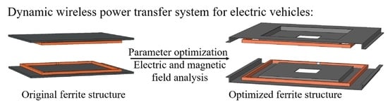
3. Ferrite Core Optimization

To obtain the optimal coupler structure in the dynamic charging mode (the vehicle motion), an efficient methodology is proposed to evaluate the impact of the magnetic part (ferrite core) on the coupling coefficient K. Different topologies of ferrites are studied separately while keeping the same primary and secondary coils, as the ferrite is a low-conductivity material that can be used in several tenth kHz frequency domains [1,3,5,10,11,12].
The magnetic coupler is studied with a 3D FEM model. The finite element approach discretizes the whole studied domain into small finite elements where the electromagnetic fields are interpolated. For calculating the electrical and magnetic fields in the frequency domain, the equation solved by FEM is as follows [26]:
× ( μ 1 × A ) + j w σ A = J e
where A is the magnetic vector potential, J e is an externally generated current density, w is the angular frequency, σ is the electrical conductivity, and μ is the material’s permeability. The coils of the magnetic coupler are modeled as homogenized multi-turn discretized coils, as they are made with Litz wires composed of 1250 strands, and the strand’s diameter is 0.1 mm, which is smaller than the skin depth at the defined frequency. According to the existing pad from the laboratory in Figure 7a, a ferrite structure of rectangular shape has been used as the magnetic part of the system, which will be called the “original ferrite structure” in the following sections. It is defined as 500 mm × 600 mm, as shown in Figure 7. It is made from tiles of ferrite material (25 mm wide and 2 mm thick). The 3C95 material from Ferroxcube [27] is chosen for the system, in which the relative permeability is μ r   3 C 95 = 3000 at 25 °C. Its saturation induction value is about BS ≈ 500 mT, as shown in Figure 7b. Here, the tiles are glued to each other using a non-magnetic resin. Due to the application (EV charging), the space between tiles is neglected in front of the air gap between the primary and the secondary coils. Therefore, this ferrite plate is considered to be homogeneous in the 3D numerical model.
Before using 3C95 ferrite material, the different relative permeabilities of the ferrite plates were considered in the simulation: without ferrite and μ r = 2000 [28]. When the primary coil is fed with a sine current of amplitude 1 A and the frequency is 85 kHz and the secondary coil is in an open circuit, the magnetic flux leakage reaches the maximum value. The corresponding numerical results are presented in Table 2. It is found that, with a high relative permeability of ferrite, the coupling coefficient K improves by 26.1% and the magnetic flux density leakage decreases by 61.8% compared to the case without ferrite. Therefore, 3C95 ferrite material is chosen for this system.
Studies on the different ferrite topologies use the same external dimensions (maximum dimensions of the ferrite plate: 500 mm × 600 mm). The objective is to improve the coupling coefficient between the primary and the secondary pads while ensuring the lowest possible volume of ferrite, reducing the magnetic material costs. The parameters are properties of different ferrite structures, such as ferrite thickness, bosses of the ferrite plates and so on. The objective function is calculated with a uniform distribution of each parameter in its range. Then, the optimal values are selected from them.

3.1. Variation of the External Dimensions of the Ferrite Plate

The first parameter to be studied is the surface (or external dimensions) occupied by the ferrite plate. In this approach, it is meaningful to understand the influence of the ferrite surface on the coupling coefficient. Figure 8 illustrates the simulated geometry, and the dimension of one side of the square-shaped ferrite plate is defined as “S”.
In this part, the “S” parameter varies from 200 mm to 500 mm. Two simulations are carried out: the first is that the ferrite material thickness is constant, equal to that of the original structure (2 mm), and the other is that the ferrite volume is constant, where the thickness of the ferrite material is calculated for each value of the “S” parameter to have a volume equal to that of the original plate. The evolution of the coupling coefficient K as a function of the “S” parameter is presented in Figure 9 when the coils are aligned.
It can be noticed that the coupling coefficient K increases with the surface of the ferrite material, the lines of magnetic fields being better channeled in the presence of this material. At the same time, it can be observed that the thickness of this material has little impact on the coupling coefficient K. To confirm this phenomenon, a study about the influence of the thickness of the ferrite plate is proposed below.

3.2. Thickness Variation of the Ferrite Plate

For the influence of the thickness of the ferrite plate, a ferrite plate with dimensions equal to the original plate (500 mm × 600 mm) is chosen. The variation of the thickness (called the parameter “deptf”) is illustrated in Figure 10.
This “deptf” parameter varies from 2 mm to 20 mm. Figure 11 shows the variation of the coupling coefficient K as a function of the ferrite thickness.
An increase in the coupling coefficient K can be seen with the ferrite thickness increasing. However, K enhances by around 5% when the ferrite thickness is 10 times thicker than before. This leads to the conclusion that the ferrite thickness has little influence on the K, as long as there is no magnetic saturation. During the optimization process, the maximum magnetic flux density in the ferrite is 80 mT, not achieving the saturation value.

3.3. Hole in the Central Part of the Ferrite Plate

References [29,30,31,32] suggested that the central part of the ferrite plate can be removed. Then, Figure 12 shows the corresponding geometry with an empty square in the center. The dimension of this square is marked as “V” (void), which varies between 20 mm and 450 mm.
The variation of the coupling coefficient K with the parameter “V” is given in Figure 13.
Coupling coefficient K decreases when the “V” parameter increases. This means that K decreases with the surface of the ferrite material (as in the case of Section 3.1). Furthermore, below 150 mm, the size of the empty square (the red ellipse plotted in Figure 13) has no impact on the K, but the existence of this hole has the most important advantage, which lies in the lightening of the ferrite plate and the reduction of its cost in raw material. In this way, reducing the amount of ferrite material without significantly altering the coupling coefficient is possible.

3.4. Inner Square Boss of the Ferrite Plate

With the coils being rectangular and positioned at a distance of 8 mm from the ferrite plate, there is an internal volume that can be used to improve the coupling coefficient K. Figure 14 shows the interior square boss of the ferrite plate.
To obtain the size of the interior square boss, a parametric study has come up with varying its dimensions identified by the “BCI” parameter in Figure 14. The height of the boss square remains fixed and equal to 21 mm (corresponding to the sum of the coil thickness and the distance between the coil and the ferrite plate). Then, the performance of the coupling coefficient K as a function of the “BCI” parameter is presented in Figure 15.
It can be found that the value of the coupling coefficient K rises with the “BCI” parameter, and this is up to the value BCI = 350 mm. Beyond this value, K starts to decrease. Indeed, the latter even falls below its original value (original structure presented in Figure 7) when the interior boss is closest to the winding. Thus, there is an optimal value for the dimensions of the internal boss square.

3.5. Bosses at the Edge of the Ferrite Plate

Inspired by the interior boss solution, and after integrating the central recess, a boss is implemented at the edge of the ferrite structure in order to decrease the magnetic flux density leakage at the sides of EVs. This will further improve the coupling coefficient. Figure 16 shows the boss on the extremity of the ferrite plate along the y-axis, corresponding to the direction of displacement of the EVs.
A parametric study was also done by varying the value of the “BBS” parameter (labeled in Figure 16). The height of this “BBS” was the same as that of the inner square boss (in Section 3.4), equal to 21 mm. Figure 17 displays that the coupling coefficient K ranges as a function of the “BBS” parameter.
It is noted that the size of the “BBS” parameter also influences the coupling coefficient K. The optimum coupling can be obtained when the “BBS” is neither too close nor too far from the coils.

3.6. Optimized Structure

According to these various studies above, it is possible to develop a new ferrite geometry, improving the coupling coefficient K. An optimized ferrite structure and its dimensions are given in Figure 18.

4. Discussion

In order to observe the performance of the ferrite structure, the optimized structure and the original structure are compared with their electric and magnetic parameters. Figure 19 shows these ferrite structures developed in the GeePs laboratory.
In Table 3, the experimental results agree well with the simulation results, and the relative error between the simulation and the experiment is around 10%. The optimized ferrite structure offers an improvement of around 26% of the coupling coefficient (improvement estimated for the aligned coupler) compared to the original one.
After, the magnetic flux density leakage distribution is also compared between the optimized ferrite structure and the original ferrite structure. The near-field test bench is shown in Figure 20a [2,22], and the measurement line of the magnetic flux density leakage distribution is 150 mm above the secondary pad in Figure 20b, but when the primary coil is fed with a sine current of the amplitude 1 A and the frequency 85 kHz in the near-field test bench (the secondary coil is in the open circuit for observing the maximum magnetic flux leakage above it), the coils with the optimized ferrite structure have around 9% more magnetic flux density than those with the original ferrite structure at the position of 150 mm above the secondary ferrite, as shown in Figure 20c. Moreover, the ferrite volume is increased by 31% compared to the original ferrite structure.
After, Figure 21 gives the evolution of the coupling coefficient K for these two structures when they have some displacement along the y-axis. In the case of a relative displacement of the axis of the primary and secondary coils, K changes from 0 mm (coaxial coils) to 700 mm. For these two structures, the coupling coefficient K decreases with the displacement increasing, because a less magnetic flux flows through the secondary coil, but the optimized ferrite structure performs better than the original one (before the dotted line in Figure 21b) when the displacement varies from 0 mm to 260 mm, nearly equal to half of the ferrite length.

5. Conclusions and Future Work

This paper proposes a study of different ferrite topologies to improve the system’s efficiency. The maximum system efficiency is mainly related to the coupling coefficient when the resonant frequency and the coils are defined. Therefore, the coupling coefficient is crucial for the system. Moreover, the displacement performance should also be considered for the DWPT system.
According to the analysis of different ferrite topologies, some parameters have the least influence on the coupling coefficient, such as the ferrite thickness, but some parameters can significantly improve the performance of the coupler, such as the surface of the ferrite material. This optimization procedure leads to a new structure, which guarantees an increase in the coupling coefficient compared with the existing structure. Experimental validation was also carried out in this work. Although the optimized ferrite structure has around 31% more volume than the original one, the coupling coefficient has improved by 26%, and it has a better tolerance for displacement along the y-axis (0 mm~260 mm). However, the magnetic flux leakage above the secondary coil with the optimized ferrite structure also increases by 9%. Nonetheless, the inner square boss part of the optimized ferrite design can be used to install the compensation network for saving the system volume in EVs. Future work will be dedicated to the performance of the DWPT system with this optimized ferrite structure and the series–series compensation network at the VEDECOM Institute.
Furthermore, the analysis of different ferrite topologies could give some tips for designing other WPT systems, such as the “A milestone in urban wireless Electric Road Systems” project at Tel Aviv University [34] and the “Electric Road System project” in the city of Balingen [35] and so on [36].

Author Contributions

Conceptualization, K.K., E.L., Y.L.B. and M.B.; methodology, K.K., E.L., Y.L.B. and M.B.; software, K.K. and Y.P.; validation, K.K., M.B. and Y.P.; writing—original draft preparation, K.K., M.B. and Y.P.; writing—review and editing, K.K., Y.P., Y.L.B. and L.P.; supervision, E.L., Y.L.B. and M.B. All authors have read and agreed to the published version of the manuscript.

Funding

This research received no external funding.

Data Availability Statement

No new data were created or analysed in this study. Data sharing is not applicable to this article.

Conflicts of Interest

The authors declare no conflict of interest.

References

  1. Sanguesa, J.A.; Torres-Sanz, V.; Garrido, P.; Martinez, F.J.; Marquez-Barja, J.M. A Review on Electric Vehicles: Technologies and Challenges. Smart Cities 2021, 4, 372–404. [Google Scholar] [CrossRef]
  2. Economic and Environmental Sustainability of Dynamic Wireless Power Transfer for Electric Vehicles Supporting Reduction of Local Air Pollutant Emissions—ScienceDirect. Available online: https://www.sciencedirect.com/science/article/pii/S1364032120308212 (accessed on 7 July 2023).
  3. Kadem, K. Modélisation et Optimisation d’un Coupleur Magnétique Pour la Recharge par Induction Dynamique des Véhicules électriques. Ph.D. Thesis, Université Paris-Saclay, ‎Paris‎, France, 2020. Available online: https://hal.science/view/index/identifiant/tel-03253967 (accessed on 16 July 2023).
  4. Coca, E. (Ed.) Wireless Power Transfer—Fundamentals and Technologies; IntechOpen: London, UK, 2016. [Google Scholar] [CrossRef]
  5. Mohamed, A.A.S.; Shaier, A.A.; Metwally, H.; Selem, S.I. An Overview of Dynamic Inductive Charging for Electric Vehicles. Energies 2022, 15, 5613. [Google Scholar] [CrossRef]
  6. Budhia, M.; Covic, G.; Boys, J. A New IPT Magnetic Coupler for Electric Vehicle Charging Systems. In Proceedings of the IECON 2010—36th Annual Conference on IEEE Industrial Electronics Society, Glendale, AZ, USA, 7–10 November 2010; pp. 2487–2492. [Google Scholar]
  7. Budhia, M.; Boys, J.T.; Covic, G.A.; Huang, C.-Y. Development of a Single-Sided Flux Magnetic Coupler for Electric Vehicle IPT Charging Systems. IEEE Trans. Ind. Electron. 2013, 60, 318–328. [Google Scholar] [CrossRef]
  8. European Commission. Wireless Charging for Electic Vehicles. UNPLUGGED Project|FP7|CORDIS. Available online: https://cordis.europa.eu/project/id/314126 (accessed on 22 February 2021).
  9. Benders, B.; Vermaat, P.; Bludszuweit, H.B.; Theodoropoulos, T. Interoperability Considerations. Available online: http://www.fabric-project.eu/www.fabric-project.eu/images/Deliverables/FABRIC_D33.3_Interoperability_considerations_2017_update.pdf (accessed on 20 July 2020).
  10. Jayalath, S.; Khan, A. Design, Challenges, and Trends of Inductive Power Transfer Couplers for Electric Vehicles: A Review. IEEE J. Emerg. Sel. Top. Power Electron. 2021, 9, 6196–6218. [Google Scholar] [CrossRef]
  11. Ahmad, A.; Alam, M.S.; Chabaan, R. A Comprehensive Review of Wireless Charging Technologies for Electric Vehicles. IEEE Trans. Transp. Electrif. 2018, 4, 38–63. [Google Scholar] [CrossRef]
  12. Thai, V.X.; Choi, S.Y.; Choi, B.H.; Kim, J.H.; Rim, C.T. Coreless power supply rails compatible with both stationary and dynamic charging of electric vehicles. In Proceedings of the 2015 IEEE 2nd International Future Energy Electronics Conference (IFEEC), Taipei, Taiwan, 1–4 November 2015; pp. 1–5. [Google Scholar]
  13. Miller, J.M.; Scudiere, M.B.; McKeever, J.W.; White, C. Wireless power transfer. In Proceedings of the Oak Ridge National Laboratery’s Power Electronics Symposium, Singapore, 5–8 December 2011. [Google Scholar]
  14. COMSOL. Software for Simulating Static and Low-Frequency Electromagnetics. Available online: https://www.comsol.com/acdc-module (accessed on 29 January 2022).
  15. Ibrahim, M. Wireless Inductive Charging for Electrical Vehicles: Electromagnetic Modelling and Interoperability Analysis. Ph.D. Thesis, Université Paris Sud, Paris, France, 2014. Available online: https://theses.hal.science/tel-01127163/document (accessed on 12 July 2023).
  16. Kadem, K.; Cheriet, F.; Laboure, E.; Bensetti, M.; Le Bihan, Y.; Debbou, M. Sensorless Vehicle Detection for Dynamic Wireless Power Transfer. In Proceedings of the 2019 21st European Conference on Power Electronics and Applications (EPE ’19 ECCE Europe), Genova, Italy, 2–5 September 2019; pp. 1–6. [Google Scholar]
  17. SAE International. Wireless Power Transfer for Light-Duty Plug-In/Electric Vehicles and Alignment Methodology; SAE International: Warrendale, PA, USA, 2017. [Google Scholar]
  18. International Electrotechnical Commission. Electric Vehicle Wireless Power Transfer (WPT) Systems—Part 1: General Requirements; International Electrotechnical Commission: Geneva, Switzerland, 2019. [Google Scholar]
  19. International Organization for Standardization. Electrically Propelled Road Vehicles—Magnetic Field Wireless Power Transfer—Safety and Interoperability Requirements; International Organization for Standardization: Geneva, Switzerland, 2018. [Google Scholar]
  20. International Electrotechnical Commission. Interoperability and Safety of Dynamic Wireless Power Transfer (WPT) for Electric Vehicles; International Electrotechnical Commission: Geneva, Switzerland, 2021. [Google Scholar]
  21. Debbou, M.; Colet, F.; Kadem, K. Wireless Inductive Power Transfer: Design and Control for an Optimal Operation. In Proceedings of the 2018 20th European Conference on Power Electronics and Applications (EPE’18 ECCE Europe), Riga, Latvia, 17–21 September 2018; pp. 1–8. [Google Scholar]
  22. Kadem, K.; Benyoubi, F.; Bensetti, M.; Bihan, Y.L.; Labouré, E.; Debbou, M. An Efficient Method for Dimensioning Magnetic Shielding for an Induction Electric Vehicle Charging System. Prog. Electromagn. Res. 2021, 170, 153–167. [Google Scholar] [CrossRef]
  23. Kadem, K.; Bensetti, M.; Le Bihan, Y.; Labouré, E.; Debbou, M. Optimal Coupler Topology for Dynamic Wireless Power Transfer for Electric Vehicle. Energies 2021, 14, 3983. [Google Scholar] [CrossRef]
  24. Robert, W.E.; Dragan, M. Fundamentals of Power Electronics, 2nd ed.; Springer: New York, NY, USA, 2001. [Google Scholar]
  25. Boys, J.T.; Covic, G.A. IPT Fact Sheet Series: No. 2 Magnetic Circuits for Powering Electric Vehicles. 2014. Available online: https://www.qualcomm.com/content/dam/qcomm-martech/dm-assets/documents/ipt_fact_sheet_2_-_uoa_2014.pdf (accessed on 16 July 2023).
  26. COMSOL. Documentation. Available online: https://doc.comsol.com/6.1/docserver/#!/com.comsol.help.acdc/acdc_ug_theory.05.51.html (accessed on 7 July 2023).
  27. FERROXCUBE. 3C95 Material Specification. Available online: https://www.ferroxcube.com/upload/media/product/file/MDS/3c95.pdf (accessed on 16 July 2023).
  28. TDK. N27 Ferrite Datasheet. Available online: https://www.tdk-electronics.tdk.com/download/528850/3a7f957d754f899aec42cd946598c5c4/pdf-n27.pdf (accessed on 16 July 2023).
  29. Elghanam, E.A.; Kabalan, H.H.; Hassan, M.S.; Osman, A. Design and Modeling of Ferrite Core Geometry for Inductive Wireless Chargers of Electric Vehicles. In Proceedings of the 2019 International Conference on Electrical and Computing Technologies and Applications (ICECTA), Ras Al Khaimah, United Arab Emirates, 19–21 November 2019; pp. 1–5. [Google Scholar]
  30. Hu, M.; Madawala, U.K.; Baguley, C. The Optimal Placement of Ferrite in Inductive Power Transfer Coupling Pads. In Proceedings of the 2021 IEEE 12th Energy Conversion Congress & Exposition—Asia (ECCE—Asia), Singapore, 24–27 May 2021; pp. 469–474. [Google Scholar]
  31. Carretero, C.; Lope, I.; Acero, J. Magnetizable Concrete Flux Concentrators for Wireless Inductive Power Transfer Applications. IEEE J. Emerg. Sel. Top. Power Electron. 2020, 8, 2696–2706. [Google Scholar] [CrossRef]
  32. Choi, B.-G.; Kim, Y.-S. New Structure Design of Ferrite Cores for Wireless Electric Vehicle Charging by Machine Learning. IEEE Trans. Ind. Electron. 2021, 68, 12162–12172. [Google Scholar] [CrossRef]
  33. Debbou, M.; Kadem, K.; Labouré, E.; Le Bihan, Y.; Bensetti, M. Inductive Coupler and Magnetic Induction Charging System for Electric and Hybrid Vehicles. FR3094832A1, WO2020208313A1. Available online: https://patentscope.wipo.int/search/en/detail.jsf?docId=WO2020208313 (accessed on 5 June 2023).
  34. Tel Aviv University Station. Available online: https://electreon.com/projects/tel-aviv (accessed on 11 June 2023).
  35. McFadden, C. A New Wireless EV Charging Road Is Currently under Construction in Germany. Available online: https://interestingengineering.com/innovation/germany-first-public-ev-charging (accessed on 11 June 2023).
  36. Zarazaga, S. Innovative Charging in Electric Vehicle Solutions to Be Tested in Europe; INCIT-EV Project. 2020. Available online: https://www.incit-ev.eu/news-title/ (accessed on 16 July 2023).
Figure 1. Typical WPT system for EVs.
Energies 16 05439 g001
Figure 2. DWPT system of an electric vehicle [2,16].
Energies 16 05439 g002
Figure 3. VEDECOM DWPT system test bench [21].
Energies 16 05439 g003
Figure 4. The existing pad from the DWPT system [2,22].
Energies 16 05439 g004
Figure 5. Magnetic coupler dimensions [2].
Energies 16 05439 g005
Figure 6. Equivalent electrical circuit in the SS compensation topology [2,10,11,15,22,23].
Energies 16 05439 g006
Figure 7. Original ferrite structure [2,22]: (a) original ferrite structure view; (b) BH curve of 3C95 ferrite material [27].
Energies 16 05439 g007
Figure 8. Variation of the ferrite surface.
Energies 16 05439 g008
Figure 9. Coupling coefficient K in the function of “S”.
Energies 16 05439 g009
Figure 10. Variation of the ferrite thickness “deptf”.
Energies 16 05439 g010
Figure 11. Coupling coefficient K as a function of the ferrite thickness.
Energies 16 05439 g011
Figure 12. Variation of the parameter “V” in the ferrite plate.
Energies 16 05439 g012
Figure 13. Coupling coefficient K as a function of the side of the empty square.
Energies 16 05439 g013
Figure 14. Internal square boss: (a) coupler view; (b) primary view.
Energies 16 05439 g014
Figure 15. Coupling coefficient K as a function of the side of the inner boss square.
Energies 16 05439 g015
Figure 16. Boss on the extremity: (a) coupler view; (b) primary view.
Energies 16 05439 g016
Figure 17. Coupling coefficient K in the function of the “BBS” parameter.
Energies 16 05439 g017
Figure 18. Optimized ferrite structure: (a) optimized ferrite structure view; (b) structure and dimensions of Section 1; (c) structure and dimensions of Section 2.
Energies 16 05439 g018
Figure 19. Ferrite structures developed in the GeePs laboratory: (a) original ferrite structure; (b) optimized ferrite structure [33].
Energies 16 05439 g019
Figure 20. Comparison of the magnetic flux density between the original ferrite structure and optimized ferrite structure: (a) near-field test bench; (b) measurement line; (c) comparison of the magnetic flux density leakage on the measurement line between the original ferrite structure and optimized ferrite structure.
Energies 16 05439 g020
Figure 21. Comparison of the coupling coefficient K between the original ferrite structure and optimized ferrite structure: (a) displacement along the y-axis; (b) comparison of the coupling coefficient K between the original ferrite structure and optimized ferrite structure along the y-axis.
Energies 16 05439 g021
Table 1. Parameters of the magnetic coupler [2].
ParametersValues (Unit)
Air gap A150 (mm)
Ferrite thickness Deptf2 (mm)
Coil thickness Depc13 (mm)
Ferrite length Lf600 (mm)
Ferrite width Wf500 (mm)
Coil external length Lou468 (mm)
Coil internal length Lin442 (mm)
Table 2. Numerical results of the magnetic coupler with different ferrite relative permeabilities.
Ferrite Relative PermeabilitySelf-Inductance L (µH)Mutual Inductance M (µH)Coupling Coefficient KMagnetic Flux Density on the Surface Center of the Secondary Pad (µT)
0
(without ferrite)
46.57.810.177.93
200063.713.40.213.18
300065.815.00.233.03
Table 3. Comparison of the electrical parameters between the rectangular coils with the original ferrite structure and with the optimized ferrite structure.
SimulationSelf-Inductance L (µH)Mutual Inductance M (µH)Coupling Coefficient K
Original ferrite structure63.713.40.21
Optimized ferrite structure72.518.90.26
ExperimentSelf-Inductance L (µH)Mutual Inductance M (µH)Coupling Coefficient K
Original ferrite structure58.512.10.20
Optimized ferrite structure69.918.90.27
Relative difference between the original and optimized ferrite structure16.3%36.0%25.9%
Disclaimer/Publisher’s Note: The statements, opinions and data contained in all publications are solely those of the individual author(s) and contributor(s) and not of MDPI and/or the editor(s). MDPI and/or the editor(s) disclaim responsibility for any injury to people or property resulting from any ideas, methods, instructions or products referred to in the content.

