Review

Noise in Electric Motors: A Comprehensive Review

by
Patxi Gonzalez
1,
Garikoitz Buigues
2 and
Angel Javier Mazon
2,*
1
Obeki Innobe AIE, Baratzondo 3, Pol. Apatta—Erreka, 20400 Ibarra, Spain
2
Department of Electrical Engineering, Faculty of Engineering in Bilbao, University of the Basque Country (UPV/EHU), 48013 Bilbao, Spain
*
Author to whom correspondence should be addressed.
Energies 2023, 16(14), 5311; https://doi.org/10.3390/en16145311
Submission received: 30 May 2023 / Revised: 28 June 2023 / Accepted: 7 July 2023 / Published: 11 July 2023
(This article belongs to the Topic Future Generation Electric Machines and Drives)

Abstract

:
Electric machines are important devices that convert electrical energy into mechanical energy and are extensively used in a wide range of applications. Recent years have seen an increase in applications where electric motors are used. The frequent use of electric motors in noise-sensitive environments increases the requirements placed on electric motors intended for these applications, especially when compared to electric motors commonly used in industrial applications. This paper provides a comprehensive review of electric motor noise. Firstly, a brief introduction to noise is given. Then, the sources of electromagnetic noise and vibration in electric machines, including mechanical, aerodynamic and electromagnetic factors, are presented. Different methods such as analytical, numerical and semi-analytical for calculating electromagnetic force, natural frequencies and noise are also analyzed. Various methods for noise reduction are presented, including skewing, stator and rotor notching and slot opening width. Finally, noise measurement standards and procedures are described.

1. Introduction

With the development in power electronics and motor and generator control technologies, recent years have seen an increase in applications where electric motors are used to replace older systems based on combustion engines or hydraulic systems.
This increasing electrification has led to more and more electrical, electromagnetic and electronic equipment being installed in locations where low acoustic noise generation is a determining factor. This growing use of electric motors in noise-sensitive environments means that the requirements imposed on electric motors intended for these applications are higher than those applied to electric motors used for industrial applications. Therefore, developing motors that guarantee low acoustic noise generation is becoming an increasing necessity.
This article conducts a comprehensive literature review in the subject. Section 2 provides a concise introduction to noise, followed by an examination of the origins of electromagnetic noise and vibration in electrical machines, considering both mechanical and electromagnetic factors in Section 3. Section 4 presents various approaches for calculating electromagnetic force, natural frequencies, and noise. Lastly, Section 5 provides different techniques for mitigating noise and Section 6 describes noise measurement standards and procedures.

2. Acoustics and Noise Principles

2.1. Decibel Unit, Types A, B and C

Sound is defined as the sensation produced in the organ of hearing by the vibratory motion of bodies transmitted by an elastic medium such as air. The sound that the human ear is capable of detecting ranges from 20 to 20,000 Hz. Although decibel (dB) is the most frequently unit used for measuring sound, watts (W) are also sometimes used when describing sound power. The decibel is a logarithmic ratio between two known quantities.
How the human ear perceives sound depends on both the amplitude and the frequency at which it is produced. Since humans are only capable of hearing a defined frequency band of approximately 20 Hz to 20,000 Hz, sound may occur at frequencies outside that band without being perceived by humans.
Weighting systems have been developed to adjust the level of specific frequencies in order to more accurately reflect their impact on human perception, as well as to provide more meaningful sound pressure data. Nowadays, the most common weighting scale in use is “A” weighting. Sound pressure readings at this scale are typically indicated as dBA. Despite its popularity in industrial specifications, this scale is intended to be applied to sounds with a relatively low intensity of approximately 100 dB or less [1].
The steady-state raw gains for A-weighting can be calculated using Equations (1) and (2) below [1].
R A ( f ) = 12200 2 f 4 ( f 2 + 20.6 2 ) ( f 2 + 12200 2 ) f 2 + 107.7 2 ( f 2 + 737.9 2 )
where f = frequency (Hz).
Standard practice dictates that the weighting has to be normalized to 1000 Hz. Therefore, the final gain (A) can be determined by the following equation.
A = 2.00 + 20 log R A ( f )

2.2. Audible Spectrum. Octaves

The audible spectrum is the range of sound frequencies capable of being detected by the human ear. This spectrum is between 20 Hz and 20,000 Hz. Below 20 Hz would be infrasound and above 20,000 Hz would be ultrasound.
To analyze sound, the most common approach is to group data into octave bands. Each band covers a frequency range of 2:1 centered on established points, and they are bounded by cutoff frequencies above and below the center frequency. For instance, the 250 Hz octave band contains all sound pressure data from 177 Hz to 354 Hz. The center and cutoff frequencies for the full octave bands are shown in Table 1 below.

2.3. Acoustic Pressure and Acoustic Power

Sound power (П) is defined by the following equation [2]:
П = S I d S = S I r d S = S p u r ¯ d S
where I is the intensity vector (rate of energy flow per unit area), S is the surface enclosing the noise source, Ir is the component of the intensity vector normal to S, p is the sound pressure, ur is the particle velocity normal to S, and the overbar represents the time average.
Sound pressure, also known as acoustic pressure, can provide valuable information about how humans perceive noise. It is important to note that, unlike sound power, the sound pressure level measured for a sound source can be influenced by the surrounding environment. While the total sound power generated by a vibratory source is independent of its environment, it cannot be measured directly. For this reason, sound level meters can measure sound power based on sound pressure readings.
Furthermore, in recent times, it has been observed that some authors have shown interest in analyzing additional parameters when measuring noise, in addition to sound power and sound pressure. These parameters are “Loudness”, “Roughness”, “Sharpness” or “Fluctuation strength” among others [3]. They indicate the perception of pleasantness or unpleasantness that a particular sound can produce.

2.4. Standards

Regarding electric motors, the International Electrotechnical Commission (IEC) has established a standard that governs the maximum allowable levels based on the type of machine and its output power. This standard is applicable to noise and vibrations that all electrical machine design must comply with:
  • IEC 60034-9: Noise limits on rotating electrical machines.
  • IEC 60034-14: Mechanical vibrations.
The object of the IEC 60034-9 standard is to determine the maximum A-weighted sound power levels, LwA in decibels, for airborne noise emitted by rotating electrical machines of standard designs, as a function of power, speed and load. The object of the IEC 60034-14 standard is to specify the factory acceptance vibration test procedures and vibration limits for electric machines uncoupled from any load or prime mover.
In addition to these standards, there are others that regulate the measurement of sound pressure, such as:
  • ISO 1680: Test code for the measurement of airborne noise emitted by rotating electrical machinery.
  • ISO 3740: Determination of sound power levels of noise sources. Guide for the use of basic standards.
The ISO 1680 standard specifies all the information necessary to carry out efficiently and under standardized conditions the determination, declaration, and verification of the noise emission characteristics of rotating electrical machines. It specifies noise measurement methods that can be used, and specifies the operating and mounting conditions required for the test. The ISO 3740 standard gives guidance for the use of a set of twelve basic International Standards describing various methods for determining sound power levels from all types of machinery, equipment and products.

3. Noise Sources in Electric Motors

Electric motors primarily consist of two essential components: a stator and a rotor, with the space between them known as the airgap. Additionally, there are several other crucial elements to consider, including endshields, a housing, a shaft, and a cooling system, which may involve components such as fans or water jackets.
Taking the previous components into consideration, three main types of noise sources can be distinguished in electric motors:
  • Of aerodynamic origin,
  • Of mechanical origin, and
  • Of electromagnetic origin.
The electromagnetic noise in electric motors, sometimes called electrical noise, is primarily caused by the magnetic field in the air gap. Mechanical noise is mainly generated by bearings, rotor-stator eccentricity, and mechanical imbalance. Lastly, aerodynamic noise is the noise produced by the motor’s ventilation and cooling system. Some references [4] also distinguish noise of electronic origin, as a consequence of electric motors fed by electronic converters.

3.1. Mechanical and Aerodynamic Noise

Several authors have analyzed the aerodynamic noise in electric motors [5,6,7]. It is expected that the noise level will increase as the speed of the motor’s cooling fan increases. According to [6], electromagnetic noise is more dominant at low speeds, while aerodynamic noise is more dominant at high speeds. To demonstrate this, the motors are slowly run up to 3300 rpm and the sound pressure is measured. The same measurement is repeated once the motor is running at 3300 rpm, but with the power turned off.
This type of noise is unaffected by motor load. The level of aerodynamic noise remains the same whether the motor is running at full load or with no load at all.
The International Electrotechnical Commission (IEC) has defined the degree of protection against mechanical damage and environmental factors, such as moisture or corrosive vapors, in the standard IEC60034-5. The designation for the degree of protection is denoted by the letters “IP” followed by two numbers. For example, a motor labeled as IP23 indicates that it is open to the surrounding environment, while a motor designated as IP55 suggests that it is enclosed and protected. In this regard, noise levels differ depending on whether the motor is open (IP23) or closed (IP55). The ventilation noise emitted by open motors is significantly higher than that of closed motors, as the rotor generates less noise when enclosed. This also applies to noise generated within the motor, whether of electromagnetic or mechanical origin. Therefore, in order to minimize noise levels, it is recommended to design motors that are as closed as possible (IP55).
There are several sources of mechanical noise, such as bearings, eccentricity between rotor and stator, and mechanical unbalance. In [8], the influence of manufacturing tolerances has even been analyzed. It should be noted that the noise caused by rotor eccentricity can also be considered as a type of electromagnetic noise, since the imbalance of electromagnetic forces caused by the eccentricity leads to increased noise.
In [9,10,11] the influence of rotor eccentricity on motor noise has been analyzed. According to [11], four types of eccentricities are distinguished (as can be seen in Figure 1):
When the stator and rotor are not regular cylinders, their shape deviation can produce air gap eccentricity, as in Figure 1a. Another very important, and widely analyzed, type of air gap eccentricity is that the rotor axis does not coincide with the stator axis, as in Figure 1b–d. When the rotor axis is straight, the eccentricity can be divided into parallel eccentricity, Figure 1b, and inclined eccentricity, Figure 1c. When the rotor shaft is bent, the eccentricity type is called curved, as in Figure 1d.
Test measurements [9,10] demonstrate that eccentricities between rotor and stator lead to an increase in the noise level generated by motors. Another interesting conclusion obtained by [12] is that the minimum achievable noise is highly dependent on the eccentricity value, but the dimensions required for the motor to have the lowest noise level are independent of any type of eccentricity.

3.2. Electromagnetic Noise

Electromagnetic fields result in forces that cause structural vibrations. The magnitude of the vibrations depends on the amplitudes and especially on the frequencies of the forces, and they must not coincide with the natural frequencies of the system. These surface oscillations then cause a conversion from vibrational energy to sound energy.

3.2.1. Electromagnetic Forces

There are two types of forces behind noise of electromagnetic origin occurring in electrical machines: magnetostriction forces and Maxwell forces. In radial-flow rotating machines, the main structural modes of interest for acoustic noise are those that involved radial vibration waves of the yoke (circumferential modes), which are generally the most efficient ones for radiating acoustic noise. Both magnetostriction and Maxwell forces can generate radial deflections of the stator yoke [13].
According to [2], obtained from Maxwell’s Tensor, the radial magnetic forces per unit area are given by Equation (4):
F = B r 2 B t 2 2 μ 0
where F is the force per unit area, Br is the radial component of the magnetic flux, Bt is the tangential component and µ0 is the magnetic permeability of the vacuum.
The radial force generated within the motor induces vibrations in the stator, which subsequently result in the emission of noise by the motor to its surroundings.
There are many references that analyze the forces of electromagnetic origin [14,15,16,17,18,19,20,21,22,23] but, in most publications, it is common to neglect the tangential component, since it is much smaller than the radial component. In contrast, the authors of [16] show that this assumption is not always valid and that, when the orders of the harmonics of the radial and tangential field are the same, ignoring the tangential component can change the amplitude of these harmonics. According to [23], neglecting the tangential component results in a calculation error that can be about 2 dB. These tangential forces have a greater influence when the ratio of stator yoke to tooth length is small. Therefore, it must be taken into account in machines with high pole pairs.

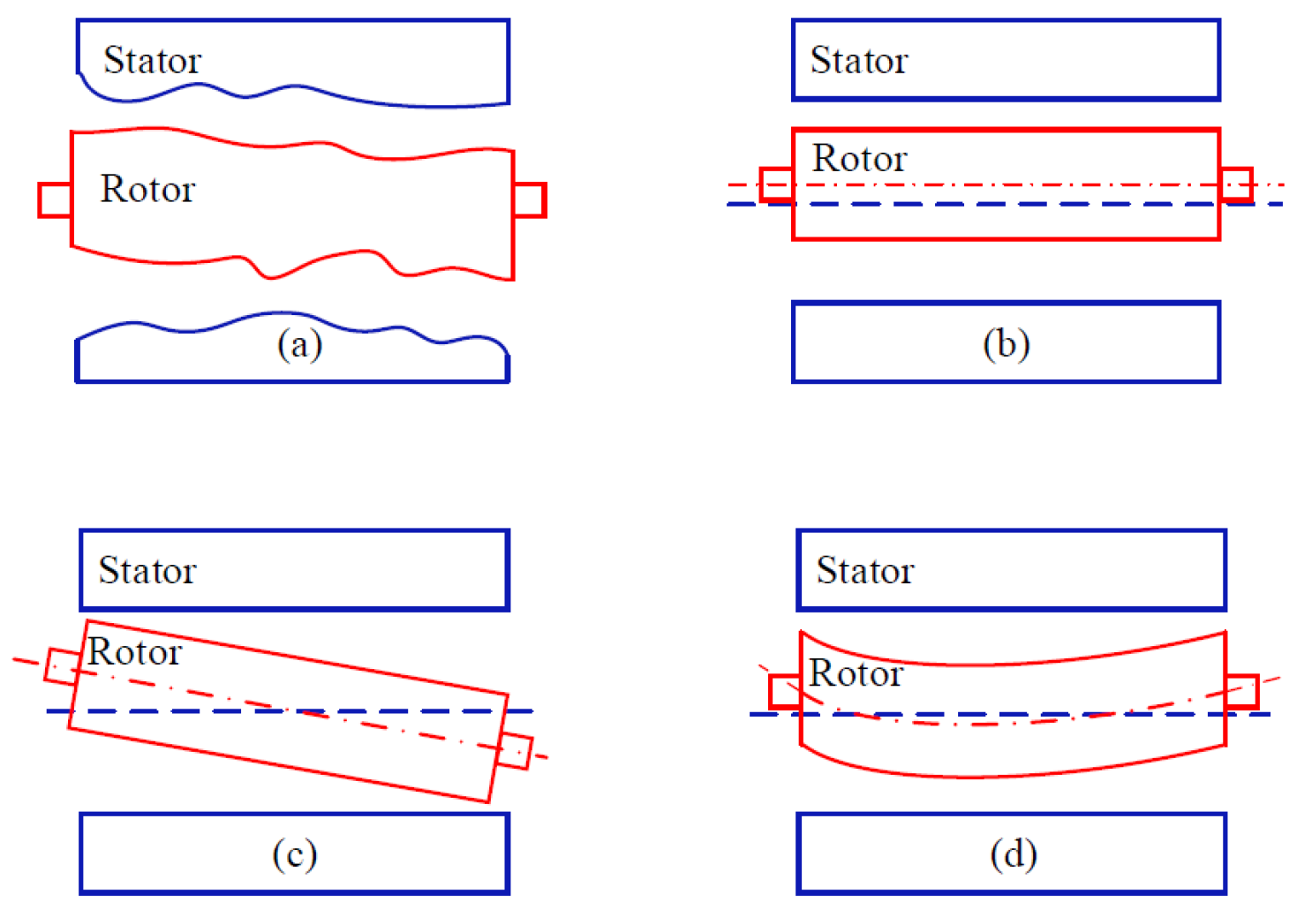
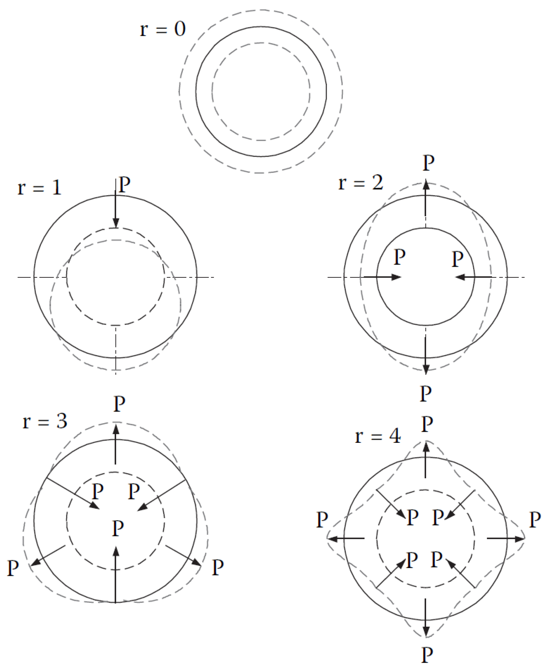
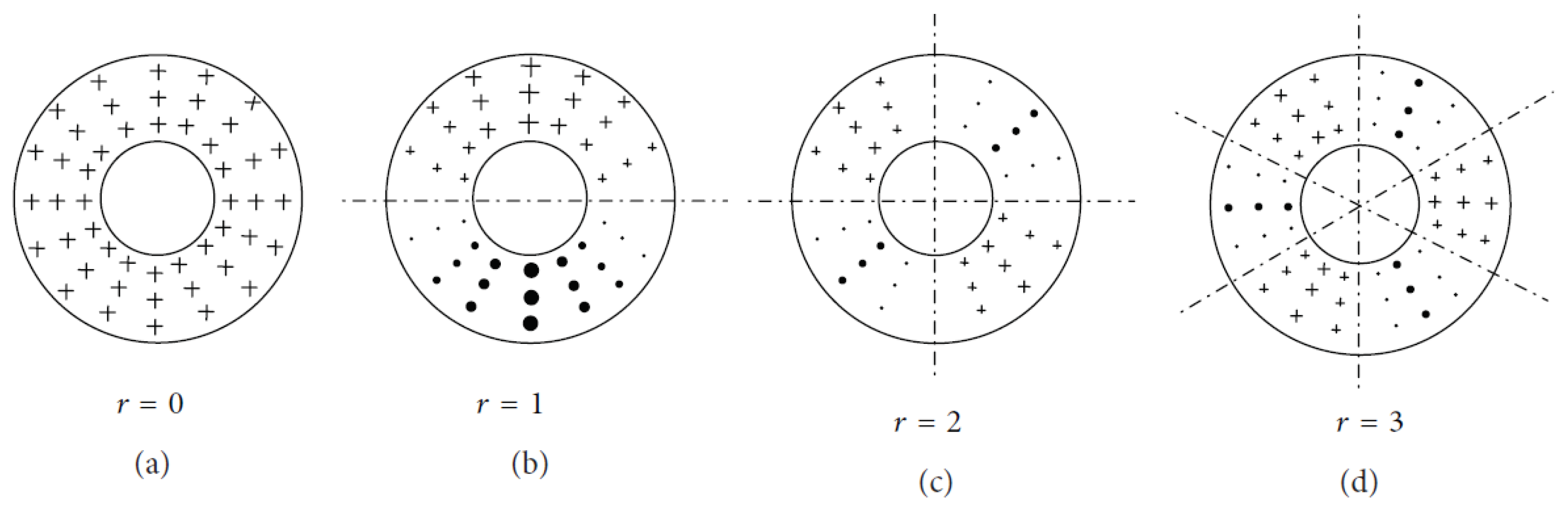
3.2.2. Natural Frequencies and Vibration Modes

It is crucial to consider both force frequencies and natural frequencies of the stator system when designing electric rotating machinery because, as mentioned in [5], the vibration and resulting noise level are at their highest when the frequency of the magnetic force is equal or close to the natural frequency of the stator system.
Natural frequencies are associated with different vibration modes (0, 1, 2, ...) and the lower modes are the ones that contribute the most to the increase in electromagnetic noise. Figure 2 shows the spatial distribution of forces producing vibration modes of different orders (r = 0, 1, 2, 3, 4).
Generally, the mode of the force has the greatest impact on vibration and noise behavior, followed by the frequency of the force, and lastly the amplitude of the force [24].
Typically, natural frequencies of the motor stator are calculated without considering the influence of its winding. However, the author of [25] was one of the first researchers to analyze the impact of winding and different varnishes used in stator impregnation on natural frequency.
Since natural frequency is associated with the mechanical stiffness of the stator, some authors have investigated the influence of different magnetic sheet materials on motor noise emission. In [26], the effect of grain-oriented versus non-grain-oriented magnetic sheet on squirrel cage motor stator construction was analyzed, concluding that grain-oriented magnetic sheets produce lower noise.
Additionally, when the motor is in thermal equilibrium, the stator temperature is higher during continuous operation than at rest, and this temperature difference can affect its natural frequency [27].
Finally, it is worth mentioning that neglecting the influence of motor endshields on the natural frequency of the system may result in errors of up to 25% [28].

3.2.3. Power Supply Control of the Electric Motor

The use of electric motors fed by variable frequency drives is becoming more common, often replacing hydraulic motors. However, since these motors are not fed with sine waves, they tend to generate higher levels of noise [8,29,30,31].
One of the most analyzed parameters by researchers is the switching frequency. In [32,33], the noise emitted by the same motor is analyzed when different switching frequencies of the frequency converter are used. At low frequencies, a higher switching frequency results in lower machine noise, but for high frequency operation (100 Hz) the differences are negligible.
Space Vector PWM (SVPWM) technique is the most widely used power supply strategy in variable frequency drives because of its reduced harmonic distortion (THD) [34]. However, one of the main disadvantages of this technique is that harmonics and noise are concentrated around the inverter switching frequency value and its multiples [35,36].
If the frequency of these harmonics coincides with the natural frequency of the motor, the noise will increase considerably. Therefore, from the early stages of design, it is convenient to pay special attention to the vibration modes and natural frequencies, as explained in the previous section.
Recently, the trend has been to look for other power supply methods, different from SVPWM, that achieve noise reduction [37]. For example, the authors of [38] present a triangular modulated signal to reduce noise versus the traditional PWM. The difference of the triangular periodic frequency carrier compared to the traditional PWM is that the switching frequency is variable and, with a variable switching frequency signal, a sinusoidal signal with lower harmonic distortion is obtained.
In addition, the authors of [3] discuss different power supply techniques within the triangular signals. All of them are difficult to be applied in standard variable frequency drives.

3.2.4. Winding Influence

The influence of the winding type on noise generation in electric motors has been extensively researched over the years, considering different options such as single and double layer windings, fractional and integer windings, concentric and concentrated windings and, finally, the winding pitch.
In [39,40,41], the difference between single- and double-layer windings is analyzed, and the main conclusion is that double layer windings perform better against noise generation. Furthermore, according to [9], the higher the number of parallel paths in the winding, the lower the noise produced by the motors.
Regarding integer or fractional windings, different winding configurations for a 20-pole magnet machine are analyzed in [41]. In fact, one integer and 4 fractional winding configurations are analyzed. One of its conclusions is that fractional windings present a greater imbalance in the radial magnetic forces in the air gap. Alternatively, the most significant force in permanent magnet motors (PMMs) with integer windings is the 0-order force, whereas in PMMs with fractional windings is the lowest non-zero-order force [42].
As for concentrated windings, these types of windings present greater problems from the noise and vibration point of view than distributed windings [43] (such as concentric windings). The high harmonic content of the magnetomotive force is the source of the problems.
In [44], the authors propose a new star-delta connected concentric winding configuration, reducing the noise level by 10 dB(A). Finally, the author of [45] shows that short-pitched windings have a lower noise level than windings without shortened pitch.

3.2.5. Noise in Induction Motors

In the case of induction motors, the magnetic field is generated by the stator, which induces a magnetic field in the rotor following the one generated by the stator. Regarding the harmonics present in squirrel cage motors, these can be reduced to three families [46]: slotting force harmonics, “winding force” harmonics, and saturation force harmonics.
Therefore, the design of the stator and rotor slots directly affects the harmonics and acoustic characteristics of the motors. For example, closed rotor slots result in lower noise levels [47] since rotor slotting force harmonics are partially eliminated.
For many years, the stator–rotor slot combination, and its influence on slot harmonics, has been a widely studied parameter in squirrel-cage motors. The proper selection of the number of stator and rotor slots for noise reduction was first proposed by [48]. In recent times, the authors of [49] have presented updated rules and a compilation of previously published research. The number of poles is another aspect related to the number of slots. According to [50], the higher the number of poles, the higher the electromagnetic noise will be.
One of the major advantages of squirrel cage motors fed by frequency inverters is their wide speed range. However, as this range increases, it is inevitable that the speed coincides, or at least passes through, a structural mode of the machine, making it possible for resonances to appear [45].
Furthermore, as discussed in Section 3.2.1, neglecting the tangential component may lead to errors in the calculation of the noise level in squirrel cage motors [23].
Another important aspect in induction motors is the influence that temperature has on the noise emitted. In this regard, the authors of [6] conclude that there is a temperature dependence and, as the temperature of the motor increases, both the natural frequency of the eigenmode and the amplitude of the sound pressure level decrease.

3.2.6. Noise in PMMs

In the case of PMMs, the magnetic field is generated by the magnets of the rotor following the rotating magnetic field generated by the stator. Within the topology of permanent magnet synchronous motors there are mainly two types, depending on where the magnets are placed: Surface Permanent Magnet motors (SPM) and Interior Permanent Magnet motors (IPM).
A review on vibration and noise in PMMs with concentrated windings is presented in [43]. Among the two synchronous motor topologies mentioned above, the IPM emits higher noise when the winding is concentrated [51].
Unlike in induction motors, the cogging torque that is generated by the interaction between the magnets and the magnetic sheet of the stator has to be taken into account in PMMs. Having said that, low cogging torque does not necessarily imply that the motor is less noisy [52].
As in squirrel-cage motors, neglecting tangential versus radial forces can lead to errors in obtaining the noise level [53].
For the same number of poles, increasing the number of slots increases the harmonic amplitudes. As a consequence, configurations with a lower number of slots will be less noisy, as long as the mechanical configuration is similar [54].
The influence of the shape of magnets on the noise emitted by electric motors is something worth considering. Researchers such as [55] have analyzed the impact of the magnet edge shape on the magnetic force and its frequency components. Modifying the edge of the magnet can shift the frequencies to higher orders of the frequency spectrum, reducing the acoustic level. However, this is only effective if the new frequencies do not coincide with any natural frequency of the system. Furthermore, this same effect can be achieved by acting on the pole shape [56], in particular, on the pole width. The forces in the air gap are reduced by enlarging the air gap at the ends of the tooth tips.

3.2.7. Noise in AFMs

Axial flux motors (AFMs) are designed with at least one disk-shaped rotor and one ring-shaped stator, resulting in a flat and uniformly spaced air gap along the axial axis. The term “axial” in the name of the motor refers to the direction of the magnetic flux, which is parallel to the axis of rotation. This type of motor can be configured either with permanent magnets or squirrel cage, although PMMs are more widely used.
The axial magnetic force is what generates vibrations and noise in this motor topology [42,57,58]. Moreover, in permanent magnet synchronous motors, another source of noise is cogging torque and torque ripple [59,60]. These torques generate vibrations in the housing and, consequently, noise emission.
The AFM topology offers a significant advantage over radial flux topology in permanent magnet synchronous motors, since its lower cogging torque reduces the noise level [61,62]
Although the main cause of noise is the axial force, tangential forces are also present in this type of motor. Ref. [61] states that neglecting these components hardly affects the sound power calculation, demonstrating it through simulation.
Although the machine topology is different, the electromagnetic forces obtained from Maxwell’s Tensor are expressed in the same way as for the radial flux topology [61,63], neglecting the tangential component:
F = B z 2 2 μ 0
where F is the force per unit area, Bz is the axial component of the magnetic flux and µ0 is the magnetic permeability of the vacuum.
Unlike radial flux motors, in which the circumferential modes were predominant, the normal modes will be predominant in AFMs. Therefore, the distribution of forces of electromagnetic origin, from order 0 to the third order, would be as shown in Figure 3.
Another aspect to consider for this type of machines is that the natural frequency of mode 0 is usually the lowest, unlike radial flux motors [61]. Consequently, low noise pole/slot combinations in radial flux motors can induce high noise in AFMs [42,61]. The fact that the 0th-order frequency is the lowest implies that, from the early design stages, it can be increased by acting on the mechanical design of the motor casing and covers. It is of the utmost importance that the natural frequency of the motor does not coincide with that of the electromagnetic force, in order to avoid undesired resonances.

4. Modeling, Analysis, and Calculation of Noise in Electric Motors

It is crucial to foresee the behavior of an electric motor before it is manufactured and it is very important to have the necessary tools and methodologies during the early stages of design. Several tools are available to perform noise and vibration calculations in relation to electric motors:
  • Analytical calculations,
  • Numerical calculations, and
  • Semi-analytical calculations.
Analytical calculations can provide faster results, but numerical methods are usually more accurate because structural details can be modeled.

4.1. Natural Frequencies

One of the first calculations necessary to obtain the noise level in electric motors is the calculation of natural frequencies of the system and modal analysis.
A large number of references can be found that conduct finite element simulations to perform modal analysis and calculate natural frequencies. However, a common challenge with these simulations is the significant processing time required. In response to this issue, some authors have developed analytical calculation methods that effectively reduce these processing times. Remarkably, the difference between the results obtained from these analytical methods and experimental measurements is generally minimal [64]. Table 2 shows some of the references that calculate the natural frequencies of motors, including the calculation methods used, mentioning if they verify the calculation results by testing, as well as some interesting remarks.
According to [2], the natural frequencies of modes 0, 1 and m can be analytically calculated. This way, the natural frequency of mode 0 is given by:
f 0 = 1 π D c E c ρ c k i k m d
where Dc is the mean diameter, Ec is the elasticity modulus of the stator material, ρc is the density of the stator material, ki is the stacking factor, and kmd is the mass addition factor defined as:
k m d = 1 + M t + M w + M i M c
where Mt is the mass of all stator teeth, Mw is the mass of stator windings, Mi is the mass of insulation, and Mc is the mass of the stator yoke.
The natural frequency of mode 1 would be:
f 1 = 1 π D c E c ρ c k i k m d 2 1 + k 2 k m r o t k m d
where k:
k = h c 3 D c
where hc is the stator yoke height and kmrot is the mass addition factor for rotation, defined as:
k m r o t = 1 + s 1 c t L i h t 2 π D c I c 1 + M w + M i M t ( 4 h t 2 + 6 h c h t + 3 h c 2 )
where s1 is the number of teeth or slots, ct is the tooth width, Li is the effective length of the stack, ht is the height of the tooth, and Ic is the moment of inertia defined as:
I c = h c 3 L i 12
Finally, the natural frequency of order m:
f m = f 0 k m ( m 2 1 ) m 2 + 1 k a F m
where ka > 1 represents the covers and housing support (legs or flange) and Fm is:
F m = ( 1 + k 2 m 2 1 [ m 2 4 + k m r o t / k m d + 3 ] m 2 + 1 ) 1 / 2
In relation to previous analytical natural frequency calculations, the authors of [67] propose an improved analytical calculation method. It involves adding a material with a mass and stiffness equivalent to the stator teeth and winding, in order to reduce the calculation error in traditional analytical methods.
The abovementioned equations are applicable for radial flux motor stators. For AFMs, the authors of [65] present an analytical equation for the calculation of the natural frequency (fn):
f n = B k C h C s C w 2 π E c ( L i / 2 ) 2 ρ c d 4 ( 1 σ 2 )
where Bk is the boundary condition coefficient, Ch is the stator hollow modification coefficient, Cs is the slot opening modification coefficient, Cw is the modification coefficient due to the winding, d is the stator radius, and σ is the Poisson’s coefficient of the stator material.
The problem with Equation (14) is that the calculation errors with respect to the natural frequencies measured by experimental methods are quite important. In contrast, the authors of [60] also present an analytical formulation for the calculation of natural frequencies of axial flow stators and the results with respect to test measurements are much accurate.
According to [70], the zero-order natural frequency of the disk-shaped housing in AFMs is the lowest, so the zero-order force will be important for vibration and noise generation in such a motor topology. Radial flux motors do not exhibit this characteristic.
Regarding numerical methods, there are several commercial software packages that allow calculating the natural frequencies, by means of 3D finite element methods (FEM). The accuracy of the results obtained by FEM usually depends on the number of elements used in the simulation. This type of calculations is frequently used in advanced design phases, because the computational time is considerably high.
Another way to obtain the natural frequencies of the stator is by using experimental methods, but the main drawback of these methods is that they do not allow design changes to modify these natural frequencies. The most widely used and economical method is the impact hammer excitation method [64].

4.2. Electromagnetic Forces

In recent years, with the increasing requirements of vibration and noise in electric motors, electromagnetic force calculation has attracted a great deal of attention. Many calculation methods are emerging and, in general, there are three main categories: analytical methods, numerical methods, and combinations of analytical and numerical methods.
Several analytical methods are presented in [11], such as:
  • Exact subdomain analysis,
  • The magnetic equivalent circuit,
  • Maxwell’s Tensor,
  • The winding function approach,
  • The conformal mapping method, and
  • The virtual work principle.
For induction machines, the magnetic equivalent circuit, the winding function approach, Maxwell’s Tensor and the virtual work principle are used. For permanent magnet machines, exact subdomain analysis, the magnetic equivalent circuit, the conformal mapping method, Maxwell’s Tensor and the virtual work principle are used.
Considering the abovementioned analytical methods, the ones that are most commonly used in commercial calculation software are Maxwell’s Tensor (MT) and the virtual work principle (VWP) [71].

4.2.1. Maxwell’s Tensor (MT)

The total force on an object can be obtained by integrating the MT over a closed surface. The MT is used to calculate the electromagnetic force (F) on a moving body:
F = V · T d V
where V is the volume containing the object. Maxwell’s stress tensor Tij is defined as:
T i j = B i B j μ 0 δ i , j B 2 2 μ 0
where B is the magnetic flux density, i and j represent the components in the specific coordinate system and δij is the Kronecker delta function.
According to [72], the magnetic field is poorly defined at the corner of the teeth because it comes off at an angle. Numerical errors increase near a discontinuity in the magnetic permeability, such as at the tip of the teeth when using analytical calculations. To avoid this, the authors of [71] recommend to calculate the MT in the middle of the air gap.

4.2.2. The Virtual Work Principle (VWP)

In this method, the electromagnetic force is calculated from a derivative of the stored energy. Firstly, the VWP is used to obtain the magnetic field in the air gap. Then, the energy of the magnetic field in the air gap is calculated and, finally, the force in the direction of the x- and y-axis is estimated.
The energy of the magnetic field in the air gap (W) is given by:
W = R 2 0 2 π 0 L Λ α , t F α , t 2 d α   d z
where R and L are the rotor radius and length, respectively, Λ is the airgap permeance and F is the electromagnetic force.
The force on the x-axis (Fx) and y-axis (Fy) can be obtained by deriving the energy equation:
F x = R L 2 0 2 π Λ x   F α , t 2 d α
F y = R L 2 0 2 π Λ y   F α , t 2 d α
In [71], a comparison is made between the results obtained from the calculation of forces by means of the MT and the VWP. The results obtained by both methods are practically the same and there are hardly any significant differences.

4.3. Noise and Vibration Calculation

Once the structural and force calculations are completed, the resulting vibrations can be determined by combining the obtained data. Subsequently, the noise levels can be derived from the calculated vibrations. Similar to force calculations, there are three main types of calculations: analytical calculations, numerical calculations, and semi-analytical calculations.

4.3.1. Analytical Calculations

Many authors have proposed analytical calculation methods. For example, in [73,74], an analytical noise calculation model is presented and validated by finite element calculations. Firstly, they calculate the stator deflections (Ysmw):
Y m w s = 12 R a R m 3 P m w E h 3 ( m 2 1 ) ²  
where h is the thickness of the stator yoke, Rm is the average stator radius without considering the teeth, E is the Young’s modulus of the stator in the radial direction and Ra is the radius of the stator bore.
With this, dynamic displacements (Ydmw) can be calculated:
Y m w d = Y m w s 1 f 2 f m 2 + 4 δ m 2 f ² f m 2
where δm is the damping coefficient, which ranges from 1 to 4%, and fm is the natural frequency of the circumferential mode of order m of the stator. According to [2], the damping coefficient is a nonlinear function of the natural frequencies.
Now, radiated power (Wm) is calculated as:
W m f = ρ 0 c   S   σ m ( f ) ω   Y m w d ²   2
where σm is the radiation efficiency factor, ρ0 the air density, c the speed of sound and S the outer surface of the stator.
The total sound power (Lw) will be the sum of the sound power of each mode m. The total sound power level associated with a frequency is:
L w f = 10 log 10 ( W f W 0 )
being W0 equal to 10−12 W.
Additionally, the A-weighted sound power level (Lwa) is obtained as:
L w A = 10 log 10 ( f 10 0.1 ( L w f + w A ( f ) )
where wA(f) is the A-weighting at frequency f.
All of the above is of application in radial flux motors but, in AFMs, according to [42], the disk-shaped housing is the main noise radiator instead of the cylinder-shaped housing. In [60,70], the vibration and noise of an axial flux PMM is studied and calculated analytically. Both authors validate the analytical calculations with experimental results.

4.3.2. Numerical Calculations

Numerical calculations involve the estimation of vibration and noise using finite element method (FEM). In modern times, there are several commercial software tools available for conducting such calculations. The main advantage of these numerical methods is their higher accuracy compared to analytical approaches. However, it is important to note that they typically require more computational time due to their complex nature and extensive calculations involved. In [71], different types of software are presented and some references that use these programs are given.
Most commonly, the Modal Superposition Method (MSM) is used to calculate the vibration level and, based on these results, the boundary element method (BEM) is used to obtain the noise level. This can be seen in [75] for radial flux induction motors, in [76,77] for radial flux PMMs, and in [78,79] for AFMs.
According to [42], one of the major drawbacks of AFMs is that a 3D finite element model is necessary for the calculation of the electromagnetic force, which means a longer time to obtain the vibration and noise.

4.3.3. Semi-Analytical Calculations

One of the best known semi-analytical calculation methods is Statistical Energy Analysis (SEA). This method consists of dividing a structure into several subsystems and writing the energy balance equations [80,81]. According to the previous authors, this method is suitable for calculation at high frequencies, while discrepancies may appear at low frequencies. A comparison between BEM and SEA can be found in [2].
Other authors, such as [22,82], combine numerical calculations for modal analysis and electromagnetic forces, and use analytical calculations to obtain vibration and noise.

5. Noise Reduction Methods

Many researchers have been working on various techniques to reduce the noise generated by electric motors, since the development of motors that produce low acoustic noise is becoming increasingly necessary. In [42], the main methods of noise reduction in electric motors are reviewed. These methods are easy to achieve but, unfortunately, they result in an output torque reduction. Therefore, a balance between electromagnetic noise reduction and output torque must be achieved. The main noise reduction methods are summarized in Table 3 and classified by machine type.
The skew method is about inclining the slots or magnets. Notching is about making slots on the inner surface of the stator or the outer surface of the rotor. The “flux barrier” method tries to put barriers to the flux on the motor rotor by means of slots or holes of different geometrical shapes.

5.1. Noise Reduction in Induction Motors

Table 3 summarizes the main noise reduction methods for squirrel cage motors. One of the main drawbacks of the method presented by [84], with more than one skew step, is that as those skew stages are increased the output torque of the motor will decrease. The stator and rotor notching methods reduce noise due to reduced stator and rotor permeability harmonics [89]. The reduction in power and efficiency due to this practice is very small. Ref. [97] demonstrates that, contrary to the design standard that recommends decreasing the stator and rotor slot opening in induction motors in order to reduce noise, a wider slot opening can reduce noise if chosen correctly.
Apart from the methods presented in Table 3, the influence of using magnetic wedges in induction motors is analyzed in [100]. Varying the permeability of the wedges, a reduction of up to 2 dB is achieved. Furthermore, according to [73], other effective ways to reduce noise are to increase the air gap and increase the stator yoke.
Another method proposed by [101] is the introduction of damper windings in the stator slots near the air gap, which significantly reduces noise. Moreover, this reduction is stable even when the motor speed varies. The main disadvantage is that a space is required in the slot that would otherwise be occupied by the main winding.

5.2. Noise Reduction in PMMs

The main noise reduction methods for PMMs are also summarized in Table 3.
The difference between [86,87] is that the former uses the same magnet to perform the skew in different stages, whereas the latter uses a zigzag-shaped magnet in a single piece, which makes fabrication more difficult. Ref. [88] presents the same method but performs it with an IPM. In [96], rotor notching on the d and q axes is used and [99] combines the rotor notching and flux barrier methods.
Apart from the methods exposed in Table 3, the authors of [102] propose to increase the stator yoke size as a noise and vibration reduction method, as in induction motors. In [103], the effect of the load angle is analyzed, but the authors conclude that it is difficult to find a general rule for choosing the load angle that minimizes the harmonics of the magnetic forces. The angle that maximizes the output torque neither maximizes nor minimizes any harmonics of magnetic forces. As in squirrel cage motors, the authors of [104] have shown that a damping winding can successfully reduce electromagnetic noise in a PMSM. To efficiently reduce harmonic components, it is also necessary to use appropriate capacitors; otherwise, the damping winding could have an amplifying effect on specific harmonics.
According to [105], reducing the total harmonics of the normal force to the stator tooth reduces the noise. Both the spatial order and the frequency of those harmonics should be taken into account to find out the harmonics responsible for the vibration and noise peaks [86].

5.3. Noise Reduction in AFMs

Noise in AFMs has not been as extensively studied as in the two previous machine topologies, both being radial flux motors. Therefore, there are not many references that analyze noise reduction techniques in these machines.
One of the few works that studies the noise reduction in AFMs is [106]. It analyzes different polar arcs and displacement angles, and manages to reduce the noise while maintaining the motor output torque.
Rotor skew is often used to suppress electromagnetic motor noise, but this method would degrade the motor output torque. To reduce the motor noise without reducing the motor output performance, the authors of [107] propose a new rotor structure combining Halbach matrix and radial unequal width rotor skew.
Furthermore, according to [61], it is observed that when the tangential force is ignored the overall sound power level (SWL) hardly changes. Since the tangential force leads to cogging torque and torque ripple, it is the axial electromagnetic force, rather than cogging torque and torque ripple, the main source of vibration and noise in AFMs.
However, combinations of poles and slots with low cogging torque and torque ripple ensure reduced vibration and noise in AFMs. Low levels of cogging torque and torque ripple can ensure that the amplitude of zero-order axial force remains low, which results in reduced vibration and noise. This is because the origin of axial and tangential forces with the same order is identical.
Based on the discussion in Section 3.2.7, authors who propose methods to reduce cogging torque in AFMs are also indirectly reducing the noise generated by these motors. One of the most common methods is to change the magnet shape [108,109,110] to achieve such cogging reduction. In addition, the authors of [108] also propose the displacement of the teeth for double stator motors, so that they are not coincident and thus reducing the cogging torque.
In [111], the influence of the stator slot opening on the cogging torque is analyzed and, as the width of the slot opening is reduced, the cogging torque is consequently reduced. It also raises the displacement of the slot opening from the slot center and skewed slot openings. In [112], in addition to the slot opening, the influence of the stator tooth shape is also taken into account. Contrary to [111], it exposes that doubling the width of the slot opening reduces the cogging torque in the parallel-toothed stator.

5.4. Direct Noise Reduction Methods

In the cases where it is not possible to act on the design of the motors, there are noise reduction methods that act on the motor control or power supply. One of the most commonly used options in variable frequency drive motors are filters. In [113], considerations for designing LC filters to reduce the noise of PWM-fed motors are proposed.
Introducing harmonics into the power supply current is another approach. Ref. [114] proposes to inject a small current with controlled amplitude, frequency and phase, so that this current generates forces that oppose those forces that contribute to noise generation. In the case of AFMs, according to [115], it is also possible to reduce cogging torque (and, consequently, noise) by injecting current harmonics.
One of the simplest methods to reduce noise is usually to increase the switching frequency of the frequency converter but, according to [116], no noise benefits are noticeable for switching frequencies greater than 2 kHz. In [117], a set of rules for the choice of power supply switching frequency is given.

6. Noise Measurement

Different standards regulate the maximum permissible noise levels depending on the type of machine, and also provide guidelines for carrying out measurements. The most representative would be the following, as explained in Section 2: IEC 60034-9, IEC 60034-14, ISO 1680, and ISO 3744.
Measurements of sound pressure levels in the presence of background noise should be performed in semi-anechoic chambers to prevent possible interference. In cases where this is not feasible and background noise is present, corrections must be made to the measured sound pressure level. If the sound pressure level is 10 dB higher than the background noise, the measurement error caused by the background noise is less than 0.4 dB. However, if the sound pressure level is less than 5 dB higher than the background noise, accurate measurements cannot be obtained [2].
To analyze the different vibrations of a structure at varying velocities, a spectrogram representation is often used. A spectrogram is a 2D representation of three parameters [13]:
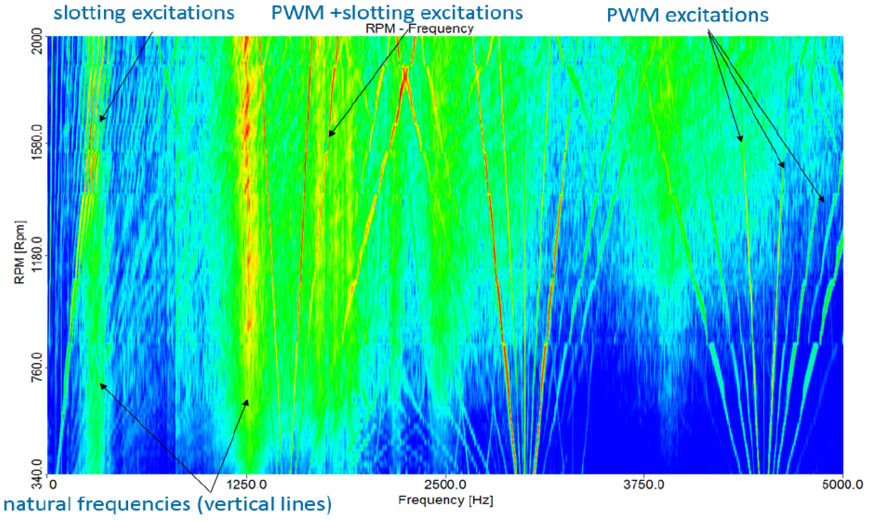
  • y-axis: time, rotational speed, or supply frequency of the machine.
  • x-axis: vibration frequency.
  • z-axis: magnitude of vibration (displacement, velocity, or acceleration), in radial or tangential direction.
In a spectrogram, the magnitude of vibration is shown as a color scale, typically ranging from blue for the lowest value to red for the highest value. Some vertical bands usually appear in spectrograms and indicate the natural frequencies of the machine [13]. An example of these natural frequencies in a spectrogram is shown in Figure 4:

7. Conclusions

This article reviews the current state of the art of noise in electric motors. First, a brief introduction of noise is given, introducing the decibel unit, the audible spectrum, the acoustic pressure and power, and the main noise-related standards.
Then, the sources of electromagnetic noise and vibration in electrical machines, which include aerodynamic, mechanical and electromagnetic factors, are presented. One commonly overlooked factor in electromagnetic considerations is the neglect of the tangential component of electromagnetic force. It is crucial to verify the frequency of this electromagnetic force to prevent it from aligning with the natural frequency of the stator. This analysis is performed with radial and axial flux machine topologies. Additionally, the influence of power supply and winding configuration is assessed, with double layer windings proving more effective than single layer windings.
Different methods to calculate electromagnetic force, natural frequencies and noise are presented such as analytical, numerical and semi-analytical. Two analytical methods for calculating electromagnetic forces have been analyzed, MT and the VWP. Interestingly, both methods obtain very similar results, indicating their reliability.
Many noise reduction techniques for induction motors, PMMs and AFMs are presented such as skewing, stator and rotor notching or slot opening width modification. In the case of the AFM topology, it has been concluded that reducing cogging torque not only leads to a decrease in torque fluctuations, but also contributes to a reduction in noise generation. Finally, noise measurement standards and techniques are presented. The main objective of this work is to provide a complete guide for the design and calculation of low-noise motors.

Author Contributions

Conceptualization, P.G., G.B. and A.J.M.; methodology, P.G., G.B. and A.J.M.; investigation, P.G.; resources, P.G.; writing—original draft preparation, P.G.; writing—review and editing, G.B. and A.J.M.; visualization, P.G.; supervision, G.B. and A.J.M.; funding acquisition, P.G. All authors have read and agreed to the published version of the manuscript.

Funding

This work received financial support from the Basque Government through the Bikaintek program (Grant no. 016-B2/2021).

Data Availability Statement

No new data were created or analyzed in this study. Data sharing is not applicable to this article.

Conflicts of Interest

The authors declare no conflict of interest.

References

  1. Hillhouse, J. Basic sound level knowledge for electric motor application. In Proceedings of the 2010 Record of Conference Papers Industry Applications Society 57th Annual Petroleum and Chemical Industry Conference (PCIC), San Antonio, TX, USA, 20–22 September 2010; pp. 1–8. [Google Scholar]
  2. Gieras, J.; Wang, C.; Lai, J. Noise of Polyphase Electric Motors; Taylor & Francis Group: Boca Ratón, FL, USA, 2005. [Google Scholar]
  3. Lara, F.R.; Jiménez-Romero, R.; Pérez-Hidalgo, F.; Redel-Macías, M.D. Influence of constructive parameters and power signals on sound quality and airborne noise radiated by Inverter-Fed Induction Motors. Measurement 2015, 73, 503–514. [Google Scholar] [CrossRef]
  4. Vijayraghavan, P.; Krishnan, R. Noise in electric machines: A review. IEEE Trans. Ind. Appl. 1999, 35, 1007–1013. [Google Scholar] [CrossRef]
  5. Finley, W. Noise in induction motors--Causes and treatments. IEEE Trans. Ind. Appl. 1990, 27, 55–63. [Google Scholar] [CrossRef]
  6. Tischmacher, H.; Tsoumas, I.; Eichinger, B.; Werner, U. Case studies of acoustic noise emission from inverter-fed asynchronous machines. In Proceedings of the XIX International Conference on Electrical Machines—ICEM 2010, Rome, Italy, 6–8 September 2010; pp. 1–8. [Google Scholar]
  7. Wang, C.; Astfalck, A.; Lai, J. Sound power radiated from an inverter-driven induction motor: Experimental investigation. IEEE Proc.-Electr. Power Appl. 2002, 149, 46–52. [Google Scholar] [CrossRef]
  8. Lo, E.; Chan, C.C.; Zhu, Z.Q.; Xu, L.; Howe, D.; Chau, K.T. Acoustic noise radiated by PWM-controllel induction machine drives. IEEE Trans. Ind. Electron. 2000, 47, 880–889. [Google Scholar] [CrossRef] [Green Version]
  9. Ellison, A.; Yang, S. Effect of rotor eccentricity on acoustic noise from induction motor. Proc. Inst. Electr. Eng. 1971, 118, 174–184. [Google Scholar] [CrossRef]
  10. Kim, D.-J.; Kim, H.j.; Hong, J.P.; Chuljun, P. Estimation of Acoustic Noise and Vibration in an Induction Machine Considering Rotor Eccentricity. IEEE Trans. Magn. 2014, 50, 857–860. [Google Scholar] [CrossRef]
  11. Xu, X.; Han, Q.; Chu, F. Review of Electromagnetic Vibration in Electrical Machines. Energies 2018, 11, 1779. [Google Scholar] [CrossRef] [Green Version]
  12. Amor, A.; Timar, P.L.; Poloujadoff, M. Induction squirrel cage machine design with minimization of electromagnetic noise. IEEE Trans. Energy Convers. 1996, 10, 681–687. [Google Scholar] [CrossRef]
  13. Souron, Q.; Le Besnerais, J.; Hecquet, M. Analysis of electromagnetically-induced vibrations of electrical machines based on spatiogram technique. In Proceedings of the XVII International Symposium on Electromagnetic Fields in Mechatronics, Electrical and Electronic Engineering, Valencia, Spain, 10–12 September 2015; pp. S23–S32. [Google Scholar]
  14. Weilharter, B.; Biro, O.; Rainer, S. Numerical investigation of the 3D vibrational behaviour of skewed induction machines due to rotating force waves. COMPEL Int. J. Comput. Math. Electr. Electron. Eng. 2012, 31, 1503–1512. [Google Scholar] [CrossRef]
  15. Alger, P.L. The Magnetic Noise of Polyphase Induction Motors [includes discussion]. In Transactions of the American Institute of Electrical Engineers. Part III: Power Apparatus and Systems; IEEE: Piscataway, NJ, USA, 1954; Volume 73. [Google Scholar] [CrossRef]
  16. Valavi, M.; Nysveen, A.; Nilssen, R. Characterization of radial magnetic forces in low-speed permanent magnet wind generator with non-overlapping concentrated windings. In Proceedings of the 2012 XXth International Conference on Electrical Machines, Marseille, France, 2–5 September 2012; pp. 2943–2948. [Google Scholar]
  17. Benbouzid, M.; Reyne, G.; Dérou, S.; Foggia, A. Finite element modeling of a synchronous machine: Electromagnetic forces and modes shapes. IEEE Trans. Magn. 1993, 29, 2014–2018. [Google Scholar] [CrossRef]
  18. Valavi, M.; Nysveen, A.; Nilssen, R.; Rolvag, T. Slot Harmonic Effect on Magnetic Forces and Vibration in Low-Speed Permanent-Magnet Machine With Concentrated Windings. IEEE Trans. Ind. Appl. 2014, 50, 3304–3313. [Google Scholar] [CrossRef]
  19. Le Besnerais, J. Vibro-Acoustic Analysis of Radial and Tangential Airgap Magnetic Forces in Permanent Magnet Synchronous Machines. IEEE Trans. Magn. 2014, 51, 8105609. [Google Scholar] [CrossRef]
  20. Lan, H.; Zou, J.; Xu, Y.; Zhao, B. Analysis of Global and Local Force Harmonics and Their Effects on Vibration in Permanent Magnet Synchronous Machines. IEEE Trans. Energy Convers. 2017, 32, 1523–1532. [Google Scholar] [CrossRef]
  21. Ellison, A.J.; Moore, C.J. Acoustic noise and vibration of rotating electric machines. Proc. Inst. Electr. Eng. 1968, 115, 1633–1640. [Google Scholar] [CrossRef]
  22. Saito, A.; Suzuki, H.; Kuroishi, M.; Nakai, H. Efficient forced vibration reanalysis method for rotating electric machines. J. Sound Vib. 2015, 334, 388–403. [Google Scholar] [CrossRef]
  23. Devillers, E.; Hecquet, M.; Le Besnerais, J.; Régniez, M. Tangential effects on magnetic vibrations and acoustic noise of induction machines using subdomain method and electromagnetic vibration synthesis. In Proceedings of the 2017 IEEE International Electric Machines and Drives Conference (IEMDC), Miami, FL, USA, 21–24 May 2017; pp. 1–8. [Google Scholar]
  24. Zuo, S.; Lin, F.; Wu, X. Electromagnetic Vibration and Noise Analysis of Permanent Magnet Synchronous Motor with Different Slot-pole Combinations. IET Electr. Power Appl. 2016, 10, 900–908. [Google Scholar] [CrossRef]
  25. Noda, S.; Mori, S.; Ishibashi, F.; Itomi, K. Effect of Coils on Natural Frequencies of Stator Cores in Small Induction Motors. IEEE Trans. Energy Convers. 1987, EC-2, 93–99. [Google Scholar] [CrossRef]
  26. Cristian, D.; Cassoret, B.; Brudny, J.-F.; Belgrand, T. AC Magnetic Circuits Using Nonsegmented Shifted Grain Oriented Electrical Steel Sheets: Impact on Induction Machine Magnetic Noise. IEEE Trans. Magn. 2012, 48, 1409–1412. [Google Scholar] [CrossRef]
  27. Watanabe, S.; Kenjo, S.; Ide, K.; Sato, F.; Yamamoto, M. Natural Frequencies and Vibration Behaviour of Motor Stators. IEEE Trans. Power Appar. Syst. 1983, PAS-102, 949–956. [Google Scholar] [CrossRef]
  28. Cai, W.; Pillay, P.; Tang, Z. Impact of stator windings and end-bells on resonant frequencies and mode shapes of switched reluctance motors. IEEE Trans. Ind. Appl. 2002, 38, 1027–1036. [Google Scholar] [CrossRef] [Green Version]
  29. Le Besnerais, J.; Fasquelle, A.; Hecquet, M.; Lanfranchi, V.; Brochet, P. A Fast Noise-Predictive Multiphysical Model of the PWM-controlled Induction Machine. In Proceedings of the International Conference on Electrical Machines (ICEM’06), Chania, Greece, 2–5 September 2006. [Google Scholar]
  30. Le Besnerais, J. Reduction of Magnetic Noise in PWM-Supplied Induction Machines-Low-Noise Design Rules and Multi-Objective Optimisation. Ph.D. Thesis, Ecole Centrale de Lille, Villeneuve-d’Ascq, France, 2008. [Google Scholar]
  31. Kaku, B.; Miyashita, I.; Sone, S. A novel prediction method of acoustic magnetic noise based on induction motor’s NHCC function. IEEE Trans. Ind. Electron. 1999, 46, 398–406. [Google Scholar] [CrossRef]
  32. Nau, S.L.; Mello, H.G.G. Acoustic noise in induction motors: Causes and solutions. In Proceedings of Record of Conference Papers. Industry Applications Society Forty-Seventh Annual Conference. 2000 Petroleum and Chemical Industry Technical Conference (Cat. No.00CH37112); IEEE: Piscataway, NJ, USA, 2000; pp. 253–263. [Google Scholar]
  33. Zhihuan, S.; Renyuan, T.; Shenbo, Y.; Hongyang, Z. The influence of vibration and acoustic noise of axial flux permanent magnet machines by inverter. In Proceedings of the 2010 International Conference on Mechanic Automation and Control Engineering, Wuhan, China, 26–28 June 2010; pp. 2423–2426. [Google Scholar]
  34. Xu, L.; Zhu, Z.Q.; Howe, D. Acoustic noise radiated from direct torque controlled induction motor drives. IEE Proc. -Electr. Power Appl. 2000, 147, 491–496. [Google Scholar] [CrossRef]
  35. Bouyahi, H.; Ben Smida, K.; Khedher, A. Experimental study of PWM strategy effect on acoustic noise generated by inverter-fed induction machine. Int. Trans. Electr. Energy Syst. 2019, 30, e12249. [Google Scholar] [CrossRef]
  36. Kumar, A.C.B.; Narayanan, G. Variable-Switching Frequency PWM Technique for Induction Motor Drive to Spread Acoustic Noise Spectrum With Reduced Current Ripple. IEEE Trans. Ind. Appl. 2016, 52, 3927–3938. [Google Scholar] [CrossRef]
  37. Singh, G.K. A research survey of induction motor operation with non-sinusoidal supply wave forms. Electr. Power Syst. Res. 2005, 75, 200–213. [Google Scholar] [CrossRef]
  38. Xu, Y.; Yuan, Q.; Zou, J.; Li, Y. Analysis of Triangular Periodic Carrier Frequency Modulation on Reducing Electromagnetic Noise of Permanent Magnet Synchronous Motor. IEEE Trans. Magn. 2012, 48, 4424–4427. [Google Scholar] [CrossRef]
  39. Nistor, C.G.; Plesa, O.I.; Scutaru, G.; Peter, I.; Ionescu, R.M. Numerical modeling of magnetic noise for three phase asynchronous motors through the software Flux 2D. In Proceedings of the 2012 International Conference on Applied and Theoretical Electricity (ICATE), Craiova, Romania, 25–27 October 2012; pp. 1–4. [Google Scholar]
  40. Ionescu, R.M.; Munteanu, A. A comparative study of the winding type influence on the noise level of two-speed three-phase induction motors. In Proceedings of the 2014 International Conference on Optimization of Electrical and Electronic Equipment (OPTIM), Cheile Gradistei, Romania, 22–24 May 2014; pp. 458–465. [Google Scholar]
  41. Güemes, J.; Iraolagoitia, A.; Fernández, P.; Donsión, M. Comparative study of PMSM with integer-slot and fractional-slot windings. In Proceedings of the XIX International Conference on Electrical Machines-ICEM 2010, Rome, Italy, 6–8 September 2010; pp. 1–6. [Google Scholar]
  42. Deng, W.; Zuo, S. Electromagnetic Vibration and Noise of the Permanent Magnet Synchronous Motors for Electric Vehicles: An Overview. IEEE Trans. Transp. Electrif. 2018, 5, 59–70. [Google Scholar] [CrossRef]
  43. Valavi, M.; Nysveen, A.; Nilssen, R. Magnetic forces and vibration in permanent magnet machines with non-overlapping concentrated windings: A review. In Proceedings of the 2012 IEEE International Conference on Industrial Technology, ICIT 2012, Athens, Greece, 19–21 March 2012. [Google Scholar] [CrossRef]
  44. Li, Z.; Di, C.; Bao, X. Analysis of vibration and noise of induction motor equipped with concentric single-double-layer star-delta winding. Chin. J. Electr. Eng. 2019, 5, 36–46. [Google Scholar] [CrossRef]
  45. Devillers, E.; Le Besnerais, J.; Souron, Q.; Hecquet, M. Characterization of acoustic noise and vibrations due to magnetic forces in induction machines for transport applications using MANATEE software. In Proceedings of ISMA; ISMA: Leuven, Belgium, 2016. [Google Scholar]
  46. Le Besnerais, J.; Lanfranchi, V.; Hecquet, M.; Lemaire, G.; Augis, E.; Brochet, P. Characterization and Reduction of Magnetic Noise Due to Saturation in Induction Machines. IEEE Trans. Magn. 2009, 45, 2003–2008. [Google Scholar] [CrossRef]
  47. Delaere, K.; Belmans, R.; Hameyer, K. Influence of rotor slot wedges on stator currents and stator vibration spectrum of induction machines: A transient finite-element analysis. IEEE Trans. Magn. 2003, 39, 1492–1494. [Google Scholar] [CrossRef]
  48. Kron, G. Induction Motor Slot Combinations Rules to Predetermine Crawling, Vibration, Noise and Hooks in the Speed-Torque Curve. Trans. Am. Inst. Electr. Eng. 1931, 50, 757–767. [Google Scholar] [CrossRef]
  49. Cheraghi, M.; Karimi, M.; Booin, M.B. An investigation on acoustic noise emitted by induction motors due to magnetic sources. In Proceedings of the 2018 9th Annual Power Electronics, Drives Systems and Technologies Conference (PEDSTC), Tehran, Iran, 13–15 February 2018; pp. 104–109. [Google Scholar]
  50. Cassoret, B.; Lecointe, J.P.; Brudny, J.F. Influence of the pole number on the magnetic noise of electrical ac machines. Prog. Electromagn. Res. B 2011, 33, 83–97. [Google Scholar] [CrossRef] [Green Version]
  51. Asano, Y.; Honda, Y.; Murakami, H.; Takeda, Y.; Morimoto, S. Novel noise improvement technique for a PMSM with concentrated winding. In Proceedings of the Power Conversion Conference-Osaka 2002 (Cat. No.02TH8579), Osaka, Japan, 2–5 April 2002; Volume 462, pp. 460–465. [Google Scholar]
  52. Islam, M.S.; Islam, R.; Sebastian, T. Noise and Vibration Characteristics of Permanent-Magnet Synchronous Motors Using Electromagnetic and Structural Analyses. IEEE Trans. Ind. Appl. 2014, 50, 3214–3222. [Google Scholar] [CrossRef]
  53. Boesing, M.; De Doncker, R. Exploring a vibration synthesis process for the acoustic characterization of electric drives. IEEE Trans. Ind. Appl. 2012, 48, 70–78. [Google Scholar] [CrossRef]
  54. Verez, G.; Barakat, G.; Amara, Y.; Hoblos, G. Impact of Pole and Slot Combination on Vibrations and Noise of Electromagnetic Origins in Permanent Magnet Synchronous Motors. IEEE Trans. Magn. 2015, 51, 8101104. [Google Scholar] [CrossRef]
  55. Jang, G.H.; Lieu, D.K. The effect of magnet geometry on electric motor vibration. IEEE Trans. Magn. 1991, 27, 5202–5204. [Google Scholar] [CrossRef]
  56. Krotsch, J.; Piepenbreier, B. Radial Forces in External Rotor Permanent Magnet Synchronous Motors With Non-Overlapping Windings. IEEE Trans. Ind. Electron. 2012, 59, 2267–2276. [Google Scholar] [CrossRef]
  57. Hao, Z.; Ma, Y.; Wang, P.; Luo, G.; Chen, Y. A Review of Axial-Flux Permanent-Magnet Motors: Topological Structures, Design, Optimization and Control Techniques. Machines 2022, 10, 1178. [Google Scholar] [CrossRef]
  58. Credo, A.; Tursini, M.; Villani, M.; Di Lodovico, C.; Orlando, M.; Frattari, F. Axial Flux PM In-Wheel Motor for Electric Vehicles: 3D Multiphysics Analysis. Energies 2021, 14, 2107. [Google Scholar] [CrossRef]
  59. Lu, M.H.; Jen, M.U. Acoustic characteristics concerning construction and drive of axial-flux motors for electric bicycles. In Proceedings of the 2013 World Electric Vehicle Symposium and Exhibition (EVS27), Barcelona, Spain, 17–20 November 2013; pp. 1–8. [Google Scholar]
  60. Wang, W.; Wang, H.; Karimi, H. Study on the Characteristics of Electromagnetic Noise of Axial Flux Permanent Magnet Synchronous Motor. Abstr. Appl. Anal. 2014, 2014, 764105. [Google Scholar] [CrossRef] [Green Version]
  61. Deng, W.; Zuo, S.; Lin, F.; Wu, S. Influence of Pole and Slot Combinations on Vibration and Noise in External Rotor Axial Flux in-Wheel Motors. IET Electr. Power Appl. 2017, 11, 586–594. [Google Scholar] [CrossRef]
  62. Slutskiy, D.; Aung, S.H.; Basnet, S. Comparison of Axial and Radial Flux Permanent Magnet Machines. In Proceedings of the 2022 North American Power Symposium (NAPS), Salt Lake City, UT, USA, 9–11 October 2022; pp. 1–6. [Google Scholar]
  63. Haodong, Y.; Chen, Y. Influence of Radial Force Harmonics With Low Mode Number on Electromagnetic Vibration of PMSM. IEEE Trans. Energy Convers. 2014, 29, 38–45. [Google Scholar] [CrossRef]
  64. Lecointe, J.P.; Romary, R.; Brudny, J.F.; Czapla, T. Five methods of stator natural frequency determination: Case of induction and switched reluctance machines. Mech. Syst. Signal Process. 2004, 18, 1133–1159. [Google Scholar] [CrossRef]
  65. Li, Q. A novel analytical method of calculating of stator natural frequency for axial flux permanent magnet machines. In Proceedings of the 2011 International Conference on Electrical Machines and Systems, Beijing, China, 20–23 August 2011; pp. 1–3. [Google Scholar]
  66. Boisson, J.; Louf, F.; Ojeda, J.; Mininger, X.; Gabsi, M. Analytical Approach for Mechanical Resonance Frequencies of High-Speed Machines. IEEE Trans. Ind. Electron. 2014, 61, 3081–3088. [Google Scholar] [CrossRef]
  67. McCloskey, A.; Arrasate, X.; Hernández, X.; Gómez, I.; Almandoz, G. Analytical calculation of vibrations of electromagnetic origin in electrical machines. Mech. Syst. Signal Process. 2018, 98, 557–569. [Google Scholar] [CrossRef]
  68. Xing, Z.; Wang, X.; Zhao, W. An Accurate Calculation Method of Natural Frequencies of the Radial-Flux Slotted Motors Considering End Covers. IEEE Trans. Ind. Electron. 2023, 70, 5516–5526. [Google Scholar] [CrossRef]
  69. Torregrossa, D.; Peyraut, F.; Fahimi, B.; M’Boua, J.; Miraoui, A. Multiphysics Finite-Element Modeling for Vibration and Acoustic Analysis of Permanent Magnet Synchronous Machine. IEEE Trans. Energy Convers. 2011, 26, 490–500. [Google Scholar] [CrossRef]
  70. Deng, W.; Zuo, S. Analytical Modeling of the Electromagnetic Vibration and Noise for an External Rotor Axial Flux in-Wheel Motor. IEEE Trans. Ind. Electron. 2018, 65, 1991–2000. [Google Scholar] [CrossRef]
  71. Pile, R.; Devillers, E.; Le Besnerais, J. Comparison of Main Magnetic Force Computation Methods for Noise and Vibration Assessment in Electrical Machines. IEEE Trans. Magn. 2018, 54, 8104013. [Google Scholar] [CrossRef] [Green Version]
  72. Pile, R.; Le Besnerais, J.; Parent, G.; Devillers, E.; Henneron, T.; Le Menach, Y.; Lecointe, J.-P. Analytical study of air-gap surface force -application to electrical machines. Open Phys. 2020, 18, 658–673. [Google Scholar] [CrossRef]
  73. Le Besnerais, J.; Lanfranchi, V.; Hecquet, M.; Brochet, P. Multiobjective Optimization of Induction Machines Including Mixed Variables and Noise Minimization. IEEE Trans. Magn. 2008, 44, 1102–1105. [Google Scholar] [CrossRef]
  74. Weilharter, B.; Biro, O.; Lang, H.; Ofner, G.; Rainer, S. Validation of a Comprehensive Analytic Noise Computation Method for Induction Machines. IEEE Trans. Ind. Electron. 2012, 59, 2248–2257. [Google Scholar] [CrossRef]
  75. Sathyan, S.; Aydin, U.; Belahcen, A. Acoustic Noise Computation of Electrical Motors Using the Boundary Element Method. Energies 2020, 13, 245. [Google Scholar] [CrossRef] [Green Version]
  76. Zuo, S.; Lin, F.; Wu, X. Noise Analysis, Calculation, and Reduction of External Rotor Permanent-Magnet Synchronous Motor. IEEE Trans. Ind. Electron. 2015, 62, 6204–6212. [Google Scholar] [CrossRef]
  77. Lin, F.; Zuo, S.; Deng, W.; Wu, S. Modeling and Analysis of Electromagnetic Force, Vibration and Noise in Permanent Magnet Synchronous Motor Considering Current Harmonics. IEEE Trans. Ind. Electron. 2016, 63, 7455–7466. [Google Scholar] [CrossRef]
  78. Deng, W.; Zuo, S. Axial Force and Vibroacoustic Analysis of External Rotor Axial Flux Motors. IEEE Trans. Ind. Electron. 2017, 65, 2018–2030. [Google Scholar] [CrossRef]
  79. Park, S.; Kim, W.; Kim, S.-I. A Numerical Prediction Model for Vibration and Noise of Axial Flux Motors. IEEE Trans. Ind. Electron. 2014, 61, 5757–5762. [Google Scholar] [CrossRef]
  80. Wang, C.; Lai, J.; Pulle, D.W.J. Prediction of acoustic noise from variable-speed induction motors: Deterministic versus statistical approaches. IEEE Trans. Ind. Appl. 2002, 38, 1037–1044. [Google Scholar] [CrossRef]
  81. Delaere, K.; Iadevaia, M.; Heylen, W.; Sas, P.; Hameyer, K.; Beimans, R. Statistical energy analysis of acoustic noise and vibration for electric motors: Transmission from air gap field to motor frame. In Proceedings of the Conference Record of the 1999 IEEE Industry Applications Conference. Thirty-Forth IAS Annual Meeting (Cat. No.99CH36370), Phoenix, AZ, USA, 3–7 October 1999; Volume 1893, pp. 1897–1902. [Google Scholar]
  82. Braunisch, D.; Ponick, B.; Bramerdorfer, G. Combined Analytical–Numerical Noise Calculation of Electrical Machines Considering Nonsinusoidal Mode Shapes. IEEE Trans. Magn. 2013, 49, 1407–1415. [Google Scholar] [CrossRef]
  83. Kim, D.-J.; Jung, J.-W.; Hong, J.P.; Kim, K.-J.; Chuljun, P. A Study on the Design Process of Noise Reduction in Induction Motors. IEEE Trans. Magn. 2012, 48, 4638–4641. [Google Scholar] [CrossRef]
  84. Wang, C.; Bao, X.; Xu, S.; Zhou, Y.; Xu, W.; Chen, Y. Analysis of Vibration and Noise for Different Skewed Slot Type Squirrel-Cage Induction Motor. IEEE Trans. Magn. 2017, 53, 8206006. [Google Scholar] [CrossRef]
  85. Besnerais, J.L.; Souron, Q. Design of quiet permanent magnet synchronous electrical motors by optimum skew angle. In Proceedings of the ICSV Conference, Athens, Greece, 10–14 July 2016. [Google Scholar]
  86. Lin, F.; Zuo, S.-G.; Deng, W.-Z.; Wu, S.-L. Reduction of vibration and acoustic noise in permanent magnet synchronous motor by optimizing magnetic forces. J. Sound Vib. 2018, 429, 193–205. [Google Scholar] [CrossRef]
  87. Wang, S.; Hong, J.; Sun, Y.; Cao, H. Effect Comparison of Zigzag Skew PM Pole and Straight Skew Slot for Vibration Mitigation of PM Brush DC Motors. IEEE Trans. Ind. Electron. 2019, 67, 4752–4761. [Google Scholar] [CrossRef]
  88. Dong, Q.; Liu, X.; Qi, H.; Sun, C.; Wang, Y. Analysis and evaluation of electromagnetic vibration and noise in permanent magnet synchronous motor with rotor step skewing. Sci. China Technol. Sci. 2019, 62, 839–848. [Google Scholar] [CrossRef]
  89. Zhou, G.; Shen, J. Rotor Notching for Electromagnetic Noise Reduction of Induction Motors. IEEE Trans. Ind. Appl. 2017, 53, 3361–3370. [Google Scholar] [CrossRef]
  90. Lan, H.; Chen, Q.; Zou, J.; Xu, Y.; Wang, M.; Liu, M. Influence of dummy slots on noise and vibration performance in permanent magnet synchronous machines. In Proceedings of the 2017 IEEE Transportation Electrification Conference and Expo, Asia-Pacific (ITEC Asia-Pacific), Harbin, China, 7–10 August 2017; pp. 1–6. [Google Scholar]
  91. Lan, H.; Zou, J.; Xu, Y.; Wang, M.; Yan, L. Characterization and Reduction of Zeroth Spatial-Order Radial Force in Permanent Magnet Synchronous Machines. In IET Conference Proceedings; Institution of Engineering and Technology: Guiyang, China, 2018; pp. 72–78. [Google Scholar] [CrossRef]
  92. Xing, Z.; Wang, X.; Zhao, W. Research on weakening measure of radial electromagnetic force waves in permanent magnet synchronous motors by inserting auxiliary slots. IET Electr. Power Appl. 2020, 14, 1381–1395. [Google Scholar] [CrossRef]
  93. Khan, M.A.; Khan, F.; Rahman, L.U.; Fatima, A. Analysis and Electromagnetic Noise suppression of three-phase Squirrel Cage Induction Motor. In Proceedings of the 2018 International Conference on Computing, Electronic and Electrical Engineering (ICE Cube), Quetta, Pakistan, 12–13 November 2018; pp. 1–5. [Google Scholar]
  94. Ye, F.; Liu, W. Analysis and Optimization of Electromagnetic Noise of Interior Permanent Magnet Synchronous Motor for Vehicle. IOP Conf. Ser. Mater. Sci. Eng. 2020, 768, 062009. [Google Scholar] [CrossRef]
  95. Wang, Y.; Gao, H.; Wang, H.; Ma, W. NVH Optimization Analysis of Permanent Magnet Synchronous Motor by Rotor Slotting. Vehicles 2020, 2, 287–303. [Google Scholar] [CrossRef]
  96. Putri, A.; Rick, S.; Franck, D.; Hameyer, K. Application of Sinusoidal Field Pole in a Permanent-Magnet Synchronous Machine to Improve the NVH Behavior Considering the MTPA and MTPV Operation Area. IEEE Trans. Ind. Appl. 2016, 52, 2280–2288. [Google Scholar] [CrossRef]
  97. Le Besnerais, J.; Lanfranchi, V.; Hecquet, M.; Romary, R.; Brochet, P. Optimal Slot Opening Width for Magnetic Noise Reduction in Induction Motors. IEEE Trans. Energy Convers. 2010, 24, 869–874. [Google Scholar] [CrossRef]
  98. Jung, J.-W.; Lee, S.-H.; Lee, G.-H.; Hong, J.P.; Lee, D.-H.; Kim, K.-N. Reduction Design of Vibration and Noise in IPMSM Type Integrated Starter and Generator for HEV. IEEE Trans. Magn. 2010, 46, 2454–2457. [Google Scholar] [CrossRef]
  99. Wang, S.; Li, H. Reduction of Electromagnetic Vibration and Noise in Permanent Magnet Motor for EVs by Optimizing Design of Rotor Based on GPR-PSO Model. J. Electr. Eng. Technol. 2020, 15, 1231–1243. [Google Scholar] [CrossRef]
  100. Besnerais, J.L.; Souron, Q. Effect of magnetic wedges on electromagnetically-induced acoustic noise and vibrations of electrical machines. In Proceedings of the 2016 XXII International Conference on Electrical Machines (ICEM), Lausanne, Switzerland, 4–7 September 2016; pp. 2217–2222. [Google Scholar]
  101. Bauw, G.; Balavoine, F.; Cassoret, B.; Ninet, O.; Romary, R. Damper winding for noise and vibration reduction of PWM-fed induction machines. In Proceedings of the 2017 IEEE International Electric Machines and Drives Conference (IEMDC), Miami, FL, USA, 21–24 May 2017; pp. 1–6. [Google Scholar]
  102. Besnerais, J.L.; Brando, G.; Dannier, A.; Pizzo, A.D.; Noia, L.P.D.; Rizzo, R.; Castellini, L.; Andrea, M.D. Analysis of noise reduction in a low speed and high torque PMSM with tooth concentrated windings. In Proceedings of the 2016 Eleventh International Conference on Ecological Vehicles and Renewable Energies (EVER), Monte Carlo, Monaco, 6–8 April 2016; pp. 1–6. [Google Scholar]
  103. Devillers, E.; Hecquet, M.; Le Besnerais, J.; Lecointe, J.-P. Effect of the load angle on radial and tangential magnetic forces in Permanent Magnet Synchronous Machines. In Proceedings of the ISEF, 2017, Lodz, Poland, 14–16 September 2017. [Google Scholar]
  104. Ni, S.; Bauw, G.; Romary, R.; Cassoret, B.; Le Besnerais, J. Damper Winding for Noise and Vibration Reduction of a Permanent Magnet Synchronous Machine. Sensors 2022, 22, 2738. [Google Scholar] [CrossRef] [PubMed]
  105. Lee, S.H.; Hong, J.P. A Study on the Acoustic Noise Reduction of Interior Permanent Magnet Motor with Concentrated Winding. In Proceedings of the 2008 IEEE Industry Applications Society Annual Meeting, Edmonton, AB, Canada, 5–9 October 2008; pp. 1–5. [Google Scholar]
  106. Deng, W.; Zuo, S. Noise Reduction of Axial-Flux Motors by Combining Various Pole-Arc Coefficients and Circumferential Shifting of Permanent Magnets: An Analytical Approach. IET Electr. Power Appl. 2019, 13, 951–957. [Google Scholar] [CrossRef]
  107. Wang, X.; Zhang, Y.; Li, N. Analysis and Reduction of Electromagnetic Noise of Yokeless and Segmented Armature Axial Flux Motor. In Proceedings of the 2022 25th International Conference on Electrical Machines and Systems (ICEMS), Chiang Mai, Thailand, 29 November–2 December 2022; pp. 1–6. [Google Scholar]
  108. Letelier, A.; Gonzalez, D.; Tapia, J.; Wallace, R.R.; Valenzuela, M. Cogging Torque Reduction in an Axial Flux PM Machine via Stator Slot Displacement and Skewing. IEEE Trans. Ind. Appl. 2007, 43, 685–693. [Google Scholar] [CrossRef]
  109. Baig, M.; Ikram, J.; Iftikhar, A.; Bukhari, S.S.H.; Khan, N.; Ro, J.-S. Minimization of Cogging Torque in Axial Field Flux Switching Machine Using Arc Shaped Triangular Magnets. IEEE Access 2020, 8, 227193–227201. [Google Scholar] [CrossRef]
  110. Gulec, M.; Aydin, M. Magnet asymmetry in reduction of cogging torque for integer slot axial flux permanent magnet motors. IET Electr. Power Appl. 2014, 8, 189–198. [Google Scholar] [CrossRef]
  111. Kumar, P.; Srivastava, R. Cost-effective stator modification techniques for cogging torque reduction in axial flux permanent magnet machines. In Proceedings of the 2018 IEEE Transportation Electrification Conference and Expo, Asia-Pacific (ITEC Asia-Pacific), Bangkok, Thailand, 6–9 June 2018; pp. 1–5. [Google Scholar]
  112. Wanjiku, J.; Khan, M.; Barendse, P.; Pillay, P. Influence of Slot-Openings and Tooth Profile on Cogging Torque in Axial-Flux PM Machines. IEEE Trans. Ind. Electron. 2015, 62, 7578–7589. [Google Scholar] [CrossRef]
  113. Dzhankhotov, V.; Pyrhönen, J. Passive LC Filter Design Considerations for Motor Applications. IEEE Trans. Ind. Electron. 2013, 60, 4253–4259. [Google Scholar] [CrossRef]
  114. Cassoret, B.; Corton, R.; Roger, D.; Brudny, J.F. Magnetic noise reduction of induction machines. IEEE Trans. Power Electron. 2003, 18, 570–579. [Google Scholar] [CrossRef]
  115. Girgin, M.T.; Aydin, M. Elimination of Cogging Torque for Axial Flux Permanent Magnet Motors Based on Current Harmonic Injection. In Proceedings of the 2020 International Conference on Electrical Machines (ICEM), Gothenburg, Sweden, 23–26 August 2020; pp. 1117–1122. [Google Scholar]
  116. Marignetti, F.; Rubino, G.; Boukadida, Y.; Conti, P.; Gregorio, F.D.; Iengo, E.; Longobardi, V.G. Noise and vibration analysis of an inverter-fed three-phase induction motor. In Proceedings of the 2020 International Symposium on Power Electronics, Electrical Drives, Automation and Motion (SPEEDAM), Sorrento, Italy, 24–26 June 2020; pp. 157–161. [Google Scholar]
  117. Le Besnerais, J.; Lanfranchi, V.; Hecquet, M.; Brochet, P. Characterization and Reduction of Audible Magnetic Noise Due to PWM Supply in Induction Machines. IEEE Trans. Ind. Electron. 2010, 57, 1288–1295. [Google Scholar] [CrossRef]
Figure 1. Main mechanical sources of air gap eccentricity: (a) shape deviation, (b) parallel eccentricity, (c) inclined eccentricity and (d) curved eccentricity [11].
Energies 16 05311 g001
Figure 2. Deformation caused by the spatial distribution of forces [2].
Energies 16 05311 g002
Figure 3. Distribution of normal electromagnetic forces for zero (a), first (b), second (c) and third harmonic (d), where solid dots stand for outwards direction and + stand for inwards direction [60].
Energies 16 05311 g003
Figure 4. Electric motor spectrogram [13].
Energies 16 05311 g004
Table 1. Full band center and cutoff frequencies (adapted from [1]).
Central Frequency [Hz]Cutoff Frequency [Hz]
22
31.5
45
63
88
125
177
250
354
500
707
1000
1414
2000
2828
4000
5657
8000
11,314
Table 2. Summary of some of the most relevant references that calculate natural frequencies.
Calculation MethodReferenceTest ResultsRemarks
Analytical[64]YesResults comparison between 5 different calculation methods, 2 of them analytical
[65]YesAFM natural frequency calculation
[66]YesTwo methods: Stator density modification and addition of mass points
[67]NoAdds equivalent material properties to stator teeth and winding combination
Validation with FEM
[68]YesEnd covers are taken into account
FEM[69]YesComparison between only the stator and the stator, cooling system and housing
[68]YesStator and winding taken into account for the FEM calculation
Table 3. Summary of noise reduction methods and machine type.
MethodReferenceMachine Type
Skew[83,84]Induction
[85,86,87]SPM
[88]IPM
Stator notching[89]Induction
[90,91,92]SPM
Rotor notching[89,93]Induction
[94,95,96]IPM
Slot opening width[97]Induction
[76]SPM
Magnet shape[56,86]SPM
Flux barrier[98,99]IPM
Disclaimer/Publisher’s Note: The statements, opinions and data contained in all publications are solely those of the individual author(s) and contributor(s) and not of MDPI and/or the editor(s). MDPI and/or the editor(s) disclaim responsibility for any injury to people or property resulting from any ideas, methods, instructions or products referred to in the content.

