
Status of Foam as a Liquid Blocking Agent in Porous Media: A Review

NORCE Norwegian Research Centre, Nygårdsgaten 112, 5008 Bergen, Norway
Energies 2023, 16(13), 5063; https://doi.org/10.3390/en16135063
Submission received: 14 March 2023
/
Revised: 10 May 2023
/
Accepted: 14 June 2023
/
Published: 29 June 2023
(This article belongs to the Topic Energy Saving and Energy Efficiency Technologies)
Abstract
:This article summarizes the state-of-the-art knowledge gained from field observations and laboratory studies regarding foam as a liquid controlling agent in porous media. Being the least explored property of foam, its effect and potential have often been overlooked or simply ignored. The aim with this review is therefore to demonstrate the abilities that foam could have to block, reduce, delay, suppress, or divert water flow in porous media. As a liquid controlling agent in porous media, foam has potential for industrial processes that involve fluid injections or fluid withdrawals in porous geological formations, such as improved/enhanced oil recovery (IOR/EOR), matrix-stimulation treatments, underground storage of CO2, hydrogen, compressed-air or natural gas withdrawal, geothermal energy, and contaminated soil-groundwater remediation processes with unwanted aquifer impacts. Improving the water utilization factor and water management in these applications might result in tremendous energic, economic, and environmental incentives that are worth pursuing. Specific focus in this review is given to the post-foam water injection, which determines the ultimate stability and water-blocking capabilities of the foam treatment. Main parameters and mechanisms that can influence foam stability against water injection/intrusion after generation and placement are assessed and discussed. Unresolved issues are highlighted, which give recommendations for further research and field-scale operations.
1. Challenges and Opportunities
Case 1—Unfavorable water injection: In many oilfield operations, water injection is necessary for pressure support and as drive mechanism to recover the oil in place. After water breaks through in the production wells, most oilfields come to a situation of lower well productivity (i.e., low oil recovery per barrel of water injected) and increased water production. An average of 10 barrels of water produced for each barrel of oil extracted from the ground is not unrealistic in many mature oilfields nowadays. Injection and production of water are also very energy-demanding processes which significantly contribute to emissions of greenhouse gases as long as the water handling is managed by gas turbines and compressors that are running on fossil fuels [1,2]. Improved tail-production from mature oil fields is therefore an increasingly important dilemma to decide upon in the ongoing energy debate, as several fields are rapidly approaching a situation where the energy return of producing oil is closing in on the energy invested in drilling new wells, pumping fluids, and handling and circulation of the fluids injected and produced [2,3,4,5,6].
Farajzadeh et al. [1] estimated that at water ratios greater than 90%, more than 70% of the total invested energy is spent on injection- and lift-pumps associated with water injection and its circulation. Clearly, there are tremendous energic, economic, and environmental incentives to improve the water utilization factor, during both the injection and production of water in mature oilfield operations, especially if this can be accomplished without sacrificing hydrocarbon production.
The fundamental causes for low productivity during continued water injection in mature oilfields can be traced to the unfavorable mobility of water relative to the oil in place and geological heterogeneity [7]. The unfavorable mobility of water stems from the lower water viscosity (typically between ~0.2 and 0.6 cP under reservoir conditions) compared with the oil viscosity in place (which has viscosities generally ranging from several to tens of centipoises). The unfavorable viscosity ratio between the oil and water phase leads to adverse mobility ratios that cause the viscous fingering phenomenon and local bypassing of oil [8,9]. The main challenge for oil recovery in field operations, however, is enabling the injected water (or gas) to contact the oil volume in place. Historically, petroleum engineers have tended to underestimate the fluid-flow capacity of the main flow paths within the reservoir, such as fractures, high-permeability layers, and contrasts, which causes conformance problems (i.e., non-uniform displacement fronts, channeling, gravity segregation) that inhibit the injected fluids from contacting significant portions of the reservoir. For water (or gas) injections at the field scale, therefore, early well breakthroughs, rising water/gas cut levels, and reduced tail production are mostly dominated by conformance problems caused by geological heterogeneities [7].
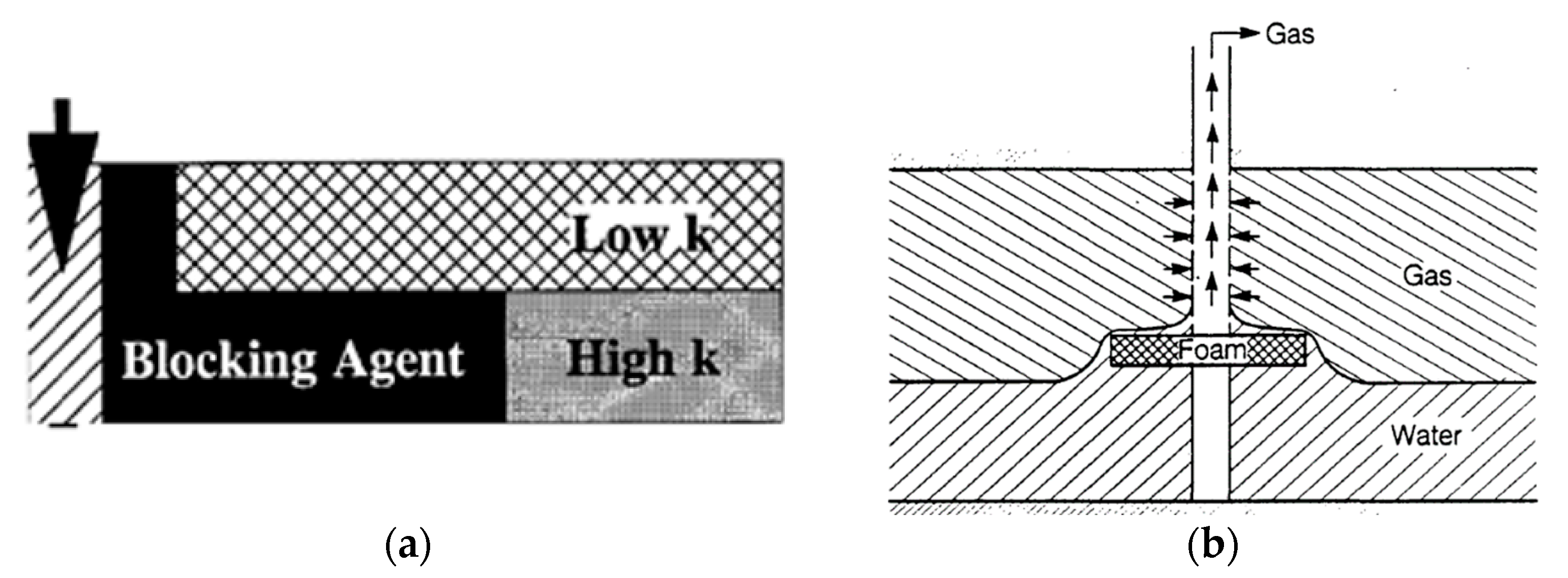
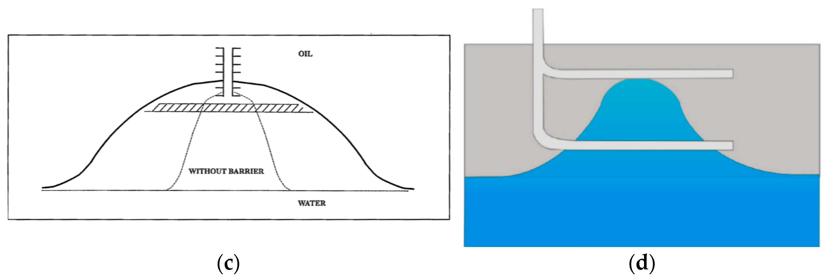
Case 2—Unwanted water production: Unwanted water production can also occur if the reservoir has a water zone beneath the oil- or gas-bearing formation that infiltrates the perforation zone in the near-wellbore area. Water from that zone could then be drawn into the production wells if the pressure drop in the near-wellbore area is too high. This production (rate/pressure) issue is often referred to as water coning [10]. In the classical case of a homogeneous oil zone underlain by a bottom water-zone, the water-oil interface would rise in a shape approximating a cone (Figure 1b–d). Strong water coning will compromise the retrieval of oil and/or gas (e.g., H2, CH4, air) from underground storage, potentially leading to high water-to-oil/gas-to-oil/water-to-gas ratios (WOR/GOR/WGR) and potentially increased production management costs. In such a situation, it would be desirable to reduce or eliminate the coning and production of water to avoid rate reduction in oil and gas production and delay permanent well shut-ins [10,11].
Case 3—Unwanted brine backflow: A third application where water control in porous media might be beneficial is related to CO2 sequestration projects, where cyclic injection schemes of CO2 can be reasonably assumed (e.g., ship injection cannot be continuous, varying CO2 production and availability over time, stops due to planned maintenance/workover, stops due to injection issues/rapidly rising injection pressure). An issue of cyclic CO2 injection is the potential restoration of near-wellbore water saturation by flowback of brine during the shut-in periods, which may exacerbate near-wellbore effects (e.g., geochemical interactions, salt precipitation, hydrate formation) to further impair injectivity in the next phases [12,13,14].
Water blocking agents: Different types of methods, devices, and processes have been proposed and utilized over the many decades of oil and gas production for resolving issues of low well productivity and/or unwanted high water production from water-drive reservoirs, such as (i) drilling of horizontal wells or more targeted well trajectories, including the use of different mechanical barriers downhole [15,16,17]; (ii) pump developments and optimizations, including shifts to renewable-powered water injection (i.e., electrification) from hydropower or floating wind farms [4,18,19]; and (iii) chemical water-blocking/mobility control techniques, which can be applied directly into already existing injection or production wells to combat conformance problems and delay/reduce water production from the wells [7,20,21,22]. While the first (i) alternatives have traditionally been the technologies of choice in the oil industry, and the second (ii) alternatives have been reappearing more frequently because of the increasing focus on energy throughput and CO2 footprint reductions, much less attention has been given to the experiences and lessons-learned during the many decades of applying and developing (iii) in situ water-blocking/mobility control agents that improve the mobility ratio and conformance of the flood.
A distinct property of water-blocking agents is their maximization of penetration and blocking action in the higher-permeability watered-out zones and minimization of damage to the oil-bearing zones. If the main water flow paths can be effectively and selectively blocked-off, subsequent water injections can be diverted into other portions of the reservoir and/or the water production from withdrawal wells can be suppressed (Figure 1a–d).
Several cost-effective liquid-blocking agents for applications in porous media are available (e.g., polymers, gels, foams, emulsions, resins, particles, cements, microorganisms, biofilms, shape-memory materials, hybrid-systems, etc.,). Each agent has distinct advantages and limitations that must be considered for each specific application and reservoir situation [7,21,23,24,25,26,27,28]. Hence, the implementation of these methods requires specific knowledge and understanding of the system properties and feasibility in porous media under reservoir conditions. Encouraging laboratory and simulation results together with techno-economic-risk evaluations could lead to a decision on further field testing and implementations. A successful conformance control application in water-drive reservoirs can contribute to improving the water sweep efficiency, accelerating and increasing oil recovery, and delaying water production compared to a base case or other means of processing, which indirectly reduces the costs associated with drilling new wells; water-lifting, handling, recycling, and disposal; and/or environmental impacts.
Foam in porous media: A technically proven solution to reducing the permeability of the porous media to both gas and water flow simultaneously is to utilize foam [29,30,31]. Foam in porous media is a dispersion of gas in liquid, where the gas phase is made discontinuous due to the formation of thin liquid films (i.e., lamellae) [32,33]. Conceptually, foam generation and foam penetration in porous media should take place in the higher permeability zones where the flow-capacity of fluids is dominant [34,35]. By strategically placing a foam in the high permeability zone for water-diversion, or near the gas-water/oil-water contact to suppress inflow of water, foam can potentially reduce or delay all sources of the conformance problems recently addressed (Figure 1). See also schematic illustration of the foam injection process for groundwater flow diversion in Davarzani et al. [36].
For water-conformance applications, the placed foam should be capable of substantially restricting water flow and should not collapse easily or readily be washed away. In oil-field applications, the foam should selectively block the migration of water and gas but not oil in the reservoir. As such, foam must be able to generate and maintain its stability in the presence of residual oil present in the water producing zones. To determine the potential of foams for water blocking, parameters that affect foam stability and persistence after foam generation and placement therefore need to be thoroughly investigated and understood.
While many/most foam research studies have focused on understanding the dynamics of foam generation, stability, and flow in porous media [24,35,37,38,39,40], surprisingly few include further evaluations of the post-foam stability and persistence of the generated foam through subsequent fluid injections after placement. Considering that foam is thermodynamically unstable, the benefits from such a treatment will only be temporary. Therefore, foam stability after placement is crucial to evaluate in all intended foam applications, as it may jeopardize the success of the foam application.
Figure 1.
Design concepts of foam as a liquid blocking agent in porous media. (a) Idealized blocking agent in a layered reservoir, from Seright [21]. (b) Schematic use of a horizontal foam lens in production wells to reduce water coning, from Persoff et al. [20]. (c) Illustration of a horizontal foam barrier to restrict bottom water coning/cresting, from Singhal [10]. (d) Schematic of the development of bottom water rise in bilateral horizontal well design, from Yong-Ge et al. [22].


A short lifetime of the foam after placement could require the foam process to be repeated more frequently than expected to maintain its purpose. Likewise, foams that cause injectivity problems and/or have been formed in a location where they interfere with gas injection or withdrawal should be evaluated for their abilities to break if needed. A persistent foam (compared to a more mobile foam) should not be easily washed away from the treated zone but remain stagnant as a liquid-suppresser or diverter for extended periods of time. A stagnant foam will also reduce the risks of extensive re- and back-production of the foaming chemicals, which will minimize unnecessary water handling, treatment, and disposal costs.
Since review articles on foam as a liquid controlling agent in porous media, to our knowledge, have not been made before, we find it useful to present an overview of the present knowledge and state of the art. The aim of this study is to summarize the documented observations of foam water-blocking abilities from previous field experiences and laboratory studies to better indicate its advantages, challenges, and possibilities for future applications. In addition, we try to clarify the governing (physical and chemical) parameters and mechanisms determining the foam water-blocking performance, including emphasis on recommended focus-areas for future research and technology development in this area.
2. Foam Properties in Porous Media
A successful foam treatment (in general) requires specific foam properties depending on the problem being combatted. Examples could be strong and stagnant foams (i.e., very low mobility foams) for production well treatments to reduce unwanted high WOR/GOR/WGR. Relatively weaker and more mobile foams can be more optimal to support the injection front with mobility control deeper in the porous formation without impairing injectivity. Accordingly, a sound understanding of the problem to be solved, reservoir properties, and foam properties in porous media becomes important, and thus, a prerequisite for effective foam water mobility control.
The foam performance offered by a given surfactant may depend on several factors, such as surfactant type and concentration [41,42,43,44,45,46], gas composition [47,48,49,50], brine salinity [51,52], rock petrophysical properties and lithology [37,38,39,53], wettability [54,55], foam-oil interactions [45,46,56,57,58,59], temperature and pressure conditions [45,47,48,49], flow rates and foam quality [60,61,62,63], injection strategies, and so forth. Consequently, prior to a field application, it is crucial to evaluate foam properties in representative field material under realistic process conditions.
2.1. Foam Generation, Propagation, and Stability
The efficiency of foam in reducing gas/water mobility (i.e., foam generation), the injection pressure/time required for foam to reach a given depth in the reservoir (i.e., foam propagation), and foam lifetime and persistence in various conditions during, as well as after, its placement (i.e., foam stability) are key questions for all intended field applications of foam.
Typical injection/generation strategies of foam in laboratory studies, as well as field applications, include simultaneously injecting gas and surfactant solution (known as co-injection) [47,49,64] or alternately injecting slugs of surfactant solution and gas (known as SAG) [23,48,65,66]. With the above two injection/generation strategies, foam can be formed in the reservoir by different in situ generation mechanisms [34,67,68,69]. For field applications with relatively insignificant injectivity constraints, foam can also be considered pre-generated topside or downhole before pumped into the reservoir [70]. In laboratory experiments, pre-generated foam is normally formed using filters, core-plugs, or other foam-generator devices placed in front of the studied porous media.
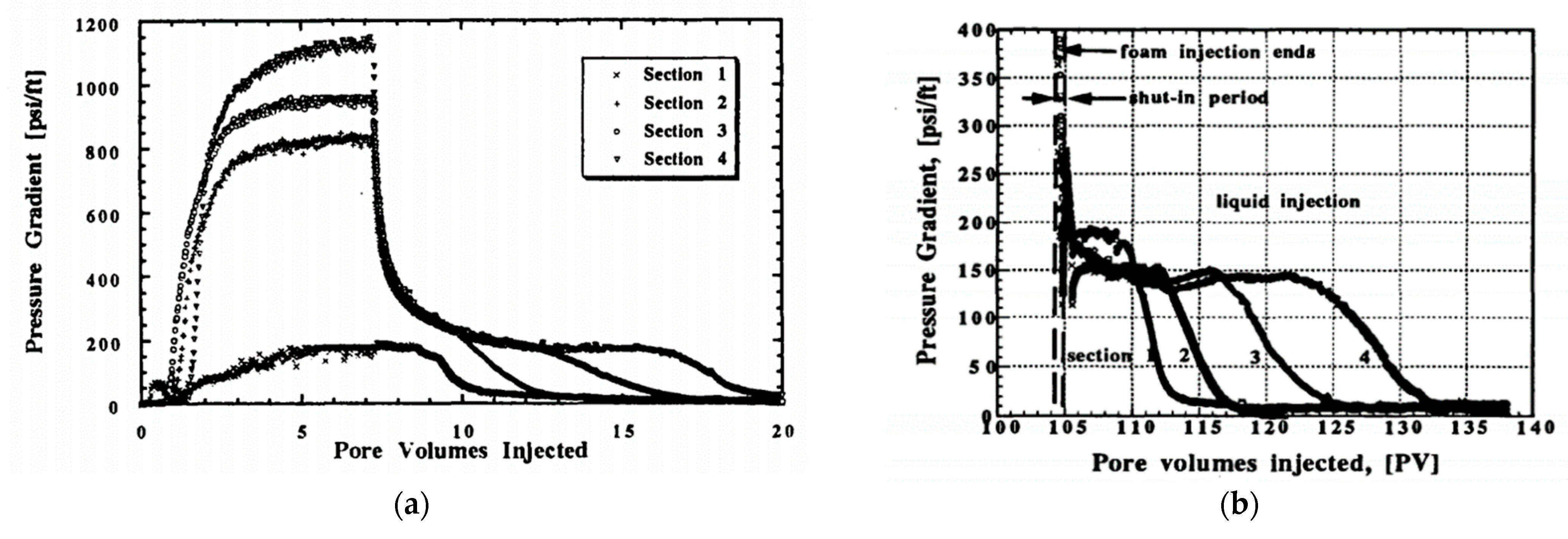
Typical indications of foam generation in the porous medium are attributed to an increase in the injection pressure and a corresponding increase in the differential pressure along the rock sample or in the formation. An example of the characteristic pressure build-up profile (at least in laboratory experiments) of a low-mobility foam state (i.e., strong foam generation) during continuous injection, where the rock sample or near-well reservoir zone has been initially saturated with surfactant solution, can be seen in Figure 2a, which depicts between zero and eight pore volumes being injected. The characteristic pressure build-up profile of a strong foam usually reflects a sharp transient pressure build-up period followed by a plateau in the pressure drop after the injection of a few pore volumes. The transient pressure-build up period is attributed to a substantial reduction in liquid saturation, more stabilized fluid front movement, and significantly delayed fluid breakthroughs when compared with the absence of surfactant. Absence of the transient period indicates a high-mobility coarse or no-foam state with little to no change in the fluid’s mobilities in situ [42,44,47,48,49,61,64,71].
The governing phenomenon behind the plateau in pressure drop and foam strength in general is thought to be related to foam coalescence in porous media due to the capillary pressure (Pc), introduced generally as a critical value, Pc* [76]. At the plateau, the foam system regulates itself around steady-state conditions to maintain Pc close to Pc*. The critical capillary pressure of foam flow in porous media is a function of the used foam formulation (e.g., gas composition, surfactant type, and concentration), water saturation, and rock properties (e.g., absolute permeability, pore attributes). Most theories of foam strength, foam trapping, and foam mobility control in porous media support the concept of a limiting capillary pressure; however, more experimental evidence of its controlling parameters is needed [35,37,38,39,77].
2.2. Choice of Foam Stabilizing Agent
A critical component for all foam applications is the selection of the stabilizing agent. Many candidates are usually available from different vendors. However, specific foam properties and agent requirements are often needed depending on the problem to be solved under the intended reservoir/process conditions, which may severely limit the number of surfactant candidates. Specific surfactant requirements normally include thermal and chemical stability, salt tolerance/solubility, oil/additive compatibility, adsorption, cost, logistics, and environmental criteria. Examples of common surfactant types/names and their performances in laboratory foam studies can be found in the relevant literature and the references therein [24,41,43,46,49,78].
The past decade has seen several studies attempting to improve and strengthen foam properties with varying degrees of success, including advances in surfactant formulas [79], the addition of polymer to the foaming solution [52,80], and the use of nanoparticles [81,82,83,84]. A few studies on surfactant-stabilized N2/CO2-foams, which replacing part of the CO2 content with N2 to overcome the CO2-foam instabilities, have also shown potential [49,79,85].
3. Reasons for Reduced Liquid Phase Mobility in the Porous Media in Presence of Foam
The liquid phase mobility (λw) in porous media is defined as the quotient of the liquid phase effective permeability according to its viscosity, as shown in Equation (1):
where K is the specific permeability (a property of the porous media), krw is the liquid phase relative permeability (a function of the saturation of the fluid), and µw its viscosity (a fluid property). The basic meaning of “water blocking” therefore refers to techniques that can reduce the liquid phase mobility by changing the liquid phase effective permeability and/or viscosity so that λw is reduced.
3.1. Without Surfactant/Foam
Decreased liquid phase relative permeability (krw) in porous media can be accomplished with the injection of gas itself. During gas injections, the resulting increase in the local gas saturation reduces the water saturation (Sw), thereby decreasing the effective liquid permeability. However, the gas phase alone will fail to create a permanent blockage to the liquid flow. During subsequent water injection (in the absence of surfactant/foam), krw will increase until trapped gas saturation (Sgt) has developed. The increase in krw depends on the magnitude of Sgt and the aqueous phase relative permeability curve of the flooded zone [86,87].
3.2. With Surfactant/Foam
Reduction in the liquid phase mobility by foam in porous media conceals the interplay of two distinct but intimately related effects. Namely, foam reduces permeability in porous media to both gas and liquid phases simultaneously. The term “foam mobility control”, which is frequently used in the literature, is therefore a shorthand for describing both the gas and water mobility reductions that can occur in porous media in the presence of foam.
Bernard et al. [29] showed that foam creates a higher trapped-gas saturation (compared to cases without surfactant/foam), which indirectly yields a lower relative permeability to water. A similar general viewpoint on the water phase mobility in the presence of foam has also been reported by several others, stating that during foam generation and foam flow in porous media, foam does not alter the water relative permeability function krw(Sw) but changes it indirectly by increasing the local gas saturation due to the presence of foam [11,29,35,63,71,86,88,89]. Indeed, a common assumption of the current foam models is that the water relative permeability function remains unchanged in the presence of foam. For this statement to be true, the mobility of water in the presence of foam should be considered a continuous phase of constant viscosity throughout the porous media. Hence, the water mobility reduction by foam in porous media can simply be reflected by the lowering of its relative permeability.
The major effect of foam drainage during generation and flow/propagation in porous media is therefore to reduce the value of Sw in the region with dominating water flow capacity and to keep the Sw reduced over an extended period. This will indirectly lead to strong and long-lasting reductions in krw, which directly will suppress the water flow capacity in the higher-permeability layers and distribute/divert it to the less permeable layers. Many foam-flow experiments in the literature show that the water saturation in a foam filled core is often just a few units above connate saturation, and the relative permeability to water (kw) is quite low, typically about 10−2–10−3.
More recently, Eftekhari and Farajzadeh [88] investigated the validity of the assumption that foam in porous media does not impact the liquid-phase mobility. They concluded that the effect of foam on liquid-phase mobility was not pronounced and should be ignored. It was argued that the water relative permeability curves in the absence of surfactant could be used with more confidence only if the capillary pressure was matched to that reached during the foam floods (i.e., in the limit of viscous-dominated flow or high capillary numbers). For that, accurate measurements of water relative permeability for higher capillary numbers than normally obtained without surfactant are thus required.
Still, controversies exist about the dominating flow dynamics of the liquid-phase injected in the presence of foam (i.e., whether the flow of post-foam liquid occurs in the continuous network of the generated lamellae, in the wetting water-films along the rock surfaces, as two separate phases, as fingers through the foam, in channels that are not blocked by foam, or restricted to the smallest water-wet pores which do not contain gas or foam [30,34,38,69,71,75,90,91,92,93,94]. The liquid flow dynamics in the presence of foam may be scale and geometry dependent, but any general recommendations on this matter have not been given so far. Without exact information about the shape and endpoint of the aqueous phase relative permeability in the foamed zone and/or its vicinity with time, estimation of foam-model parameters for predicting the extent of foam mobility control, fluid sweep improvements, and ultimate foam stability in porous formations can be subjected to major errors.
4. Observations Regarding Foam as a Liquid Blocking Agent in Porous Media
4.1. Evidence from the Field
As a water controlling agent, foam has the potential for applications in industrial processes that involve fluid injections or fluid withdrawals in porous subsurface formations, such as improved/enhanced oil recovery (IOR/EOR) [95,96], matrix-acidization treatments [97,98,99], underground storage of gas with strong aquifer impacts [11,20], geothermal energy [100], and contaminated soil-groundwater remediation processes [101,102,103].
During the first twenty years of its use in petroleum engineering (i.e., 1960–1980), foam was proposed as a blocking agent for liquids in porous media (particularly in patents), but most investigators believed that the liquids would still flow through the foam lamellae to break the foam films [104].
With increasing work, observations, and confidence in foam as a water diverter/blocker/suppresser/controller, actual field tests have been applied with promising results as a “proof of concept”. For instance, tests have been undertaken during injection/production treatments covering (i) diversion of acids in stimulation jobs, (ii) controlling water coning in oil and gas production wells, (iii) selective blocking agents for steam in thermal recovery projects, (iv) diversion of aquifer and/or liquid chemicals in soil remediation processes, and (v) supporting traditional waterflooding with water sweep improvements and/or decreasing produced WOR. Experiences from actual field tests have reported:
- -
- -
- Durability: The mobility of water was reduced to about 70 percent by the foam formed by 0.02 PV of l% foaming agent solution. The permeability to water following a foam bank was in many cases reduced to between 10 and 50 percent of its initial value. However, water following a foam bank tends to dilute the foam solution and wash it away. It was also indicated that the plugging action of foam decreases as the permeability of the formation increases. For instance, foam will have the least favorable environment when it is used to plug a continuous fracture to stop the flow of water [95]. In other foam-field/well tests reported, foam maintained its effect on water cut and oil rate at least for three months and up to 23 months with high success-rates [31]. Field experiments have also shown that foam can be injected for environmental purposes and remain stable for extended periods of time [101]. Results from a recent foam field pilot described by Portois et al. [102] indicated a hundred times reduction in the relative permeability to water (1 month after the injection) and ten times (3 months after the injection). From the pressure log after the foam treatment, it was noted that during the shutdown, the surface pressure remained steady. Therefore, foam appears to act as an energy sink and does not rapidly respond to surface changes [98].
- -
- -
- Non-damaging method: There seems to be a consensus that conformance control foams are less expensive and more readily reversible (via water injection or via foam breakers, if desired) than most polymer and gel treatments. Polymer and gels are also considered irreversible plugging processes (compared to foam) and require greater caution during injection, placement, and cleanup [24,96,107]. Efforts should be made during stimulation and clean-up to minimize the potential of secondary formation damage. Cleanup time and cost can be minimized by utilizing foam with the correct additive system, resulting in significant operating savings [97,98].
- -
- Application: Foam placement using coiled tubing (CT) mechanical diversion enables squeezing the treatment into the planned intervals [97]. Pressure monitoring combined with a radioactive tagging process, which included running a gamma spectroscopy log, was found to be an effective method for analyzing diverting techniques in the field [105]. The combined use of foam and water-zone diverters was beneficial in controlling water cuts in acidizing treatments. This stimulation procedure provided a method for the removal of silicate formation damage in oil reservoirs that are producing water [105].
In summary, although foam’s abilities to block, divert, delay, prevent, and/or suppress flow of liquids have been demonstrated in several field tests during the last 60 years, more field tests with more dedicated learning-focus are needed. In principle, the unique properties of foam and relatively simple application-workflow (in terms of operational risk, cost, and reward) could allow foams to be superior compared with other liquid-blocking agents or other types of processes; however, at present, these circumstances are hypothetical because too few conditions have been verified in field applications. A stronger focus in new and dedicated field tests should therefore be on the learning-effect for improved understanding of how to optimize the placement and secure the desired properties of the water-blocking agents in a field situation, including monitoring and logging techniques to better analyze and confirm the actual effects and benefits of such treatments. Additional testing on this premise is, based on the opinion of the author, warranted for further technology maturation and applicability in dedicated field pilots.
Other reported evidence of foams as a liquid controlling agent are predominately related to laboratory experiments and/or numerical assessments of relatively idealized systems. For a field application, however, it is crucial to confirm these observations in representative field material under realistic conditions.
4.2. Evidence from Laboratory Experiments
Table 1 provides a comprehensive list with key remarks from experimental and simulation studies on the liquid controlling effect induced by foam in porous media. Based on the current literature, sensitivity of governing parameters and mechanisms of foam stability during subsequent liquid injection have been systematized and discussed further in Section 5.
The pioneering laboratory study demonstrating foam’s effect on the permeability of porous media to water was performed by Bernard et al. [29]. These foam tests were conducted on sand packs of varying length (1–10 m) with 4.0–4.7 Darcy permeability and around 40% porosity. They reported that the fractional permeability to water after foam generation was low (≤0.2) even after the passage of 10 to 25 pore volumes (PVs) of surfactant-free water. In at least two experiments on a 10-m-long sand pack with residual oil saturation, they found foam to resist water at temperatures up to 60 °C for at least ten days.
Raza [94] compared the development in water saturation during water injection in the absence and presence of foam. In the absence of foam/after extensive gas injection, the water saturation during water injection at constant applied pressure gradient increased rapidly from 21.2 to 80.2 percent. At steady-state conditions, the water saturation was 90.5 percent, and the water flow rate was 5.25 mL/min for the no-foam test. With foam present in the porous medium, the water saturation increased more gradually from 11.6 to 49.6 percent. After 60 days of continuous water injection, the water saturation had increased to 72.4 percent; however, the water flow rate was still low (i.e., 1.82 mL/min) compared to the no-foam test (i.e., 5.25 mL/min), indicating that foam maintained its effect of suppressing the water flow. In the same study, Raza found that foam restricted the flow of gas the most. The flow of water was restricted but the restriction lessened with time as foam decayed. The flow of hydrocarbon solvents was also restricted, but the restriction was only temporary in nature.
Bernard et al. [108] obtained emulsion-blockage in their Berea sandstone core (Kw 560 mD) after a CO2 foam flood with remaining oil under reservoir conditions (170 bar and 57 °C). Injection of surfactant-free brine demonstrated that the emulsion-blockage at least could be partially dissipated. Injection of 21 PVs of brine reduced the CO2 saturation in the core from 82% to 16% and restored the brine mobility under reservoir conditions to 60% of its original value. No direct comparison was made with the more persistent air-foams they previously observed in 1965.
Burman and Hall [98] conducted dual core experiments to study foam for acid diversion. Permeabilities of the cores varied from 10 to 158 mD. Post-foam liquid diversion was observed in some cases; however, the diversion action was sensitive to foam quality. A discussion of twelve field stimulation jobs diverted with foam was also reported in the same study, in which most of them concluded that foam was an effective and non-damaging matrix diverting system.
In Persoff et al. [20] foam was formed by injecting gas and surfactant solution simultaneously into an outcrop Boise sandstone core until reaching a steady state. Then, the injection of gas was stopped, and liquid saturation and pressure profiles were monitored while the injection of foam solution (later changed to surfactant-free brine) was continued. Notably, the 9.5 PVs of foam solution injected did not change the liquid saturation throughout the core particularly, and the liquid permeability remained at 1 mD. When the liquid was changed from foam solution to brine without surfactant and another 17 PVs were injected (sufficient to replace the liquid in the core 51 times), results showed that both the liquid saturation and the liquid permeability increased. Dilution of surfactant from the core was suggested as the main mechanism controlling liquid saturation and liquid permeability during post-foam liquid injection. The experiment also demonstrated that water saturation in a foam-filled porous medium remains low even though a large gradient of water pressure is imposed across it. Injection of isopropanol was found to be an effective foam breaker, if needed. Within the same study, reservoir simulations of foam to combat water coning near the well in an aquifer gas storage reservoir (Figure 1b) were performed with favorable results, suggesting that foam is technically feasible and ready for field testing.
Kibodeaux [72] performed both experiments and sensitivity studies of the fraction-flow model to better understand foam processes for matrix acidization. His results indicated that the foam strength and how persistent the trapped foam/gas bubbles are during subsequent liquid injection are what determines the mobility of the liquid injected after foam and are the key to effective foam diversion of acid in alternating-slug processes. In a process in which foam/gas trapping is ineffective or is less effective in the high-permeability layers, a continuous-injection foamed acid process would outperform a process of alternating slugs of foam and acid. Kibodeaux, [72] and others [45,73,74,109] have commented on the characteristic pressure response that often occurs during continuous liquid injection after foam generation based on single and dual experiments in Berea sandstone cores over a range of different permeabilities (50–1200 mD). Initially, there is a rapid, nearly simultaneous decline in pressure drop throughout the core to a plateau value, followed by a second decline to a much lower pressure drop, beginning near the core inlet (see Figure 2). The characteristic behavior of the pressure drop response during liquid injection after foam generation has been interpreted as a rapidly moving shock front (early stage), gas dissolution into the undersaturated injected liquid (later stage), and gas diffusion into the injected liquid at the latest stage with successively less trapped gas and higher liquid mobility.
Parlar et al. [109] found the magnitude of the pressure gradient during post-foam liquid injection to be independent of both the total foam injection rate and post-foam liquid rate and was a function of absolute permeability only for fixed surfactant chemistry and decreases as nearly a square root of permeability. Parlar et al. [109] interpreted this as the minimum pressure gradient for foam mobilization [110]. For different surfactants, the behavior was the same except the magnitude of the pressure gradient was different and not necessarily correlated to the surface tension as indicated by Slattery [111]. In relation to liquid diversion during foam processes for matrix acidization, liquid diversion was extremely sensitive to foam slug size and surfactant pre-flush. A strongly adsorbing surfactant (or lower surfactant pre-flush) was suggested to promote diversion of subsequent liquid (acid) into low permeability (damaged) regions. Injection/diversion of surfactant/foam into low permeability regions should, in general, be avoided as this will increase the chance of anti-diversion (no conformance improvement).
Zeilinger et al. [73] introduced new experimental results and modelling efforts to this topic for better prediction of foam/liquid diversion in matrix acidization. Effects of shut-in period, post-foam liquid injection rate, foam quality, and gas dissolution on post-foam liquid injection pressure gradients were experimentally elucidated. Significant throughputs of surfactant solution (≥20 PVs) were needed to reduce the pressure gradient to its lower value throughout the whole core (Figure 2b). No significant effect of shut-in period and only weak correlation with liquid injection rate and foam quality were obtained. In the experiment with pre-dissolved gas (N2) in the injected surfactant solution, however, the pressure gradient did not decline from this first plateau value for over 80 PVs. This experiment showed that gas expansion due to gas dissolution in the injected liquid plays a role to foam stability and in maintaining the fixed pressure gradient during post-foam liquid injection. They argued that it is possible to maintain the relatively low mobility of the trapped-gas foam almost indefinitely if foam-compatible acid is injected with enough gas to prevent gas dissolution in situ. The importance of using/having pre-dissolved gases in the injected liquid together with low-solubility gas components in the foam for prolonging foam stability and liquid mobility reduction have also been experimentally shown and discussed by others [45,47,112,113].
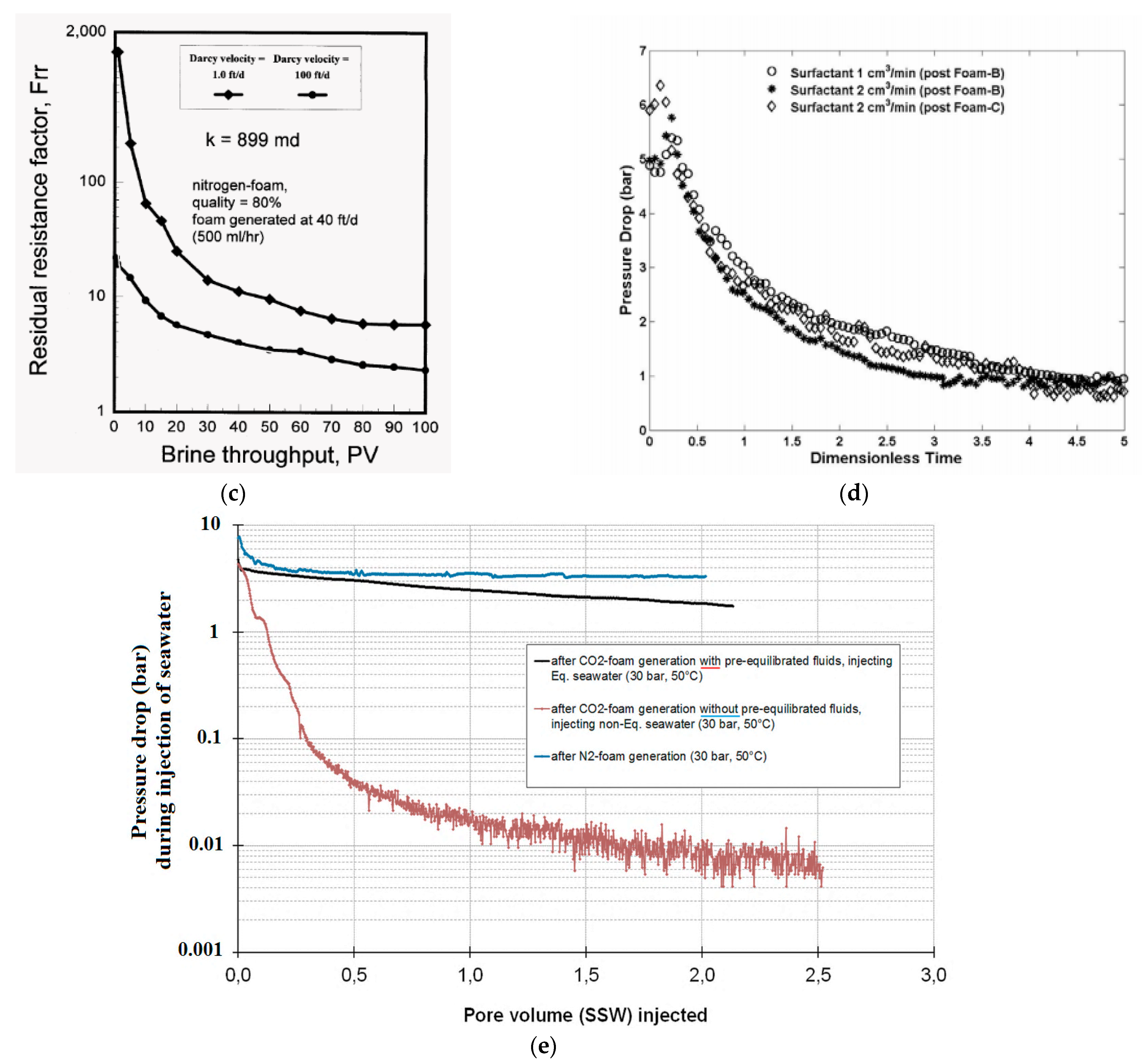
In an extensive report by Seright [21], the potential of N2-foam as a liquid-blocking agent was experimentally and numerically investigated. The general trends during brine injection after foam placement showed that the residual resistance factors to brine flow decreased as both the injection velocity of the brine and the pore volume throughput increased (see Figure 2c). Nevertheless, in the velocity range of 0.30–30 m/d and up to 100 PVs of throughput, foam persistence (resistance to washout) was not very sensitive to (1) the rate of foam generation, (2) the foam quality, (3) the presence of surfactant (0.03 wt.%) in the brine post-flush, or (4) the surfactant concentration during foam generation (0.3 wt.% and 1 wt.%). Results from tracer studies have indicated that the available pore volume for water flow (after injecting significant pore volumes of surfactant-free brine at low flow rates) remains at an almost constant value close to 30% of the original pore volume. Higher residual resistance factors (i.e., higher pressure gradients and lower liquid mobility) were observed as the core permeability decreased (similar to the findings of Parlar et al. [109]). In the same report, Seright [21] also experimentally studied the water injection resistance after steady-state CO2-foam generation in a Berea sandstone core (482 mD) at 69 and 103 bar backpressure and room temperature using an AOSC14-C16 surfactant. The CO2-foams were reported to be quickly “washed out” from the core as the resistance factor rapidly decreased after a few pore volumes of brine were injected. Surfactant dilution was suggested as the main reason for the decreasing resistance factor with increasing brine throughput. No direct comparison or explanation of the huge difference between the CO2- and N2-foam liquid-blocking abilities were provided. To our knowledge, this was the first investigation that studied the liquid-blocking abilities of foams made of different gas phases within the same study. More recent laboratory studies [45,47,112] which have compared the liquid-blocking abilities of foams made of different gas phases (i.e., CO2-foams versus CH4-foams versus N2-foams) also find the CO2-foams to exhibit the least persistent blocking abilities to subsequent brine injection, possibly due to their relative higher solubilities in water (i.e., dissolution of CO2 into the undersaturated injected water >> CH4 in water > N2 in water), which can provoke foam stability and reduce the magnitude of the liquid-blocking effect (see Figure 2d and Figure 4). Accordingly, these laboratory results seem to support the previous field observations of CO2-foam exhibiting poor/less persistence when a water injection followed the foam treatment, as earlier indicated by Holm and Garrison [107] and Enick and Olsen, [24].
Bhide et al. [113] studied foams for controlling water production and found improved foam stability and washout resistance against subsequent water injection with the use of polymeric surfactants (compared with conventional surfactants). Desorption of polymetric surfactants from the air-water interface into the flowing water was found to be limited and much slower compared to conventional surfactants, which could explain why polymetric surfactants produce more long-lasting foams in the presence of flowing water. However, dissolution of gas (air) from foam was thought to be the most important factor on foam lifetime using polymeric surfactants even at inlet pressures of 2–3 atm. In an experiment with oil present, a very stable emulsion was formed in the presence of surfactant. The problem of emulsion formation was minimized with a pre-flush of brine before foam generation.
Nguyen et al. [74,75] conducted visualization studies of liquid injection following foam with the aid of x-ray computed tomography (CT). Effects of foam quality, foam injection rate, post-foam liquid injection rate, and core heterogeneity on liquid mobility were directly observed and reported. The CT images showed that the injected liquid (both surfactant solution and brine) fingered through the foam rather than displacing it evenly. The observed water fingering behavior was also reported for subsequent surfactant solution injection with CO2-foam in a 1D core experiment by Du et al. [91]. These works started raising important implications and limitations to the current one-dimensional models (assuming uniform sweep of the post-foam brine injection), missing the formation of the fingers and the persistence of foam surrounding the liquid finger during brine injection and, therefore, suggesting that in situ imaging in 2D and 3D are essential for unraveling the mechanisms of foam-acid diversion processes. To date, there is still a general lack of information in the literature concerning foam properties in 2D and 3D models.
More recently, a series of experimental investigations concerning the use of foam as a water blocking/diverting agent in relation to environmental soil and groundwater remediation processes have been reported [36,43,102,114,115]. Several of these studies have extended the experimental setup to include larger 2D sandboxes or 2D glass-bead tanks of rather high permeability. All these experimental investigations show that foam can block/divert water flow. Bertin et al. [115] presented results from visualization experiments of foam and fluid flow in a 2D heterogeneous model made of two sand layers of contrasting permeabilities (Kratio = 5). Foam was generated in the high-permeability (bottom) layer and propagated all the way to the model outlet. Gravity was expected to influence the foam zone, as a “triangular” shaped foam zone was observed overriding the high-permeability layer. More importantly, foam did not penetrate the (upper) low-permeability layer. Following foam generation, a dye tracer was injected at constant velocity. They observed that the injected dye was flowing in all regions of the porous medium, including the zone where foam was present. This confirmed that the water mobility was significantly reduced when foam was present and allowed for a better sweep efficiency of the low-permeability layer by subsequent water. Davarzani et al. [36] showed by tracing tests after strong foam generation in a 2D tank model of glass beads that all the lateral water flow was able to be diverted for several hours due to the presence of strong foam. Surfactant dilution below the CMC due to the injected water was claimed as the main-controlling factor for reduced foam stability and successively reduced blocking abilities. Portois et al. [71] conducted a few sand-column tests to support a foam field pilot for environmental purposes, where the effect of foam on the water hydraulic conductivity was shown (i.e., [102]). The results from the column tests showed that the foam reduced the relative water permeability, krw, by a factor of 100–1000 using a commercially available biodegradable surfactant. A standard Van Genuchten curve, which is frequently used for describing the movement of soil water, was adequate to capture the krw behavior in the presence of foam. However, translating the experimental values to a well in a true field situation was difficult and actual field data was recommended to justify the magnitude reduction in krw and as a function of time. It should be mentioned that the field pilot described by Portois et al. [102] showed a reduction in the relative permeability to water by one hundred times (one month after the injection) and ten times (three months after the injection), demonstrating that foam is an effective water blocking agent that can be optimized further.
Pang et al. [116], Yong-Ge et al. [22] and Chen et al. [117] conducted a series of experiments and numerical investigations focusing on N2-foam and its ability to suppress the development of water-coning/cresting in bottom water reservoirs with both horizontal and vertical well configurations (Figure 1c,d). The results from their experiments and numerical simulations showed that N2-foam, emulsion, and nitrogen (without surfactant) can all repress water-coning/cresting and allow incremental oil production. During the process of foam injection in a bottom-water reservoir, the water cone will be repressed by a high-flow-resistance-region composed of foam and emulsion. The subsequent water will need to flow around the area of high-flow-resistance, which increases the sweep efficiency and potential for enhanced oil recovery. A good understanding of the water-coning/cresting problem and near-wellbore reservoir properties followed by reasonable injection-production parameters and corrected foam placement were stated as the key elements in successful anti-water-coning/cresting treatments. Additionally, all three studies highlighted the need for and importance of comprehensive experimental testing at realistic pressure, temperature, and salinity to evaluate the foam blocking ability in porous media before using foam in the dedicated field. In fact, most of the experimental studies in the literature investigating post-foam liquid injection have been carried out under relatively low pressure and temperature and idealized salinity conditions (Table 1).
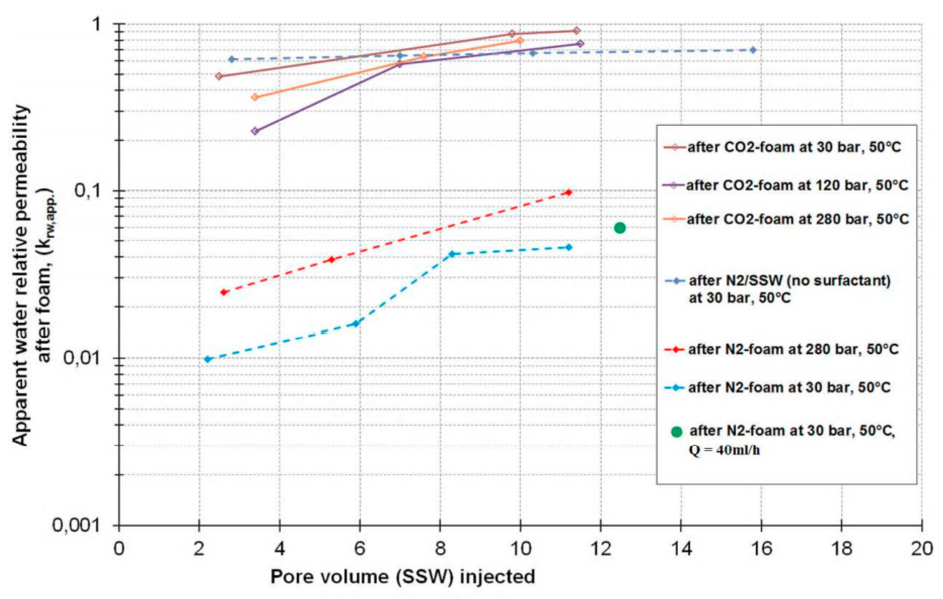
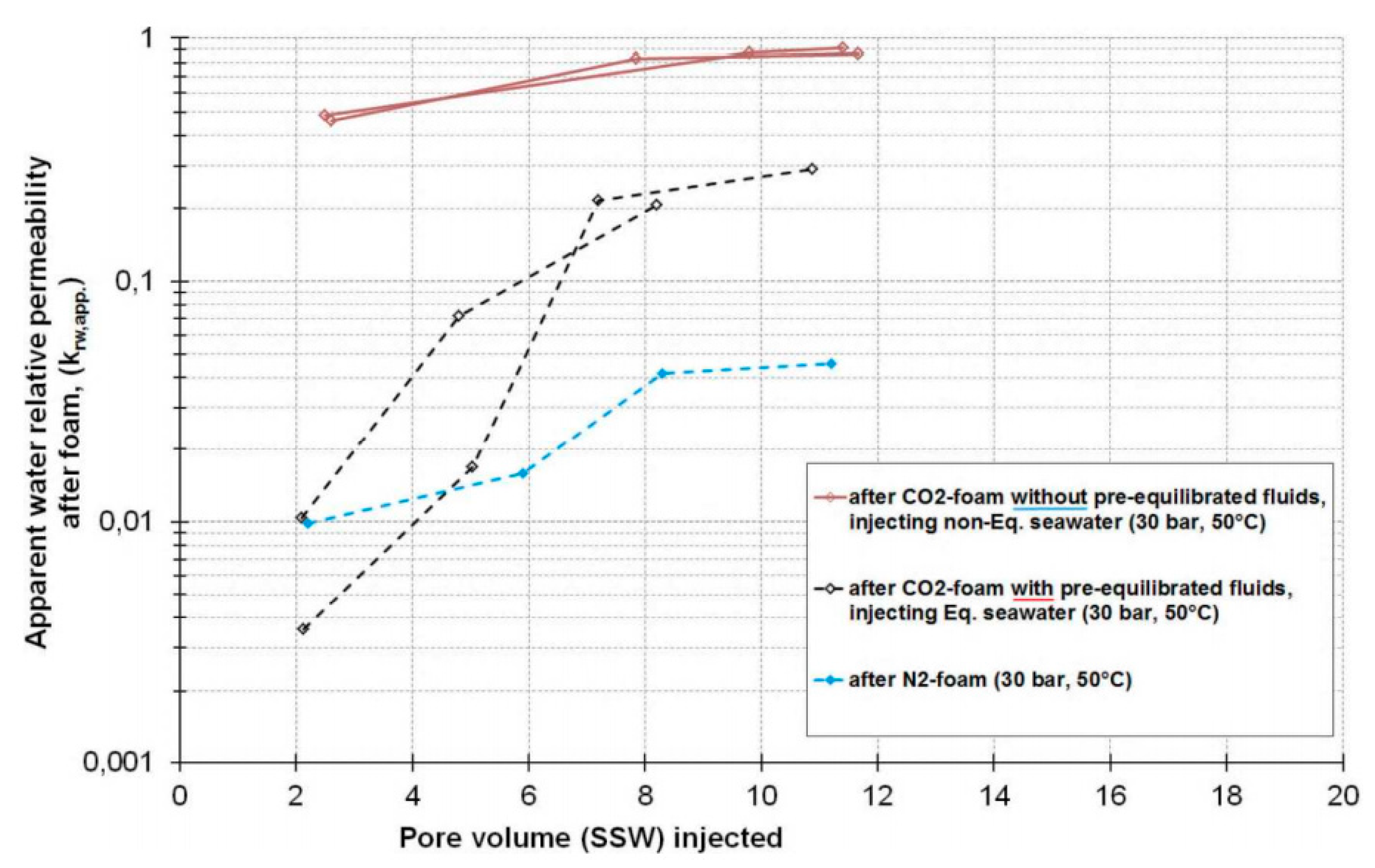
In several experimental foam studies by Aarra et al. [47,112] and Solbakken et al. [45,49], contributions on this subject were derived mainly through laboratory core flooding experiments at elevated pressure and temperature conditions, or in experiments where the system pressure and temperature were varied systematically (over a larger range of P&T conditions than normally reported within the same study). Under some conditions, CO2-foam, N2-foam, and CH4-foam properties and blocking abilities in porous media could be quite similar; however, under other conditions they can be completely different (as noted by these researchers), and this should be important to understand from a fundamental point of view and in terms of scaling when going from lab to field. Figure 3 and Figure 4 show the apparent water relative permeabilities (krw, app.) with pore volume seawater injection derived after different steady-state foam generation experiments. The value of the krw, app. was calculated as kw/Kw (i.e., the effective water permeability normalized to the specific permeability to water and was named “apparent” because the water saturation was not known). Their results can be summarized as follows: (I) The presence of foam (gas, water, surfactant) in the core reduced the seawater permeability in all experiments compared with that in the absence of surfactant. (II) Strong and long-lasting reductions in the seawater permeability were observed after the N2-foams were injected (i.e., krw, app. < 0.1 for more than 11 PV of seawater injected). Increasing the seawater injection rate in one experiment from 8 mL/h to 40 mL/h did not particularly influence the krw, app. (i.e., the green dot in Figure 4 shows krw, app. ~ 0.06 after 12.6 PV). (III) The stability of CO2-foams against seawater injection was significantly poorer compared with that of the N2-foams. (IV) The poor stability of the CO2-foams was seen irrespective of the foam strength during steady-state generation as the seawater permeability became high again only after the injection of a few pore volumes of seawater. Figure 2e shows the abrupt decline in pressure during the initial stage of seawater injection after CO2 foam injection. (V) Significantly improved stability of CO2-foam against seawater injection was demonstrated with pre-saturated fluids (Figure 4). The reduction in seawater permeability was strong and more persistent than that of the CO2-foams without phase-equilibration. (VI) The initial pressure-drop histories supported improved resistance and increased foam stability with pre-saturated fluids, more like those of the N2-foam (Figure 2e). (VII) The experimental results suggest that mass transfer between CO2 and the liquid phase could have a significant impact on foam stability during subsequent liquid injection.
The above survey of experimental works (including Table 1) covers most of the dedicated laboratory works to date addressing the post-foam liquid blocking abilities in porous media for different subsurface application purposes. Nevertheless, evidence of this foam property is also commented on by many others but has often been underreported or simply ignored. In fact, one of the most evident signs of its effect can be easily observed after a foam generation experiment in the laboratory when trying to restore the effective brine permeability back to its original permeability. Normally, at least 50 to 100 pore volumes of brine injection and/or system depressurization are then required to restore the effective brine permeability back to its original permeability, witnessing the strong and long-lasting reduction in water permeability that can occur after a successful foam treatment. The performed experimental works shows that the property of foam as a water blocking agent is a complex issue to understand fully, depending on several physical and chemical factors in close interactions with the properties of the porous media where the event of foam generation, propagation, and stability are determined.
Aside from all these factors and the general difficulties in facilitating comparisons between various experimental studies in the literature, the overall impression is that the generic knowledge and experiences gained from the various applications with respect to foam water blocking can also be adopted for other subsurface water conformance projects. Nevertheless, it is important to emphasize that the performance in laboratory experiments compared to actual field situations could be far from similar, largely due to the differences in scale, reservoir characteristics, foam and fluid properties, injection schemes, and overall objectives of the projects. This highlights the uttermost importance and need to consider a foam application in close connection with reservoir specific properties and processes during the foam-screening process. Consequently, in the evaluation of in situ water blocking abilities of foam, laboratory experiments on rock samples provide the only direct and quantitative measurement of its abilities and should provide the minimum foundation to evaluate before going to field applications.

Table 1.
Summary of experimental and simulation studies on the liquid-blocking effect induced by foam in porous media.
Table 1.
Summary of experimental and simulation studies on the liquid-blocking effect induced by foam in porous media.
| Reference | Application Purpose | Rock Properties | Foam & Fluid Properties | Post-Foam Liquid Injection Conditions | Remarks |
|---|---|---|---|---|---|
| Persoff et al. [20] | Prevention of water-coning | Single core experiments Boise sandstone core L: 60 cm D: 5.1 cm K: 1.3 Darcy φ: 25% | Gas: N2 Brine: 66700 TDS ppm Surfactant: Alkylethoxysulfate (Enordet AES 1215-9N) Surfactant conc.: 1 wt.% Foam generation: co-injection Foam strength: strong foam Without oil | P: ~50 bar T: NS Liquid: brine + surfactant solution Q const.: NS | Key result Figures 8–11 in Persoff et al. (1989). Injection of foamer solution was compared to the injection of surfactant-free water after foam generation in the same experiment. Dilution of surfactant from the core was suggested as the main mechanism controlling liquid saturation and liquid permeability during post-foam liquid injection. Reservoir simulations of foam to combat water coning near-well in an aquifer gas storage reservoir gave favorable results, which suggested foam to be technically feasible and ready for field testing. |
| Kibodeaux et al. [72] | R&D—acid diversion | Single core experiments Berea sandstone cores L: ~12 cm D: ~5.1 cm K: 847 & 92 mD φ: 23 & 18% | Gas: N2 Brine: 1% NaCl + 0.01% CaCl2 Surfactant: non-ionic, PEN-5 Surfactant conc.: 0.5 wt.% Foam generation: pre-gen. Foam strength: strong foams Without oil | P: ~41 bar T: 21 °C Liquid: surfactant solution Q const.: 4.39 & 21.9 m/day | Key result Figures 4–13 in Kibodeaux et al. (1994). This study performed both experiments and sensitivity studies using the fraction-flow model to better understand foam processes for matrix acidization. The sensitivity studies indicated that the mobility of the injected liquid after foam generation is the key to effective diversion of acid in alternating-slug processes. The mobility of subsequent liquid injection is depended on the generated foam properties and how persistent the trapped foam/gas bubbles are during liquid injections. |
| Parlar et al. [109] | R&D—acid diversion | Single & dual core experiments Berea sandstone cores L: 15-30 cm D: 2.54 cm K: 50–1200 mD φ: 18–22% | Gas: N2 Brine: 2% KCl Surfactant: NS Surfactant conc.: 1 wt.% Foam generation: pre-gen. Foam strength: strong foams Without oil | P: ~34 bar T: 21 °C Liquid: surfactant solution Q const.: 0.6–28 m/day | Key result Figures 3–6, 14 and 15 in Parlar et al. (1995). The pressure gradient during post-foam liquid injection was independent of both the total foam injection rate and post-foam liquid rate and was found to be a function of absolute permeability only for fixed surfactant chemistry and decreases as nearly as square root of permeability. This was interpreted as the minimum pressure gradient for foam mobilization. For different surfactant, the behavior was the same except the magnitude of the pressure gradient was different. Liquid diversion was sensitive to foam slug size and surfactant pre-flush. In the optimized diversion experiments reported, nearly 90% of the post-foam liquid could be diverted to low permeability core. |
| Zeilinger et al. [73] | R&D—acid diversion | Single core experiments Berea sandstone core L: 20.3 cm D: 2.54 cm K: 700 mD φ: 20% | Gas: N2 Brine: 3% NaCl + 0.01% CaCl2 Surfactant: non-ionic, PEN-5 Surfactant conc.: 0.5 wt.% Foam generation: pre-gen. Foam strength: strong foams Without oil | P: ~41 bar T: 21 °C Liquid: surfactant solution Q const.: 0.78–3.9 m/day | Key result Figures 12–18 in Zeilinger et al. (1995). Effect of shut-in period, post-foam liquid injection rate, foam quality and gas dissolution on the post-foam liquid injection pressure gradient were experimentally elucidated. The most dominant mechanism found to control foam stability and in maintaining the fixed pressure gradient during post-foam liquid injection was gas dissolution into the injected liquid. No significant effect of shut-in period and only weak correlation with liquid injection rate and foam quality were obtained. Foam-process modeling on laboratory and field scales were tested with different models and implications from lab to field in terms of geometry of flow were discussed. |
| Seright [21] | R&D—fluid diversion techniques in oil recovery | Single core experiments Berea sandstone cores L: ~15 cm D: ~3.7 cm K: 80–899 mD φ: 18.5–23.5% Indiana Limestone core L: ~15 cm D: ~3.7 cm K: 7.5 mD φ: 17.0% | Gas: N2 & CO2 Brine: 1% NaCl + 0.1% CaCl2 Surfactant: anionic, AOSC14-C16 Surfactant conc.: 0.3 & 1.0 wt.% Foam generation: co-injection Foam strength: strong foams Without oil | N2-foam: P: ~50 bar T: 40 °C Liquid: brine & surfactant Q const.: 0.30 & 30 m/day CO2-foam: P: 69 & 103 bar T: 22 °C Liquid: brine Q const.: 0.024 & 2.33 m/day | Key result Figures 82–87 and Table 29 & C-2 in Seright (1996). Foam persistence (resistance to washout) can be slightly enhanced by generating foams at low quality (50%), at high surfactant concentration (1 %), or by injecting dilute surfactant solutions (0.03 % instead of brine). Also, using moderate-to-low injection velocity of brine provided higher and more long-term reduction in brine mobility. CO2 foam exhibited lower/poorer liquid blocking abilities than N2-foam. Residual resistance factors during brine injection after foam placement decreased as the permeability increased. The results from experimental studies were used in numerical analyses to establish whether foams can exhibit placement properties that are superior to those of gellants. Compared with water-like gellants, foams showed better placement properties when the permeabilities were 7.5 mD or less in the low-permeability zones and 80 mD or more in the high-permeability zones. |
| Bhide et al. [113] | R&D—water-control during oil production | Single sand pack experiments Unconsolidated sand packs L: 61 cm K = 5.0–7.0 Darcy φ: 40% | Gas: air Brine: 5% NaCl/DI Polymeric surfactants: Several Concentration: 0.5/2 wt.% Foam generation: SAG Foam strength: strong foams With & without oil | P: atm. T: room Liquid: surfactant & brine Q const.: 1.8–113 m/day | Key result Figures 4b,c, 5b, 6, 8–11 in Bhide et al. (2005). Foams stable to washout with water were shown by using polymeric surfactants. The washout stability was due to almost irreversible adsorption of polymeric surfactants at the air-water interface. Foam dissolution into flowing water was observed to be a factor limiting the foam lifetime of polymeric surfactants. |
| Nguyen et al. [74,75] | R&D—foam-acid diversion and IOR | Single & dual core experiments Berea sandstone cores K: 1420 & 1910 mD Bentheimer sandstone core K: 1010 mD Composite cores Non-communicating double layer core (K ratio = 1200: 19.5 mD) Communicating double layer (K ratio = 9010:127 mD) | Gas: N2 Brine: 1.95% NaCl Surfactants: SDS Concentration: 0.023 wt.% Foam generation: co-injection Foam strength: strong foams Without oil | P: atm. T: room Liquid: surfactant & brine Q const.: 0.94 & 1.87 m/day | Key result figures in Nguyen et al., (2005, 2009). CT images showed that post-foam liquid injections (surfactant solution and brine) fingers through the foam rather than displacing it evenly. Gas expansion was expected to have strong effects on the fingering process as observed in the laboratory experiments under these conditions. The role of core heterogeneity on liquid mobility was more complex/inconclusive. |
| Du et al. [91] | R&D—CO2-foam for EOR and fluid diversion | Bentheimer sandstone core L: 17 cm D: 4.4 cm K: 1200 mD φ: 23% | Gas: CO2 Brine: 0.26 M NaCl Surfactants: SDS Concentration: 0.037 M Foam generation: co-injection Foam strength: strong foams Without oil | P: atm.-5barg T: 20 °C Liquid: surfactant solution Q const.: 1 & 2 mL/min | Key result Figures 5 and 6 in Du et al., (2007). CT images showed strong fingering behavior for subsequent surfactant solution injections in CO2-foam-filled core. Foam mobility is thus, much lower than liquid flow in porous media, which is essential for the successful applications of foam in EOR and acid diversion. |
| Pang et al. [116] | Prevention of water-coning/cresting in bottom water reservoir | Single sand pack experiments Unconsolidated sand packs L: 60 cm K = 3.0 Darcy φ: 30% | Gas: N2 Brine: Formation water (NS) Surfactant: Sulfonate Concentration: 0.4 wt.% Foam generation: pre-generated Foam strength: strong foams With and without oil | P: 10 bar T: 60 °C These experiments did not evaluate post-foam liquid blocking abilities (only foam generation mode). | Results of numerical simulations showed that N2- foam and nitrogen can both effectively repress water-coning for 20 days and allow incremental oil production in a bottom water reservoir. The effective range of N2- foam is wider in the horizontal direction and the declining degree of water-coning is greater in the vertical direction. |
| Aarra et al. [112] | Reservoir condition experiments of foam properties and performance in relation to EOR applications in carbonate material. | Single core experiments Outcrop Limestone core L = 30 cm K = 59–105 mD φ: 13.7–15.2% Reservoir material L: 20.2 cm (4 plugs) K = 192 mD φ: 29.8% | Gas: CO2 and CH4 Brine: Seawater/Formation water Surfactant: AOSC14-C16 Surfactant conc.: 0.5 wt.% Foam generation: co-injection/pre-generation Foam strength: strong foams With remaining oil saturation | P: 277 bar T: 100 °C Liquid: seawater (without surfactant) - | Key result Figures 6, 8 and 11 in Aarra et al., (2011). Water-blocking ability of CO2- and CH4-foam was different. For similar pressure gradients, the water injection rate with CO2-foam in the core were significantly higher compared with the CH4-foam. The increased injection rate was suggested due to larger CO2 dissolution in seawater compared with CH4 in water. |
| Aarra et al. [47] | R&D—CO2-foam and N2-foam properties in porous media in relation to EOR/various subsurface applications. | Single core experiments Berea sandstone core L = 26.35 cm K = 1011 mD φ: 22.3% | Gas: CO2 and N2 Brine: Seawater (~36,000 ppm) Surfactant: AOSC14-C16 Surfactant conc.: 0.5 wt.% Foam generation: co-injection Strong and weak foam generation Without oil present | P: 30, 120 and 80 bar T: 50 °C Liquid: seawater (without surfactant) With and without pre-saturated fluids - Q const.: 0.133 mL/min Equal to the surf. inject. rate during generation. | Key result Figures 8 and 9 in Aarra et al., (2014). N2-foams displayed greater resistance and stability than CO2-foams against post-foam seawater injection. Mass transfer was indicated to play a major role on the CO2-foam stability during subsequent seawater injection. Using pre-equilibrated fluids significantly improved the stability of the CO2-foams to resist/block the injection of seawater. |
| Solbakken [45] | R&D—CO2-foam and N2-foam properties in porous media in relation to subsurface applications. | Same core material as used in Aarra et al. (2014) [47] | Same foams & fluids as used in Aarra et al. (2014) | Same conditions as used in Aarra et al. (2014) | Key result Figures 8.4, 8.7 and 8.8 in Solbakken (2015). Supplementary results, details and discussions (from that reported in Aarra et al., 2011, 2014) are given herein. The thesis also provides relevant/general background material about foam in porous media. |
| Bertin et al. [115] Similar experimental studies in 2D models can be found in: Aranda et al. [114] Davarzani et al. [36] | Foam for environmental remediation | 2D heterogeneous sand model (2 layers) L: 95 cm, H: 50 cm Thickness: 2 cm K ratio = 1:5 φ: NS | Gas: air Triton X-100 (non-ionic surf.) Conc.: 1.5g/L (10 times CMC) in pure water Foam generation: Co-injection | P: atm. T: 20 ± 2 °C Water with a salt-dye Q const.: 11 mL/min | Key result Figures 6 and 7 in Bertin et al., (2017). Experiments performed with a 2D laboratory model consisting of two layers with different properties, highlighted that foam is generated in the high-permeability layer and will divert flow towards the low-permeability region. This behavior is of great interest for the remediation of heterogeneous polluted soils. |
| Portois et al. [71] | Foam for environmental remediation | Column experiments in unconsolidated sand L = 12 cm K = 95 Darcy φ = 31% | Gas: Air Brine: Pure water Surfactant: RES-OLUTIONS, GROUPE RESO, France – (commercially available blend; anionic, zwitterionic, non-ionic) Surfactant conc.: 0.75 wt.% Foam generation: pre-generated | P: atm. T: 20 ± 2 °C Liquid: Pure water | Key result Figures 4, 6 and 7 in Portois et al., (2018b). krw reached a value 3 order of magnitude lower than the one-phase water flow. This proves the effectiveness and the relevance of using foam to reduce the water mobility in a foam-saturated porous media. The major effect of foam is to reduce the value of Sw that directly leads to a reduction of krw. This also suggests that, despite low krw values, the water flow could be easier through the residual water (along lamellae) than displacing the foam. The remaining major difficulty seems to be the foam propagation at distance which can be increased, may be through SAG or some variations of the injection rate were suggested. |
| Chen et al. [117] | Prevention of water-coning/cresting in bottom water reservoir | Single & dual flow experiments in artificially pressed cores K: 1000 & 2000 mD Two-dimensional visual cell | Nitrogen foam is composed of 0.5 wt% Zy-21120, formation water (223,825 ppm) and nitrogen gas. Pre-generated foam injection Foam strength: strong foams With oil present | P: 20 bar T: 20 °C Q const.: 3–9 mL/min | Key result Figures 8, 9 and 15–17 in Chen et al., (2021). Both foam and emulsion injection have a plugging effect on water and effectively increase the swept volume and oil recovery. Foam blocking capacity is somewhat rate dependent. Foam will be directly displaced in large quantities under higher flow rate. A smaller flow rate can guarantee a slower increase in water cut and higher oil production. |
NS = Not Stated.
5. Sensitivity of Governing Parameters and Mechanisms to Foam Stability in Porous Media during Subsequent Liquid Injection
The foams generated for water conformance applications must be very stable to withstand exposure to reservoir conditions and subsequent flow dynamics over potentially long periods. The stability and durability of a foam treatment is therefore a key question for all intended field applications. Cases are reported of foam being able to resist water flow at substantial pressure gradients, injection velocities, and time. In other cases, foam water resistance has been rather limited and/or very poor (Table 1). Consequently, the performance of foam as a water controlling agent in porous media is still controversial and difficult to predict.
The current literature on foam as a liquid controlling agent in porous media (Table 1) has studied the sensitivity to many parameters during post-foam liquid injection (e.g., injection type, rate, time, solvent, surfactant chemistry, foam composition, rock permeability, pressure, and temperature). Based on these works, the most frequent physical and chemical pore scale mechanisms discussed in relation to the effectiveness of foam for impeding water-flow in porous medium have been the post-foam liquid injection mode (Section 5.1), surfactant dilution (Section 5.2), and gas component effects (Section 5.3). Understanding the role and impact of parameters and mechanisms under different conditions is important to secure and optimize foam treatments for water mobility control, if possible. However, resolving the sensitivity of these mechanisms of foam water mobility control could be quite difficult, because in most cases in situ foam properties (e.g., texture) are unknown. Additionally, to date, no generalized theory describing the stability of all foam systems exist.
In Section 5.1, Section 5.2 and Section 5.3, the most governing mechanisms will be explained in more detail, and ways to improve foam water controlling capabilities in porous media are suggested.
5.1. Post-Foam Liquid Injection Mode
The way the post-foam liquid injection is carried out may be the most influential parameter with respect to foam durability, controlling the onset and extent of foam mobilization and/or foam destruction. On the positive side, this may also be the one parameter that is easiest to address.
Typical variables within the stage of liquid injection include the (I) type/point of liquid injection after foam placement, (II) applied pressure gradients, and (III) properties of the liquid injected.
- (I)
- It is generally accepted that with a “closed” liquid flow, where the injected liquid is forced to flow directly into the placed foam, the foam can be more easily mobilized and washed away from that zone and/or be destroyed due to the viscous force interactions between the flowing liquid and the foam. In contrast, the mobilization and/or destruction of the foam can be more limited in the case of an “open” flow, where the flow of liquid can be directed into an area other than the placed foam. For the latter case, advection-diffusion phenomena can dominate the coalescence dynamics of the foam, leaving the foamed zone plugged for an extended length of time after treatment if it is unable to be contacted by the injected water.Considering the 1D laboratory experiments in homogeneous core plugs and the method normally used to conduct the post-foam liquid injection, where the injected liquid is forced to flow through the foam, this is probably therefore a severe test of foam blocking durability. Additionally, it may not necessarily be representative for field applications in terms of heterogeneity and flexibility in the injection mode. The traditional laboratory core flooding test method should therefore be challenged a bit further and extended to dual core flooding setups or other 2D and 3D porous models, allowing for a systematic understanding and comparison of “open” and “closed” liquid injections. Some experimental works and field observations provide some additional viewpoints on these matters [20,36,40,71,74].
- (II)
- Foam texture itself is sensitive to pressure gradients (e.g., varying injection velocity). The increase in liquid pressure can lead to (1) displacement of foam bubbles and/or (2) coalescence/collapse of foam bubbles. Both events can potentially lead to reduced foam persistency and water blocking capabilities. Resolving the differences and magnitude of likely impacts between these two events (i.e., 1 or 2) is decisive to better predict and improve the foam treatment. Resolving the differences is, however, inherently difficult because in most cases foam texture in situ is unknown. The dependency of the applied pressure gradients and foam texture during post-foam liquid injection is therefore not well-established in the literature. Likewise, foam strength during generation cannot be used interchangeably to predict foam stability and post-foam water blocking abilities. From a general point of view, it should be reasonable to expect that more bubbles per area gives a stronger water blockage compared to fewer bubbles per area under otherwise similar conditions. The pioneering theoretical work by Rossen [110] is recommended reading for a better understanding of the fundamentals and assumptions behind the minimum pressure gradient required to mobilize and/or trap foam in porous media.Parlar et al. [109] found that the liquid injection rate following N2-foam injection did not affect the final pressure drop across the core. Similar observations with a doubling in the liquid injection rate (from 60 mL/h to 120 mL/h) were also reported by Nguyen et al. [75]. In Solbakken [45], a seawater injection rate of 8 mL/h versus 40 mL/h following N2-foam generation showed relatively similar krw,app. after the injection of more than 10 pore volumes of seawater (see Figure 3). The fact that the water-blocking effect was not very sensitive to the liquid injection rate in this 1D laboratory core plug experiment may indicate that designated liquid flow paths were established, which displaced some foam out of the core but leaving most of the foam intact and not in direct contact with the injected liquid.Some experimental works have indicated the magnitude of the pressure gradient during post-foam liquid injection in sandstone to be a function of the trapped foam saturation, which varies with the absolute permeability of Berea sandstone [21,72,109]. Trapping of foam bubbles is naturally linked to the foam properties obtained with a fixed surfactant chemistry and the specific pore attributes from where the foam resides. Given the specific dependencies of foam performance, this explains the need for and importance of considering reservoir specific material and conditions during the foam-screening process [37,38,39,78].The length dependence of the core material on water blockage has, to date, not been investigated. For comparison, the length dependence of gas blockage has been investigated, and increasing gas blockage with core length was found [118,119,120]. Foam propagation (i.e., extension of the foamed zone) some distance from the wellbore and into the formation seems therefore important for improving foam wash-out stability and sustaining the water blocking-effect. In general, foam field trials (past and present) lack good information and understanding about the rate and extent of foam propagation, and future foam pilots are encouraged to include observation wells to gain more information of the field-scale foam propagation [64,118,121,122].
- (III)
- How persistent the foam is to subsequent liquid injection also depends on the properties of the liquids injected. Raza [94] showed that foam in porous media restricts the flow of various fluids differently. Flow of gas was restricted the most and the restriction may last for an indefinitely long period of time. The flow of water was restricted but the restriction lessens with time as foam decays. The flow of hydrocarbon solvents was also restricted, but the restriction was of a temporary nature. The flow behavior of isopropyl alcohol was drastically different; it immediately entered the sand pack and the injectivity sharply increased, indicating the most severe destruction/collapse of foam. Others have also indicated that lighter hydrocarbons/shorter chain alkanes or alcohols may be the most detrimental to foam stability, although, the interactions in porous media are complex and not fully understood [20,57,58,59,113,123].
5.2. Surfactant Dilution
Another main mechanism that frequently has been discussed in relation to reduced foam stability and persistence (resistance to washout) during subsequent liquid injections is surfactant dilution [20,21,36,75,113].
During the injection of large volumes of brine (without surfactant), it should be reasonable to expect that the concentration of surfactant in the flooded zone would reduce, and that this would cause some degree of foam destabilization, thus reducing the trapped gas-saturation and increasing the water relative permeability.
In Davarzani et al. [36], surfactant dilution below the CMC due to the injected water was claimed as the main-controlling factor for reduced foam stability and successively reduced blocking abilities. Experimental results by Seright [21] showed that foam persistence could be enhanced by injecting diluted surfactant solutions (0.03% instead of brine). In Nguyen et al. [75] and Solbakken [45], no significant differences in foam stability against liquid injection were indicated when pure brine was compared with the injection of surfactant solution, suggesting that surfactant dilution by water does not always cause the foam to become less stable.
When low water relative permeability remains in a core flooding experiment even after extensive water injection, it can be speculated the amount of surfactant in the core sample is not yet too critically low for regeneration to take place and/or for preserving foam stability. For instance, desorption of surfactant from the rock surfaces might be a very slow process, as indicated by Bai et al. [124] and Bhide et al. [113]. It is also well-known that foams can be generated and remain semi-stable in bulk and porous media experiments using low concentrations of surfactant [11,23,44,45,46,59,66,86,125].
If designated liquid flow paths were established during post foam liquid injection, less foam/surfactant would be displaced out of the core, leaving foam/surfactant left in the core and in little contact with the injected liquid. A direct conclusive comparison of foam experiments from the different studies using different surfactants and experimental procedures may render this difficult anyway. A portion of the difference in foam water mobility control could, for instance, also be attributed to the type of surfactant being used.
Further studies should try to determine the magnitude of surfactant dilution during post foam liquid injection. For that, accurate measurements and analyses of the effluent surfactant concentration are desirable.
5.3. Gas Component Effects
Other decay mechanisms of foam important to water-blocking seem to be associated with different kinds of mass transfer due to non-equilibrium conditions (e.g., in the form of gas or water dissolution, inter-bubble diffusion, and/or liquid or gas evaporation due to changes in the chemical potential).
Comparative studies have showed that liquid injection was significantly more severe for the stability of CO2-foams compared to N2-foams [45]. Accordingly, avoiding gases in the foam system with high solubility and high diffusivity in liquids could produce more long-lived foams with stronger water-blocking effects. Similar main decay mechanisms have also been suggested for gas-blocking foams [119]. Use of partly equilibrated liquids (from an injector side) and/or addition of polymers to the foam system (mainly from the producer side) could therefore compromise to maintain foam stability and strengthen water-blocking ability. It is interesting to note that certain field results also appear to support the laboratory-derived results concerning poor water-blocking capabilities of CO2-foam [24,107]. Consequently, it seems instructive to compare different types of foam in the same study for an improved quantitative understanding and evaluation of the foam performance.
It should also be noted that gas expansion is expected to have strong effects under conditions with low system/application pressure (e.g., where many of the abovementioned visualization studies have been performed for remediation applications). The results may therefore not reflect all foam behaviors in field applications where the pressure and temperature are significantly higher and the porous media properties are different (for instance as noted by Nguyen et al. [74,75]).
6. Summary and Future Research
This review article has summarized the current documented observations of foam as a liquid blocking agent in porous media. The ability of foam to reduce water flow has been clearly demonstrated through numerous experimental and numerical studies accomplished on core-to-field scales. Nevertheless, being the least explored property of foam, its effect and potential have often been underreported or simply ignored.
As a liquid controlling agent in porous media, foam has the potential for industrial processes that involve fluid injections and/or fluid withdrawals from porous subsurface formations, such as improved/enhanced oil recovery (IOR/EOR), matrix-stimulation treatments, underground storage of CO2, hydrogen, compressed-air or natural gas withdrawal, geothermal energy, and/or contaminated soil-groundwater remediation processes with unwanted or unfavorable aquifer impacts.
The overall energic, economic and environmental incentives that can come from applying foam in spesific reservoir applications are associated with (I) improved liquid utilization, (II) reduced water management, and/or (III) improved operational turnover (compared to what could be achieved without applying foam and/or other water-blocking techniques).
Foam for underground applications does not need to be limited to conventional uses but can be applied wherever/whenever a demand is present. A possible application where foam technology could advance in the future is in CO2 sequestration projects, for instance, during CO2 storage in aquifers and/or hydrocarbon reservoirs. Here, backflow of fluids (e.g., brine, CO2 plume, oil) due to intermittent injection scenarios might be temporarily controlled with foam. Reducing liquid inflow and/or loss of wellbore-reservoir energy during planned stops and restarts can ensure injectivity is maintained. Because the cycles in some of these applications can occur on shorter time scales, requirements for foam stability and surfactant might be reduced.
For the qualification process, foam would, among other things, need to show promising results in the lab before it could be applied in the field. A thorough testing matrix with field specific demands and conditions should therefore be developed and anchored with inputs from researchers, field engineers, and field management. Nevertheless, the relevance of the laboratory data and numerical assessments of water mobility control by foam requires support and confirmation from actual field tests. Consequently, more field demonstrations are needed to increase the confidence of using foam as a liquid controlling agent.
To determine the potential of foam in terms of liquid flow control, parameters, properties, and mechanisms that affect foam stability and persistence after the foam generation and placement process needs to be thoroughly investigated and understood. Nevertheless, only a few systematic and comprehensive studies on the effect of post-foam liquid injection in porous media have been executed. There is still a general lack of information in the literature concerning the fundamental physical and chemical mechanisms contributing to the post-foam liquid mobility control. Furthermore, the existence of several discrepancies between the experimental results and the numerical calculations indicates that the state-of-the-art knowledge regarding modelling of liquid flow dynamics in porous media in the presence of foam is not commensurate with the complexity of the issue. Clearly, further research is needed.
Further research should, through systematic core flooding experiments, focus on distinguishing more accurately between the dominating dynamics, properties, parameters, and mechanisms of post-foam liquid injection. Better understanding of the magnitude difference between foam mobilization and foam coalescence/collapse during post foam liquid injection is of interest to better tune the models. Optimally, this should be systematically monitored by pressure ports along the porous media, in situ saturation measurements, and visualization techniques. The latter measurement techniques can, however, to some extent, be compensated for by accurate measurements of the effluent fluids, including analyses of produced amounts of gas, liquid, and surfactant concentrations with time. Observations and analyses of foam texture dynamics under experimental conditions (e.g., from view-cells or tubing coils mounted at the core outlet) may also aid in providing some information about foam properties and stability in situ. Sensitivity studies should be performed to validate the physical experiments and models. The past decade has seen several studies attempting to improve and strengthen foam properties and these studies need to continue to advance in the use of surfactant formulas, the addition of polymer to the foaming solution, and the use of nanoparticles. A few studies on surfactant stabilized N2/CO2-foams, which replace part of the CO2 content with N2 to overcome the CO2-foam instabilities, have also shown potential.
Dependency of scale, geometry, and rock heterogeneity on the liquid flow dynamics in the presence of foam should be studied further. No general recommendations on these matters have been given in the literature so far. Accordingly, the traditional laboratory core flooding test method of foam could therefore be challenged a bit further and extended, for instance, by longer/larger core samples with supportive monitoring techniques, dual core flooding setup, radial geometry, and/or other 2D and 3D porous models, allowing new/complimentary understandings and developments of post-foam liquid injection that can help to bridge the gap between lab and field results and help mature this technology/tool for more commercial applications.
Funding
This research received no external funding.
Data Availability Statement
No new data were created in this review.
Conflicts of Interest
The author declares no conflict of interest.
References
- Farajzadeh, R.; Kahrobaei, S.; Eftekhari, A.A.; Mjeni, R.A.; Boersma, D.; Bruining, J. Chemical enhanced oil recovery and the dilemma of more and cleaner energy. Sci. Rep. 2021, 11, 829. [Google Scholar] [CrossRef]
- Farajzadeh, R.; Glasbergen, G.; Karpan, V.; Mjeni, R.; Boersma, D.; Eftekhari, A.; Garcia, A.C.; Bruining, J. Improved oil recovery techniques and their role in energy efficiency and reducing CO2 footprint of oil production. J. Clean. Prod. 2022, 369, 133308. [Google Scholar] [CrossRef]
- Grandell, L.; Hall, C.A.; Höök, M. Energy Return on Investment for Norwegian Oil and Gas from 1991 to 2008. Sustainability 2011, 3, 2050–2070. [Google Scholar] [CrossRef] [Green Version]
- Guo, L.; Liu, Y.; Luo, S.; Wei, L. Energy Saving and Consumption Reduction of Oilfield Pressurized Water Injection System. Ekoloji 2019, 28, 759–765. [Google Scholar]
- Masnadi, M.S.; Brandt, A.R. Climate impacts of oil extraction increase significantly with oilfield age. Nat. Clim. Chang. 2017, 7, 551–556. [Google Scholar] [CrossRef]
- Voldsund, M.; Ertesvåg, I.S.; He, W.; Kjelstrup, S. Exergy analysis of the oil and gas processing on a North Sea oil platform a real production day. Energy 2013, 55, 716–727. [Google Scholar] [CrossRef]
- Lake, L.; Johns, R.T.; Rossen, W.R.; Pope, G.A. Fundamentals of Enhanced Oil Recovery. Soc. Pet. Eng. 2014. [Google Scholar] [CrossRef]
- Skauge, T.; Vik, B.F.; Ormehaug, P.A.; Jatten, B.K.; Kippe, V.; Skjevrak, I.; Standnes, D.C.; Uleberg, K.; Skauge, A. Polymer Flood at Adverse Mobility Ratio in 2D Flow by X-ray Visualization. In Proceedings of the SPE EOR Conference at Oil and Gas West Asia, Muscat, Oman, 31 March–2 April 2014. Paper SPE 169740. [Google Scholar]
- Vik, B.F.; Kedir, A.; Kippe, V.; Sandengen, K.; Skauge, T.; Solbakken, J.; Zhu, D. Viscous Oil Recovery by Polymer Injection; Impact of In-Situ Polymer Rheology on Water Front Stabilization. In Proceedings of the SPE Europec 80th EAGE Conference and Exhibition, Copenhagen, Denmark, 11–14 June 2018. Paper SPE 165296. [Google Scholar]
- Singhal, A.K. Water and Gas Coning/Cresting: A Technology Overview. J. Can. Pet. Technol. 1996, 35. [Google Scholar] [CrossRef] [Green Version]
- Smith, D.H.; Jikich, S.A. Foams and Surfactants for Improved Underground Storage of Natural Gas by Blockage of Water Coning. In Proceedings of the SPE Eastern Regional Conference and Exhibition, Pittsburgh, PA, USA, 2–4 November 1993. Paper SPE 26908. [Google Scholar]
- Edlmann, K.; Hinchliffe, S.; Heinemann, N.; Johnson, G.; Ennis-King, J.; McDermott, C. Cyclic CO2—H2O injection and residual trapping: Implications for CO2 injection efficiency and storage security. Int. J. Greenh. Gas Control 2019, 80, 1–9. [Google Scholar] [CrossRef] [Green Version]
- Loizzo, M.; Lecampion, B.; Bérard, T.; Harichandran, A.; Jammes, L. Reusing O&G-Depleted Reservoirs for CO2 Storage: Pros and Cons. SPE Proj. Facil. Constr. 2010, 5, 166–172. [Google Scholar]
- Miri, R.; Hellevang, H. Salt precipitation during CO2 storage—A review. Int. J. Greenh. Gas Control 2016, 51, 136–147. [Google Scholar] [CrossRef]
- Buwauqi, S.; Al Jumah, A.; Shabibi, A.; Harrasi, A.; El-Fattah, M.A.; Kalyani, T.; Fahmy, A. Case Study: How the Newest Generation of Autonomous Inflow Control Device Helps to Control Excessive Wells Water Production within a Major Sultanate of Oman Oilfield. In Proceedings of the Offshore Technology Conference Asia, Virtual and Kuala Lumpur, Malaysia, 21 March 2022. Paper Number: OTC-31483-MS. [Google Scholar] [CrossRef]
- Giger, F. Horizontal Wells Production Techniques in Heterogeneous Reservoirs. In Proceedings of the SPE 1985 Middle East Oil Technical Conference and Exhibition, Manama, Bahrain, 11–14 March 1985. SPE 13710. [Google Scholar] [CrossRef]
- Luo, W.; Li, H.T.; Wang, Y.Q.; Wang, J.C. A new semi-analytical model for predicting the performance of horizontal wells completed by inflow control devices in bottom-water reservoirs. J. Nat. Gas Sci. Eng. 2015, 27, 1328–1339. [Google Scholar] [CrossRef]
- Feller, F. WIN WIN—Wind-Powered Water Injection. In Proceedings of the Offshore Mediterranean Conference and Exhibition, Ravenna, Italy, 29 March 2017. Paper Number: OMC-2017-721. [Google Scholar]
- Riboldi, L.; Völler, S.; Korpås, M.; Nord, L.O. An Integrated Assessment of the Environmental and Economic Impact of Offshore Oil Platform Electrification. Energies 2019, 12, 2114. [Google Scholar] [CrossRef] [Green Version]
- Persoff, P.; Pruess, K.; Benson, S.M.; Wu, Y.S.; Radke, C.J.; Witherspoon, P.A.; Shikari, Y.A. Aqueous Foams for Control of Gas Migration and Water Coning in Aquifer Gas Storage. In Proceedings of the International Gas Research Conference, Tokyo, Japan, 6–9 November 1989; Available online: https://escholarship.org/uc/item/0nc7h2n0 (accessed on 1 April 2023).
- Seright, R.S. Improved Techniques for Fluid Diversion in Oil Recovery Processes, Final Report, DOE/BC/14880-15, Contract No. DE-AC22-92BC14880, U.S. DOE, January 1996. Available online: https://digital.library.unt.edu/ark:/67531/metadc667143/m2/1/high_res_d/188919.pdf (accessed on 1 April 2023).
- Yong-Ge, L.; Hui-Qing, L.; Zhan-Xi, P. Numerical Simulation of Nitrogen Foam Injection to Control Water Cresting by Bilateral Horizontal Well in Bottom Water Reservoir. Open Fuels Energy Sci. J. 2012, 5, 53–60. [Google Scholar] [CrossRef] [Green Version]
- Aarra, M.G.; Skauge, A.; Martinsen, H.A. FAWAG: A Breakthrough for EOR in the North Sea. In Proceedings of the SPE Annual Technical Conference and Exhibition, San Antonio, TX, USA, 29 September–2 October 2002. Paper SPE 77695. [Google Scholar]
- Enick, R.M.; Olsen, D.K. Mobility and Conformance Control for Carbon Dioxide Enhanced Oil Recovery (CO2-EOR) via Thickeners, Foams, and Gels—A Detailed Literature Review of 40 Years of Research, DOE/NETL—2012/1540; Activity 4003.200.01, Report prepared for the U.S. Department of Energy; NETL: Morgantown, WV, USA, 2012. [Google Scholar]
- Islam, M.R.; Ali, S.F. Mobility control in waterflooding oil reservoirs with a bottom-water zone. J. Can. Pet. Technol. 1987, 26. [Google Scholar] [CrossRef]
- Langaas, K.; Stavland, A. Water Shutoff with Polymer in the Alvheim Field. SPE Prod. Oper. 2020, 35, 335–350. [Google Scholar] [CrossRef]
- McPhee, C.A.; Therain, A.D.H.; Jolly, R.P.S. Foam Flooding of Cores Under North Sea Reservoir Conditions. In Proceedings of the SPE/DOE Enhanced Oil Recovery Symposium, Tulsa, OK, USA, 17–20 April 1988. Paper SPE/DOE 17360. [Google Scholar]
- Sagbana, P.I.; Abushaikha, A.S. A comprehensive review of the chemical-based conformance control methods in oil reservoirs. J. Pet. Explor. Prod. Technol. 2021, 11, 2233–2257. [Google Scholar] [CrossRef]
- Bernard, G.G.; Holm, L.W.; Jacobs, W.L. Effect of Foam on Trapped Gas Saturation and on Permeability of Porous Media to Water. Soc. Pet. Eng. J. 1965, 5, 267–300. [Google Scholar] [CrossRef]
- Holm, L.W. The Mechanism of Gas and Liquid Flow through Porous Media in the Presence of Foam. Soc. Pet. Eng. J. 1968, 8, 359–369. [Google Scholar] [CrossRef]
- Zhdanov, S.A.; Amiyan, A.V.; Surguchev, L.M.; Castanier, L.M.; Hanssen, J.E. Application of Foam for Gas and Water Shut-off: Review of Field Experience. In Proceedings of the SPE European Petroleum Conference, Milan, Italy, 22–24 October 1996. Paper SPE 36914. [Google Scholar]
- Falls, H.; Musters, J.J.; Ratulowski, J. The apparent viscosity of foams in homogeneous bead packs. SPE Reserv. Eng. 1989, 4, 155–164. [Google Scholar] [CrossRef]
- Schramm, L.L.; Wassmuth, F. Chapter 1 Foams: Basic principles. In Foams: Fundamentals and Application in the Petroleum Industry; Schramm, L.L., Ed.; American Chemical Society: Washington, DC, USA, 1994; pp. 3–45. [Google Scholar]
- Kovscek, A.R.; Radke, C.J. Chapter 3 Fundamentals of Foam Transport in Porous Media. In Foams: Fundamentals and Application in the Petroleum Industry; Schramm, L.L., Ed.; American Chemical Society: Washington, DC, USA, 1994; pp. 115–163. [Google Scholar]
- Rossen, W.R. Chapter: Foams in Enhanced Oil Recovery. In Foams: Theory, Measurements, and Applications; Prud’homme, R.K., Khan, S.A., Eds.; Marcel Dekker: New York, NY, USA, 1996; pp. 413–464. [Google Scholar]
- Davarzani, H.; Aranda, R.; Colombano, S.; Laurent, F.; Bertin, H. Experimental study of foam propagation and stability in highly permeable porous media under lateral water flow: Diverting groundwater for application to soil remediation. J. Contam. Hydrol. 2021, 243, 103917. [Google Scholar] [CrossRef] [PubMed]
- Adebayo, A.R. A Graphical Interpretation Technique to Evaluate Strength and Stability of Foam in Porous Media Based on Mobile-Trapped Foam Ratio. Transp. Porous Media 2021, 139, 327–355. [Google Scholar] [CrossRef]
- Adebayo, A.R. Foam Flow in Different Pore Systems—Part 1: The Roles of Pore Attributes and Their Variation on Trapping and Apparent Viscosity of Foam. SPE J. 2021, 26, 3908–3925. [Google Scholar] [CrossRef]
- Adebayo, A.R. Foam Flow in Different Pore Systems—Part 2: The Roles of Pore Attributes on the Limiting Capillary Pressure, Trapping Coefficient, and Relative Permeability of Foamed Gas. SPE J. 2021, 26, 3926–3948. [Google Scholar] [CrossRef]
- Nguyen, Q.P.; Alexandrov, A.; Zitha, P.L.J.; Currie, P.K. Experimental and Modeling Studies on Foam in Porous Media: A Review. In Proceedings of the 2000 SPE International Symposium on Formation Damage Control, Lafayette, LA, USA, 23–24 February 2000. Paper SPE 58799. [Google Scholar]
- Føyen, T.; Alcorn, Z.; Fernø, M.; Barrabino, A.; Holt, T. CO2 mobility reduction using foam stabilized by CO2- and water-soluble surfactants. J. Pet. Sci. Eng. 2020, 196, 107651. [Google Scholar] [CrossRef]
- Jones, S.A.; Laskaris, G.; Vincent-Bonnieu, S.; Farajzadeh, R.; Rossen, W.R. Effect of surfactant concentration on foam: From coreflood experiments to implicit-texture foam-model parameters. J. Ind. Eng. Chem. 2016, 37, 268–276. [Google Scholar] [CrossRef] [Green Version]
- Prieditis, J.; Paulett, G.S. CO2-Foam Mobility Tests at Reservoir Conditions in San Andreas Cores. In Proceedings of the SPE/DOE Eighth Symposium on Enhanced Oil Recovery, Tulsa, OK, USA, 22–24 April 1992. Paper SPE/DOE 24178. [Google Scholar]
- Simjoo, M.; Dong, Y.; Andrianov, A.; Talanana, M.; Zitha, P.L.J. Novel Insight into Foam Mobility Control. SPE J. 2013, 18, 416–427. [Google Scholar] [CrossRef]
- Solbakken, J. Experimental Studies of N2- and CO2-Foam Properties in Relation to Enhanced Oil Recovery Applications. Ph.D. Dissertation, University of Bergen, Bergen, Norway, 2015. [Google Scholar]
- Suffridge, F.E.; Raterman, K.T.; Russel, G.C. Foam Performance Under Reservoir Conditions. In Proceedings of the SPE Annual Technical Conference and Exhibition, San Antonio, TX, USA, 8–11 November 1989. Paper SPE 19691. [Google Scholar]
- Aarra, M.G.; Skauge, A.; Solbakken, J.; Ormehaug, P.A. Properties of N2- and CO2-foams as a function of pressure. J. Pet. Sci. Eng. 2014, 116, 72–89. [Google Scholar] [CrossRef] [Green Version]
- Farajzadeh, R.; Andrianov, A.; Bruining, H.; Zitha, P.L.J. Comparative study of CO2 and N2 foams in porous media at low and high pressure-temperatures. Ind. Eng. Chem. 2009, 48, 4542–4552. [Google Scholar] [CrossRef]
- Solbakken, J.S.; Aarra, M.G. CO2 mobility control improvement using N2-foam at high pressure and high temperature conditions. Int. J. Greenh. Gas Control 2021, 109, 103392. [Google Scholar] [CrossRef]
- Zeng, Y.; Farajzadeh, R.; Eftekhari, A.A.; Vincent-Bonnieu, S.; Muthuswamy, A.; Rossen, W.R.; Hirasaki, G.J.; Biswal, S.L. Role of Gas Type on Foam Transport in Porous Media. Lagmuir 2016, 32, 6239–6245. [Google Scholar] [CrossRef] [Green Version]
- Aronsen, A.S.; Bergeron, B.; Fagan, M.E.; Radke, C.J. The influence of disjoining pressure on foam stability and flow in porous media. Colloids Surf. A Physicochem. Eng. Asp. 1994, 83, 109–120. [Google Scholar] [CrossRef]
- Kedir, A.S.; Solbakken, J.S.; Aarra, M.G. Foamability and stability of anionic surfactant-anionic polymer solutions: Influence of ionic strength, polymer concentration, and molecular weight. Colloids Surf. A Physicochem. Eng. Asp. 2021, 632, 127801. [Google Scholar] [CrossRef]
- Solbakken, J.S.; Skauge, A.; Aarra, M.G. Foam performance in low permeability laminated sandstones. Energy Fuels 2014, 28, 803–815. [Google Scholar] [CrossRef]
- Haugen, Å.; Mani, N.; Svenningsen, S.; Brattekås, B.; Graue, A.; Ersland, G.; Fernø, M.A. Miscible and immiscible foam injection for mobility control in EOR in fractured oil-wet carbonate rocks. Transp. Porous Media 2014, 104, 109–131. [Google Scholar] [CrossRef]
- Talebian, S.H.; Masoudi, R.; Tan, I.M.; Zitha, P.L.J. Foam assisted CO2- EOR; Concepts, Challenges and Applications. In Proceedings of the SPE Enhanced Oil Recovery Conference, Kuala Lumpur, Malaysia, 2–4 July 2013. Paper SPE 165280. [Google Scholar]
- Farajzadeh, R.; Andrianov, A.; Krastev, R.; Hirasaki, G.J.; Rossen, W.R. Foam-oil interaction in porous media: Implications for foam assisted enhanced oil recovery. Adv. Colloid Int. Sci. 2012, 183–184, 1–13. [Google Scholar] [CrossRef] [PubMed]
- Kuhlman, M.I. Visualizing the Effect of Light Oil on CO2 Foams. J. Pet. Technol. 1990, 42, 902–908. [Google Scholar] [CrossRef]
- Schramm, L.L.; Novosad, J.J. The Destabilization of Foams for Improved Oil Recovery by Crude Oils: Effect of the Nature of the Oil. J. Petr. Sci. Eng. 1992, 7, 77–90. [Google Scholar] [CrossRef]
- Vikingstad, K. Static and Dynamic Studies of Foam and Foam-Oil Interactions. Ph.D. Dissertation, University of Bergen, Bergen, Norway, 2006. [Google Scholar]
- Chang, S.H.; Grigg, R.B. Effects of Foam Quality and Flow Rate on CO2- Foam Behaviour at Reservoir Temperature and Pressure. SPE Reserv. Eval. Eng. 1999, 2, 248–254. [Google Scholar] [CrossRef]
- Gauglitz, P.A.; Friedmann, F.; Kam, S.I.; Rossen, W.R. Foam Generation in Homogeneous Porous Media. Chem. Eng. Sci. 2002, 57, 4037–4052. [Google Scholar] [CrossRef]
- Kim, J.S.; Dong, Y.; Rossen, W.R. Steady-State Flow Behavior of CO2 Foam. In Proceedings of the SPE/DOE Fourteenth Symposium on Improved Oil Recovery, Tulsa, OK, USA, 17–21 April 2005. Paper SPE 89351. [Google Scholar]
- Osterloh, W.T.; Jante, M.J. Effects of Gas and Liquid Velocity on Steady-State Foam Flow at High Temperature. In Proceedings of the SPE/DOE Enhanced Oil Recovery Symposium, Tulsa, OK, USA, 22–24 April 1992. Paper SPE 24179. [Google Scholar]
- Skauge, A.; Solbakken, J.; Ormehaug, P.A.; Aarra, M.G. Foam Generation, Propagation and Stability in Porous Medium. Transp. Porous Media 2019, 131, 5–21. [Google Scholar] [CrossRef] [Green Version]
- Alcorn, Z.P.; Fredriksen, S.B.; Sharma, M.; Rognmo, A.U.; Føyen, T.L.; Fernø, M.; Graue, A. An Integrated CO2 Foam EOR Pilot Program with Combined CCUS in an Onshore Texas Heterogeneous Carbonate Field. In Proceedings of the SPE Improved Oil Recovery Conference, Tulsa, OK, USA, 14–18 April 2018. Paper SPE 190204. [Google Scholar]
- Alkan, H.; Goktekin, A.; Satman, A. A Laboratory Study of CO2-Foam Process for Bati Raman Field, Turkey. In Proceedings of the SPE Middle East Oil Show, Manama, Bahrain, 16–19 November 1991. Paper SPE 21409. [Google Scholar]
- Hirasaki, G.J.; Lawson, J.B. Mechanisms of foam flow in porous media: Apparent viscosity in smooth capillaries. Soc. Pet. Eng. J. 1985, 25, 176–190. [Google Scholar] [CrossRef]
- Liontas, R.; Ma, K.; Hirasaki, G.J.; Biswal, S.L. Neighbor-induced bubble pinch-off: Novel mechanisms of in situ foam generation in microfluidic channels. Soft Matter 2013, 9, 10971–10984. [Google Scholar] [CrossRef]
- Mast, R.F. Microscopic behavior of foam in porous media. In Proceedings of the Fall Meeting of the Society of Petroleum Engineers of AIME, San Antonio, TX, USA, 8–11 October 1972. Paper SPE 3997. [Google Scholar]
- Krause, R.E.; Lane, R.H.; Kuehne, D.L.; Bain, G.F. Foam Treatment of Producing Wells to Increase Oil Production at Prudhoe Bay. In Proceedings of the SPE/DOE Eighth Symposium on Enhanced Oil Recovery, Tulsa, OK, USA, 22–24 April 1992. Paper SPE/DOE 21191. [Google Scholar]
- Portois, C.; Boeije, C.S.; Bertin, H.J.; Atteia, O. Foam for Environmental Remediation: Generation and Blocking Effect. Transp. Porous Media 2018, 124, 787–801. [Google Scholar] [CrossRef]
- Kibodeaux, K.R.; Zeilinger, S.C.; Rossen, W.R. Sensitivity Study of Foam Diversion Processes for Matrix Acidization. In Proceedings of the SPE 69th Annual Technical Conference and Exhibition, New Orleans, LA, USA, 25–28 September 1994. Paper SPE 28550. [Google Scholar]
- Zeilinger, S.C.; Wang, M.; Kibodeaux, K.R.; Rossen, W.R. Improved Prediction of Foam Diversion in Matrix Acidization. In Proceedings of the Production Operations Symposium, Oklahoma City, OK, USA, 2–4 April 1995. Paper SPE 29529. [Google Scholar]
- Nguyen, Q.P.; Currie, P.K.; Zitha, P.L.J. Effect of Crossflow on Foam-Induced Diversion in Layered Formations. Soc. Pet. Eng. J. 2005, 10, 54–65. [Google Scholar] [CrossRef]
- Nguyen, Q.P.; Zitha, P.L.J.; Currie, P.K.; Rossen, W.R. CT Study of Liquid Diversion with Foam. SPE Prod. Oper. 2009, 24, 12–21. [Google Scholar] [CrossRef]
- Khatib, Z.I.; Hirasaki, G.J.; Falls, A.H. Effects of Capillary Pressure on Coalescence and Phase Mobilities in Foams Flowing Through Porous Media. SPE Reserv. Eng. 1988, 3, 919–926. [Google Scholar] [CrossRef]
- Ma, K.; Ren, G.; Mateen, K.; Morel, D.; Cordelier, P. Modelling techniques for foam flow in porous media. Soc. Pet. Eng. J. 2015, 20, 453–470. [Google Scholar]
- Mannhardt, K.; Novosad, J.J.; Schramm, L.L. Comparative Evaluation of Foam Stability to Oil. SPE Reserv. Eval. Eng. 2000, 3, 23–34. [Google Scholar] [CrossRef]
- Sun, L.; Bai, B.; Wei, B.; Pu, W.; Wei, P.; Li, D.; Zhang, C. Recent Advantages of surfactant-stabilized N2/CO2 foams in enhanced oil recovery. Fuel 2019, 241, 83–93. [Google Scholar] [CrossRef]
- Ahmed, S.; Elraies, K.A.; Hashmet, M.R.; Shaifan, S.R.B.M.; Hsia, I.C.C.; Bahrim, R.Z.K. Experimental Investigation and Optimization of Polymer Enhanced CO2 Foam Stability and Apparent Viscosity. In Proceedings of the SPE Kingdom of Saudi Arabia Annual Technical Symposium and Exhibitions, Dammam, Saudi Arabia, 24–27 April 2017. Paper SPE 188018-MS. [Google Scholar]
- Bhatt, S.; Saraf, S.; Bera, A. Perspectives of Foam Generation Techniques and Future Directions of Nanoparticle-Stabilized CO2 Foam for Enhanced Oil Recovery. Energy Fuels 2023, 37, 1472–1494. [Google Scholar] [CrossRef]
- Bello, A.; Ivanova, A.; Cheremisin, A. Enhancing N2 and CO2 foam stability by surfactants and nanoparticles at high temperature and various salinities. J. Pet. Sci. Eng. 2022, 215, 110720. [Google Scholar] [CrossRef]
- Sun, Q.; Li, Z.; Li, S.; Jiang, L.; Wang, J.; Wang, P. Utilization of Surfactant-Stabilized Foam for Enhanced Oil Recovery by Adding Nanoparticles. Energy Fuels 2014, 28, 2384–2394. [Google Scholar] [CrossRef]
- Telmadarreie, A.; Li, S.; Bryant, S. Effective Pressure Maintenance and Fluid Leak-Off Management Using Nanoparticle-Based Foam. In Proceedings of the SPE Canadian Energy Technology Conference, Calgary, AB, Canada, 11 March 2022. Paper Number: SPE-208949-MS. [Google Scholar]
- Siddiqui, M.A.Q.; Gajbhiye, R.N. Stability and texture of CO2/N2 foam in sandstone. Colloids Surf. A Physicochem. Eng. Asp. 2017, 534, 26–37. [Google Scholar] [CrossRef] [Green Version]
- Sanchez, J.M.; Schechter, R.S. Surfactant Effects on the Two-Phase Flow of Steam-Water and Nitrogen-Water through Permeable Media. J. Pet. Sci. Eng. 1989, 3, 185–199. [Google Scholar] [CrossRef]
- Skauge, A.; Larsen, J.A. Three-Phase Relative Permeabilities and Trapped Gas Measurements Related to WAG Processes. In Proceedings of the 1994 International Symposium of the Society of Core Analysists, Stavanger, Norway, 14 September 1994. Proceeding Paper SCA 9421. [Google Scholar]
- Eftekhari, A.A.; Farajzadeh, R. Effect of Foam on Liquid Phase Mobility in Porous Media. Sci. Rep. 2017, 7, srep43870. [Google Scholar] [CrossRef] [Green Version]
- Friedmann, F.; Chen, W.H.; Gauglitz, P.A. Experimental and Simulation Study of High-Temperature Foam Displacement in Porous Media. SPE Reserv. Eng. 1991, 6, 37–45. [Google Scholar] [CrossRef]
- Ceccaldi, M.; Langlois, V.; Guéguen, M.; Grande, D.; Vincent-Bonnieu, S.; Pitois, O. Liquid relative permeability through foam-filled porous media: Experiments. Phys. Rev. Fluids 2023, 8, 024302. [Google Scholar] [CrossRef]
- Du, D.X.; Zitha, P.L.J.; Uijttenhout, M.G.H. Carbon Dioxide Foam Rheology in Porous Media: A CT Scan Study. Soc. Pet. Eng. J. 2007, 12, 245–252. [Google Scholar] [CrossRef]
- Ettinger, R.E.; Radke, C.J. Influence on Foam Texture on Steady Foam Flow in Berea Sandstone. SPE Reserv. Eng. 1992, 7, 83–90. [Google Scholar] [CrossRef] [Green Version]
- Falls, H.; Hirasaki, G.J.; Patzek, T.W.; Gauglitz, D.A.; Miller, D.D.; Ratulowski, T. Development of a Mechanistic Foam Simulator: The Population Balance Approach and a Description of Generation by Capillary Snap-off. SPE Reserv. Eng. 1988, 3, 884–892. [Google Scholar] [CrossRef] [Green Version]
- Raza, S.H. Foam in Porous Media: Characteristics and Potential Application. Soc. Pet. Eng. J. 1970, 10, 328–336. [Google Scholar] [CrossRef]
- Holm, L. Foam Injection Test in the Siggins Field, Illinois. J. Pet. Technol. 1970, 22, 1499–1506. [Google Scholar] [CrossRef]
- Zhang, G.; Seright, R.S. Conformance and Mobility Control: Foams vs. Polymers. In Proceedings of the International Symposium on Oilfield Chemistry, Houston, TX, USA, 28 February 2007. Paper Number: SPE-105907-MS. [Google Scholar] [CrossRef]
- Alvarez, J.; Alarcon, X.; Tellez, J.; Sameer, Y.; Soran, M.; Rebeen, Q. Implementing a New Foam-Acid Technology for Matrix Stimulation of Challenging Low Pressure, Naturally Fractured Carbonates Reservoirs: Case Studies, Northern Iraq. In Proceedings of the International Petroleum Technology Conference, Riyadh, Saudi Arabia, 23 February 2022. Paper Number: IPTC-22603-MS. [Google Scholar] [CrossRef]
- Burman, J.W.; Hall, B.E. Foam as a Diverting Technique for Matrix Sandstone Stimulation. In Proceedings of the 61st Annual Technical Conference and Exhibition, New Orleans, LA, USA, 2 October 1986. SPE 15575. [Google Scholar]
- Gdanski, R. Experience and Research Show Best Design for Foam-Diverted Acidizing. Oil Gas J. 1993, 91, 85–89. [Google Scholar]
- Cui, G.; Pei, S.; Rui, Z.; Dou, B.; Ning, F.; Wang, J. Whole process analysis of geothermal exploitation and power generation from a depleted high-temperature gas reservoir by recycling CO2. Energy 2021, 217, 119340. [Google Scholar] [CrossRef]
- Hirasaki, G.J.; Miller, C.A.; Szafranski, R.; Lawson, J.B.; Meinardus, M.J.; Londergan, J.T.; Jackson, R.E.; Pope, G.A.; Wade, W.H. Field demonstration of the surfactant/foam process for aquifer remediation. In Proceedings of the SPE Annual Technical Conference and Exhibition (SPE 39292), San Antonio, TX, USA, 5 October 1997. [Google Scholar]
- Portois, C.; Essouayed, E.; Annable, M.D.; Guiserix, N.; Joubert, A.; Atteia, O. Field demonstration of foam injection to confine a chlorinated solvent source zone. J. Contam. Hydrol. 2018, 214, 16–23. [Google Scholar] [CrossRef]
- Wang, S.; Mulligan, C.N. An evaluation of surfactant foam technology in remediation of contaminated soil. Chemosphere 2004, 57, 1079–1089. [Google Scholar] [CrossRef]
- Marsden, S.S. Foams in Porous Media—Supri TR-49; Work Performed for the Department of Energy Under Contract No. DE-AC03-81SF11564; Stanford University: Stanford, CA, USA, 1986. [Google Scholar]
- Kennedy, D.K.; Kltzlger, F.W.; Hall, B.E. Case Study of the Effectiveness of Nitrogen Foam and Water-Zone Diverting Agents in Multistage Matrix Acid Treatments. SPE Prod. Eng. 1992, 7, 203–211. [Google Scholar] [CrossRef]
- Ploeg, J.; Duerksen, J. Two Successful Steam/Foam Field Tests, Sections 15A and 26C, Midway-Sunset Field. In Proceedings of the SPE California Regional Meeting, Bakersfield, CA, USA, 27 March 1985. Paper Number: SPE-13609-MS. [Google Scholar] [CrossRef]
- Holm, L.W.; Garrison, W.H. CO2 Diversion with Foam in an Immiscible CO2-Field Project. SPE Reserv. Eng. 1988, 3, 112–118. [Google Scholar] [CrossRef]
- Bernard, G.G.; Holm, L.W.; Harvey, C.P. Use of Surfactant to Reduce CO2 Mobility in Oil Displacement. SPE Reserv. Eng. 1980, 20, 281–292. [Google Scholar] [CrossRef]
- Parlar, M.; Parris, M.D.; Jasinski, R.J.; Robert, J.A. An Experimental Study of Foam Flow Through Berea Sandstone with Applications to Foam Diversion in Matrix Acidizing. In Proceedings of the Western Regional Meeting, Bakersfield, CA, USA, 8–10 March 1995. Paper SPE 29678. [Google Scholar]
- Rossen, W.R. Theories of Foam Mobilization Pressure Gradient. In Proceedings of the SPE/DOE Enhanced Oil Recovery Symposium, Tulsa, OK, USA, 17–20 April 1988. Paper SPE/DOE 17358. [Google Scholar]
- Slattery, J.C. Interfacial Effects in the Displacement of Residual Oil by Foam. AIChE J. 1979, 25, 283. [Google Scholar] [CrossRef]
- Aarra, M.G.; Ormehaug, P.A.; Skauge, A.; Masalmeh, S.K. Experimental Study of CO2- and Methane-Foam Using Carbonate Core Material at Reservoir Conditions. In Proceedings of the SPE Middle East Oil and Gas Show and Conference, Manama, Bahrain, 20–23 March 2011. Paper SPE 141614. [Google Scholar]
- Bhide, V.; Hirasaki, G.; Miller, C.; Puerto, M. Foams for Controlling Water Production. In Proceedings of the 2005 SPE International Symposium on Oilfield Chemistry, Houston, TX, USA, 2–4 February 2005. Paper SPE 93273. [Google Scholar]
- Aranda, R.; Davarzani, H.; Colombano, S.; Laurent, F.; Bertin, H. Experimental Study of Foam Flow in Highly Permeable Porous Media for Soil Remediation. Transp. Porous Media 2020, 134, 231–247. [Google Scholar] [CrossRef]
- Bertin, H.; Estrada, E.D.C.; Atteia, O. Foam placement for soil remediation. Environ. Chem. 2017, 14, 338. [Google Scholar] [CrossRef]
- Pang, Z.X.; Liu, H.Q.; Liu, X.L. Experiments on blocking ability of nitrogen foam and its application in anti-water-coning. Pet. Sci. Technol. 2010, 28, 1260–1276. [Google Scholar] [CrossRef]
- Chen, D.; Zhao, H.; Liu, K.; Huang, Y.; Li, B. The effect of emulsion and foam on anti-water coning during nitrogen foam injection in bottom-water reservoirs. J. Pet. Sci. Eng. 2021, 196, 107766. [Google Scholar] [CrossRef]
- Chou, S.I. Conditions for Generating Foams in Porous Media. In Proceedings of the 66th Annual Technical Conference and Exhibition of SPE, Dallas, TX, USA, 6–9 October 1991. Paper SPE 22628. [Google Scholar]
- Hanssen, J.E. Foam as a gas-blocking agent in petroleum reservoirs II: Mechanisms of gas blockage by foam. J. Pet. Sci. Eng. 1993, 10, 135–156. [Google Scholar] [CrossRef]
- Hanssen, J.E.; Haugum, P. Gas Blockage by Nonaqueous Foams. In Proceedings of the SPE International Symposium on Oilfield Chemistry, Anaheim, CA, USA, 20–22 February 1991. Paper SPE 21002. [Google Scholar]
- Patzek, T.W.; Koinis, M.T. Kern River Steam-Foam Pilots. J. Pet. Technol. 1990, 496–503. [Google Scholar] [CrossRef]
- Vassenden, F.; Holt, T.; Solheim, A. Foam Propagation on Semi-Reservoir Scale. In Proceedings of the 1998 SPE/OQE Improved Oil Recovety Symposium, Tulsa, OK, USA, 19–22 April 1998. Paper SPE 39682. [Google Scholar]
- Andrianov, A.; Farajzadeh, R.; Nick, M.M.; Talanana, M.; Zitha, P.L. Immiscible Foam for Enhancing Oil Recovery: Bulk and Porous Media Experiments. In Proceedings of the SPE Oil Recovery Conference, Kuala Lumpur, Malaysia, 19–21 July 2011. Paper SPE 143578. [Google Scholar]
- Bai, B.; Grigg, R.B.; Liu, Y.; Zeng, Z. Adsorption Kinetics of Surfactant Used in CO2-Foam Flooding onto Berea Sandstone. In Proceedings of the 2005 SPE Annual Technical Conference and Exhibition, Dallas, TX, USA, 9–12 October 2005. Paper SPE 95920. [Google Scholar]
- Szabries, M.; Jaeger, P.; Amro, M.M. Foam analysis at elevated pressures for enhanced oil recovery applications. Energy Fuels 2018, 33, 3743–3752. [Google Scholar] [CrossRef]
Figure 2.
Comparison of measured pressure-drop histories and foam persistence during the injection of liquids following steady-state foam generation: (a) from Kibodeaux et al. [72], (b) from Zeilinger et al. [73], (c) from Seright, [21], (d) from Nguyen et al. [74,75], (e) from Solbakken, [45] comparing the early stage of seawater injection after N2-foam (blue profile), CO2-foam (red profile), and CO2-foam with pre-saturated fluids (black profile).


Figure 3.
Apparent water relative permeabilities with pore volume seawater injected after steady- state foam generation experiments under various system pressures (30, 120, 280 bar) and 50 °C; after CO2-foams (burgundy, yellow and purple lines, respectively); after N2-foams (red and pale blue lines); after the baseline pressure experiment without surfactant, indicated by the upper blue line. The lines in the figure are drawn to guide the eye. From Solbakken, [45].

Figure 4.
Apparent water relative permeabilities with pore volume seawater injected after steady-state foam generation experiments with and without pre-saturated experimental fluids at 30 bar and 50 °C: (black dashed lines) after CO2-foam with pre-equilibrated fluids; (red solid lines) after CO2-foam generation without phase-equilibration; (blue dashed line) after N2-foam without phase-equilibration. The lines in the figure are drawn to guide the eye. From Solbakken, [45].

Disclaimer/Publisher’s Note: The statements, opinions and data contained in all publications are solely those of the individual author(s) and contributor(s) and not of MDPI and/or the editor(s). MDPI and/or the editor(s) disclaim responsibility for any injury to people or property resulting from any ideas, methods, instructions or products referred to in the content. |
© 2023 by the author. Licensee MDPI, Basel, Switzerland. This article is an open access article distributed under the terms and conditions of the Creative Commons Attribution (CC BY) license (https://creativecommons.org/licenses/by/4.0/).
Share and Cite
MDPI and ACS Style
Solbakken, J.S. Status of Foam as a Liquid Blocking Agent in Porous Media: A Review. Energies 2023, 16, 5063. https://doi.org/10.3390/en16135063
AMA Style
Solbakken JS. Status of Foam as a Liquid Blocking Agent in Porous Media: A Review. Energies. 2023; 16(13):5063. https://doi.org/10.3390/en16135063
Chicago/Turabian StyleSolbakken, Jonas S. 2023. "Status of Foam as a Liquid Blocking Agent in Porous Media: A Review" Energies 16, no. 13: 5063. https://doi.org/10.3390/en16135063
Note that from the first issue of 2016, this journal uses article numbers instead of page numbers. See further details here.