1. Introduction
The popularity and use of drones is constantly growing in the following fields (to name but a few): military, film industry, illumination, and security [
1]. There are times when unmanned aerial vehicles must work in unfavorable weather conditions such as strong wind, rain, and sometimes, thunderstorms. Lightning can pose various hazards, such as mechanical and thermal damage to electrical and electronic equipment due to direct and indirect lightning surges [
2,
3]. A direct lightning strike on a small flying object is unlikely. Moreover, such an event can be neglected when analyzing the effects of lightning due to the expected complete destruction of the device [
4]. The most common threat to drones is the electromagnetic field from cloud-to-ground (CG) lightning strikes. Damage to electronic systems caused by intra-cloud lightning cannot be ruled out either. The mechanism of CG lightning has been described in detail in many publications (e.g., [
5,
6]). In general, four types of these atmospheric discharges are distinguished: downward negative lightning, upward negative lightning, downward positive lightning, and upward positive lightning. In most cases, the lightning current consists of multiple returns, i.e., an initial return and subsequent returns. According to published statistics, negative flashes account for up to 90% of all CG flashes, and their parameters are consistent with probability distributions obtained from experimental observations [
2,
5]. However, the 10–90% ratio for positive and negative flashes may be different [
2]. The maximum values of the parameters characterizing the lightning current for the different lightning protection levels (LPL) are adopted in EN 62305 [
7] and EN 61000 [
8]. It should be noted that the typical parameters of the so-called subsequent return current and the subsequent current are usually characterized by much smaller values.
Standards for civil aviation such as RTCA/DO-160 [
9] and EUROCAE contain recommendations for testing the resistance of avionics equipment to the electromagnetic interference caused by lightning. These standards define current and voltage pulse waveforms suitable for testing electrical and electronic aircraft components [
10,
11].
The starting point for the development of waveforms that determine the equipment’s transient susceptibility level (ETSL) was the determination of the standardized A (initial impact or first return stroke), B (intermediate current), C (subsequent current), and D (re-impact or subsequent return stroke) components of CG lightning current and the H-type waveform for intracloud (IC) lightning [
12,
13].
When simulating indirect lightning effects, the B and C components are often not considered, because they do not cause significant surges in avionics systems [
12,
13]. The waveforms (WF) used for physical simulations of indirect effects are intended to approximate, to some degree, most of the phenomena observed in an aircraft installation. For example, the 6.4/69 μs waveform of current WF1 simulates the current induction effect that occurs in closed wire loops as a result of the magnetic field of lightning entering the airframe. Similarly, the voltages induced in the open loops are represented by the voltage waveform WF2 0.1/6.4 μs, the shape of which corresponds to the nature of the A component of the derivative. The WF4 type voltage waveform, whose shape is identical to that of WF1, represents the effects of the lightning current when mainly the cell resistance is considered [
7,
14,
15].
The observed scattering and redistribution processes of the electromagnetic field in the presence of insufficient conductor shielding, for example, in a carbon fiber reinforced composite (CFRP) cell, are simulated using WF5A voltage–current waveforms with a duration of 40/120 μs or WF5B current simulated waveforms with a duration of 50/500 μs. These standardized voltage–current waveforms are used to test the resistance of the avionics to a single isolated lightning pulse. In accordance with RTCA/DO-160 and EUROCAE, it is also recommended to test for multiple pulse effects [
16].
Lightning (whether ground-to-cloud or cloud-to-cloud) is the source of the LEMP. An electromagnetic wave consisting of two components affects all electronic devices within its range. However, this interaction is different for the magnetic and electric components of the resultant electromagnetic field. This is because the disturbances originating from the impulse magnetic and electric fields are induced differently [
16]. It is crucial to determine how much influence each of the components has on the creation of overvoltages in the circuits [
17,
18]. Therefore, a given type of device should be tested independently, based on irradiation, with either a magnetic field or an electric field, and a compilation made of these results. The studies presented in this article are based on the electrical components and refer to previously published studies related to the resistance to the magnetic component. This is a supplement to previous research determining which of the components has a greater impact on the formation of overvoltages in drone circuits. According to the assumptions, the electrical component should be characterized by a lower ability to cause overvoltages in the drone circuits, due to the small size of the electrical circuits (i.e., length of the conductors) [
17,
18]. The research proposed in this article is intended to confirm this assumption. The influence of the electric field line vector on the size of the overvoltages was also proposed and investigated.
This article is about testing the effects of a near CG (cloud-to-ground) lightning flash’s electric field on drone actuators. The reason that negative CG discharge was chosen was that 90% of all such flashes are negative [
5,
6,
8]. All measurements were made on a homogeneous electric field in a capacitor with dimensions of 2 m by 2 m. The distance between the plates was equal to 1 m. Many circuits of an unmanned aerial vehicle were tested in different conditions (the most important ones were chosen, e.g., motors, power supply, RF antenna, and GPS module).
Surge impulses were generated by two types of generators [
10,
13]:
- ▪
The MIG0618SS–single-stroke voltage impulse with the waveshape of 6.4/69 μs for open circuit conditions;
- ▪
The Marx generator–single-stroke voltage impulse with the waveshape of 1.2/50 μs for open circuit conditions.
Both are perfect for connecting with the capacitor (open termination). It is important to notice that presented research concerned only the electric field (i.e., one of the electromagnetic field’s components). Lightning discharge generates an LEPM (lightning electromagnetic impulse) [
19,
20], but this article is focused only on the electric field component. The influence of magnetic field (only) was presented in a corresponding publication [
20].
To sum up:
- ▪
No studies have been found in which the impact of only one of the components of the electromagnetic field on the operation of unmanned aerial vehicles was determined;
- ▪
It is not known how much influence the electrical component has on the formation of overvoltages in the drone circuits;
- ▪
The proposed research fills the above gap in the current knowledge on this subject;
- ▪
The proposed research complements the previous research related to the measurements of the magnetic field component and LEMP pulses;
- ▪
The proposed research shows the dependence of a single electric component of the electromagnetic field and the influence of this interaction.
2. Near CG Lightning Electric Field Mathematical Model
The basis of the mathematical model is the use of dependencies resulting from Maxwell’s equations to describe the propagation of lightning electromagnetic waves. As a result of the flow of current i(z′,t) of the first stroke channel, an electromagnetic field is generated. The equations describing the variability of that field at a given point as a function of current and the distance from the channel are based on DCR or LCS models.
The review of the literature shows that the most popular current model is the MTLE model [
21]:
where:
,
, and
.
Depending on the distance of the CG flashes from the measurement point, some simplifications can be assumed. For close discharges (up to 1 km from the observation point P), the ground is treated as a lossless ground, which simplifies and speeds up the calculations.
For an electric component near a LEMP, Equation (2) takes the form [
12]:
where:
h(
t)—height of the channel “seen” by the observer in time t,
r—distance of the observer from the discharge channel in a straight line,
R(
z′)—distance of the observation point P from the specific point along the channel,
z′—height of any point in discharge channel measured from the ground,
υf—speed of the current wave front,
c—speed of light, and
ε0 —permittivity in vacuum
The electric fields for exemplary distances (50, 100 and 200 m) are shown in
Figure 1.
3. Setup
A setup for testing the drone’s resistance to a near lightning strike (i.e., the electric components) is presented in
Figure 2 [
22,
23].
The setup was built of two flat, 2 m by 2 m aluminum plates. Due to the limited space, both plates were placed vertically. The distance between the plates was 1 m. As for the source of the electric pulses, there were two different kinds of impulses used, as mentioned before (MIG0618SS and Marx generator). The WF4 waveform type impulse has a rising time equal to 6.4 μs and the fall time to half of the amplitude is 69 μs (see
Figure 3) [
3,
4,
24].
All signals were acquired on a digital oscilloscope (Rigol 1054Z) with coaxial cable (attenuation 0.1 dB/m @ 50 MHz) and then downloaded as *.CSV files for further analysis.
Oscilloscope parameters:
- ▪
1 MΩ input resistance,
- ▪
50 MHz bandwidth,
- ▪
GSa/s sampling,
- ▪
8 bit resolution.
The waveforms’ amplitudes were 1 kV, 2 kV, and 3 kV, consecutively, for the 6.4/69 μs pulse, and 5 kV, 10 kV, and 15 kV for the 1.2/50 μs pulses. The electric field inside the capacitor had the same shape as impulses from the described generators, because the tested object was ten times smaller than the capacitor plates and centrally located [
25,
26]. It can therefore be assumed that the tested object did not disturb the electric field inside the capacitor. The value of the electric field can therefore be calculated from Formula (3):
where:
E—electric field [V],
U—voltage [V], and
d—distance between plates [m].
The WF4 is one of the idealized waveforms (as described in the DO-160 standard) intended for verification of adequate protection of systems and equipment from indirect lightning effects [
27,
28,
29]. The WF4 simulates voltage in conductors within shields due to shield current and shield transfer impedance (
Figure 3).
The voltage amplitude for WF4 is limited by the voltage capacity of the generator, which was adjusted to the DO-160 standard [
3].
The 1.2/50 μs waveform (
Figure 4) is described in the PN–EN 61000-4-5 standard and was used in open-circuit (or high impedance) tests. This voltage waveform (VW) characterizes the overvoltage created by lightning. This type of VW is used to verify that equipment withstands overvoltages of atmospheric origin [
9,
30,
31].
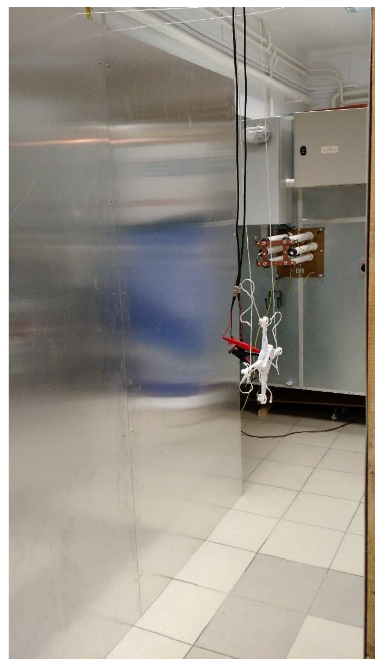
At the beginning of tests, the unmanned aerial vehicle was suspended in the middle between two plates as parallel as possible to them, hanging on two strings to reflect the actual position of the unmanned aerial vehicle during a flight, relative to the clouds.
Figure 5 presents photography of the described setup (for first tests, using a smaller UAV).
Based on the above-mentioned literature, it was estimated that the simulated distances between the CG channel and the flying drone were, respectively, for the WF4 at a few hundred meters (400 m to 1000 m), while for VW 1.2/50 μs the distance would be in the range of 100 m–500 m [
32,
33].
The choice of the voltage waveform parameters, both in terms of amplitude and characteristic times, was not accidental. Their parameters corresponded to the distance of the drone from the lightning discharge channel, as evidenced by numerous measurements and simulations of the developed mathematical models [
34,
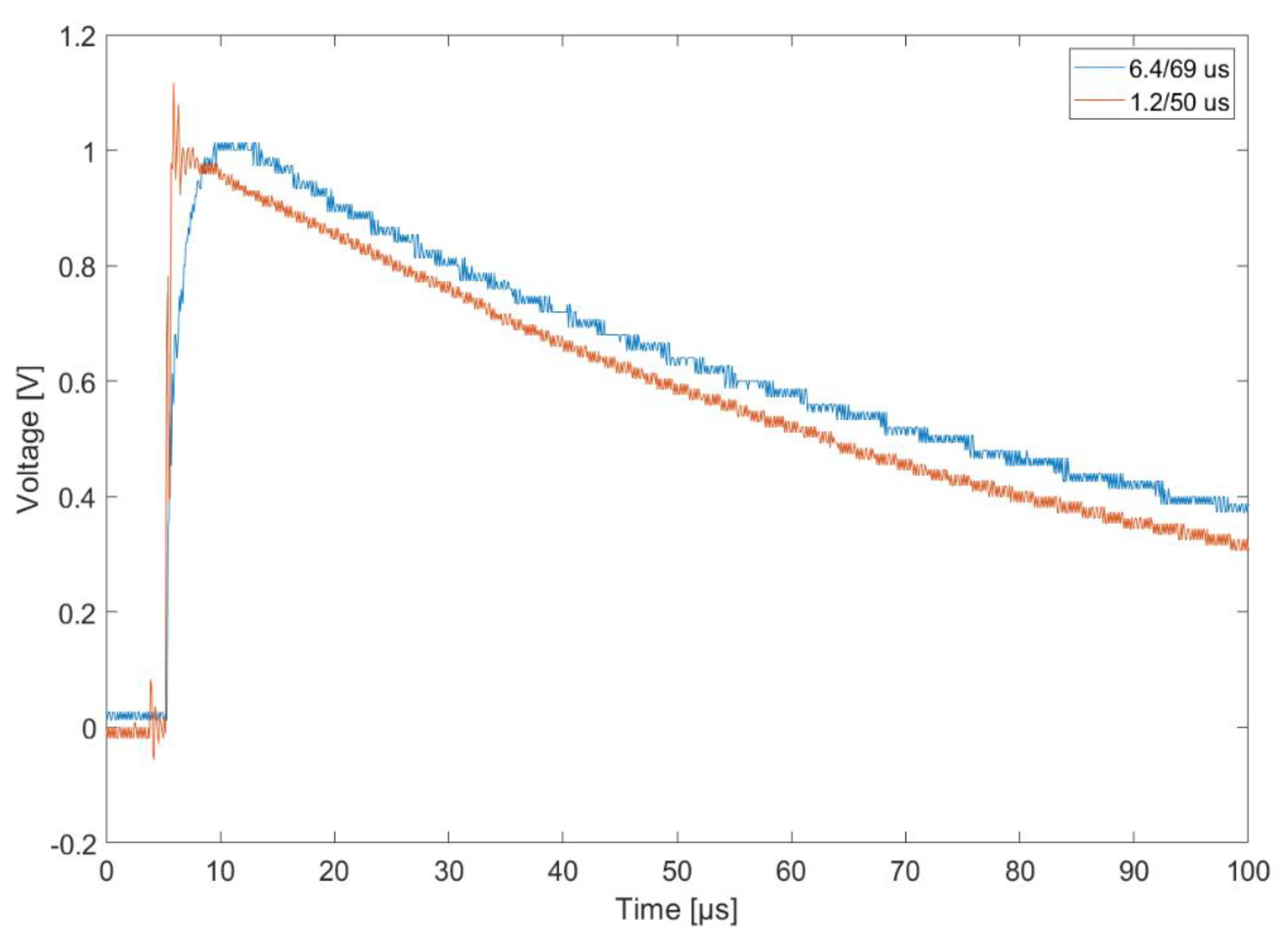
35]. Measured signals form generators was shown in
Figure 6.
4. Forming Element for Marx Generator
While the shape and characteristic times of the pulses from the MIG 0618SS generator are imposed, and any changes can be made only through the control panel, and within the scope provided by the manufacturer, the pulse from the Marx generator can be freely formed by changing the parameters of the forming system connected to its output terminals [
9,
13,
36]. The VW 1.2/50 pulse generator consists of the components shown in
Figure 1. An autotransformer on the low-voltage side was used to regulate the voltage. The voltage was then stepped up using an LV/HV transformer and rectified. Another component was a three-stage Marx generator with capacitors with a total capacity of 0.133 μF during discharge (series connection). The key element determining the characteristic times of the output pulse was the designed and manufactured forming circuit. It consisted of properly selected and interconnected resistors and capacitances, forming the pulse. After estimating the parameters of the forming circuit, its operation was simulated in the Micro-Cap 12 program to verify the correctness of the calculations. The simulation’s results were satisfactory, so it was decided to build a physical circuit and then test it. The output parameters of the pulse from the physical system did not deviate significantly from the results obtained during simulation and were within the range predicted by the PN-EN 61000-4-5:2014-10 standard. The use of simulation tools simplified the construction of the physical forming system necessary to provide a 1.2/50 μs pulse.
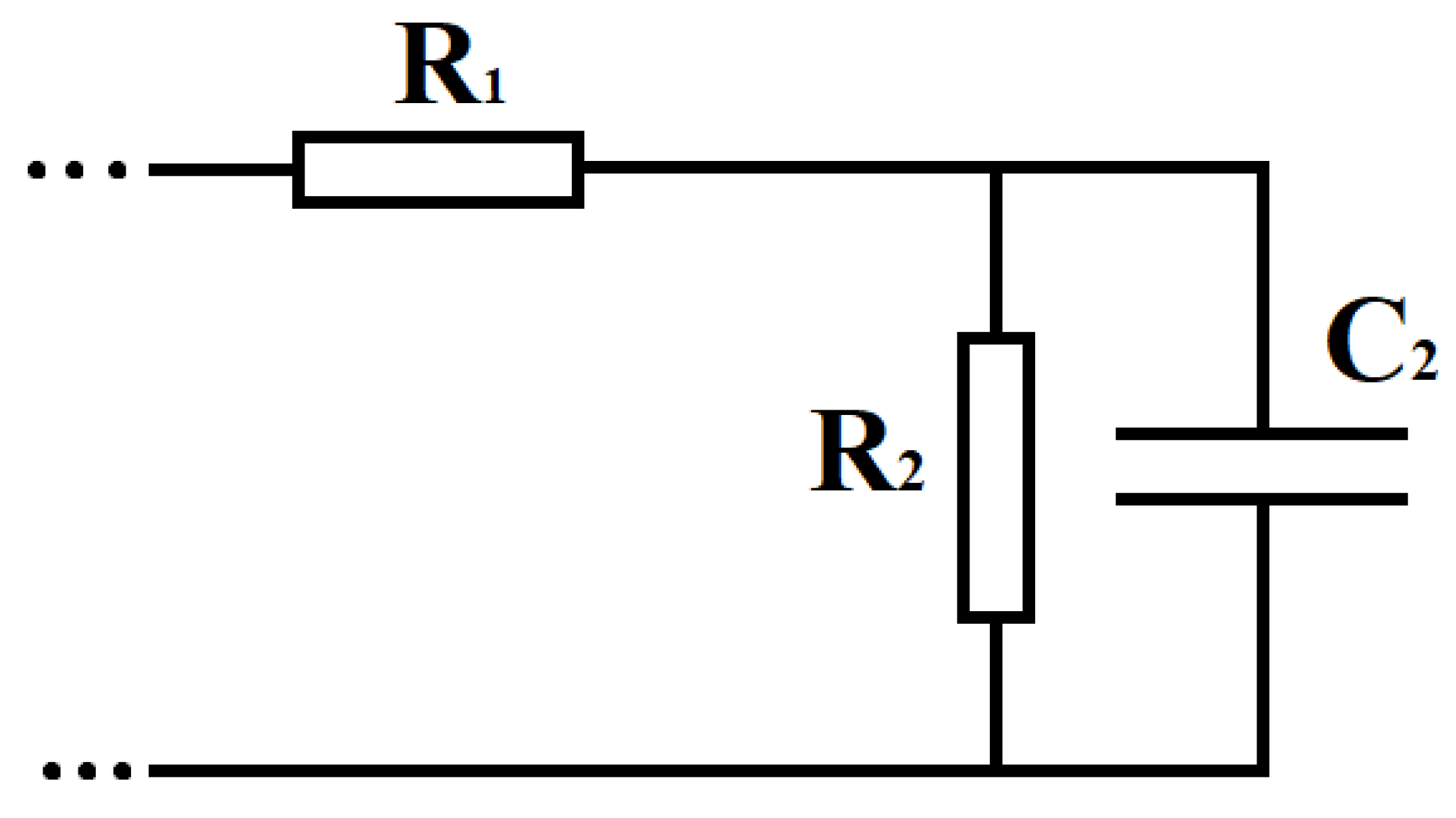
The parameters of the forming system had been calculated so that the output pulse met the required characteristic time values. It was decided that the forming circuit would be connected in an “a” shape (
Figure 7)—part of the whole system presented in
Figure 1 [
9,
13].
Using the Laplace transform, the impedance of the circuit is
The current flowing through the generator in Laplace form is given by the equation
The voltage
V(
s) is therefore
In the end, the voltage
V(
s) can be expressed as
where:
Taking the inverse Laplace transform of the Equation (7),
The rising time
t1 is given by equation
If
β > (2/
t1)
α-
β can be given by equation
where
Assuming that
α =
β, Equation (11) takes the form
Using Equations (12) and (14), approximate values of α and β can be obtained.
These parameters are needed to determine the resistances
R1 and
R2 from equations
and
Results: the value of elements from
Figure 7 were equal to (as shown in scheme in
Figure 2):
- ▪
R1 = 91 Ω
- ▪
R2 = 491 Ω
- ▪
C2 = 2.5 nF
5. The Key Elements Response
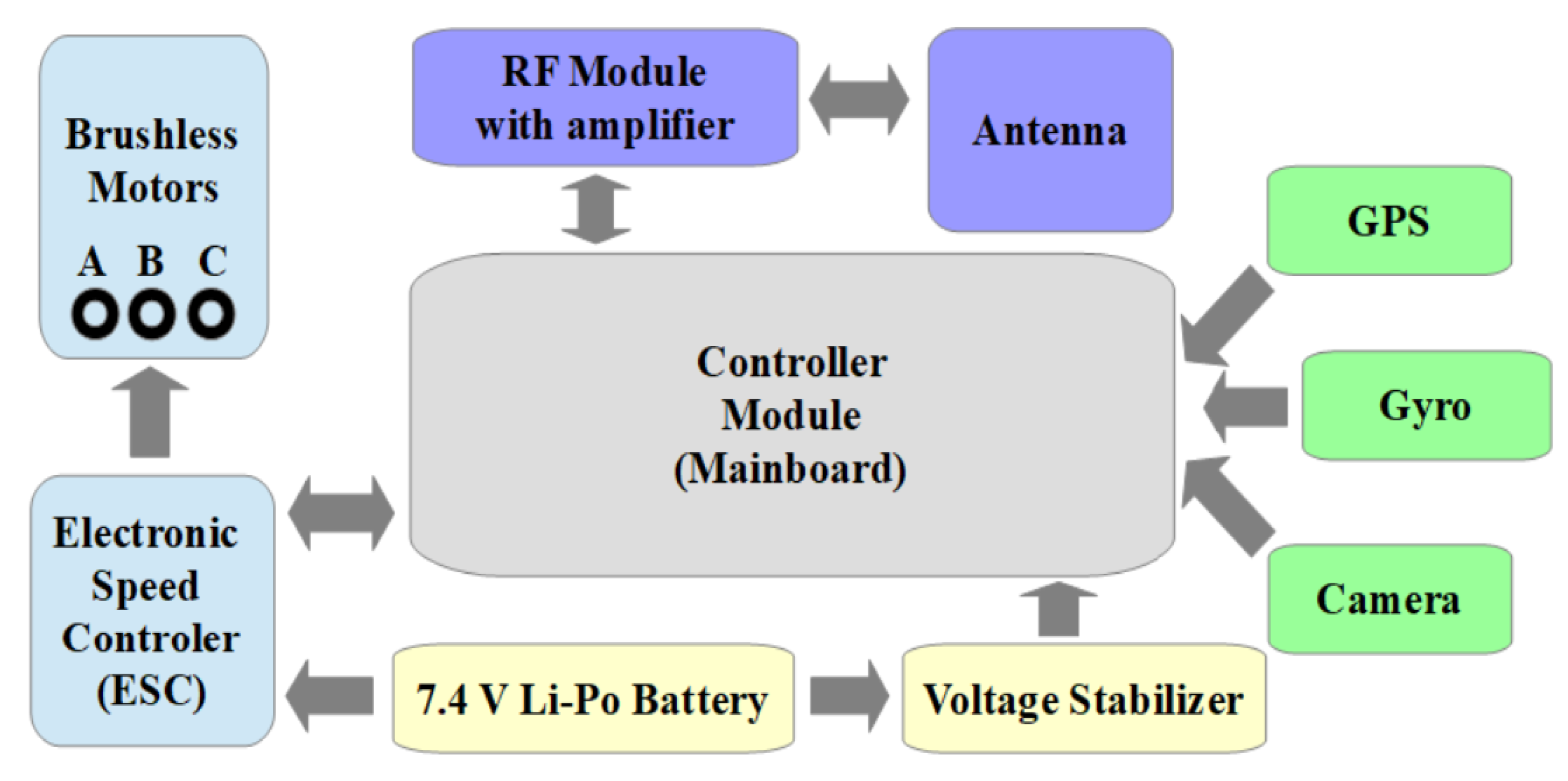
During the tests, the focus was on the basic elements of the drone, which occur in all unmanned aerial vehicles. Those parts (typical UAV construction) are presented in
Figure 8.
The elements from which the signal was collected (during exposure) were:
- (a)
Motor winding,
- (b)
Electronic speed controller (ESC),
- (c)
Li-Ion battery,
- (d)
Voltage stabilizer,
- (e)
Radio frequency module,
- (f)
GPS module,
- (g)
Path between motor and antenna output.
The induced voltage was collected via BNC cables directly to the oscilloscope, which allowed for the ongoing observation of the results. The drones had been properly prepared—terminals had been taken out of selected elements to facilitate the connection of measuring cables and ensure the stability of this connection during measurements. The oscilloscope to which the BNC cables were connected had two inputs, with an input impedance of 1 MΩ. Next, the results were saved in *.CSV files and further analyzed. The results are presented in the figures below.
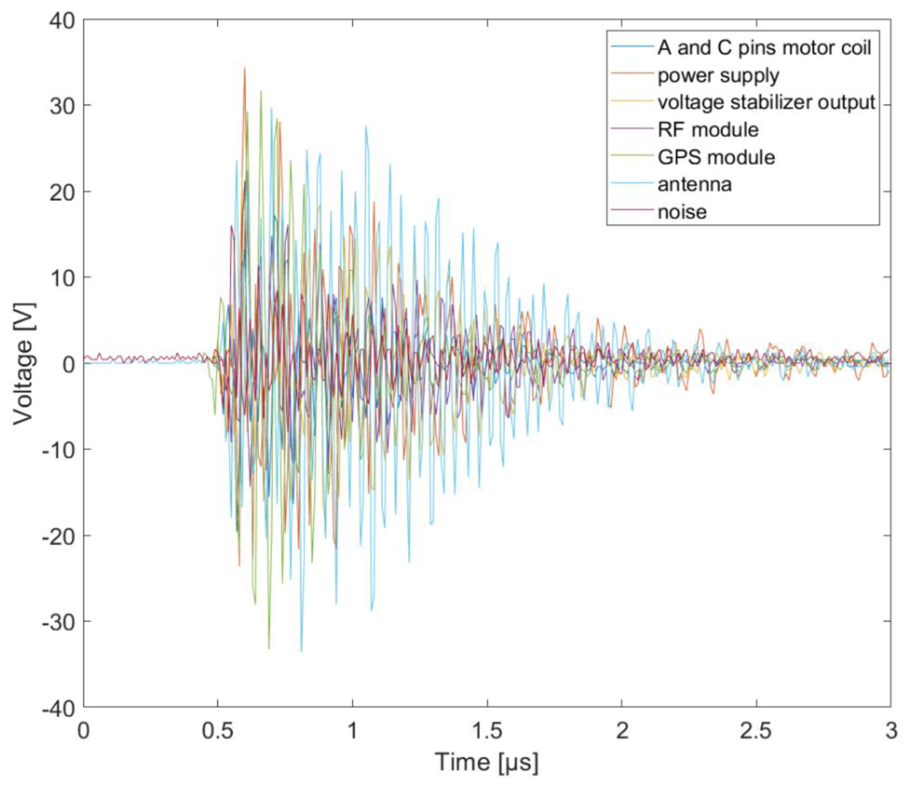
Figure 9 and
Figure 10 show overvoltage in different parts of a UAV (the second drone, because the first, smaller one, unfortunately was damaged) for both surge impulse shapes. The shapes of the overvoltage are similar, but amplitudes are different, especially for higher voltages (
Figure 11).
Figure 9 shows that the greatest voltage was induced in the antenna circuit. The next-most critical elements are the RF module and the GPS module. As one can see, the frequencies of the overvoltage in all of the circuits’ parts were different for both surge pulses (6.4/69 μs and 1.2/50 μs). The responses (each one separate) on the different harmonic components of the pulse were dependent on the resonance frequencies.
An increase in voltage above a specific range in those elements may lead to their faulty operation or, in extreme cases—damage.
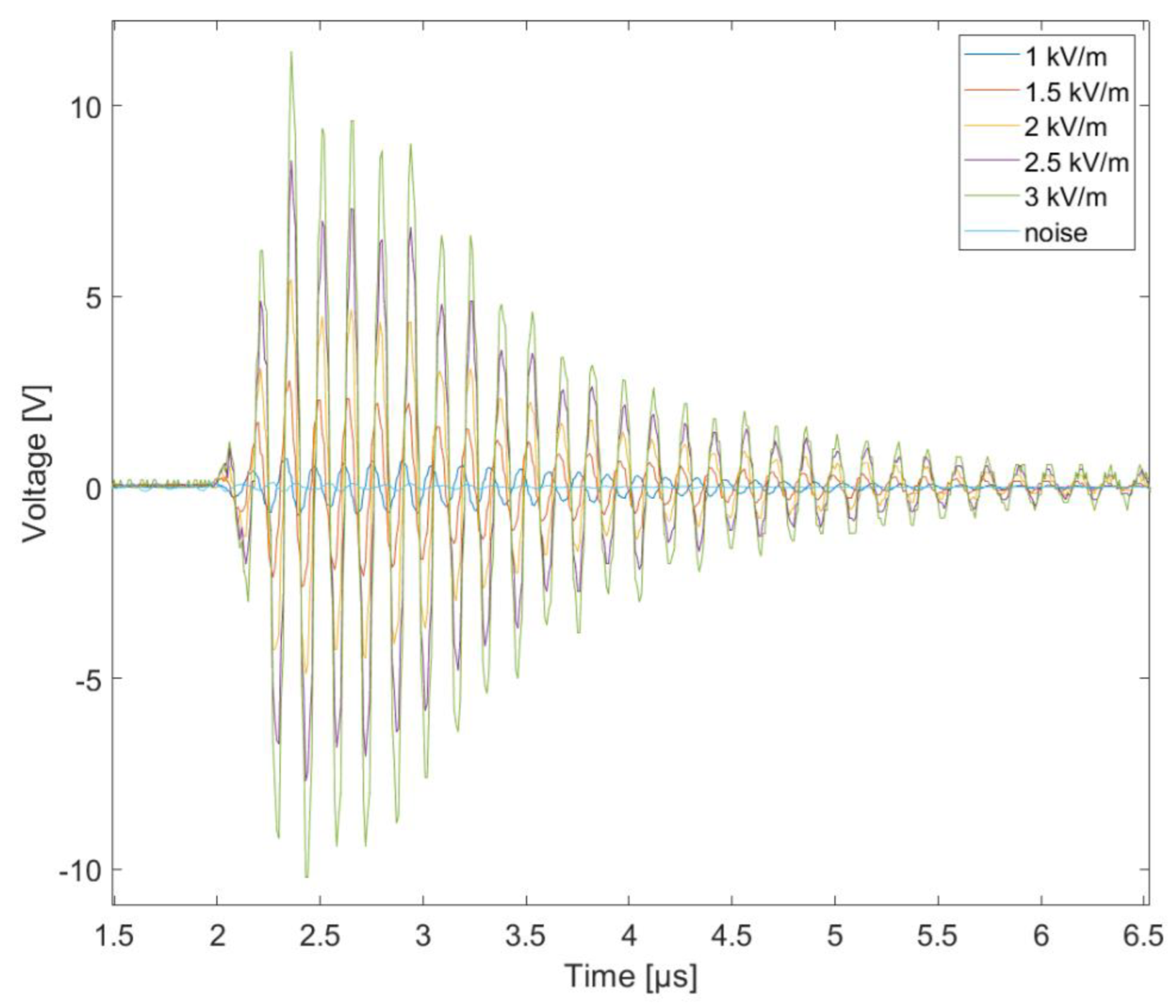
Figure 12 and
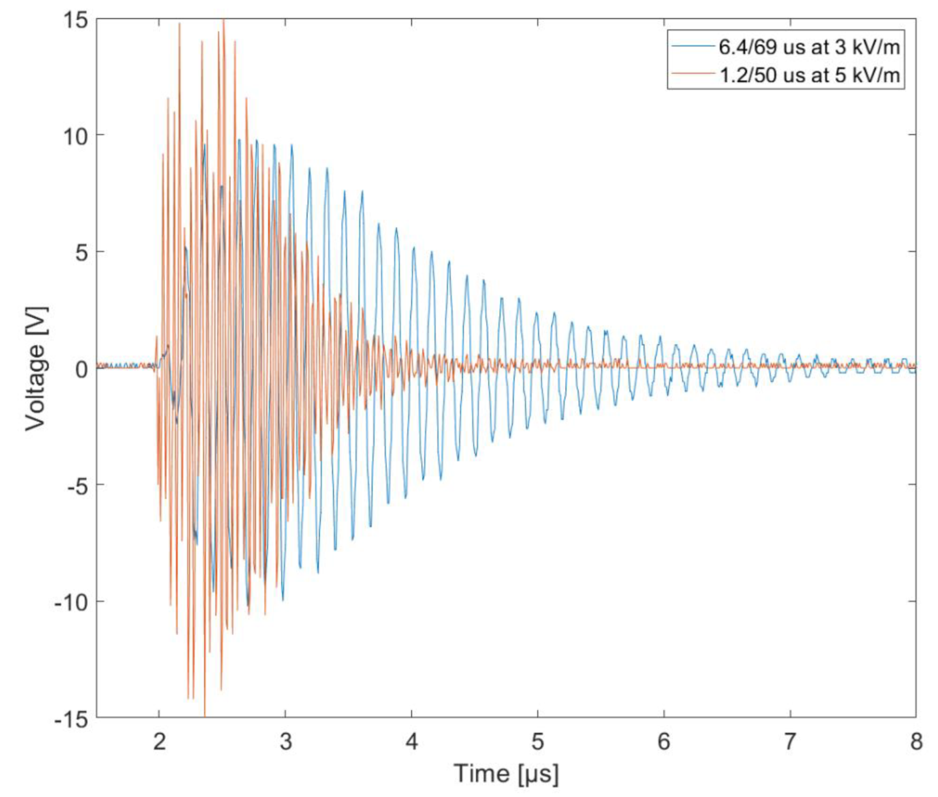
Figure 13 show that the induced voltage amplitude on an RF antenna increases linearly with the increase of the electric field’s component strength, which simulates a closer and closer distance from the signal source, which is the CG flash. The responses of the tested electronic parts to the VW pulse was shorter than in the case of WF4 (
Figure 14). This is due to the rising time of those impulses (all responses of the systems were observed at the rising edge of the impulse).
A short stroke duration means a high frequency. Circuits of longer lengths (paths in PCB, coils, etc.) are sensitive to this. Static electric fields don’t induce any disturbances that could damage the drone.
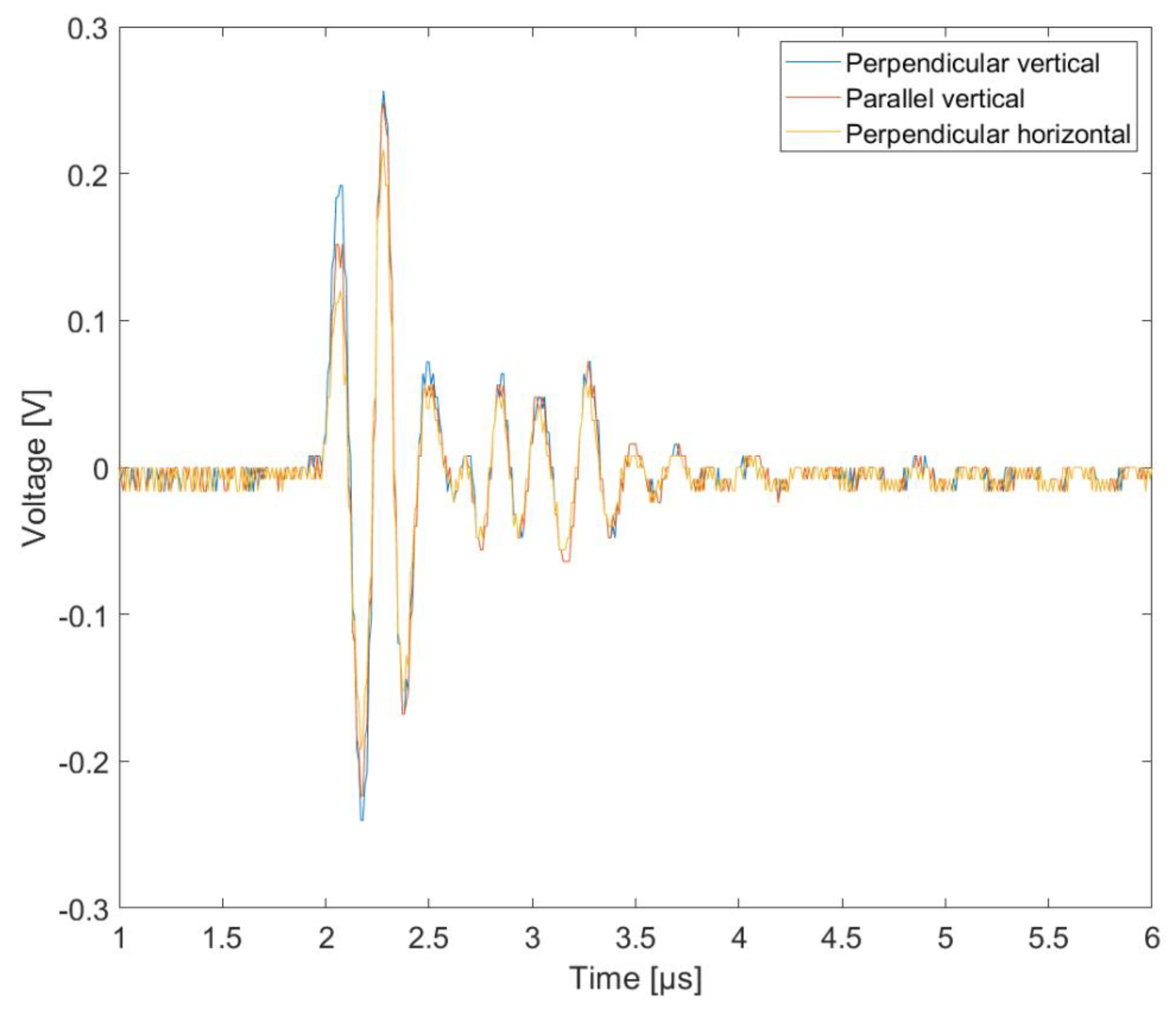
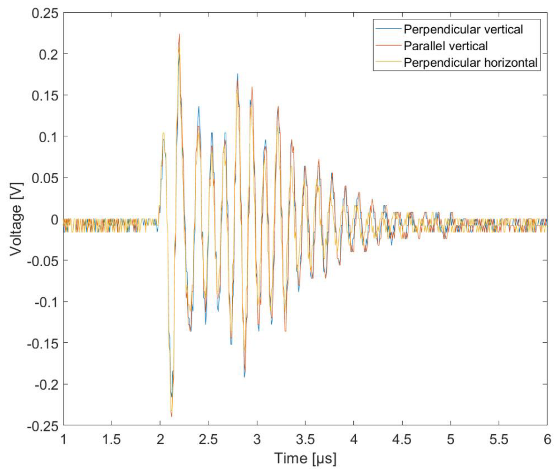
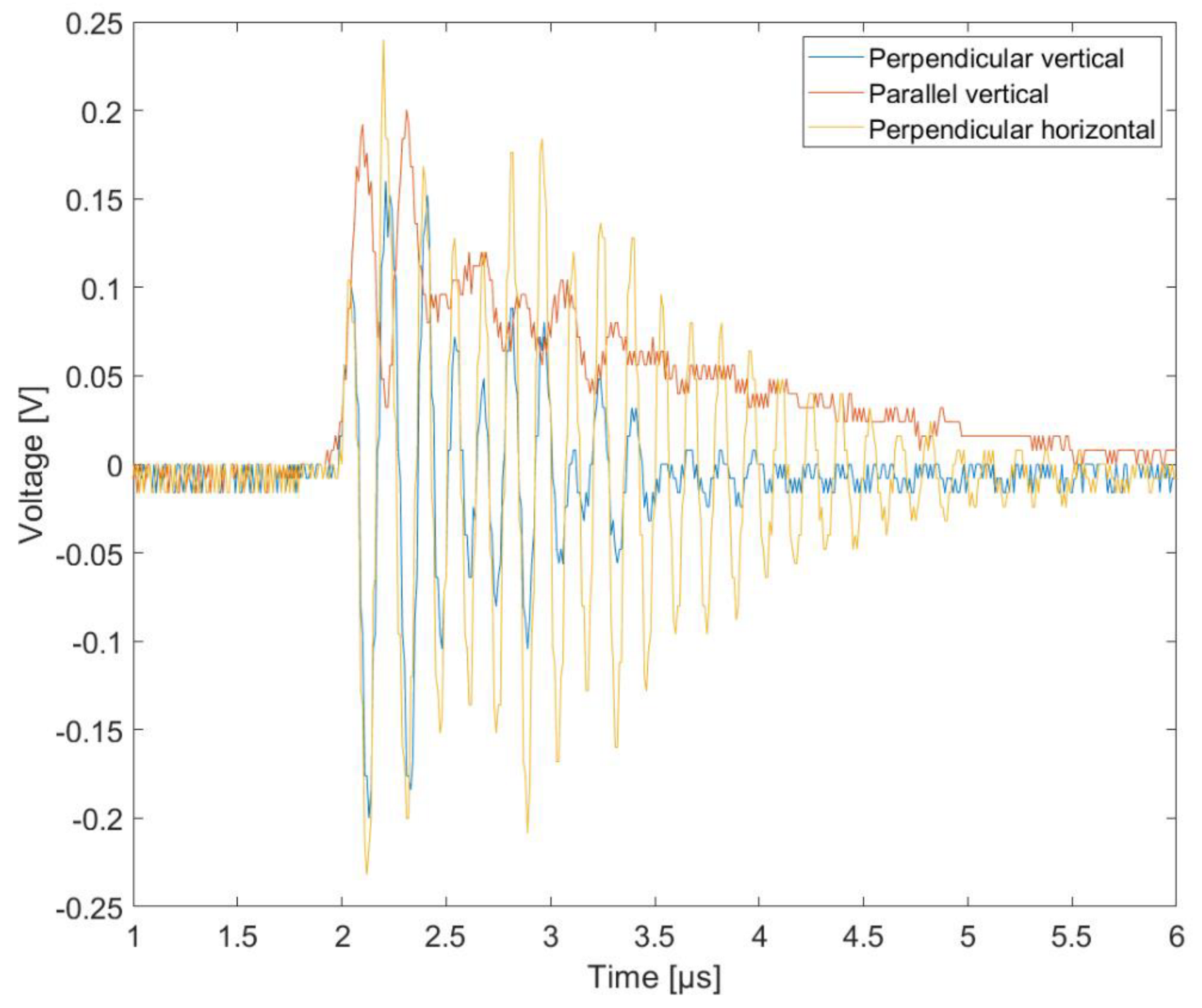
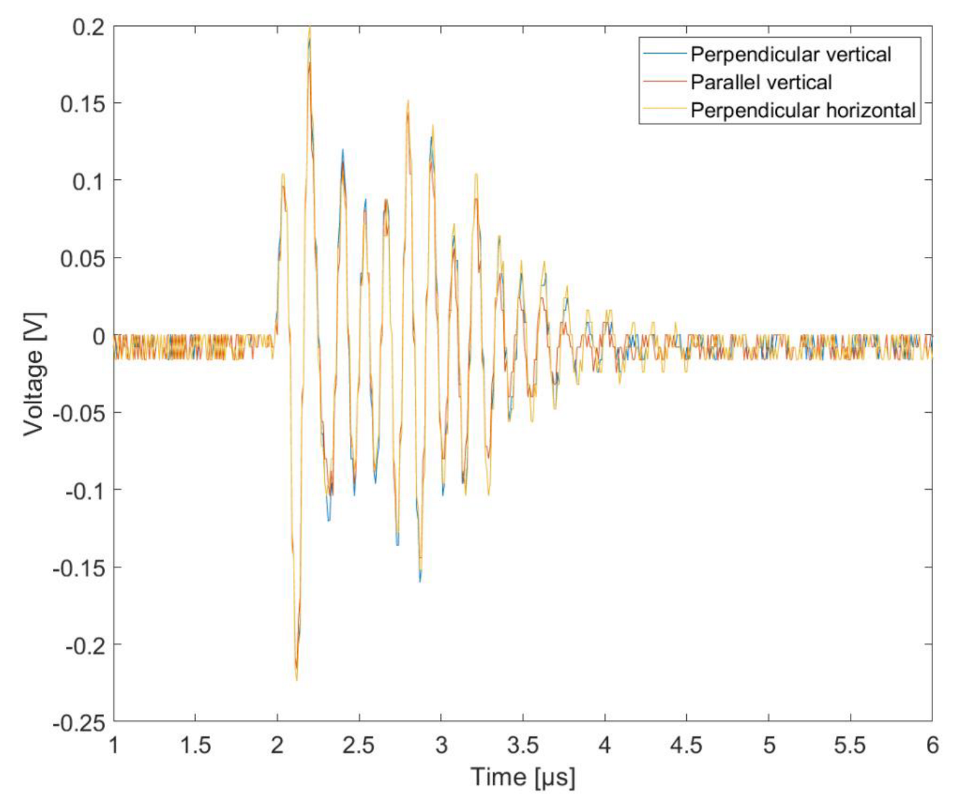
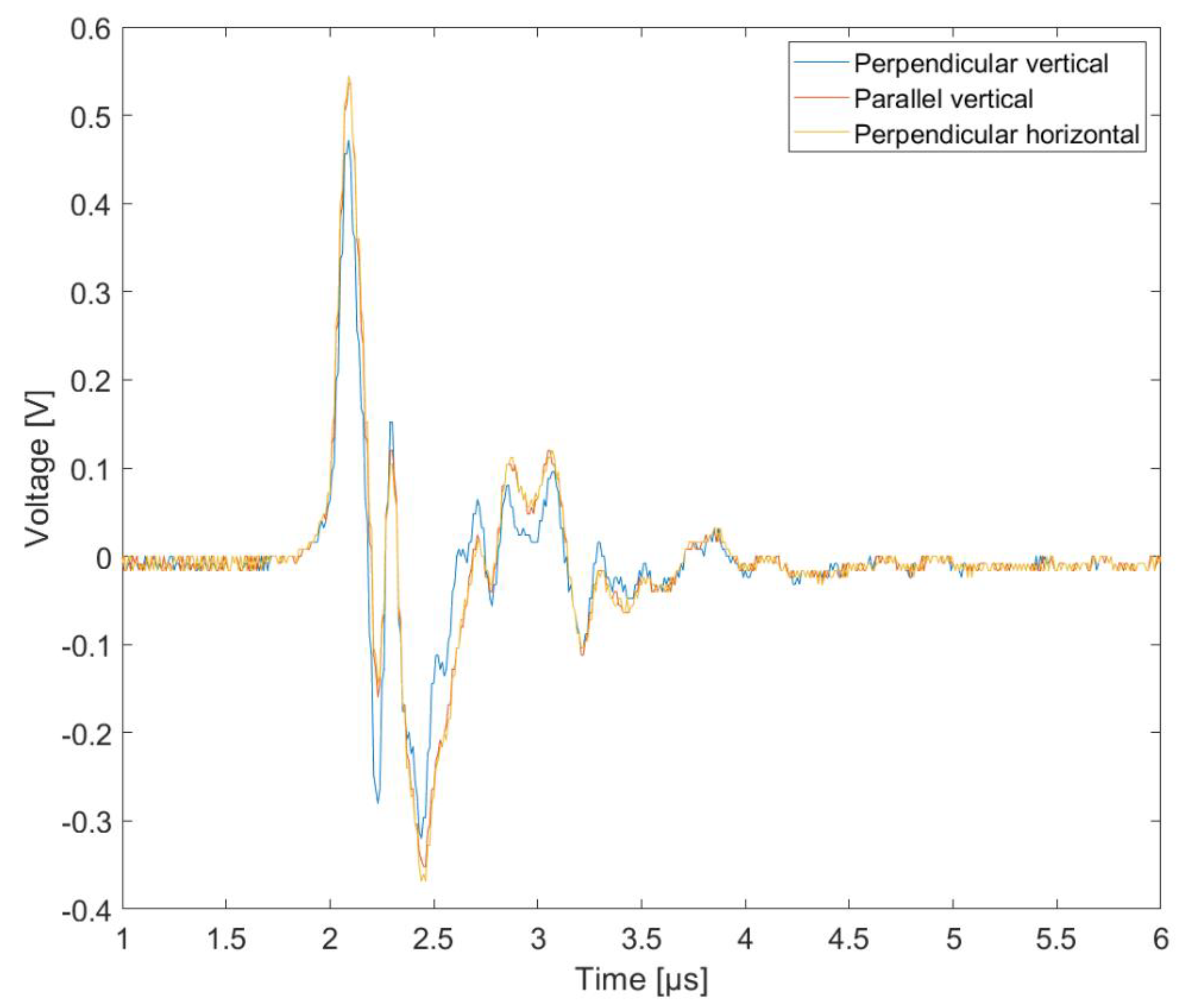
The next step was to check how the size of the induced voltage in individual selected elements (circuits) depended on the position of the drone in relation to the capacitor plates (relative to the electric field line). Three positions were tested:
- (a)
Perpendicular vertical,
- (b)
Perpendicular horizontal,
- (c)
Parallel vertical.
Among the tested elements, only in the case of the antenna was the position of the drone in relation to the capacitor plates of great importance. No significant changes were observed to the remaining tested elements.
6. Conclusions
The primary objective of this research was to determine the effect of the electrical component accompanying lightning on the operation of unmanned aerial vehicles. The study of the resilience of such machines is crucial for their increasingly widespread use, which involves operation in a variety of conditions. With the use of generators designed to test the resistance of aircraft avionics to lightning in accordance with the RTCA DO-160 standard, it is possible to show the real surges that occur in the electronics circuits of a drone, as if it were being studied in the manner of an aircraft. The results of exposure tests of commercial unmanned aircraft confirm the relatively high resistance of electronic components to disturbances from the electrical component (i.e., surges below supply voltages, and of very short duration). This result is not surprising, given the small size of the object, which translates into low levels of induced voltage. We can therefore say that this component is relatively safe and does not affect the operation of the device. Much more dangerous for the tested elements is the magnetic component of the proximity discharge, causing the induction of much higher voltages compared to the exposure of the electrical component (as presented in another paper). The key factor here is the distance and the current in the lightning channel.
Due to the presence of semiconductor components and integrated circuits, the polarity of the discharge also has a huge impact on the propagation of the disturbance through the various components of the drone’s electronics, which are most sensitive to it.
Most of the tested electronic components of the drone are galvanically connected with each other and form a single, complex circuit with low impedance. The components most sensitive to electromagnetic radiation are the active electronic systems, such as the antenna amplifier, and the semiconductor elements.
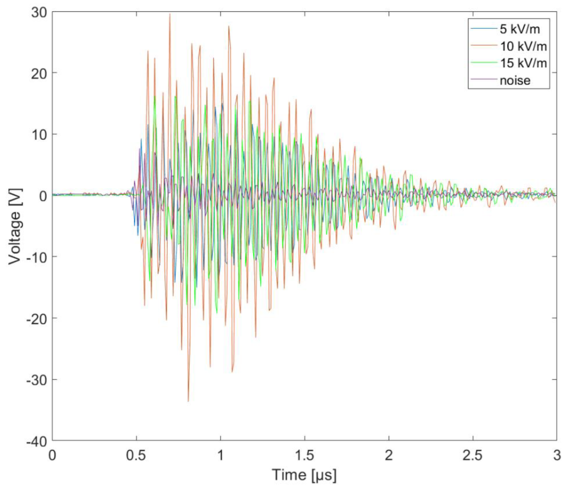
Comparing the values of the induced voltages presented in
Figure 10 and
Figure 11, it can be seen that, for 5 kV/m and 10 kV/m, overvoltages are two times higher. For the tests over 15 kV/m, the results do not vary in a linear manner as previously. Presumably, this is caused by damage to some parts of the tested electronics during measurements at an electric field strength of 15 kV/m. After these measurements, the device did not work properly. This means that the resulting surges damaged the integrated circuits.
The change in overvoltages in the drone’s circuits increases linearly with the electric field’s strength. This allows the scaling of possible values during a discharge of a few megavolts at a short distance. Of course, this voltage value would be in the lightning channel. The voltage as a function of the distance (V/m) could have a completely different value, and much smaller, so the overvoltages in the drone will not be that high.
In most cases considered, the position of the drone in relation to the electrically charged plates was not important, but this was not the case for the antenna system. In further research, it is not necessary to analyze the position of the machine in relation to the capacitor facings (simulating the cloud-ground system).
A summary of the presented results can be set forth as follows:
- ▪
There is no relation between position of the UAV (orientation) and overvoltage value,
- ▪
There is a linear dependence between level of electric field and drone overvoltage,
- ▪
The most resistance to damage is found in the motors and batteries,
- ▪
The components most sensitive to overvoltage are the antennas and semiconductor units,
- ▪
Short impulses with overvoltage ranges around the power supply value are not dangerous for UAV functionality.
Based on the study, it can be concluded that lightning discharges at a distance of more than 1 km from a flying commercial drone carry a negligible risk of damage to it (taking into account the average values of lightning currents). Note, however, that only one component of the electromagnetic field is presented here, showing its impact independently. When a drone is exposed to a LEMP, the impact will be greater, as the impacts will amplify each other.
Author Contributions
Conceptualization, P.S. and T.K.; data curation, P.S. and T.K.; formal analysis, P.S. and T.K.; methodology, P.S. and T.K.; project administration, P.S.; resources, P.S. and T.K.; software, P.S. and T.K.; visualization, T.K.; writing—original draft, P.S. and T.K.; writing—review and editing, P.S. and T.K. All authors have read and agreed to the published version of the manuscript.
Funding
Ministry of Science and Higher Education of the Republic of Poland: Maintain the research potential of the discipline of automation, electronics, electrical engineering and space technologies.
Data Availability Statement
Not applicable.
Conflicts of Interest
The authors declare no conflict of interest.
References
- Divya, J. Exploring the Latest Drone Technology for Commercial, Industrial and Military Drone Uses. 2017. Available online: https://www.businessinsider.com/drone-technology-uses-2017-7?IR=T (accessed on 15 May 2023).
- Maslowski, G.; Rakov, V.A. New Insights into Lightning Return-Stroke Models with Specified Longitudinal Current Distribution. IEEE Trans. Electromagn. Compat. 2009, 51, 471–478. [Google Scholar] [CrossRef] [Green Version]
- Cooray, V. An Introduction to Lightning; Springer: Berlin/Heidelberg, Germany, 2015; Volume 201. [Google Scholar]
- Kossowski, T.; Kamil, F. Lightning tests of unmanned aircrafts with impulse generator. Prz. Elektrotechniczny 2020, 96, 67–70. [Google Scholar] [CrossRef]
- Barr, L.C.; Newman, R.; Ancel, E.; Belcastro, C.M.; Foster, J.V.; Evans, J.; Klyde, D.H. Preliminary Risk Assessment for Small Unmanned Aircraft Systems. In Proceedings of the 17th AIAA Aviation Technology, Integration, and Operations Conference, Denver, CO, USA, 5–9 June 2017. [Google Scholar]
- Masłowski, G. Analiza i Modelowanie Wyładowań Atmosferycznych na Potrzeby Ochrony Przed Przepięciami; Monografia; Wydawnictwa AGH: Kraków, Poland, 2010. [Google Scholar]
- PN-EN 62305-1:2011; Lightning Protection—Part 1. BSI Standards Publication: London, UK, 2011.
- PN-EN 61000-4-5:2014-10; Electromagnetic Compability (EMC)—Part 4–5: Methods of Research and Measurement—Shock Resistance Test. PKN: Warszawie, Poland, 2014.
- RTCA DO-160; Environmental Conditions and Test Procedures for Airborne Equipment. Radio Technical Commission for Aeronautics: Washington, DC, USA, 2010.
- Lin, T.; Uman, M.A.; Tiller, J.A.; Brantley, R.D.; Krider, E.P.; Weidman, C.D. Characteryzation of lightning return stroke electric and magnetic fiels form simultaneous two-station measurements. J. Geophys. Res. 1979, 84, 6307–6314. [Google Scholar] [CrossRef]
- Karnas, G.; Barański, P.; Masłowski, G. A New Method for Modeling and Parameter Identification of Positively Charged Downward Lightning Leader Based on Remote Lightning Electric Field Signatures Recorded in the ELF/MF Range and 3D Doppler Radar Scanning Data. Energies 2022, 15, 8566. [Google Scholar] [CrossRef]
- Filik, K. Badanie odporności zespołów awioniki statków powietrznych na narażenia LEMP. Prz. Elektrotechniczny 2014, 10, 60–63. [Google Scholar]
- Kossowski, T.; Szczupak, P. Analysis of the influence of strong magnetic field on unmanned aircrafts, using Helmholtz coil. Prz. Elektrotechniczny 2020, 96, 11–14. [Google Scholar] [CrossRef]
- Hu, J.; Zhu, T.; Hu, J.; Fang, Z.; Zhang, R. Study on the Lightning Protection Performance for a 110 kV Non-Shield-Wired Overhead Line with Anti-Thunder and Anti-Icing Composite Insulators. Energies 2023, 16, 815. [Google Scholar] [CrossRef]
- Gaynutdinov, R.R.; Chermoshentsev, S.F. Study of Lightning Strike Impact on Unmanned Aerial Vehicle. In Proceedings of the 2016 17th International Conference of Young Specialists on Micro/Nanotechnologies and Electron Devices (EDM), Erlagol, Russia, 30 June–4 July 2016; pp. 428–432. [Google Scholar] [CrossRef]
- Lin, Z.; Lin, M.; Champagne, B.; Zhu, W.-P.; Al-Dhahir, N. Secrecy-Energy Efficient Hybrid Beamforming for Satellite-Terrestrial Integrated Networks. IEEE Trans. Commun. 2021, 69, 6345–6360. [Google Scholar] [CrossRef]
- Lin, Z.; Lin, M.; de Cola, T.; Wang, J.-B.; Zhu, W.-P.; Cheng, J. Supporting IoT with Rate-Splitting Multiple Access in Satellite and Aerial-Integrated Networks. IEEE Internet Things J. 2021, 8, 11123–11134. [Google Scholar] [CrossRef]
- Lin, Z.; Lin, M.; Huang, Y.; de Cola, T.; Zhu, W.-P. Robust Multi-Objective Beamforming for Integrated Satellite and High Altitude Platform Network With Imperfect Channel State Information. IEEE Trans. Signal Process. 2019, 67, 6384–6396. [Google Scholar] [CrossRef]
- Rakov, V.A.; Uman, M.A. Lightning Physics and Effects; Cambridge University Press: Cambridge, UK, 2003. [Google Scholar]
- MIL-STD-461F; Department of Defense Interface Standard Requirements for the Control of Electromagnetic Interference Characteristics of Subsystems and Equipment. The United States Department of Defense: Arlington County, VA, USA, 2007.
- Aircraft Lightning Environment and Related Test Waveforms; Revision A; SAE International: Warrendale, PA, USA, 2005.
- Sehrawat, A.T.; Anupriya, C.; Gaurav, R. Surveillance Drone for Disaster Management and Military Security. In Proceedings of the 2017 International Conference on Computing, Communication and Automation (ICCCA), Greater Noida, India, 5–6 May 2017; IEEE: New York, NY, USA, 2017. [Google Scholar]
- Hacker, P.T.; Plumer, J.A. Measurements and Analysis of Lightning-Induced Voltages in Aircraft Electrical Circuits. In SAE Trans.; 1970; pp. 2735–2752. Available online: https://ntrs.nasa.gov/api/citations/19710009647/downloads/19710009647.pdf (accessed on 15 May 2023).
- Shoory, A.; Rachidi, F.; Rubinstein, M.; Thottappillil, R. On the Measurement and Calculation of Horizontal Electric Fields from Lightning. IEEE Trans. Electromagn. Compat. 2011, 53, 792–801. [Google Scholar] [CrossRef]
- Baba, Y.; Rakov, V.A. Electromagnetic Fields at the Top of a Tall Building Associated with Nearby Lightning Return Strokes. IEEE Trans. Electromagn. Compat. 2007, 49, 632–643. [Google Scholar] [CrossRef] [Green Version]
- Fernando, M.; Cooray, V. Propagation effects on the electric field time derivatives generated by return strokes in lightning flashes. J. Atmos. Sol. Terr. Phys. 2007, 69, 1388–1396. [Google Scholar] [CrossRef]
- Zhou, Q.; Shi, Y.; Bian, X.; Zhou, B. Simulation and Protection of Lightning Electromagnetic Pulse in Non-Metallic Nacelle of Wind Turbine. Energies 2019, 12, 1745. [Google Scholar] [CrossRef] [Green Version]
- Qu, L.; Wang, Y.; Liu, G.; Liao, M.; Cai, H.; Zhang, T.; Deng, Y.; Wen, X. Simulation Study on Positive Corona Discharge of Receptors on Rotating Wind Turbine Blade Tips under Thundercloud Electric Fields. Energies 2019, 12, 4696. [Google Scholar] [CrossRef] [Green Version]
- Kisielewicz, T.; Piparo, G.B.L.; Mazzetti, C. Frequency of Damage of Low Voltage Apparatus Due to Lightning Flashes to Ground Nearby HV Overhead Lines. Energies 2022, 15, 7809. [Google Scholar] [CrossRef]
- Barradas, R.P.d.S.; Rocha, G.V.S.; Muniz, J.R.S.; Bezerra, U.H.; Nunes, M.V.A.; e Silva, J.S. Methodology for Analysis of Electric Distribution Network Criticality Due to Direct Lightning Discharges. Energies 2020, 13, 1580. [Google Scholar] [CrossRef] [Green Version]
- NO-16-A002:2006; Ochrona Przed Skutkami Wyładowania Atmosferycznego. Wymagania Ogólne. Decision No. 308/MON of the Minister of National Defense of the Republic of Poland of 23 June 2006; Ministry of National Defence: Warsaw, Poland, 2006.
- Gaynutdinov, R.R.; Chermoshentsev, S.F. Study of Impact Lightning at of Electromagnetic and Thermal Stability of Fuselage of Unmanned Aerial Vehicle. In Proceedings of the 2016 International Conference on Actual Problems of Electron Devices Engineering (APEDE), Saratov, Russia, 22–23 September 2016; pp. 1–6. [Google Scholar] [CrossRef]
- Luo, D.; Cao, Y.; Zhang, Y.; Xie, S.; Zhang, C.; Cao, S. Study on Structural Parameters and Analysis Method of Soil Successive Impulse Discharge Channel. Energies 2021, 14, 877. [Google Scholar] [CrossRef]
- Tarko, R.; Gajdzica, J.; Nowak, W.; Szpyra, W. Study of the Lightning Overvoltage Protection Effectiveness of High Voltage Mixed Overhead Cable Power Lines. Energies 2021, 14, 2329. [Google Scholar] [CrossRef]
- Environmental Conditions and Test Procedures for Aircraft Systems; Federal Aviation Administration: Washington, DC, USA, 2006.
- Fisher, F.A.; Plumer, J.A.; Perala, R.A. Aircraft Lightning Protection Handbook; DOT/FAA/CT-89/22; Federal Aviation Administration: Washington, DC, USA, 1989. [Google Scholar]
Figure 1.
The vertical component of the lightning electric field for different distances from the discharge channel, and the typical current for the next negative main discharge.
Figure 1.
The vertical component of the lightning electric field for different distances from the discharge channel, and the typical current for the next negative main discharge.
Figure 2.
Setup for the lightning electric field simulation.
Figure 2.
Setup for the lightning electric field simulation.
Figure 3.
Waveform 4–Voltage double exponential 6.4 μs (T1)/69 μs (T2) [
3,
4,
20].
Figure 3.
Waveform 4–Voltage double exponential 6.4 μs (T1)/69 μs (T2) [
3,
4,
20].
Figure 4.
Voltage waveform, where T1 = 1.2 μs, and T2 = 50 μs [
3,
4,
20].
Figure 4.
Voltage waveform, where T1 = 1.2 μs, and T2 = 50 μs [
3,
4,
20].
Figure 5.
Photography of tested UAV.
Figure 5.
Photography of tested UAV.
Figure 6.
Surge pulse shapes: (1) WaveForm 4–6.4/69 μs and (2) voltage waveform–1.2/50 μs.
Figure 6.
Surge pulse shapes: (1) WaveForm 4–6.4/69 μs and (2) voltage waveform–1.2/50 μs.
Figure 7.
Pulse forming an “a” shape circuit.
Figure 7.
Pulse forming an “a” shape circuit.
Figure 8.
Common parts of all types of drones.
Figure 8.
Common parts of all types of drones.
Figure 9.
Overvoltage on second drone’s circuits under electric field. Efield = 1 kV/m for WF4 waveform (6.4/69 μs).
Figure 9.
Overvoltage on second drone’s circuits under electric field. Efield = 1 kV/m for WF4 waveform (6.4/69 μs).
Figure 10.
Drone circuits’ response under 5 kV/m 1.2/50 μs pulsed electric field.
Figure 10.
Drone circuits’ response under 5 kV/m 1.2/50 μs pulsed electric field.
Figure 11.
Drone circuits response under 10 kV/m 1.2/50 μs pulsed electric field.
Figure 11.
Drone circuits response under 10 kV/m 1.2/50 μs pulsed electric field.
Figure 12.
Overvoltage between RF antenna and GND for several examples of electric pulse field strength (WF4).
Figure 12.
Overvoltage between RF antenna and GND for several examples of electric pulse field strength (WF4).
Figure 13.
Overvoltage RF–GND, 1.2/50 μs, negative polarity.
Figure 13.
Overvoltage RF–GND, 1.2/50 μs, negative polarity.
Figure 14.
Overvoltage between RF antenna and GND for 6.4/69 μs and 1.2/50 μs waveforms.
Figure 14.
Overvoltage between RF antenna and GND for 6.4/69 μs and 1.2/50 μs waveforms.
Figure 15.
Overvoltage between RF antenna and GND for 6.4/69 μs and 1.2/50 μs waveforms.
Figure 15.
Overvoltage between RF antenna and GND for 6.4/69 μs and 1.2/50 μs waveforms.
Figure 16.
Overvoltage in drone voltage stabilizer dependent on its position related to plates.
Figure 16.
Overvoltage in drone voltage stabilizer dependent on its position related to plates.
Figure 17.
Overvoltage in drone RF antenna dependent on its position related to plates.
Figure 17.
Overvoltage in drone RF antenna dependent on its position related to plates.
Figure 18.
Overvoltage in drone ESC supply dependent on its position related to plates.
Figure 18.
Overvoltage in drone ESC supply dependent on its position related to plates.
Figure 19.
Overvoltage in one of the drone motor coils, dependent on its position related to plates.
Figure 19.
Overvoltage in one of the drone motor coils, dependent on its position related to plates.
| Disclaimer/Publisher’s Note: The statements, opinions and data contained in all publications are solely those of the individual author(s) and contributor(s) and not of MDPI and/or the editor(s). MDPI and/or the editor(s) disclaim responsibility for any injury to people or property resulting from any ideas, methods, instructions or products referred to in the content. |
© 2023 by the authors. Licensee MDPI, Basel, Switzerland. This article is an open access article distributed under the terms and conditions of the Creative Commons Attribution (CC BY) license (https://creativecommons.org/licenses/by/4.0/).


