Article

Principle and Feasibility Study of Proposed Hydrate-Based Cyclopentane Purification Technology

1
Key Laboratory of Ocean Energy Utilization and Energy Conservation of Ministry of Education, School of Energy & Power Engineering, Dalian University of Technology, Dalian 116024, China
2
Dalian Institute of Chemical Physics, Chinese Academy of Sciences, Dalian 116023, China
*
Authors to whom correspondence should be addressed.
Energies 2023, 16(12), 4681; https://doi.org/10.3390/en16124681
Submission received: 11 March 2023 / Revised: 16 April 2023 / Accepted: 29 May 2023 / Published: 13 June 2023

Abstract

:
The separation of azeotropic mixtures has conventionally been one of the most challenging tasks in industrial processes due to the fact that components in the mixture will undergo gas–liquid phase transition at the same time. We proposed a method for separating azeotropes using hydrate formation as a solid–liquid phase transition. The feasibility of hydrate-based separation is determined by analyzing the crystal structure and chemical bonds of hydrate. Taking the azeotrope cyclopentane and neohexane in petroleum as an example, cyclopentane (95%) was purified to 98.56% yield using the proposed hydrate-based cyclopentane purification technology. However, this is difficult to achieve using conventional distillation methods. The proposed method is simple in operation and yields a good separation effect. This study provides a new method for separating cyclopentane and neohexane.

1. Introduction

In many areas of industry, the separation of liquid mixtures is an important technology [1]. Some components in these liquid mixtures have great economic value after purification, so the separation of these mixtures into their pure components is necessary. Of all known liquid separation techniques, distillation is the most widely used technique [2]. It has the advantages of simple operation and high controllability, and it is especially widely used in oil separation. However, when some liquid mixtures boil, the liquid and gas phases have the same composition. This condition is called azeotropism [1]. Due to the relative volatility (α = 1), azeotropes cannot be separated by ordinary distillation [3]. Therefore, some other methods have been invented to separate azeotropes, such as azeotropic distillation, extractive distillation, pressure-swing distillation, liquid–liquid extraction, adsorption, membranes, etc. [4].
Cyclopentane (CP) and neohexane (22MB) are important industrial chemicals and typical azeotropic mixtures [5]. CP can be used as a foaming agent as well as to produce cyclopentanol and cyclopentanone [6]. When separating CP from a C5 hydrocarbon mixture, the purity of the product is limited by the coexistence of 22MB in the system, making the separation difficult [7]. For this near-boiling and azeotropic system, extractive distillation is commonly used in industry for separation [8]. Extractive distillation (ED) is an efficient technology for separating azeotropic and near-boiling-point systems [3]. Many researchers have studied extractants that separate CP and 22MB. For example, Lee [9] used mixed solvents as extractants for ED. Sun and Zhao [10] found that N, N-dimethylformamide (DMF), N-methylpyrrolidone (NMP) and cyclohexanol (CHOL) are also suitable organic solvents for separating the mixture of CP and 22MB. However, the ED process usually has drawbacks, such as smaller changes in relative volatility, large solvent usage and high energy consumption. So, we need to develop new technologies that are more energy efficient, environmentally benign and inherently safe.
Hydrate is a kind of nonstoichiometric cage-like crystal material formed by water and other small molecular objects, also known as cage hydrate [11]. When water and guest molecules have contact under proper conditions, the water molecules are connected by hydrogen bonds to form some polyhedral cages, in which guest molecules of appropriate size can be fixed to form solid hydrates. The hydrate former M can be described by the following hydration reaction equation:
M + x H 2 O = M · x H 2 O
where x is the hydration number [12]. However, when environmental conditions change slightly, hydrates can be decomposed into water and guest molecules again. Hydrate generation in oil and gas pipelines will cause plugging [13], but it is undeniable that gas hydrate has the potential to be a new technology for the benefit of mankind. Because it is a reversible phase-change mechanism that works by controlling temperature and pressure, a series of hydrate-based technologies have been developed. The hydrate-based desalination process is the earliest hydrate utilization technology [14]. At present, hydrate utilization technology has been developed for gas separation, gas storage and transportation [15], solution concentration and separation, hydrate cold storage and replacement mining [16]. Among these technologies, hydrate-based gas separation, gas storage and transportation, and wastewater treatment are three of the most studied, mature and large-scale developments for commercial use [17]. At present, hydrate technology can be used to store methane under conditions close to normal pressure [18].
Hydrate-based gas-mixture separation technology is widely discussed because of its simple process, low cost, environmental friendliness and other characteristics [19]. Different gas hydrates have different phase equilibria. By controlling temperature and pressure, one kind of gas forms hydrate while the other gas remains unchanged, thus achieving gas separation [20]. Compared with the crystallization method and liquefaction method, the conditions for hydrate-based gas-mixture separation technology are milder, and the gas forming the hydrate more readily than the others will be concentrated in solid hydrate [21]. The pressure required for gas hydrate formation is often lower than the pressure for liquefaction, and using water as a promoter will not cause pollution. This means lower costs and environmental friendliness. Using CO2 hydrate formation and dissociation to separate CO2 from gas mixtures is perceived as a technically feasible method for carbon capture and storage [22]. Hassanpourouzband et al. [23] successfully realized that more than 40% of CO2 can be separated in the form of hydrate by using gas hydrate formation and dissociation. This method can effectively reduce the emissions of CO2 from fossil fuels and thus slow down global warming [24]. CH4 separation from a gas mixture also has great significance and important research value [25]. Zhang et al. [26] recovered CH4 from low-concentration coal-mine CH4 by adding THF as the thermodynamic promoter. This is a good way to use the coal-mine CH4. Hydrate-based gas separation is also very effective in separating many other mixed gases. For example, Ko et al. [27] proposed a hydrate–liquefaction combined method to separate SF6 from greenhouse gases. Kim et al. [28] analyzed the viability of CHF3 separation using a gas-hydrate-based method. Wang et al. [29] separated H2 from H2 and CH4 binary gas mixtures with various H2 concentrations using hydrate-based technology, and the H2 content could be enriched to up to 94%. These studies show that hydrate-based gas-mixture separation technology can achieve high gas-separation efficiency, and the method is especially suitable for the gases which easily can form gas hydrates [17]. However, at present, hydrate-based separation technology is mainly used to separate gas, and the separation of liquid azeotropes has not been confirmed.
This paper is the first to explore the application of hydrate-based separation technology in liquid azeotropes. CP and 22MB will form binary azeotropes and CP is an ideal guest molecule to form hydrate. CP can form hydrate under normal pressure [30]. 22MB cannot form hydrate under normal pressure and will be excluded from the crystal structure. At the same time, CP is insoluble in water, which makes it easy to separate the CP from water after the subsequent decomposition of the hydrate. At present, some researchers have verified the feasibility of separating CP and 22MB by hydrate phase change under normal pressure through molecular simulation [31].
In this study, we conducted an experimental exploration of the treatment of a CP and 22MB mixture using hydrate-based separation technology. The hydrate crystal structure and purification efficiency were studied. The results show that the hydrate phase-change separation method has broad prospects for treating the mixture of CP and 22MB, high purification efficiency and short treatment time.

2. Materials and Methods

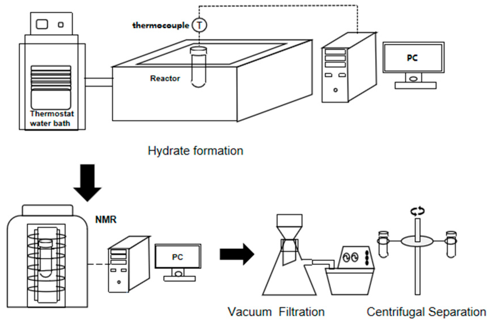
2.1. Experimental Apparatus and Materials

Deionized water with a specific resistance of 18 MΩ was produced using Aquapro2S via reverse osmosis. CP and 22MB were purchased from Aladdin Industrial Corporation (Shanghai, China). An Oxford Instruments Low Field Nuclear Magnetic Resonance System was used (Figure S1, Abingdon, UK). The model of X-ray diffractometer used was a Bruker D8 Advance (Figure S2, Billerica, MA, USA) and the Raman spectrometer model was a LabRAM HR Evolutione (Figure S3, Horiba, Kyoto, Japan). The model of refrigeration constant-temperature circulating water bath was a Labtemp CC-4008E (Guangzhou, China). The model of the magnetic stirrer was an AS ONE CS-4 1-4609-25 (Osaka, Japan). The model of diaphragm vacuum pump was a GM-0.5A (Tianjin, China). The model of the high-speed freezing centrifuge was an H1850R (Changsha, China).

2.2. Experimental Procedure and Conditions

CP and 22MB were used to configure mixtures of different concentrations. The concentration of CP in the mixture was 70–95%. The experiment was divided into three parts. The experimental process is shown in Figure 1. The first part of the experiment was to verify whether hydrate can be formed. A sealed glass bottle was used as a reaction container. The 70% CP (20 mL) was mixed with water (80 mL) at 2 °C and the electromagnetic stirrer was set to 700 rpm. The reaction time was 12 h. It has been reported that it is very hard to form CP hydrate in the static state, while NMR measurements cannot be performed in the agitated state. So, detection by the nuclear magnetic resonance instrument was performed before and after the reaction. We measured the T2 distribution via the low-field NMR system using the following test parameters: time of recycle delay (RD) = 7500 ms; resonant frequency (RF) = 12.71 Hz; number of echoes (NOE) = 46,296; and the time between the 90° pulse and the first acquired echo (Tau) = 0.0127 ms.
The second part of the experiment was to detect the hydrate structure. The hydrate generated in the first part of the experiment was vacuumed and then centrifuged for 5 min at −5 °C and 4000 rpm to completely remove the residual liquid in the hydrate. The hydrate was ground into powder under the protection of liquid nitrogen, and then tested by XRD and Raman spectrometer. The measurement temperature for XRD and Raman was set to 250 K to prevent hydrate decomposition during the measurement process. X-ray diffraction analysis was conducted using filtered Cu Kα radiation (λ = 0.154 nm, operated at 40 kV and 40 mA). The 2θ range was set from 5° to 60°, with a step of 1.5° min−1. The Raman analysis was conducted using a 532 nm laser. The experiment was repeated with CP (20 mL) and water (80 mL) antisense as control group.
The purpose of the last part of the experiment was to verify the separation effect. Different concentrations of CP (70–95%) were used to generate hydrate under the above experimental conditions. The separated hydrates decomposed at 20 °C to produce pure CP and water. Because CP is insoluble in water, it was separated via liquid separation and its purity was measured using gas chromatography.
The equation for calculating the purification efficiency based on the proposed hydrate method is expressed as follows [32]:
Impurity   removal   ratio = C 0 C f C 0 × 100 %
where C0 is the initial concentration of impurity, and Cf is the concentration of impurity in the CP obtained from the decomposition of CP hydrate.
The hydrate conversion rate was calculated using equation [33]:
Conversion   ratio = m h m 0 × 100 %
where m0 is the mass of hydrate formation theoretically, and mh is the mass of hydrate formation actually.

3. Results and Discussion

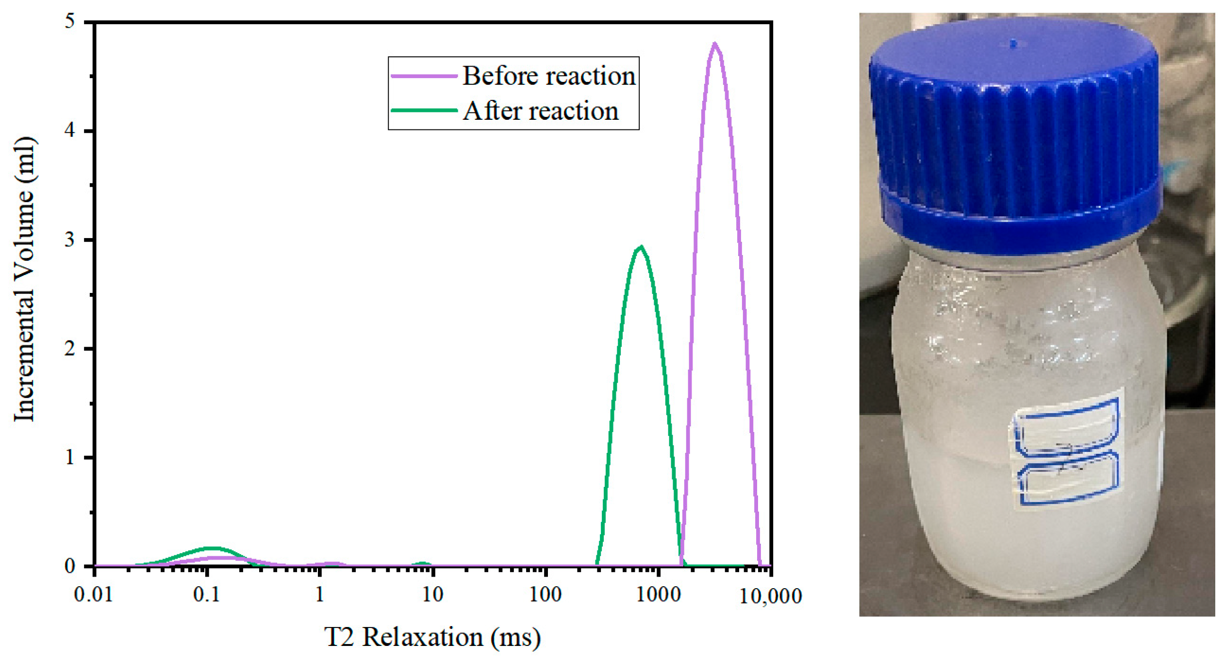
3.1. Nuclear Magnetic Resonance

Magnetic resonance imaging technology is a new optical measurement system often used in medical and biological science research. In addition, many researchers have conducted extensive research and observed the hydrate formation process by using nuclear magnetic resonance (NMR) imaging technology [34].
NMR imaging systems are mainly used to capture images of hydrogen protons in liquid water, and the nuclear-magnetic-signal intensity is proportional to the hydrogen proton content. It is known that the NMR of fluids close to solids can be quite different from that for pure fluids; these effects are strongly linked to the characterization of pore fluids and fluid distributions in porous media through NMR measurements [35]. During hydrate formation, hydrogen protons are mainly distributed in liquid water, and the transverse relaxation time of the hydrogen protons in the hydrate is significantly shorter than that in free water. Therefore, hydrate formation can be determined based on the nuclear-magnetic-signal value of water measured using the NMR system.
NMR data from before and after the reaction were measured, as shown in Figure 2. The 0.01–1 ms section represents the hydrate, and the peak area significantly increases after the reaction. The 10–10,000 ms section represents the water, and the peak area significantly decreases after the reaction [36]. The NMR results showed that the mixture of CP and 22MB reacted with water to form hydrates. Because the agitator used in the experiment was magnetic, measurements could not be made during hydrate formation. According to Kuang [36], in situ hydrate formation experiments can obtain more accurate data. However, electromagnetic stirrers cannot be used in in situ experiments. We attempted to conduct in situ hydrate formation experiments under static conditions, but no hydrate formation occurred within 12 h. So, we had to use experiments that were not in situ. The consumption of water can be calculated according to the change in the nuclear magnetic signal.

3.2. X-ray Diffraction

The periodic arrangement of atoms in the crystal creates conditions for light diffraction [37]. The wavelength of X-rays is similar to the distance between atoms, and this produces constructive interference at specific angles. Different diffraction patterns are produced by X-ray scattering from different atomic structures. X-ray diffraction (XRD) techniques use this principle to elucidate the crystalline nature of materials [38].
The hydrate crystals had three main structures: sI, sII and sH [39]. Cubic structure I contains small (0.4–0.55 nm) guests; cubic structure II generally occurs with larger (0.6–0.7 nm) guests; and hexagonal structure H may occur only with mixtures of both small and large (0.8–0.9 nm) molecules [40]. CP could react with water to form sII hydrates, and 22MB could not react with water to form sII hydrates. CP and 22MB can form sH hydrate with other small molecules.
The structural type of the hydrate was determined by analyzing its X-ray diffraction spectrum. Figure 3 shows a comparison between the X-ray diffraction (XRD) patterns of the hydrate generated by the mixture, the CP hydrate, ice and the sII hydrate. The XRD spectra of the ice and sII hydrate were determined by Yousuf [41].
The mixture of CP and 22MB reacted with water to form sII hydrate (Figure 3). The XRD wave patterns of the experimental group and the control group were consistent. Compared with the standard peak position, the measured peak position had a certain left deviation, which was caused by slightly different temperature and measurement error. In addition to the hydrate phase, significant ice diffraction peaks appeared in the XRD spectra of the two hydrate samples, owing to water condensation and mixing into the samples when the samples were ground under the protection of liquid nitrogen. Some peaks were not obvious, which was caused by insufficient grinding. No characteristic wave peak of sH hydrate was observed in the XRD spectrum of the mixture hydrate, preliminarily indicating that no hydrate was formed from 22MB.

3.3. Raman Spectroscopy

Raman spectroscopy is considered to be one of the most reliable and versatile tools for analyzing several materials under laboratory and field conditions [42]. Electromagnetic radiation interacts with matter through absorption, transmittance or scattering phenomena. This will cause the photon energy to change. The energy difference between the incoming photon and the outgoing one is called “Raman shift” [43].
CP and 22MB in the hydrated state exhibited different Raman shifts. By analyzing the Raman shift of the sample, the guest molecules in the hydrate could be determined.
The Raman peak position of the sample was the same as the CP hydrate (Figure 4). The Raman peak near 896 cm−1 indicated the respiratory ring vibration of CP [44]. The Raman peaks near 2876 and 2983 cm−1 corresponded to the C-H symmetric and C-H stretching vibrations of CP, respectively [45]. Based on these three Raman peaks, the formation of CP hydrate in the experiment was determined. According to Lv [46], the Raman peaks near 3160 and 3340 cm−1 corresponded to O-H stretching vibration. The Raman peaks near 3160 cm−1 corresponded to the coupled symmetric O-H stretching mode of tetrahedrally coordinated hydrogen-bonded water. The Raman peaks near 3340 cm−1 corresponded to the O-H stretching mode of incomplete-tetrahedral-coordination hydrogen-bonded water, indicating a water molecular-arrangement disorder. The peak positions of the Raman spectra showed no difference for the formed CP hydrates with and without 22MB, which indicated that the addition of 22MB had no impact on the structure of the produced CP hydrates.

3.4. Purification Results

The recovery ratio and purification effect are important parameters to indicate the performance of purification methods. We calculated the reduction rate of impurity (22MB) content in CP to express the purification effect. Because the purified CP was obtained by decomposition of hydrate, we used the hydrate formation ratio to replace the CP recovery ratio. If the purity of CP is too low, it will affect the formation of hydrate, so we tried to purify CP in the concentration range of 70–95%.
The impurity removal ratio determines the quality of the produced CP, which can be monitored by gas chromatography–mass spectrometry and then calculated by Equation (2). For the initially highest mass fraction of CP (95%), the purified CP fraction reached to 98.56%, corresponding to an impurity removal ratio of 71.2%. As shown in Figure 5, with the increase in the initial mass fraction of CP from 70% to 95%, the impurity removal ratio only ranged between 37.6% and 25.3% when using suction filtration alone. With further centrifugal separation, the impurity removal ratio reached from 73.4% to 71.2%. These results demonstrated that the initial CP concentration had a weak effect on the impurity removal ratio, and the solid–liquid separation approach (i.e., suction filtration and centrifugal separation in this study) had a significant influence on impurity removal ration. The mass fraction of CP obtained by ordinary distillation is 80~85% [47]. Hydrate-based separation technology can obtain CP with higher purity than ordinary distillation. According to the detection using XRD and Raman, it was found that the hydrate structure did not contain 22MB, but that a certain amount of 22MB may be attached to the surface of the hydrate. Therefore, efficient solid–liquid separation methods may become the focus of follow-up research.
As can be seen in Figure 6, the hydrate formation rate was between 40.5% and 80.6%. The hydrate formation ratio increased with the increase in CP purity. This is because the existence of 22MB will inhibit the formation of CP hydrate to a certain extent. The hydrate formation rate of 90% CP was almost the same as that of 95% CP, which means that the lower concentration of 22MB had little effect on hydrate formation. The hydrate conversion ratio calculated by measuring water consumption through T2 was different from the hydrate conversion ratio measured by weighing. This may have been caused by the formation of condensed water on the surface of the reactor during T2 measurement. The higher the hydrate formation rate, the more CP will be recovered. When the purity of CP is too low, it is difficult to form hydrates. In Figure 5 and Figure 6, it can be observed that the conversion ratio of hydrates has almost no effect on impurity removal. Conventional technology to obtain high-purity CP requires increasing the number of plates in the distillation column, which will greatly increase energy consumption. In contrast, our technology had excellent results in purifying high-purity CP.
Currently, as shown in Table 1, ED is commonly used in industry to purify CP. The process consists of two parts, namely, an ED column and a recovery distillation column. If you want to effectively separate CP and 22MB, the number of stages needs to be above 60. This means complex processes and high energy consumption. More importantly, the conventional method requires gasification of CP, which is toxic and explosive. Our technology is relatively safe.

4. Conclusions

This study shows that the hydrate-based process has great potential for treating CP and 22MB mixtures. When the experimental temperature is 2 °C and the electromagnetic stirrer is 700 rpm, this method can effectively deal with CP with a mass fraction of 70–95%. The recovery ratio of CP is 40.5–80.6%, and the impurity removal ratio is more than 71.2%. When 70% CP is to be purified, the recovery ratio of CP is 40.5%. When 95% CP is to be purified, the recovery ratio of CP is 80.6%. This method performs better in the treatment of high-purity CP, which is impossible for ordinary distillation. The volume of ED equipment is too large to handle small amounts of CP. The proposed technique may be valuable for separating high-purity CP from petroleum. This hydrate-based separation technology also has the potential to be expanded to other azeotropes.

Supplementary Materials

The following supporting information can be downloaded at: https://www.mdpi.com/article/10.3390/en16124681/s1, Figure S1: Nuclear Magnetic Resonance System; Figure S2: X-ray diffractometer; Figure S3: Raman spectrometer.

Author Contributions

Conceptualization, X.H. and H.D.; methodology, L.S.; software, X.H., C.Y. and M.L.; validation, L.Z.; investigation, X.H.; data curation, X.H., C.Y. and M.L.; writing—original draft, X.H.; writing—review editing, L.Z.; supervision, L.Y. and J.Z.; funding acquisition, J.Z. and Y.S. All authors have read and agreed to the published version of the manuscript.

Funding

This work was supported by the National Natural Science Foundation of China (grant numbers 52020105007, 52025066, 52006024, and U21B2065) and the Fundamental Research Funds for the Central Universities (grant number DUT22LAB130).

Data Availability Statement

The data presented in this study are available on request from the corresponding author.

Conflicts of Interest

The authors declare no conflict of interest.

References

  1. Pereiro, A.B.; Araújo, J.; Esperan, A.J. Ionic liquids in separations of azeotropic systems—A review. J. Chem. Thermodyn. 2012, 46, 2–28. [Google Scholar] [CrossRef]
  2. Fair, J.R. The workhorse today & tomorrow—Distillation. Chem. Eng. 2002, 109, 108. [Google Scholar]
  3. Lei, Z.; Li, C.; Chen, B. Extractive Distillation: A Review. Sep. Purif. Rev. 2003, 32, 121–213. [Google Scholar] [CrossRef]
  4. Mahdi, T.; Ahmad, A.; Nasef, M.M. State-of-the-Art Technologies for Separation of Azeotropic Mixtures. Sep. Purif. Rev. 2015, 44, 308–330. [Google Scholar] [CrossRef]
  5. Marschner, R.F.; Burney, D.E. Cyclopentane and Neohexane in Petroleum. Ind. Eng. Chem. 2002, 44, 1406–1408. [Google Scholar] [CrossRef]
  6. Zhou, F.; Xu, A.; Jiang, F. Study on the Process of Cyclopentane Oxidation to Cyclopentanol and Cyclopentanone. Fine Spec. Chem. 2020, 28, 5–9. [Google Scholar]
  7. Tian, Y.; Sun, J.; Wang, Z. 50 kt/a Fine separation of mixed pentane isomers. Chem. Prog. 2005, 24, 27–31. [Google Scholar]
  8. Qi, L.; Cui, J.; Xu, R. Selection of Cyclopentane/Neohexane Separation Extracts by COSMO-SAC Method and Process Simulation. J. Chang. Univ. 2021, 33, 43–49. [Google Scholar]
  9. Fu, M.L. Extractive Distillation of Alkane/Cycloalkane Feed Employing Mixed Solvent. U.S. Patent No. 4,948,470A, 14 August 1990. [Google Scholar]
  10. Sun, Y.B.; Zhao, Q.M.; Gao, Z.R. Development of extraction rectification of cyclopentane/2.2-methyl butane. Chem. Eng. 2012, 26, 17–19. [Google Scholar]
  11. Fandino, O.; Ruffine, L. Methane hydrate nucleation and growth from the bulk phase: Further insights into their mechanisms. Fuel 2014, 117, 442–449. [Google Scholar] [CrossRef] [Green Version]
  12. Moridis, G.J.; Collett, T.S.; Boswell, R. Gas Hydrates as a Potential Energy Source: State of Knowledge and Challenges; Springer: New York, NY, USA, 2013; Volume 37, pp. 977–1033. [Google Scholar]
  13. Wang, J.; Wang, Q.; Meng, Y. Flow characteristic and blockage mechanism with hydrate formation in multiphase transmission pipelines: In-situ observation and machine learning predictions. Fuel 2022, 330, 125669. [Google Scholar] [CrossRef]
  14. Park, K.N.; Hong, S.Y.; Lee, J.W.; Kang, K.C.; Lee, Y.C.; Ha, M.G.; Lee, J.D. A new apparatus for seawater desalination by gas hydrate process and removal characteristics of dissolved minerals (Na+, Mg2+, Ca2+, K+, B3+). Desalination 2011, 274, 91–96. [Google Scholar] [CrossRef]
  15. Steinar, G.J. Method for Production of Gas Hydrates for Transportation and Storage. U.S. Patent No. 5,536,893, 16 July 1996. [Google Scholar]
  16. Xue, Q.; Wang, X.; Li, Z. Application progress of hydrate utilization technology. Chem. Prog. 2021, 40, 722–735. [Google Scholar]
  17. Dong, H.; Wang, J.; Xie, Z. Potential applications based on the formation and dissociation of gas hydrates. Renew. Sustain. Energy Rev. 2021, 143, 110928. [Google Scholar] [CrossRef]
  18. Sun, L.; Sun, H.; Yuan, C. Enhanced clathrate hydrate formation at ambient temperatures (287.2 K) and near atmospheric pressure (0.1 MPa): Application to solidified natural gas technology. Chem. Eng. J. 2023, 454, 140325. [Google Scholar] [CrossRef]
  19. Xu, C.G.; Chen, Z.Y.; Cai, J. Study on Pilot-Scale CO2 Separation from Flue Gas by the Hydrate Method. Energy Fuels 2014, 28, 1242–1248. [Google Scholar] [CrossRef]
  20. Huang, L.; Liang, M.; Bei, L. Experimental Studies of the Separation of C2 Compounds from CH4 + C2H4 + C2H6 + N2 Gas Mixtures by an Absorption−Hydration Hybrid Method. Ind. Eng. Chem. Res. 2013, 52, 2707–2713. [Google Scholar]
  21. Zhang, L.W.; Chen, G.J.; Guo, X.Q. The partition coefficients of ethane between vapor and hydrate phase for methane + ethane + water and methane + ethane + THF + water systems. Fluid Phase Equilibria 2004, 225, 141–144. [Google Scholar] [CrossRef]
  22. Li, S.; Fan, S.; Wang, J. Clathrate Hydrate Capture of CO2 from Simulated Flue Gas with Cyclopentane/Water Emulsion. Chin. J. Chem. Eng. 2010, 18, 202–206. [Google Scholar] [CrossRef]
  23. Hassanpouryouzband, A.; Yang, J.; Tohidi, B. Insights into the CO2 Capture by Flue Gas Hydrate Formation: Gas Composition Evolution in Systems Containing Gas Hydrates and Gas Mixtures at Stable Pressures. ACS Sustain. Chem. Eng. 2018, 6, 5732–5736. [Google Scholar] [CrossRef]
  24. Czarnota, R.; Knapik, E.; Wojnarowski, P. Carbon Dioxide Separation Technologies. Comm. Min. PAS 2019, 64, 487–498. [Google Scholar]
  25. Lashof, D.A.; Ahuja, D.R. Relative contributions of greenhouse gas emissions to global warming. Nature 1990, 344, 529–531. [Google Scholar] [CrossRef]
  26. Zhang, B.; Wu, Q. Thermodynamic Promotion of Tetrahydrofuran on Methane Separation from Low-Concentration Coal Mine Methane Based on Hydrate. Energy Fuels 2010, 24, 2530–2535. [Google Scholar] [CrossRef]
  27. Ko, G.; Lee, J.; Seo, Y. Separation efficiency and equilibrium recovery ratio of SF6 in hydrate-based greenhouse gas separation. Chem. Eng. J. 2020, 405, 126956. [Google Scholar] [CrossRef]
  28. Kim, E.; Ko, G.; Seo, Y. Greenhouse Gas (CHF3) Separation by Gas Hydrate Formation. ACS Sustain. Chem. Eng. 2017, 5, 5485–5492. [Google Scholar] [CrossRef]
  29. Wang, X.L.; Chen, G.J.; Yang, L.Y. Study on the recovery of hydrogen from refinery (hydrogen plus methane) gas mixtures using hydrate technology. Sci. China Ser. B-Chem. 2008, 51, 171–178. [Google Scholar] [CrossRef]
  30. Han, S.; Rhee, Y.W.; Kang, S.P. Investigation of salt removal using cyclopentane hydrate formation and washing treatment for seawater desalination. Desalination 2017, 404, 132–137. [Google Scholar] [CrossRef]
  31. Wu, L. Study on Separation Technology of Cyclopentane/Neohexane Mixture; China University of Petroleum: Beijing, China, 2017. [Google Scholar]
  32. Sun, H.; Sun, L.; Zhao, Y. A combined hydrate-based method for removing heavy metals from simulated wastewater with high concentrations. J. Environ. Chem. Eng. 2021, 9, 106633. [Google Scholar] [CrossRef]
  33. Zhang, L.; Sun, M.; Wang, T. An in-situ MRI method for quantifying temperature changes during crystal hydrate growths in porous medium. J. Therm. Sci. 2022, 31, 1542–1550. [Google Scholar] [CrossRef]
  34. Zhang, L.; Dong, H.; Dai, S. Effects of depressurization on gas production and water performance from excess-gas and excess-water methane hydrate accumulations. Chem. Eng. J. 2022, 431, 133223. [Google Scholar] [CrossRef]
  35. Watson, A.; Chang, C.T. Characterizing porous media with NMR methods. Prog. Nucl. Magn. Reson. Spectrosc. 1997, 31, 343–386. [Google Scholar] [CrossRef]
  36. Kuang, Y.; Zhang, L.; Song, Y. Quantitative determination of pore-structure change and permeability estimation under hydrate phase transition by NMR. AIChE J. 2020, 66, 16859. [Google Scholar] [CrossRef]
  37. Chauhan, C.; Bioanal, J.A. Powder XRD Technique and Its Application. J. Anal. Bioanal. Tech. 2014, 5. [Google Scholar] [CrossRef] [Green Version]
  38. Dann, S.E. Reactions and Characterization of Solids; Royal Society of Chemistry: London, UK, 2000; pp. 64–65. [Google Scholar]
  39. Liu, C.; Ye, Y. Natural Gas Hydrates Experimental Techniques and Their Applications; Springer: Berlin/Heidelberg, Germany, 2013. [Google Scholar]
  40. Sloan, E. Fundamental principles and applications of natural gas hydrates. Nature 2003, 426, 353–359. [Google Scholar] [CrossRef]
  41. Yousuf, M.; Qadri, S.B.; Knies, D.L. Novel results on structural investigations of natural minerals of clathrate hydrates. Appl. Phys. A 2004, 78, 925–939. [Google Scholar] [CrossRef]
  42. Kudelski, A. Analytical applications of Raman spectroscopy. Talanta 2008, 76, 1–8. [Google Scholar] [CrossRef]
  43. Orlando, A.; Franceschini, F.; Muscas, C. A Comprehensive Review on Raman Spectroscopy Applications. Chemosensors. 2021, 9, 262. [Google Scholar] [CrossRef]
  44. Lv, Q. Formation Kinetics of Cyclopentane plus Methane Hydrates in Brine Water Systems and Raman Spectroscopic Analysis. Energy Fuels 2015, 29, 6104–6110. [Google Scholar] [CrossRef]
  45. Lo, C.; Zhang, J.; Somasundaran, P. Raman Spectroscopic Studies of Surfactant Effect on the Water Structure around Hydrate Guest Molecules. J. Phys. Chem. Lett. 2010, 1, 2676–2679. [Google Scholar] [CrossRef]
  46. Lv, Q.; Li, X. Raman Spectroscopic Studies on Microscopic Mechanism of CP—CH 4 Mixture Hydrate. Energy Procedia 2017, 142, 3264–3269. [Google Scholar] [CrossRef]
  47. Nuchteera, I.; Thirasak, P.; Chavagorn, M. Cyclopentane Purification from Multicomponent Azeotropic Mixtures. Comput. Aided Chem. Eng. 2020, 48, 277–282. [Google Scholar]
  48. Peng, K. Design and Optimization of Cyclopentane Separation Wall Distillation Tower; Dalian University of Technology: Dalian, China, 2021. [Google Scholar]
Figure 1. Experimental system.
Energies 16 04681 g001
Figure 2. T2 distribution of hydrate generated from the mixture of CP and 22MB and a real picture of the hydrate.
Energies 16 04681 g002
Figure 3. XRD spectra of hydrates of two samples showing characteristic peak positions of ice and sII hydrates in lower half.
Energies 16 04681 g003
Figure 4. Raman characterization of samples.
Energies 16 04681 g004
Figure 5. Effect of mass fraction of CP on impurity removal ratio.
Energies 16 04681 g005
Figure 6. Effect of mass fraction of CP on hydrate conversion ratio.
Energies 16 04681 g006
Table 1. Comparison of extractive distillation and hydrate separation technology.
Extractive DistillationHydrate Separation Technology
Process stagesaddition of extractant, vaporization (22MB), flow, vaporization (CP), condensationformation, separation, decomposition
DeviceED column (42~65 plates)recovery distillation column (10~36 plates)formation reactordecomposition reactor
Temperature (°C)52.23 (overhead)~114.79 (bottom)51.78 (overhead)~162.64 (bottom)220
Pressure (kPa)110160110135101101
AdditiveN,N-dimethyl formamide (DMF)water
Feed: Additives1:101:4
References[31,47,48]
Disclaimer/Publisher’s Note: The statements, opinions and data contained in all publications are solely those of the individual author(s) and contributor(s) and not of MDPI and/or the editor(s). MDPI and/or the editor(s) disclaim responsibility for any injury to people or property resulting from any ideas, methods, instructions or products referred to in the content.

