Article

Alternative Surface-Mounted Permanent Magnet Topology for Reducing Voltage and Torque Harmonics in Shaft Generators

1
Electric Power Machinery Research Department, HD Hyundai Electric, Seongnam 13553, Republic of Korea
2
Department of Electrical Engineering, Hanyang University, Seoul 14763, Republic of Korea
*
Author to whom correspondence should be addressed.
Energies 2023, 16(12), 4649; https://doi.org/10.3390/en16124649
Submission received: 14 April 2023 / Revised: 1 June 2023 / Accepted: 8 June 2023 / Published: 12 June 2023
(This article belongs to the Topic Future Generation Electric Machines and Drives)

Abstract

:
Traditional diesel generators on a merchant ship, composed of a wound rotor synchronous generator and a four-stroke diesel engine, supply electrical power for various loads. Recently, shaft generators for merchant ships have been increasingly replacing diesel generators to reduce CO2 emissions through fuel efficiency improvement. In particular, permanent magnet synchronous generators have replaced induction generators due to their high-efficiency characteristics at light loads. The surface-mounted permanent magnet rotor can be a suitable topology owing to the relatively short constant power range. This generator can also operate as a motor according to the propulsion mode, so minimizing the harmonics of the induced voltage with the torque pulsation being essential. This paper proposes an alternative surface permanent magnet topology. Three magnets comprise one pole, with one bread-loaf magnet and two rectangular magnets. It helps to simplify the magnetization and assembly of the rotor because of the flat bottom shape of the magnet. Due to the low remanence of two rectangular magnets at the pole edge, this rotor structure effectively makes the air-gap magnetic flux density sinusoidal with production costs reduced. The step-skew suppresses higher-order harmonics. The total harmonic distortion comparison of the two-dimensional finite element analysis and the no-load test result shows under 6% difference from the interior permanent magnet prototype machine. A comparison of harmonic characteristics with other rotors shows that the proposed modular pole has sufficient competitiveness compared to the tapered bread-loaf type. It can be applied as a substitute for the tapered bread-loaf magnet in direct-drive ship propulsion systems and is expected to shorten the manufacturing process and time.

1. Introduction

Conventional merchant ships have several diesel generators to supply electrical power for various devices, e.g., cranes and pumps. The required electrical power and load fluctuation decide the diesel generator system number and rated power combinations. This generator installed inside the hull is a power generation system that combines a four-stroke engine and a wound-field synchronous generator. Usually, synchronous generators have six to ten poles for the engine’s rated speed range of 720 to 1000 rpm. These generators operate at the same speed. An automatic voltage regulator controls the generator’s terminal voltage at the same level in response to voltage and frequency fluctuations caused by load variation. Meanwhile, a two-stroke engine is usually installed at the stern for ship propulsion and operates at less than 200 rpm. This engine shows a relatively high specific fuel oil consumption (SFOC) compared to the four-stroke engine. Utilizing this high SFOC characteristic, a shaft generator installed between the two-stroke engine and the propeller can be an alternative to partially eliminate the one or two diesel generators applied in large merchant ships. As a result, shaft generators have been widely used for merchant ships to enhance fuel efficiency and thus reduce CO2 emissions. This kind of generator can also operate as a motor operated by ship operation mode. In generator mode, the low voltage harmonic is the primary design requirement not to make additional harmonic losses in the winding and core parts. While in motoring function, low torque pulsation composed of cogging torque and torque ripple is a critical design requirement to reduce acoustic noise and mechanical vibration. The application of permanent magnet synchronous generators has been increasing recently owing to superior high-efficiency characteristics compared to induction machines, especially at light loads.
Ideal alternating current (AC) synchronous machines have pure sinusoidal air-gap flux density, making no voltage harmonics and torque pulsation in no-load and load operations. Several electromagnetic phenomena occur in real machines, e.g., magnetic saturation in electrical sheets, slot opening in the stator core, and non-sinusoidal air-gap flux density from the magneto-motive force in the rotor. These electromagnetic phenomena increase the harmonics in the air-gap flux density, which in turn deteriorates the voltage and output torque waveforms. Magnetic saturation is inevitable in high-power rotating machines to reduce volume and weight. The stator wire cross-section is rectangular, especially in high-voltage rotating machines, ensuring enough dielectric and mechanical strength. In this case, the slot opening width is determined by considering the current density and the corresponding heat dissipation performance. Therefore, in the actual design, one proper solution to reduce harmonics in the voltage and torque is a rotor design approach to make the air-gap flux density more sinusoidal.
Due to their relatively short constant power range, shaft generators can have surface-mounted permanent magnet (SPM) rotors. The SPM rotor design approach to reduce voltage harmonics and torque pulsation by making quasi-sinusoidal air-gap magnetic flux density can be classified into two categories: harmonic reduction method and harmonic cancellation method. Previous research suggested six harmonic reduction methods: Halbach array, magnet segmentation, pole shaping, magnet shifting, modular pole, and pole arc ratio optimization, including different magnet widths. The Halbach array consists of several magnet pieces, while the magnetization directions of the magnet pieces are magnetized in different directions to make the air-gap flux density sinusoidal. This quasi-sinusoidal flux density makes little cogging torque and almost a sinusoidal voltage waveform, while the rotor rim is not essential because of self-shielding magnetization in small machines [1,2,3]. Still, there remains a disadvantage, especially in large appliances; permanent magnets with various magnetization directions are assembled into one rotor pole piece or magnetized. Moreover, since it has to withstand the disturbance transmitted from the main engine and propeller, the rotor must have a sturdy rotor rim connected to the main shaft. The second method is magnet segmentation, meaning one pole has many magnets with different widths [4,5,6,7,8]. This method positively affects the air-gap space harmonics, cogging torque, and magnet loss decrease. Since magnets of different widths must be magnetized and assembled, separate magnetizers for each magnet and manufacturing facilities are furnished in a large multi-pole machine. As each magnet is separated from the other, it is necessary to secure structural stability by constructing empty gaps with non-magnetic materials.
Tapering is the usual method of pole shaping [9,10,11,12,13,14,15,16,17,18,19,20,21]. In this structure, the magnet’s thickness in the center of one pole is thicker than that at the edge [13,14,15,16,17,18,19]. As a result, the air-gap length between the rotor and the stator core becomes non-uniform. This method is also very effective in making the air-gap flux density sinusoidal. However, although intensive research has been conducted on high-speed machines, arc or ring shapes were mainly studied for the purpose of using magnets efficiently. Another magnet shaping method is the addition of a third or higher harmonics to the magnet shapes [12,20,21]. Fundamental flux density in the air-gap can increase with the effect of the triploid harmonics on sinusoidal waveforms. Hence, the output torque increases, whereas the torque ripple also increases due to additional harmonics. The fourth method is magnet shifting. The distance between magnets is different, making an asymmetrical magnet arrangement. This method is mainly effective in reducing cogging torque [22,23,24,25,26,27,28,29,30,31]. However, the rotor has hundreds or more of magnets in a large rotating machine to minimize eddy current loss and temperature rise. A disadvantage is that an additional rotor balancing process is required owing to the asymmetry of the magnets. The fifth way is using a modular pole [32,33,34,35,36,37,38,39]. This way means combining two or more differently shaped magnets. Several studies have been conducted in all three directions: radial direction [32,33,34,35,36], tangential direction [37], and axial direction [38,39]. All the ways show a significant effect in improving the quality of the air-gap flux density. At the same time, reviewing the structural stability of the entire rotor to which the magnet is attached is essential. The sixth method is to optimize the pole arc ratio, including different magnet widths [5,14,27,28,38,40,41,42,43]. The main design variables in SPM rotors are magnet width and height, except for the arrangement and geometry of the magnet. The magnet should have sufficient thickness to secure magnetic stability considering demagnetization, but the designer can freely change the magnet width. However, the magnet width, i.e., the pole arc ratio, is generally different in order to minimize the voltage harmonic and torque ripple.
Skew is a representative method of the harmonic cancellation method. The skewed rotor or stator has a several axial step-core with a separation distance of usually one stator slot angle [27,42,43,44,45,46,47,48,49,50,51]. This method effectively cancels higher harmonics because the skewed structure operates as a low-pass filter. While continuous skew is usually applied to induction machines, step-skew can easily be used in SPM machines using separated magnets in the axial direction. Small electric motors have been targeted in previous papers, so most research has focused on arc-shaped magnets. This shape is challenging to handle in magnetization and assembly processes because of the pointed end of a large magnet’s width of 200 mm or more. In some designs, which are Halbach array, magnet segmentation, and modular pole, many magnets are arranged in a complex shape to reduce air-gap flux harmonics. In addition, it is difficult to find research results that consider simultaneously all the harmonics of voltage, cogging torque at no load, and torque ripple at load operation.
This paper proposes an alternative SPM topology comprising three separate magnets, incorporating a modular step-skewed rotor to make air-gap flux density more sinusoidal and reduce the harmonics in the voltage and torque. Three magnets have one bread-loaf magnet and two rectangular-shaped magnets. Since the three divided magnets have a flat bottom, it helps to simplify the magnetization process. Additionally, in the assembling process of the rotor, damage to the magnet can be reduced, and the safety of workers can be improved. Due to the low remanence of two rectangular magnets at the pole edge, this rotor structure effectively reduces the air-gap harmonic flux and production cost. The high-order harmonics are further intensively reduced using step-skew, maximizing the overall harmonic component reduction effect. Section 2 cover the comparison of the two-dimensional (2-D) finite element (FE) analysis and the no-load test result. The fundamental voltage deviation is under 2%, and the total harmonic distortion (THD) difference is less than 6%. This confirms that the deviation between the FE model and the test result is minimal for the interior magnet (IPM) prototype machine. Section 3 shows the design approach of a proposed modular pole from air-gap flux density and the characteristics of the step-skew method. Section 4 represents the cogging torque minimization effect using the step-skewed rotor, simultaneously suppressing the harmonics of voltage and torque. The pole arc ratio, which suppresses voltage and torque harmonics simultaneously, does not match. A comparison of harmonic characteristics with other rotors shows that the proposed modular pole has sufficient competitiveness compared to the tapered bread-loaf type, which is very effective in reducing harmonics. In particular, the torque ripple suppression effect was found to be excellent for the prototype machine. The suggested modular pole can be applied as a substitute for the tapered bread-loaf magnet in direct-drive ship propulsion systems with a magnet width of over 200 mm and is expected to contribute to shortening the manufacturing process and time.

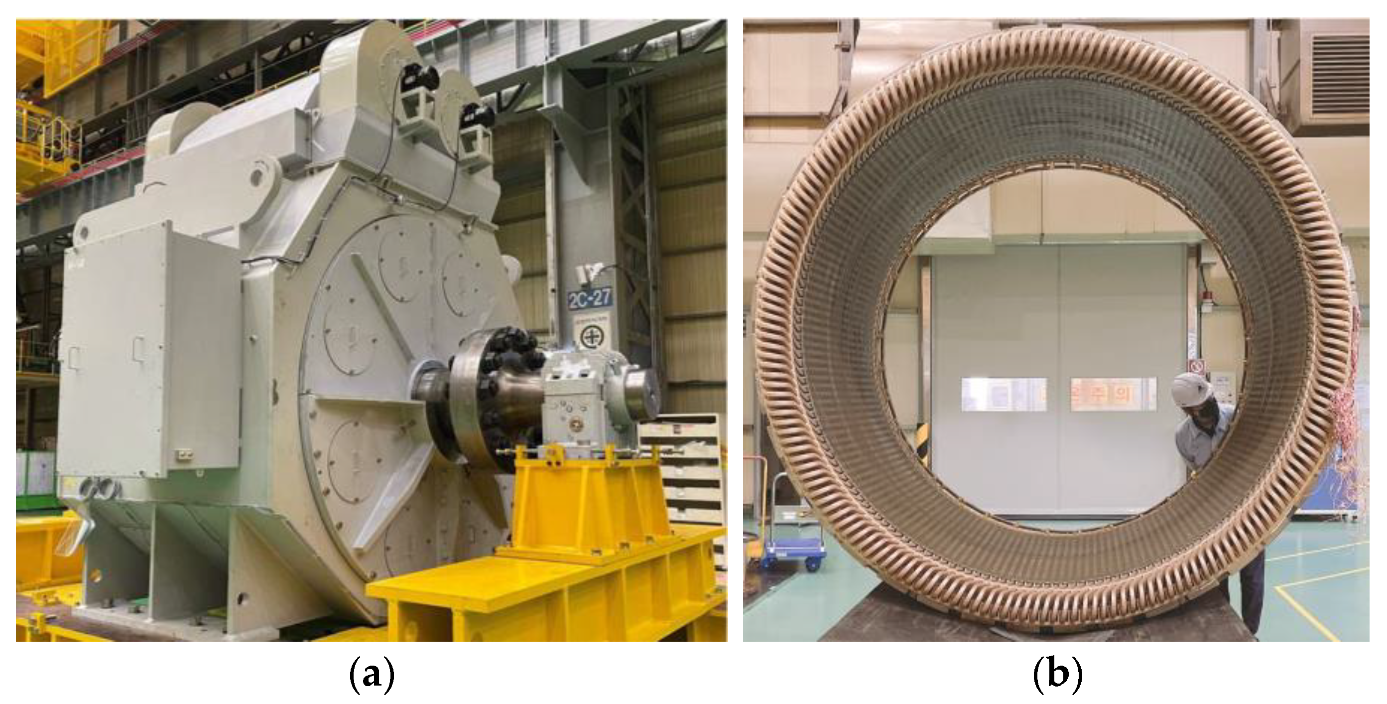
2. Interior Permanent Magnet Prototype Machine

Compared to SPM rotors, interior permanent magnet (IPM) rotors have high demagnetization resistance, structural stability, and wide-range field weakening capability due to the inherent characteristic of their shape. In order to improve the dynamic response characteristics and achieve weight reduction, an alternative design concept was derived for the SPM rotor. Based on the 2-D FE model, the no-load voltage characteristics of the prototype machine were analyzed, and the analysis consistency reviewed by comparing it with the test results.

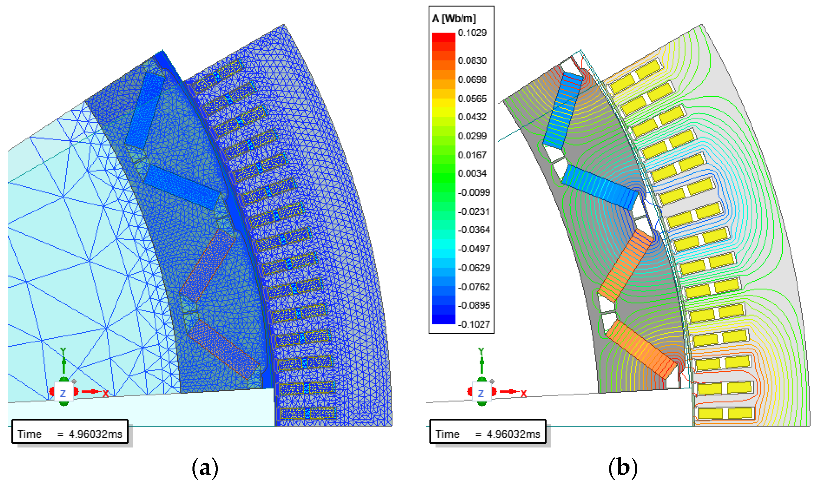
2.1. 2-D Finite Element Model and Analysis Condition

A 2-D FE model is used to reduce solving time rather than a three-dimensional (3-D) analysis. The 2-D model has only a two-pole region owing to the radial symmetry of the machine shown in Figure 1. A Dirichlet boundary condition is applied at the outer line of the stator core to reduce the solving region, and the periodic boundary condition is applied to the radial edge parts. The time-stepping method with a transient solver evaluates time harmonics in voltage and torque. In this case, the time step and mesh size need to be small enough to obtain a precise calculation result; the sampling number is 200 for calculating induced voltage harmonics, 720 for torque pulsation, and the mesh number in the air-gap layer is four. The number of triangular meshes is 19,532 in order to have enough accuracy, especially in the analysis of the cogging torque. The superposition method for each twisted rotor is suitable for considering the skew effect in the 2-D FE model. An ideal sinusoidal current source is applied to obtain the machine’s harmonics.

2.2. No-Load Test Result

A no-load test was conducted on a prototype machine. The tested machine is a three-phase, 2 MW, 500 V IPM synchronous machine for ship propulsion systems. The height of the frame is 2.9 m, and the width is 3.1 m excluding the upper heat exchanger. As shown in Figure 2a, a terminal box is installed on the left side of the frame, and a heat exchanger with fan motors is located on the top of the frame to generate sufficient airflow. Figure 2b shows the assembled stator core and winding assembly before vacuum impregnation. The stator and rotor cores consist of non-oriented electrical steel, 50PN400. Because of the electrical steel sheet’s dimensional limitations, several separated cores were assembled into the whole core. The stator winding was made in rectangular copper wire to reduce partial discharge and respond to the inverter’s instantaneous voltage. Compared to wound rotor synchronous machines, NdFeB magnet rotors minimize the loss generated in the rotor part. Power density can be improved since heat generation due to rotor loss is minimized. In the no-load test, the dynamo drives the machine at the rated speed, and the voltage is measured from stator terminals. Since the stator windings are open, there is no armature reaction owing to the stator magneto-motive force. Therefore, measuring the terminal voltage from the magneto-motive force of the magnet is possible. This is the first test required to measure whether the rotor is appropriately designed to meet the required specifications. From this test, we can also measure iron loss, mechanical loss, and noise. The line-to-line voltage waveform was measured with an oscilloscope. Harmonic components and THD up to the 100th harmonic can be calculated using the international electro-technical commission (IEC) 60034-1 standard. According to this standard, the THD value of the terminal voltage during no-load operation must be less than 5%. The test and analysis results of no-load voltage are presented together in Figure 3.
The test result is compared to the 2-D FE analysis result to verify the accuracy of the induced voltage harmonics. The fundamental deviation between the test and analysis is less than 2%. Figure 3 is a modified result, so the fundamental wave component is 100%. The seventh harmonics occurs prominently, and its magnitude is about 0.5% to the fundamental and can be confirmed to be small enough to be ignored. In addition, the THD analysis result from the fundamental to the 100th order is 0.58%, and the deviation is less than 6% compared to the average value of 0.55% of the test results. Hence, the voltage harmonics of the prototype machine satisfy the IEC 60034-1 standard.

3. Proposed Surface Permanent Magnet Topology

Based on the IPM prototype machine, an SPM machine was designed. The rated speed increased from 56 to 65 rpm to partially include the field weakening region. The number of poles was selected as 32 to reduce the magnetic core weight due to the decrease in the magnetic circuit length. The proposed rotor topology started from a magnet arrangement method to make the no-load air-gap flux density sinusoidal. This model is characterized by arranging two kinds of magnets in the tangential direction and applying a step-skew to the rotor. The step-skew minimizes high-order harmonics, including cogging torque. The harmonics of voltage and torque can be adjusted by changing the magnet width.

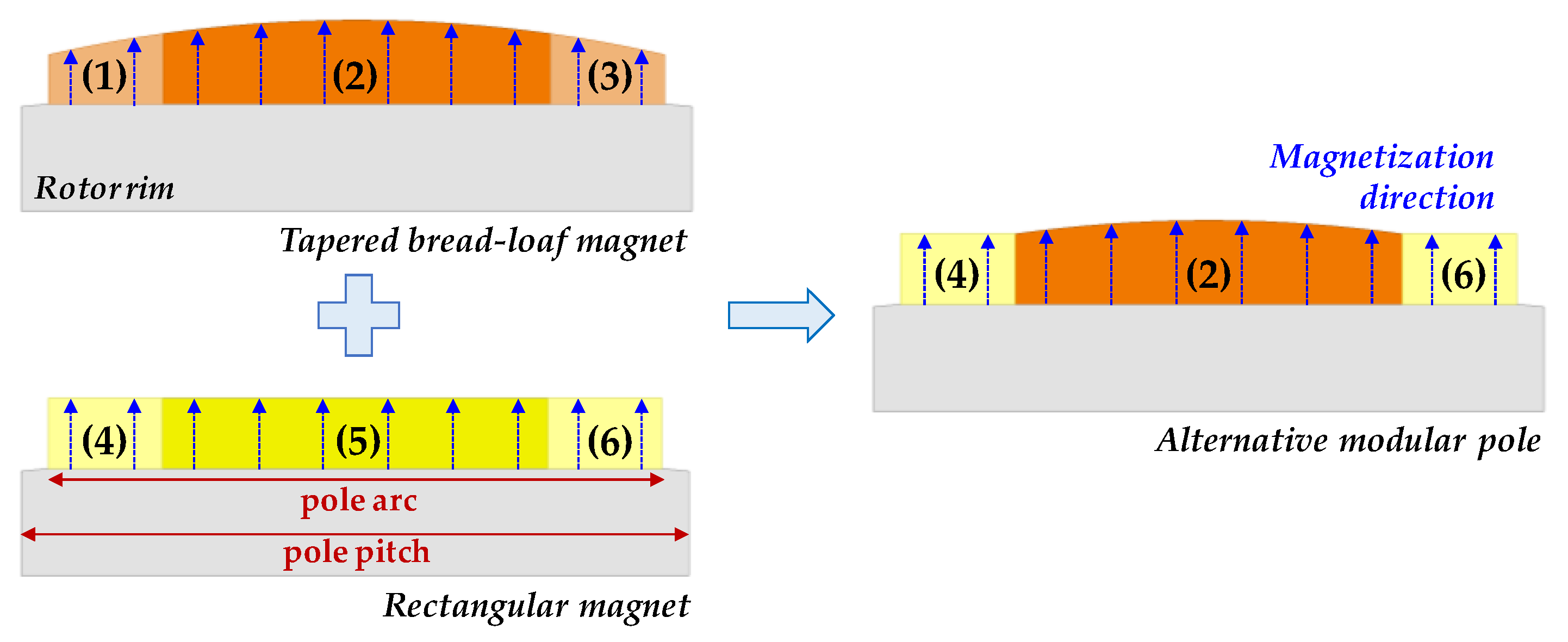
3.1. Design Approach in Radial Direction with Modular Pole

The tapered bread-loaf magnet has an excellent effect in making quasi-sinusoidal flux density in the air-gap, especially in low-speed large synchronous machines. Because of these machines’ relatively big diameter-to-axial length ratio, the magnet can have an almost flat bottom outside the rotor rim. This kind of magnet also can reduce the magnet bulk at the same magnetic loading which results in the rotor assembly manufacturing process being more efficient owing to its flat bottom. Table 1 represents the specification of a prototype machine together with the bread-loaf magnet. Based on the 2-D FE model in Table 1, Figure 4 shows the air-gap radial flux density on no-load for three kinds of magnets: conventional bread-loaf magnet, tapered bread-loaf magnet, and proposed modular magnet.
The tapered bread-loaf magnet and the proposed modular magnet have a maximum air-gap length of 12 mm. So, the minimum to maximum air-gap length ratio is 2. All the magnet poles have a pole arc ratio of 0.89, defined as the ratio of pole arc to pole pitch as in Figure 5. The 2-D FE model includes a magnetic saturation effect in electrical sheets using 50PN400 material data. The induced voltage at no-load is set as 500 V by adjusting remanence. The three air-gap flux densities appear symmetrical, centered at 90 degrees, and a smooth waveform about the pole center due to the bilateral symmetry-shaped magnet and no armature reaction. As the slot opening is filled with magnetic material, which means the same as that of the core, a conventional bread-loaf magnet shows almost isosceles trapezoidal flux density in ideal conditions. Under this condition, the no-load terminal voltage is reduced by more than 3% for all three models due to the leakage flux passing through the slot opening. The torque ripple increases owing to the reduced reluctance in the slot opening. When the slot opening effect is considered, as in Figure 4b, the air-gap flux waveform is distorted and shows higher harmonics due to the slotting effect from the stator core. Against ideal flux density, a conventional bread-loaf magnet shows that unnecessary magnetic flux occurs at the magnet edge. There are two options: increasing flux in the pole center or decreasing flux in the pole edge by modifying pole shape. A tapered bread-loaf magnet, which also means an irregular air-gap length, is a very effective rotor topology in making the air-gap flux density more sinusoidal as in Figure 4a and reducing eddy-current loss inside the magnet. However, this magnet shape has significant drawbacks: reduced mechanical stability and increased demagnetization possibility due to the relatively thin edge parts. Large magnets must be divided and used for manufacturing safety and uniform magnetization.
This paper suggests an alternative pole topology to reduce these drawbacks, as in Figure 5. The idea of the modular pole topology comes from a composite structure of a center magnet (2), from the tapered bread-loaf magnet and edge magnets (4, 6), and from the rectangular magnet. In other words, one pole has two kinds of magnet: one tapered bread-loaf magnet (2) is located in the center of the pole with relatively high remanence to satisfy the required induced voltage, and the location of two rectangular-shaped magnets (4, 6) is outside of the center magnet. These edge magnets will have relatively low remanence to make the air-gap flux density more sinusoidal.
Two-edge magnets can have any magnet, such as ferrite, alnico, SmCo, and NdFeB. However, in a high-powered rotating machine, the NdFeB magnet is the proper one due to the high coercivity to protect the magnet from partial demagnetization. The magnetization direction is parallel, which means a vertical direction to the magnet bottom, which makes the magnetization process easy.

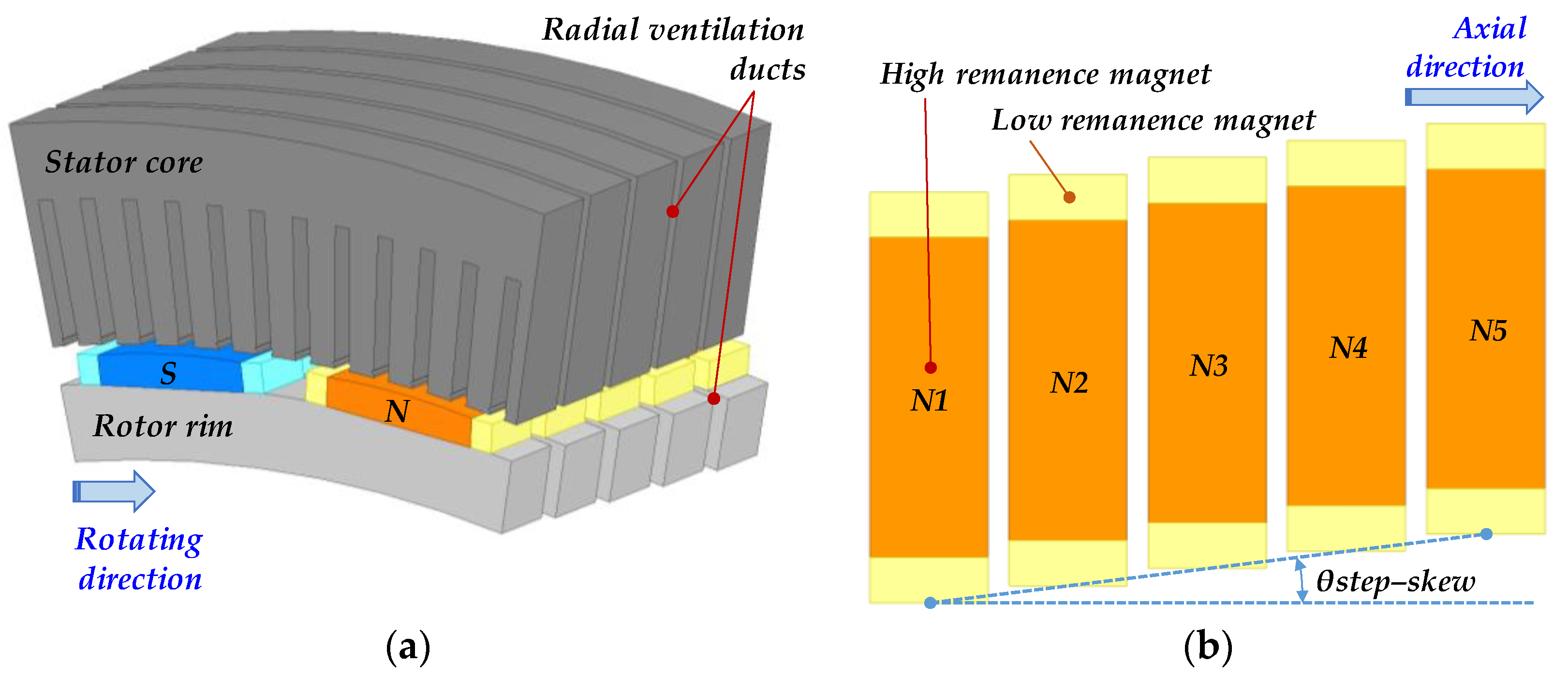
3.2. Design Approach in Axial Direction with Step-Skewed Rotor

In a large synchronous machine, a long axial core length over 300 mm makes it easy to have a step-skew over three steps or more. Figure 6a shows one axial module of the machine for two poles with five step-skewed magnets. Figure 6b shows one pole module. The pole arc ratio is 0.8, and the maximum air-gap length is 12 mm. The magnet width ratio between the center magnet and edge magnets is 3.5. A modular step-skewed rotor assembly consists of SPMs and rotor rims, as already shown in Figure 5. Two modules are axial symmetrical in the shape of an inverted V. This magnetically balanced rotor topology can reduce the axial force with the help of radial ventilation ducts. Several radial ducts are located between the core packets to increase cooling performance, especially in the winding. These radial ducts affect the decreasing inter-pole leakage flux owing to a relatively longer distance than that of the air-gap in this design. A kind of magnet cover is essential to protect the bundle of magnets in both the manufacturing process and in the shipyard and load operation; shown in Figure 6 to simplify the design approach. The rotor rim is connected to the intermediate shaft through additional shaft flanges. The stator core has segmented structures due to the length limit of the non-oriented electrical sheets. In this design, the maximum probable number of the segmented stator core in the circumferential direction is 8. The shape of the stator winding is rectangular, including several layer insulations, to withstand high-voltage with enough mechanical strength and to obtain enough dielectric strength and partial discharge characteristics. As the width of the slot opening is enough to assemble or insert the stator winding into the stator core, cogging torque substantially occurs with the additional effect of integer slot-distributed winding.
The cogging torque occurs by the interaction between the magneto-motive forces from the magnets and the reluctance variation inside the stator bore; in brief, air-gap permeance variation. The cogging torque can be easily observed in no-load operation, and a modular step-skewed rotor is one of the solutions to reduce or eliminate cogging torque. To cancel the harmonics by using step-skew, one period of harmonics is overlapped. It means the period of step-skew is determined as the least common multiple (LCM) of the number of poles (P) and slots (S). So, the total skew angle for (n)-step in Figure 6b can be calculated as (1) below:
θ s t e p s k e w = 360 ° L C M P , S · n 1 n
The prototype machine has 32 poles and 192 slots, and the step number is five. Thus, the skew angle between each core packet is 0.375 degrees.

4. Characteristic Comparison of Voltage and Torque

2-D FE analysis shows the cogging torque characteristics according to the skew angle and step number. Then, under a fixed air-gap magnetic field, the voltage and torque harmonic characteristics represent the optimal pole arc ratio of the prototype machine. The proposed modular pole has a sufficient harmonic suppression effect compared to the tapered bread-loaf magnet.

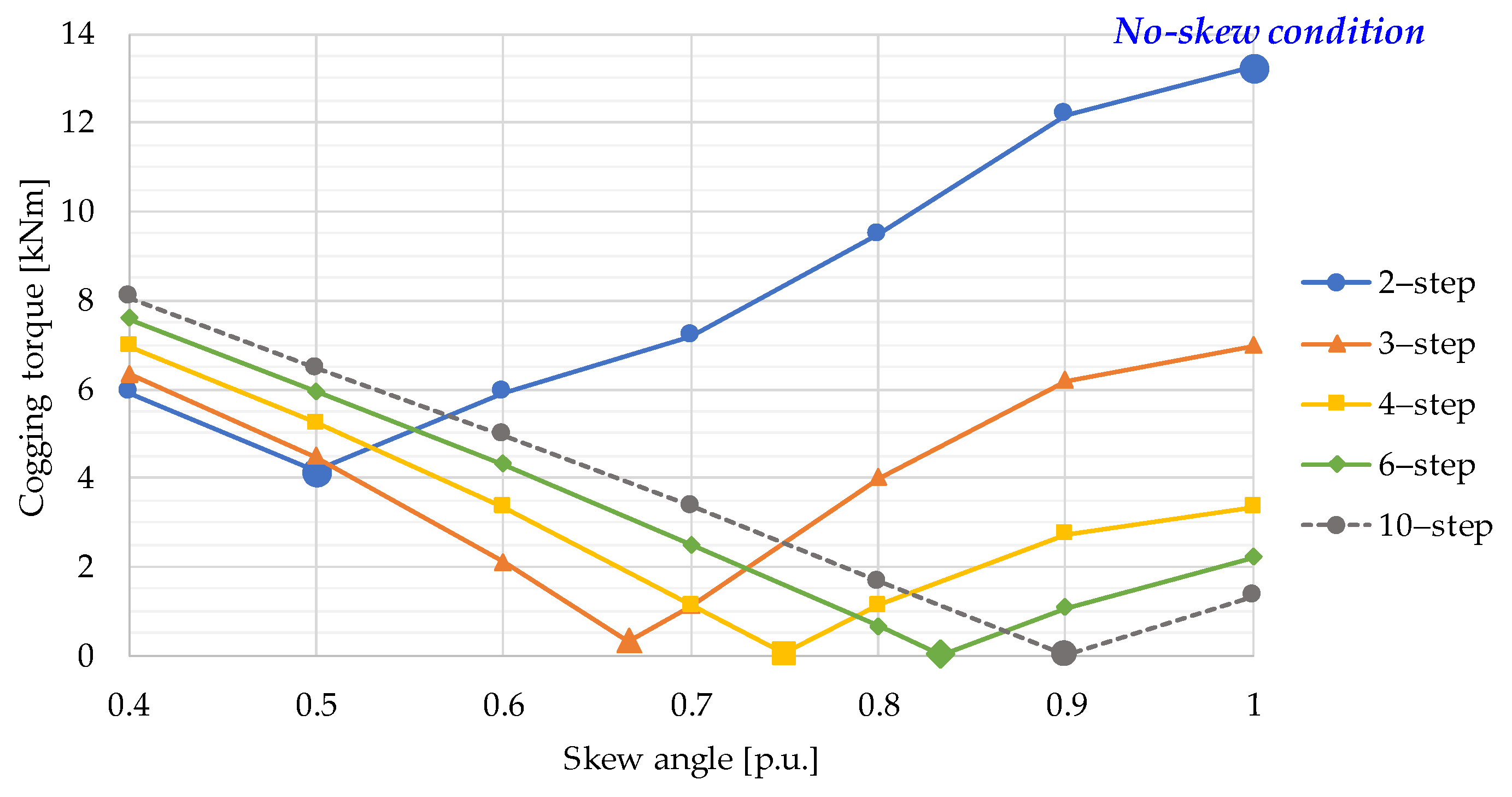
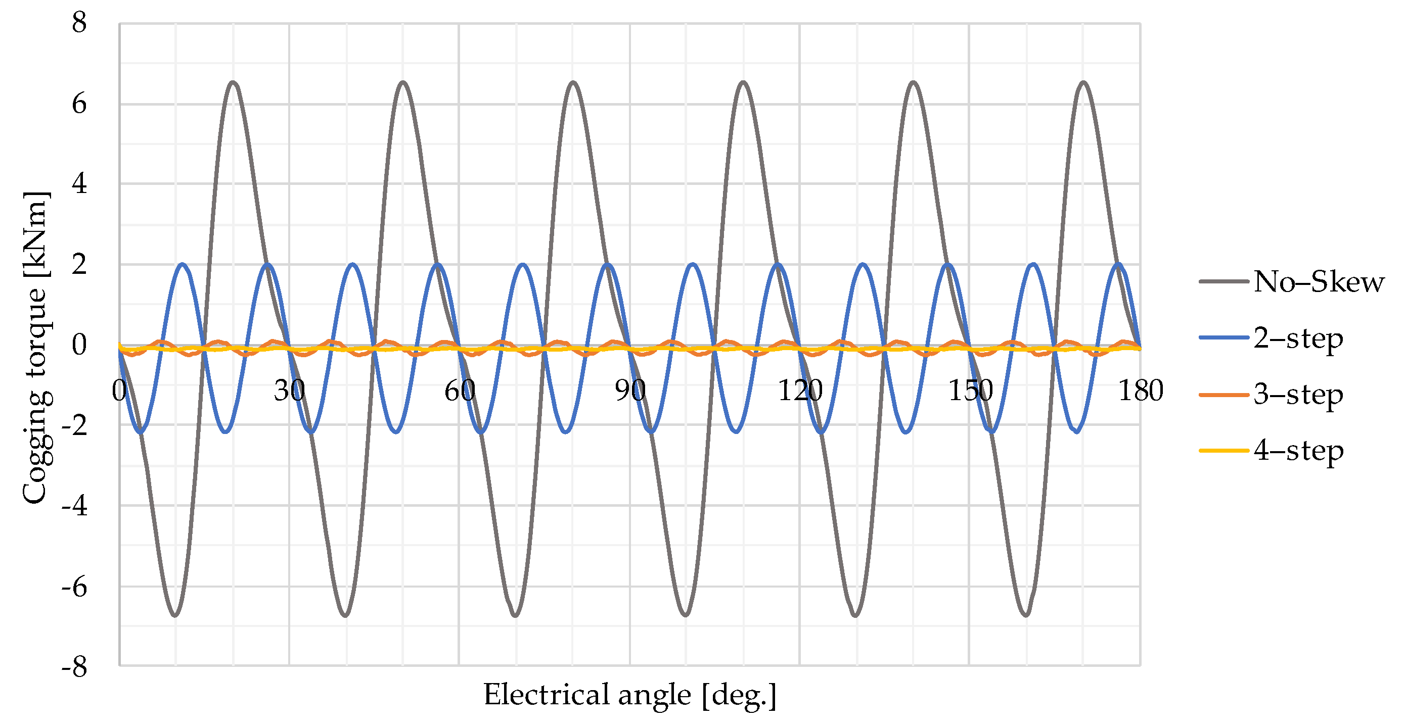
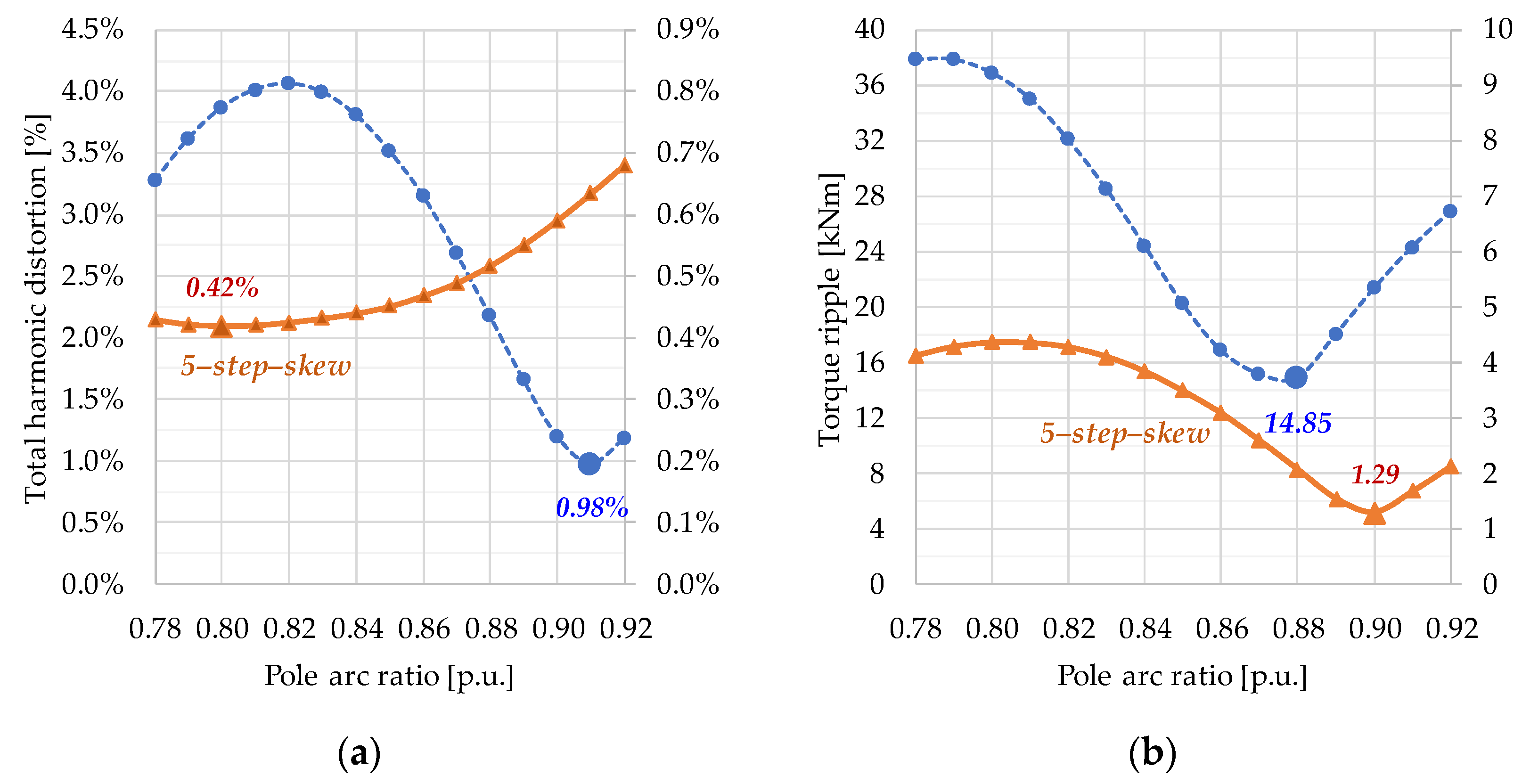
4.1. Cogging Torque Minimization with Step-Skew

A modular pole rotor with a pole arc ratio of 0.89 is used to determine the effect of the cogging torque suppression. The width ratio of the center magnet to the edge magnet is 0.6; this means the original bread-loaf magnet has a maximum air-gap length of 12 mm. Figure 7 shows the change in cogging torque magnitude as the step-skew is changed from two to ten steps. The big-blue point where the skew angle is 1.0 p.u. in the two-step-skew shows the same effect as not applying the skew. The amplitude of the cogging torque at this point is 13.26 kNm, which is 4.4% of the rated torque. This ratio signifies a tremendous cogging torque and may cause high vibration in the no-load operation. As the number of skew stages increases above four, the cogging torque appears to be less than 0.1% of the rated torque. As the number of skews increases further, the magnitude of the cogging torque eventually disappears. In addition, it can be seen that as the number of skews increases, the amount of change in cogging torque according to the skew angle decreases. In other words, using multiple step-skew can solve the cogging torque increase because of manufacturing tolerances.
Cogging torque occurs from the attractive force between the magnet in the rotor and the stator teeth. Therefore, based on the smooth rotor without skew, the period of cogging torque for one mechanical rotation can be calculated from the least common multiple of the number of poles (P) and stator slots (Q). As shown in Figure 8, the main cogging torque is a mechanically 192nd-order and an electrically 12th-order component. In two-step-skew, the fundamental component is canceled due to the superposition of the two cogging torque waveforms, and the 24th-order component becomes the main. When the number of steps increase over three, it can be seen that the cogging torque disappears, as shown in Figure 7 and Figure 8. Of course, the phase and magnitude of the cogging torque may fluctuate somewhat owing to the axial flux effect, including the end-leakage flux. This is expected not to be significant due to the minimized leakage flux by the radial ducts.

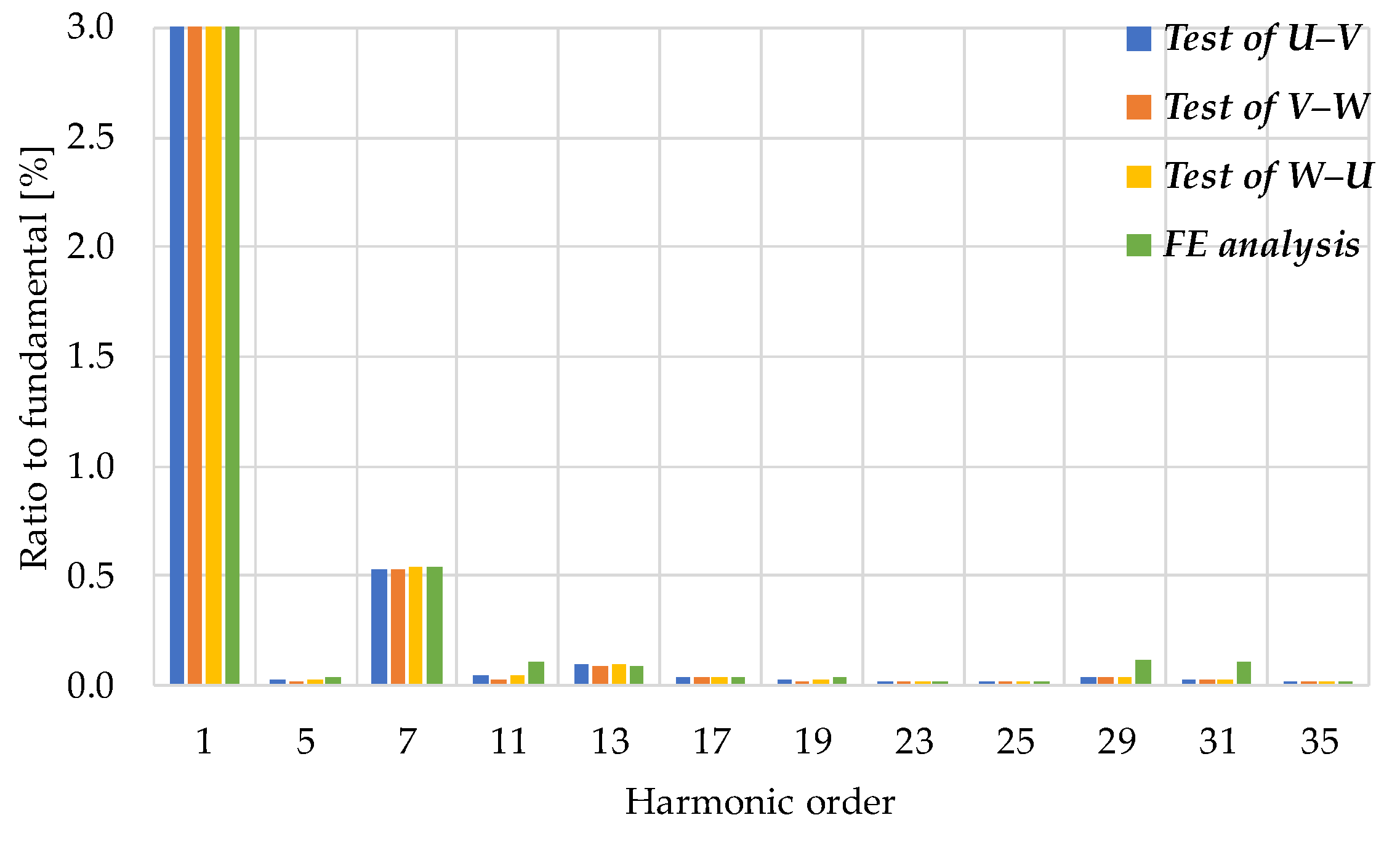
4.2. Harmonic Characteristics of Voltage and Torque Ripple

2-D FE models with a bread-loaf type magnet were used to find a proper pole arc ratio that minimizes both the voltage harmonics and torque ripple. The following assumptions were applied as preconditions to simplify the design approach. First, the dimensions of the stator winding, stator core, and rotor core are the same. Second, the magnet thickness is fixed as four times the air-gap length because the thickness of the magnet is a critical design variable to decide the degree of demagnetization, especially in SPM topology. In contrast, the remanence of the magnet is adjusted to have the same flux linkage in the stator winding for rated operation. Although the harmonic characteristics of the induced voltage can be evaluated from individual components, Equation (2) of the total harmonic distortion (THD) is used here to consider the first to the 100th harmonic component:
T H D = n = 2 100 U n U 1 2
where n is the harmonic order, U 1 is the first voltage harmonic and U n is n -th voltage harmonic.
Torque ripple, T r i p p l e , can be defined in various ways, and it is defined here as the deviation of the maximum and minimum torque to the average torque, as in Equation (3):
T r i p p l e = T m a x T m i n T a v g
where T m a x is the maximum torque, T m i n is the minimum torque, and T a v g is the average torque calculated from the 2-D model.
Figure 9 shows the harmonics of the induced voltage and the torque ripple according to the change in the pole arc ratio. It can be confirmed that the harmonic component significantly decreases according to the application of the skew. Even if the skew is applied, the fluctuation range of the harmonic component is extensive according to the pole arc ratio, e.g., the torque ripple has a 3.4 times difference.
An important matter in Figure 9 is that there is no pole arc ratio value where the voltage harmonic and torque ripple have a minimum simultaneously; the optimal pole arc ratio to reduce harmonics is 0.80 for back-electromagnetic force (EMF) and 0.90 for torque ripple. Table 2 shows the FE analysis results of pole arc ratio and maximum air-gap length variation, that is, the magnet width ratio, for the proposed modular pole. At this time, the relative permeability of the magnet is 1.05, and the remanence of the edge magnets is 1.0 T; an N28UH grade magnet has a remanence of 1.0 T at 80 degrees. The magnet grade means that N is the NdFeB magnet, 28 is the maximum energy product in KJ/m3, and UH is the maximum operating point of 180 degrees. Current phase angle control is excluded; the phase angle is 0 degrees. Each point of minimized THD and torque ripple are underlined for each pole arc ratio. The analysis result shows that as the maximum air-gap length increases, the remanence of the center magnet for the same induced voltage increases due to the fixed remanence of the edge magnet. Even when the pole arc ratio increases, the THD of the induced voltage can be kept under 0.4%; this shows robust voltage harmonic suppression. The torque ripple is minimized to the level of an induction motor with 0.35% of the rated torque at a pole arc ratio of 0.90—the same as the conventional bread-loaf magnet.

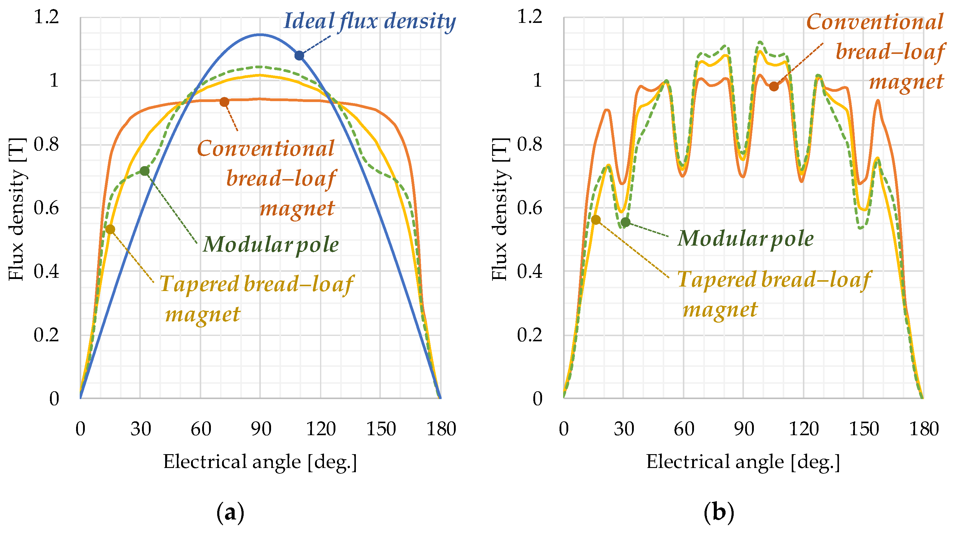
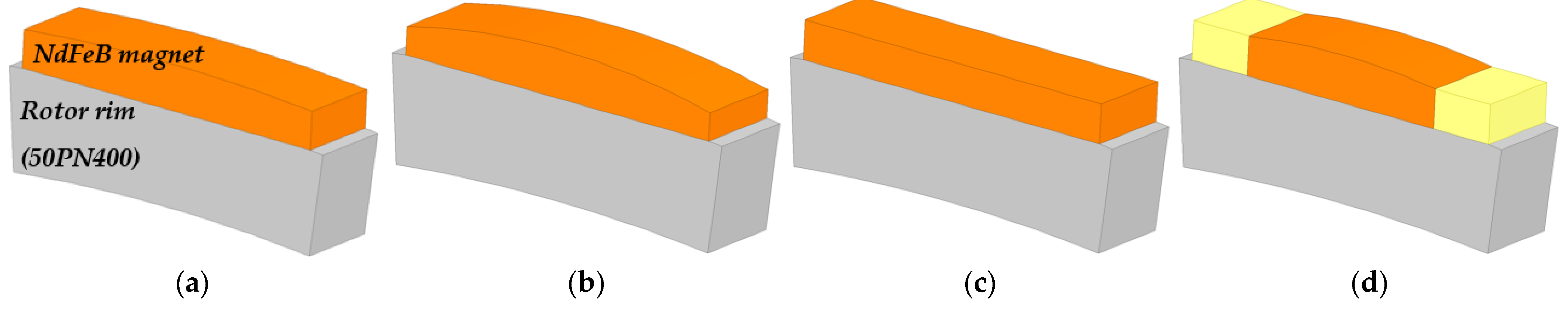
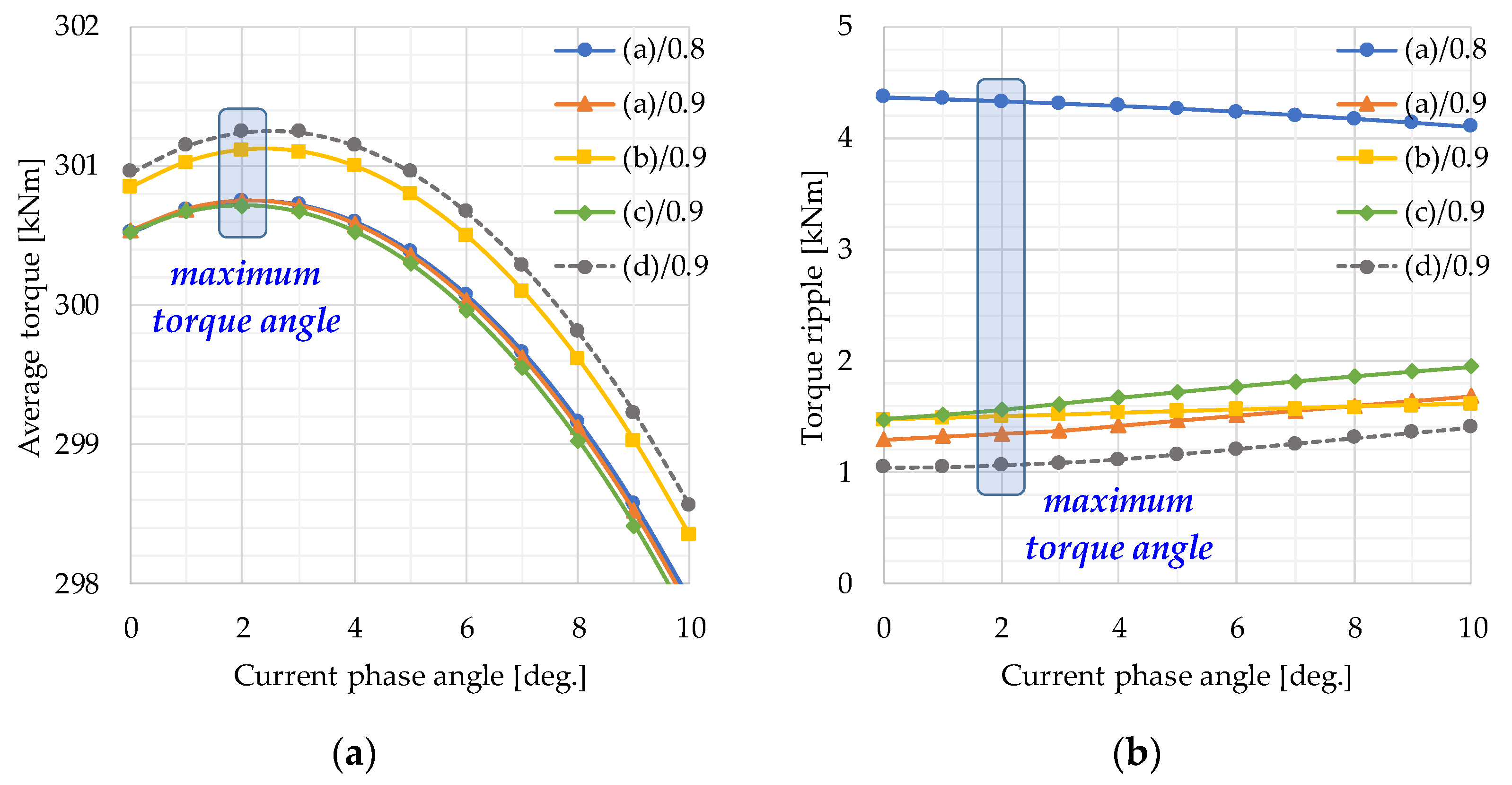
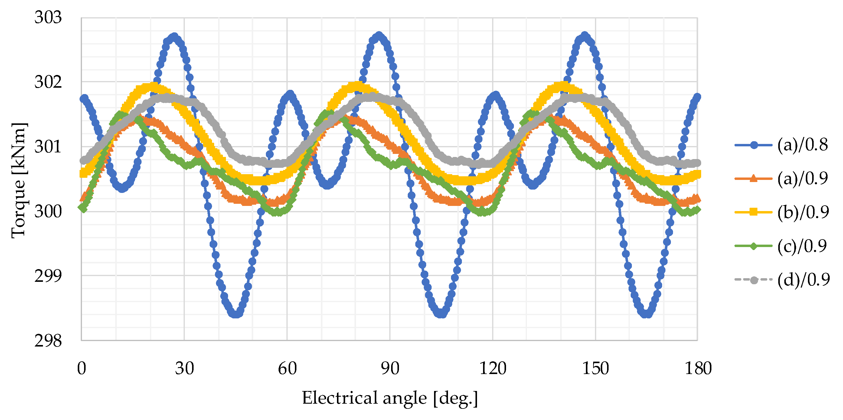
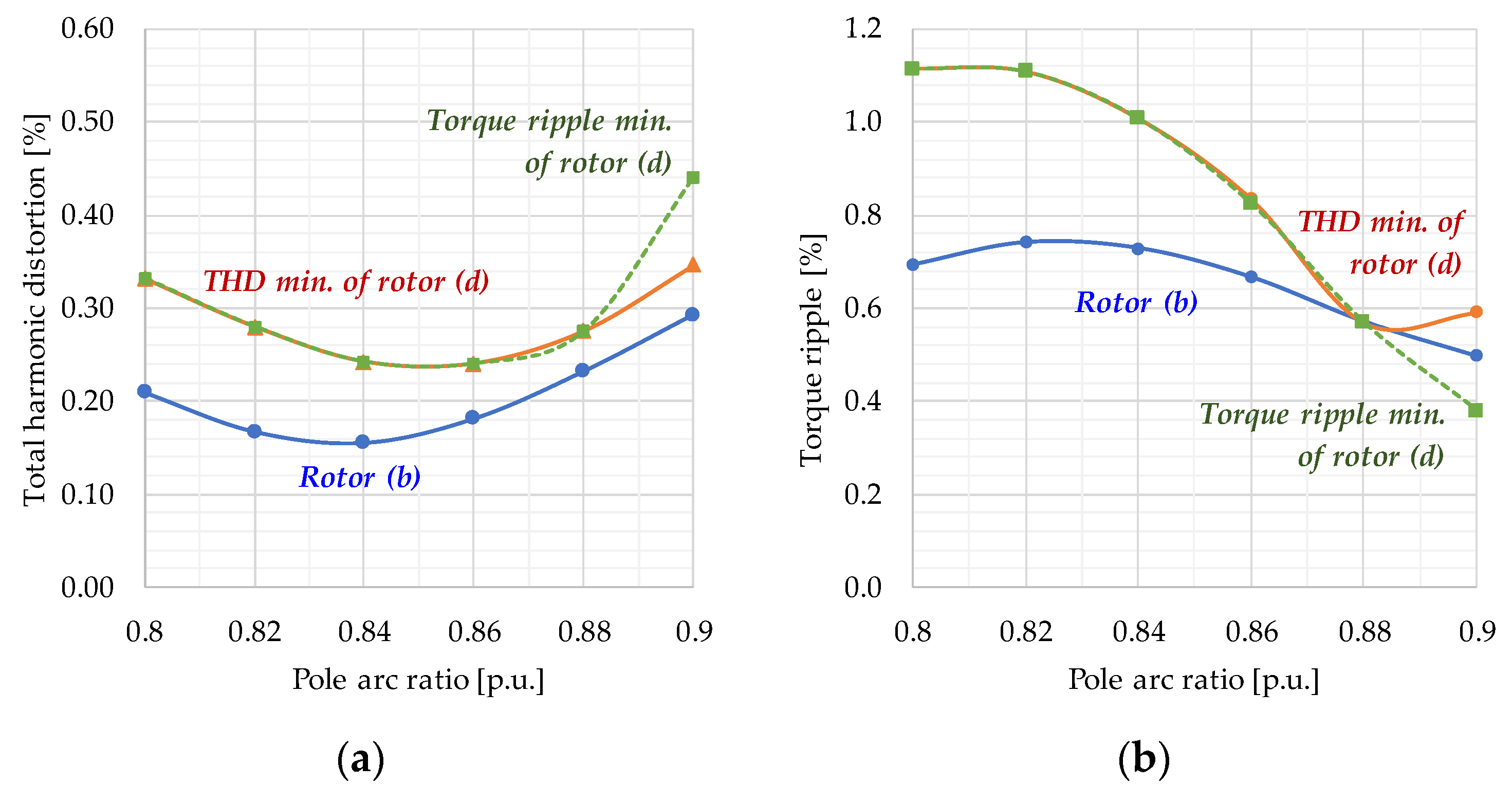
4.3. Characteristic Comparison of Four Different Magnet Rotors

It is essential to find out how effectively the proposed rotor design improves the harmonic characteristics. The shapes of the four magnets are presented in Figure 10. Generally, the tapered bread-loaf magnet of the rotor (b) is advantageous in generating a sinusoidal air-gap flux density, so it is often used in the SPM rotor. The rotor (c) represents a rectangular-shaped magnet and is widely applied to IPM synchronous motors because it is easy to magnetize and assemble. All magnets have a pole arc ratio of 0.9 for comparison.
The electromagnetic torque characteristics with the change of the current phase angle are summarized in Figure 11. Since operating at the maximum torque point on rated current is usually an efficient driving method, we first tried to find the maximum torque point. It can be seen that there is no significant difference in electromagnetic torque under the same pole arc ratio and magnet depth conditions. The non-uniform magnet depth of rotors (b) and (d) shows an increased electromagnetic torque owing to the reluctance torque, because of a slight difference between the d-axis and q-axis inductances in Figure 11a. It can also be seen that the phase angle of the current generating the maximum torque shifts by 2 degrees instead of zero owing to the different air-gap lengths and the relative permeability of 1.05. As the current phase angle increases in Figure 11b, the torque ripple shows an increasing or decreasing pattern according to the magnet shape.
Figure 12 shows the electromagnetic torque waveform based on an electrical angle of 180 degrees for each rotor design at the current phase angle of 2 degrees, where the maximum torque occurs. When the pole arc ratio is 0.8, the 6th and 12th harmonics dominate, but when the pole arc ratio is 0.9, the 12th harmonic component becomes the main component. In addition, rotor (d) has the most considerable average torque and minimizes the torque ripple. Table 3 represents the summarized characteristics of induced voltage and torque ripple for the four rotors in Figure 10. Compared to a tapered bread-loaf magnet with a pole ratio of 0.90, the proposed modular pole with a pole arc ratio of 0.89 has almost the same induced voltage harmonics as underlined. The torque ripple was reduced by 12% from 0.49% to 0.43%. When the pole arc ratio is 0.90 in the proposed modular pole, the torque ripple underlined in Table 3 is only 0.35% of the average torque. This topology shows the smallest torque pulsation in the load operation among the four-rotor topologies. From this result, we can see that the proposed rotor (d) has more of an effect on minimizing the voltage harmonic or torque ripple than rotor (b).
So far, the harmonic characteristics have been studied by changing the remanence of the magnet, that is, under fixed magnetic loading. Table 4 shows the harmonic characteristics of the proposed modular pole under the fixed magnet grades; the center magnet has N45UH, and the edge magnets have N28UH. The number of step-skews is five, and the current phase angle is two degrees. As the pole arc ratio increases, the width of the center magnet decreases, and the terminal voltage and average torque decrease together. At this time, the volume of the edge magnet increases, so the total magnet cost decreases. The step-skew suppresses the cogging torque regardless of the pole arc ratio and magnet width. The optimal design point where both harmonics are minimized simultaneously does not necessarily coincide—indicated in bold type. In particular, at the pole arc ratio of 0.9, where the torque ripple is minimized to 0.38%, it shows a lower torque ripple than the tapered bread-loaf type.
To verify the harmonic suppression characteristics of the proposed modular pole, Figure 13 shows the harmonic characteristics of voltage and torque, including the tapered bread-loaf magnet. A tapered bread-loaf magnet exhibits relatively low voltage harmonics. In contrast, the proposed modular pole can reduce voltage harmonics or torque ripple depending on the design point of view. In addition, when the pole ratio is 0.9, the lowest torque ripple is minimized in the proposed modular pole.

5. Conclusions

This research proposes a modular pole topology to reduce voltage harmonics or torque pulsation. The topology uses a step-skewed rotor to minimize the cogging torque at a negligible level. In addition, the combined magnet shape composed of a tapered bread-loaf magnet and two rectangular magnets minimizes the induced voltage and torque pulsation harmonics. The harmonic minimization effect of the proposed modular pole was verified by comparing the characteristics of the three topologies with the flat bottom based on the 2-D FE model. The topology proposed in this paper is expected to effectively reduce the voltage harmonics and torque pulsation of multipole permanent magnet rotors. In the future research, we will determine the voltage harmonics and torque pulsation fluctuations based on the 3-D FE model, considering the fringing and leakage flux effect in the axial direction. After manufacturing a prototype machine for the SPM rotor, the performance test will be used to verify the harmonic characteristics.

Author Contributions

Conceptualization, R.-W.S.; methodology, R.-W.S.; software, R.-W.S.; formal analysis, R.-W.S.; Investigation, R.-W.S.; writing—original draft, R.-W.S.; writing—review & editing, R.-W.S.; visualization, R.-W.S.; supervision, J.L.; project administration, R.-W.S. and J.L. All authors have read and agreed to the published version of the manuscript.

Funding

This research received no external funding.

Data Availability Statement

Not applicable.

Conflicts of Interest

The authors declare no conflict of interest.

References

  1. Halbach, K. Design of permanent multipole magnets with oriented rare earth cobalt material. Nucl. Instr. Meth. 1980, 169, 1–10. [Google Scholar] [CrossRef] [Green Version]
  2. Marinescu, M.; Marinescu, N. New concept of permanent magnet excitation for electrical machines. Analytical and numerical computation. IEEE Trans. Magn. 1992, 28, 1390–1393. [Google Scholar] [CrossRef]
  3. Zhu, Z.Q.; Howe, D. Halbach permanent magnet machines and applications: A review. IEE Proc. Elect. Power Appl. 2001, 148, 299–308. [Google Scholar] [CrossRef]
  4. Jeon, W.J.; Watanabe, H.; Nakamoto, A.; Kamiya, Y.; Onuki, T. Dynamic characteristics of synchronous motors applying a plural sub-magnets scheme to the rotor. IEEE Trans. Magn. 1999, 35, 3574–3576. [Google Scholar] [CrossRef]
  5. Lateb, R.; Takorabet, N.; Meibody-Tabar, F. Effect of magnet segmentation on the cogging torque in surface-mounted permanent-magnet motors. IEEE Trans. Magn. 2006, 42, 442–445. [Google Scholar] [CrossRef]
  6. Chaithongsuk, S.; Takorabet, N.; Meibody-Tabar, F. On the use of pulse width modulation method for the elimination of flux density harmonics in the air-gap of surface PM motors. IEEE Trans. Magn. 2009, 45, 1736–1739. [Google Scholar] [CrossRef]
  7. Isfahani, A.H. Analytical framework for thrust enhancement in permanent-magnet (PM) linear synchronous motors with segmented PM poles. IEEE Trans. Magn. 2010, 46, 1116–1122. [Google Scholar] [CrossRef]
  8. Ashabani, M.; Mohamed, Y.A.I. Multiobjective Shape optimization of segmented pole permanent-magnet synchronous machines with improved torque characteristics. IEEE Trans. Magn. 2011, 47, 795–804. [Google Scholar] [CrossRef]
  9. Hwang, S.M.; Eom, J.B.; Jung, Y.H.; Lee, D.W.; Kang, B.S. Various design techniques to reduce cogging torque by controlling energy variation in permanent magnet motors. IEEE Trans. Magn. 2001, 37, 2806–2809. [Google Scholar] [CrossRef]
  10. Dubois, M.R.; Polinder, H.; Ferreira, J.A. Magnet shaping for minimal magnet volume in machines. IEEE Trans. Magn. 2002, 38, 2985–2987. [Google Scholar] [CrossRef]
  11. Dubois, M.R.; Polinder, H.; Ferreira, J.A. Contribution of permanent-magnet volume elements to no-load voltage in machines. IEEE Trans. Magn. 2003, 39, 1784–1792. [Google Scholar] [CrossRef]
  12. Li, Y.; Zou, J.; Lu, Y. Optimum design of magnet shape in permanent-magnet synchronous motors. IEEE Trans. Magn. 2003, 39, 3523–3526. [Google Scholar] [CrossRef]
  13. Hsieh, M.F.; Hsu, Y.S. An investigation on influence of magnet arc shaping upon back electromotive force waveforms for design of permanent-magnet brushless motors. IEEE Trans. Magn. 2005, 41, 3949–3951. [Google Scholar] [CrossRef]
  14. Zheng, P.; Jing, Z.; Jianqun, H.; Jie, W.; Zhiyuan, Y.; Ranran, L. Optimization of the magnetic pole shape of a permanent-magnet synchronous motor. IEEE Trans. Magn. 2007, 43, 2531–2533. [Google Scholar] [CrossRef]
  15. Li, Y.; Xing, J.; Wang, T.; Lu, Y. Programmable design of magnet shape for permanent-magnet synchronous motors with sinusoidal back EMF waveforms. IEEE Trans. Magn. 2008, 44, 2163–2167. [Google Scholar] [CrossRef]
  16. Tavana, N.R.; Shoulaie, A. Analysis and design of magnetic pole shape in linear permanent-magnet machine. IEEE Trans. Magn. 2010, 46, 1000–1006. [Google Scholar] [CrossRef]
  17. Laskaris, K.I.; Kladas, A.G. Permanent-magnet shape optimization effects on synchronous motor performance. IEEE Trans. Ind. Elect. 2011, 58, 3776–3783. [Google Scholar] [CrossRef]
  18. Hong, H.S.; Yoo, J.H. Shape design of the surface mounted permanent magnet in a synchronous machine. IEEE Trans. Magn. 2011, 47, 2109–2117. [Google Scholar] [CrossRef]
  19. Pang, Y.; Zhu, Z.Q.; Feng, Z.J. Cogging torque in cost-effective surface-mounted permanent-magnet machines. IEEE Trans. Magn. 2011, 47, 2269–2276. [Google Scholar] [CrossRef]
  20. Zhu, Z.Q.; Wang, K.; Ombach, G. Optimal magnet shaping with third order harmonic for maximum torque in brushless AC machines. In Proceedings of the 6th IET International Conference on Power Electronics, Machines and Drives (PEMD 2012), Bristol, UK, 27–29 March 2012; pp. 1–6. [Google Scholar] [CrossRef]
  21. Wang, K.; Gu, Z.Y.; Zhu, Z.Q.; Wu, Z.Z. Optimum injected harmonics into magnet shape in multiphase surface-mounted PM machine for maximum output torque. IEEE Trans. Ind. Elect. 2017, 64, 4434–4443. [Google Scholar] [CrossRef]
  22. Li, T.; Slemon, G.R. Reduction of cogging torque in permanent magnet motors. IEEE Trans. Magn. 1988, 24, 2901–2903. [Google Scholar] [CrossRef]
  23. Ishikawa, T.; Slemon, G.R. A method of reducing ripple torque in permanent magnet motors without skewing. IEEE Trans. Magn. 1993, 29, 2028–2031. [Google Scholar] [CrossRef]
  24. Borghi, C.A.; Casadei, D.; Fabbri, M.; Serra, G. Reduction of the torque ripple in permanent magnet actuators by a multi-objective minimization technique. IEEE Trans. Magn. 1998, 34, 2869–2872. [Google Scholar] [CrossRef]
  25. Borghi, C.A.; Casadei, D.; Cristofolini, A.; Fabbri, M.; Serra, G. Application of a multiobjective minimization technique for reducing the torque ripple in permanent-magnet motors. IEEE Trans. Magn. 1999, 35, 4238–4246. [Google Scholar] [CrossRef]
  26. Breton, C.; Bartolome, J.; Benito, J.A.; Tassinario, G.; Flotats, I.; Lu, C.W.; Chalmers, B.J. Influence of machine symmetry on reduction of cogging torque in permanent-magnet brushless motors. IEEE Trans. Magn. 2000, 36, 3819–3823. [Google Scholar] [CrossRef]
  27. Bianchi, N.; Bolognani, S. Design techniques for reducing the cogging torque in surface-mounted PM motors. IEEE Trans. Ind. Appl. 2002, 38, 1259–1265. [Google Scholar] [CrossRef]
  28. Dosiek, L.; Pillay, P. Cogging torque reduction in permanent magnet machines. IEEE Trans. Ind. Appl. 2007, 43, 1565–1571. [Google Scholar] [CrossRef] [Green Version]
  29. Wang, D.; Wang, X.; Yang, Y.; Zhang, R. Optimization of magnetic pole shifting to reduce cogging torque in solid-rotor permanent-magnet synchronous motors. IEEE Trans. Magn. 2010, 46, 1228–1234. [Google Scholar] [CrossRef]
  30. Wang, D.; Wang, X.; Kim, M.K.; Jung, S.Y. Integrated optimization of two design techniques for cogging torque reduction combined with analytical method by a simple gradient descent method. IEEE Trans. Magn. 2012, 48, 2265–2276. [Google Scholar] [CrossRef]
  31. Tudorache, T.; Trifu, I. Permanent-magnet synchronous machine cogging torque reduction using a hybrid model. IEEE Trans. Magn. 2012, 48, 2627–2632. [Google Scholar] [CrossRef]
  32. Ree, J.D.L.; Boules, N. Magnet shaping to reduce induced voltage harmonics in PM machines with surface mounted magnets. IEEE Trans. Energy Convers. 1991, 6, 155–161. [Google Scholar] [CrossRef]
  33. Dubois, M.R.; Mailloux, G. Analytical calculation of no-load voltage waveforms in machines based on permanent-magnet volume integration. IEEE Trans. Magn. 2008, 44, 581–589. [Google Scholar] [CrossRef]
  34. Isfahani, A.H.; Vaez-Zadeh, S.; Rahman, M.A. Using modular poles for shape optimization of flux density distribution in permanent-magnet machines. IEEE Trans. Magn. 2008, 44, 2009–2015. [Google Scholar] [CrossRef]
  35. Isfahani, A.H.; Vaez-Zadeh, S.; Rahman, M.A. Performance improvement of permanent magnet machines by modular poles. IET Elect. Pow. Appl. 2009, 3, 343–351. [Google Scholar] [CrossRef]
  36. Zhu, Z.Q.; Shen, Y. Investigation of permanent magnet brushless machines having unequal-magnet height pole. IEEE Trans. Magn. 2012, 48, 4815–4830. [Google Scholar] [CrossRef]
  37. Dubois, M.R.; Polinder, H.; Ferreira, J.A. Varying magnetization orientation for permanent-magnet volume reduction in machines. IEEE Trans. Magn. 2003, 39, 1793–1799. [Google Scholar] [CrossRef] [Green Version]
  38. Fei, W.; Luk, P.C. Torque ripple reduction of a direct-drive permanent-magnet synchronous machine by material-efficient axial pole pairing. IEEE Trans. Ind. Elect. 2012, 59, 2601–2611. [Google Scholar] [CrossRef] [Green Version]
  39. Zhao, W.; Lipo, T.A.; Kwon, B.I. Torque pulsation minimization in spoke-type interior permanent magnet motors with skewing and sinusoidal permanent magnet configurations. IEEE Trans. Magn. 2015, 51, 8110804. [Google Scholar] [CrossRef]
  40. Vaez-Zadeh, S.; Isfahani, A.H. Multiobjective design optimization of air-core linear permanent-magnet synchronous motors for improved thrust and low magnet consumption. IEEE Trans. Magn. 2006, 42, 446–452. [Google Scholar] [CrossRef]
  41. Yang, Y.; Wang, X.; Zhang, R.; Ding, T.; Tang, R. The optimization of pole arc coefficient to reduce cogging torque in surface-mounted permanent magnet motors. IEEE Trans. Magn. 2006, 42, 1135–1138. [Google Scholar] [CrossRef]
  42. Jahns, T.M.; Soong, W.L. Pulsating torque minimization techniques for permanent magnet AC motor drives-a review. IEEE Trans. Ind. Elect. 1996, 43, 321–330. [Google Scholar] [CrossRef]
  43. Zhu, Z.Q.; Howe, D. Influence of design parameters on cogging torque in permanent magnet machines. IEEE Trans. Energy Convers. 2000, 15, 407–412. [Google Scholar] [CrossRef] [Green Version]
  44. Hwang, S.; Lieu, D.K. Design techniques for reduction of reluctance torque in brushless permanent magnet motors. IEEE Trans. Magn. 1994, 30, 4287–4289. [Google Scholar] [CrossRef]
  45. Hanselman, D.C. Effect of skew, pole count and slot count on brushless motor radial force, cogging torque and back EMF. IEEE Proc. Elect. Power Appl. 1997, 144, 325–330. [Google Scholar] [CrossRef]
  46. Zhu, Z.Q.; Ruangsinchaiwanich, S.; Ishak, D.; Howe, D. Analysis of cogging torque in brushless Machines having nonuniformly distributed stator slots and stepped rotor magnets. IEEE Trans. Magn. 2005, 41, 3910–3912. [Google Scholar] [CrossRef] [Green Version]
  47. Guemes, J.A.; Iraolagoitia, A.A.; DelHoyo, J.J.; Fernandez, P. Torque analysis in permanent-magnet synchronous motors: A comparative study. IEEE Trans. Energy Convers. 2011, 26, 55–63. [Google Scholar] [CrossRef]
  48. Jiang, J.W.; Bilgin, B.; Yang, Y.; Sathyan, A.; Dadkhah, H.; Emadi, A. Rotor skew pattern design and optimisation for cogging torque reduction. IET Elect. Syst. Transp. 2016, 6, 126–135. [Google Scholar] [CrossRef]
  49. Ocak, O.; Aydin, M. An innovative semi-FEA based, variable magnet-step-skew to minimize cogging torque and torque pulsations in permanent magnet synchronous motors. IEEE Access 2020, 8, 210775–210783. [Google Scholar] [CrossRef]
  50. Islam, M.S.; Shrestha, A.; Islam, M. Performance comparison of step skew in interior and surface-mount permanent magnet machines. In Proceedings of the 2021 IEEE Energy Conversion Congress and Exposition (ECCE), Vancouver, BC, Canada, 10–14 October 2021; pp. 3963–3968. [Google Scholar] [CrossRef]
  51. Nam, D.W.; Lee, K.B.; Pyo, H.J.; Jeong, M.J.; Yang, S.H.; Kim, W.H.; Jang, H.K. A study on core skew considering manufacturability of double-layer spoke-type PMSM. Energies 2021, 14, 610. [Google Scholar] [CrossRef]
Figure 1. 2MW permanent magnet synchronous machine for ship propulsion systems: (a) mesh plot; (b) no-load flux line.
Energies 16 04649 g001
Figure 2. 2MW permanent magnet synchronous machine for ship propulsion systems: (a) external appearance; (b) stator core and winding assembly.
Energies 16 04649 g002
Figure 3. Induced voltage harmonics from analysis and test results.
Energies 16 04649 g003
Figure 4. Air-gap radial flux density on no-load for one pole: (a) flux density with magnetic material in slot opening (ideal); (b) flux density with non-magnetic material in slot opening (real machine).
Energies 16 04649 g004
Figure 5. Alternative modular pole topology.
Energies 16 04649 g005
Figure 6. Modular pole and stator core: (a) rotor and stator core with radial ventilation ducts; (b) step-skewed magnet arrangement with the modular pole.
Energies 16 04649 g006
Figure 7. Cogging torque magnitude by the number of step-skews.
Energies 16 04649 g007
Figure 8. Cogging torque waveform by step number.
Energies 16 04649 g008
Figure 9. Harmonic characteristics of conventional bread-loaf magnet with or without 5-step-skew: (a) total harmonic distortion in induced voltage; (b) torque ripple.
Energies 16 04649 g009
Figure 10. Four different magnet rotors for one pole segment used in the performance comparison: (a) conventional bread-loaf magnet; (b) tapered bread-loaf magnet; (c) rectangular-shaped magnet; (d) proposed modular pole.
Energies 16 04649 g010
Figure 11. Electromagnetic torque characteristics with different current phase angles: (a) average torque variation; (b) torque ripple variation according to the change in the current phase angle.
Energies 16 04649 g011
Figure 12. Electromagnetic torque waveform of five different magnet rotors.
Energies 16 04649 g012
Figure 13. Harmonic characteristics of rotor (b) and (d): (a) total harmonic distortion in induced voltage; (b) torque ripple.
Energies 16 04649 g013
Table 1. Specification of a surface permanent magnet prototype machine.
Design VariableUnitSpecifications
Rated powerkVA2100
Rated speedrpm65
Number of phases-3
Number of poles-32
Number of slots-192
Stator outer diametermm2310
Stator inner diametermm2000
Minimum air-gap lengthmm6
Maximum magnet heightmm24
Rotor rim heightmm50
Core length except radial ductsmm900
Number of core packetEA20
Core material-50PN400
Skew angleno. of slotOne slot pitch on rotor
Table 2. Harmonic characteristics with three pole arc ratios of the proposed modular pole.
Pole Arc
Ratio
Maximum
Air-Gap
Length
Remanence
of Center
Magnet
Remanence
of Edge
Magnet
THD of
Induced
Voltage
Torque
Ripple
p.u.mmTT%%
0.8071.2671.0000.341.18
81.2971.0000.331.10
91.3261.0000.351.16
0.8991.2551.0000.310.48
101.2751.0000.310.43
111.2941.0000.340.42
0.9091.2501.0000.350.59
101.2691.0000.350.51
111.2871.0000.370.41
121.3051.0000.400.35
131.3221.0000.430.36
Table 3. Harmonic characteristics of four rotor topologies.
Rotor TopologyPole Arc
Ratio
Maximum
Air-Gap Length
Remanence
of Center
Magnet
THD of
Induced
Voltage
Average
Torque
Torque
Ripple
p.u.mmT%kNm%
(a) conventional bread-loaf magnet0.9061.1890.59300.50.43
(b) tapered bread-loaf magnet0.90121.2730.29300.80.49
(c) rectangular magnet0.9061.3800.74300.50.49
(d) proposed modular pole0.89101.2750.31300.80.43
0.90121.3050.40301.00.35
Table 4. Harmonic characteristics with six pole arc ratios of proposed modular pole.
Pole Arc
Ratio
Maximum
Air-Gap Length
Induced VoltageCogging
Torque
Average Torque
FundamentalTHDFundamentalRipple
p.u.mmVrms%%kNm%
0.807490.90.350.02%298.81.16%
8481.30.330.02%293.41.11%
9473.40.350.02%288.81.20%
0.827496.20.310.02%301.81.20%
8486.90.280.02%296.61.11%
9479.10.310.02%292.11.18%
0.847500.90.310.02%304.61.12%
8491.90.240.01%299.51.01%
9484.30.270.02%295.21.04%
0.867505.20.330.02%307.00.97%
8496.60.240.02%302.20.83%
9489.00.250.02%297.90.82%
0.887509.00.380.01%309.10.75%
8500.60.290.01%304.50.64%
9493.30.280.02%300.40.57%
10486.90.310.02%296.80.59%
0.907512.20.450.02%311.00.53%
8504.20.360.02%306.60.58%
9497.10.350.02%302.60.59%
10490.70.360.02%299.00.50%
11485.10.400.02%295.80.42%
12480.20.440.02%293.00.38%
13475.70.480.02%290.50.42%
Disclaimer/Publisher’s Note: The statements, opinions and data contained in all publications are solely those of the individual author(s) and contributor(s) and not of MDPI and/or the editor(s). MDPI and/or the editor(s) disclaim responsibility for any injury to people or property resulting from any ideas, methods, instructions or products referred to in the content.

