
Environmental and Technological Problems for Natural Gas Production in Permafrost Regions

Department of Gas and Gas Condensate Field Development and Operation, Gubkin University of Oil and Gas, 119991 Moscow, Russia
Energies 2023, 16(11), 4522; https://doi.org/10.3390/en16114522
Submission received: 14 April 2023
/
Revised: 26 May 2023
/
Accepted: 30 May 2023
/
Published: 5 June 2023
(This article belongs to the Special Issue Current Technical Problems of Conventional and Unconventional Oil and Gas Recovery)
Abstract
:Russia has unique technical and technological experience of gas field development in permafrost regions. According to this experience, different environmental and geocryological conditions require different technical solutions. Such problems as considerable subzero temperatures in geologic sections, great ice saturation of subsurface sediments, and gas and gas hydrate accumulations inside permafrost and immediately below it cause a series of dangerous consequences when gas production wells are in operation. These include back freezing, breaking well casings, well site subsidence when in production; movement and deformation of the wellhead caused by thawing of the rock massif around the well column when in operation; sudden and strong gas blowouts during well drilling, completion, and operation. To prevent possible accidents, different technical and technological solutions are applied: zoning of the field area according to the degree of complexity of geocryological conditions and the correction of future gas well cluster locations to avoid zones with extremely complex conditions; preliminary degassing of permafrost zones by shallow slim wells in places of future production well clusters; mechanical support of unstable production wells; installation of passive and active heat-isolation systems to the well construction and inside ground around wellheads. Key messages received during the development of gas fields at complex geocryological conditions are (consistently): preliminary careful geological engineering surveys and zoning of the field area, well clusters placed in areas with relatively soft geocryological conditions, preliminary degassing of permafrost depth intervals, passive and active heat isolation installation to the sub-wellhead part of the production well and around wellhead, and mechanical strengthening of unstable wells. Current plans are underway to utilize this experience for new gas discoveries in the Russian Arctic.
1. Introduction
Humanity needs new natural sources of energy for technological and industrial development. That does not mean the cancellation of old well-known sources such as renewables, biomass, and firewood. They have to occupy their own niche in the world’s energy balance, being oriented on individual and local energy supplies of low power. But according to the main industrial energy source substitution criteria suggested by Jevons [1], firewood and biomass were replaced by coal, coal was replaced by oil and, by logic, oil has now been replaced by natural gas as the main industrial source of energy, providing global competitiveness of the industry. Where do we obtain more natural gas? On-land, significant conventional natural gas fields in and around main energy-consumption regions on the Earth have already been explored and are under development or close to exhaustion. The USA has already started wide development of the last on-land natural gas resource—unconventional shale gas, which represents gas naturally generated and still remaining in mother rock (according to the organic theory of oil and gas generation) [2]. Large offshore natural gas fields around main energy-consumption regions are already under development. So, there are two ways of future, new gas developments: smaller fields in populated areas or hope of discovering new large fields in inhabited areas, such as the Arctic. There are many small gas fields in industrially developed areas, but the specific cost of gas production is too high to be competitive with gas produced in remote but large gas fields. So, the discovery and development of new, large natural gas fields are needed to satisfy industry needs.
One of the most promising regions of potential large gas field discovery is low-population on-land regions of permafrost spread. In the Northern Hemisphere, permafrost covers large areas of North America (Canada and Alaska), Greenland (Denmark), and Eurasia (Russia). According to their geological structure, Greenland and a major part of Canada’s permafrost areas are not favorable for natural gas field formation [3,4]. In Canada, gas and gas hydrate fields were discovered on the Arctic shore of the Beaufort Sea and in the Arctic Archipelago of Canada. They are not under development, due to long distances from the fields to main gas-consuming centers. In Alaska, there are the large oil fields of Prudhoe Bay and Kuparuk River, having been operated under permafrost conditions for a long time. But there are no gas and gas condensate fields under development. Moreover, permafrost conditions at the North Slope of Alaska are soft: from the surface, permafrost rocks are represented by large-grained sands and gravel, which have no considerable deformation when thawed [5,6].
The only country that has produced natural gas through the permafrost rock zone with different geocryological conditions for many decades is Russia. Since the first discovery of large gas fields in the middle of the 1960s in the north-east part of Europe, in West and East Siberia, the question of natural gas well operation in the permafrost zone became critical [7]. Having no experience of well drilling, during completion and operation in the permafrost zone and using technologies developed for warmer geologic sections, drillers and operators from the beginning of development have encountered such unexpected problems as drill mud and grouting mortar circulation loss, well column deformation in the expected operation time period (back freezing), and well-side subsidence after beginning operation [7,8,9,10]. But the most dangerous were unexpected gas blowouts from shallow permafrost when drilling, destabilization of the well-head after beginning operation, and intracasing and behind-the-casing gas leaks. A study of gas composition from these liberations and blowouts showed that this gas was generated in permafrost presumably by microbes decomposing buried organic matter [11,12,13,14,15,16].
Different problems attributed to the presence of permafrost rocks in geologic sections corresponded to different complexities of geocryological conditions (peculiarities of permafrost in different regions and areas). So, a new approach to the drilling, completion, and operation of gas wells in permafrost areas was needed. This approach should include preliminary analysis of the geocryological conditions in the field area, zoning of the area according to geocryological condition complexity, studying possible dangerous processes and phenomena that can be encountered in each selected zone, and the development and application of different engineering methods of gas well protection.
2. Peculiarities of Permafrost Regions
Permafrost occupies about 70% of Russia. Few large oil- and gas-bearing provinces have been discovered in the permafrost area. The most intensive development of gas fields is currently in the north of West Siberia, where the most severe problems have been encountered. They are caused by the following factors: permafrost temperature, permafrost rock thickness, cryolithozone thickness (depth of 0 °C isotherm), rock ice content (vol.), presence of ice bodies in the permafrost section, rock mineral composition, rock salinity and unfrozen water content, presence of cryopegs, and presence of shallow gas and gas hydrate accumulations [17,18,19,20].
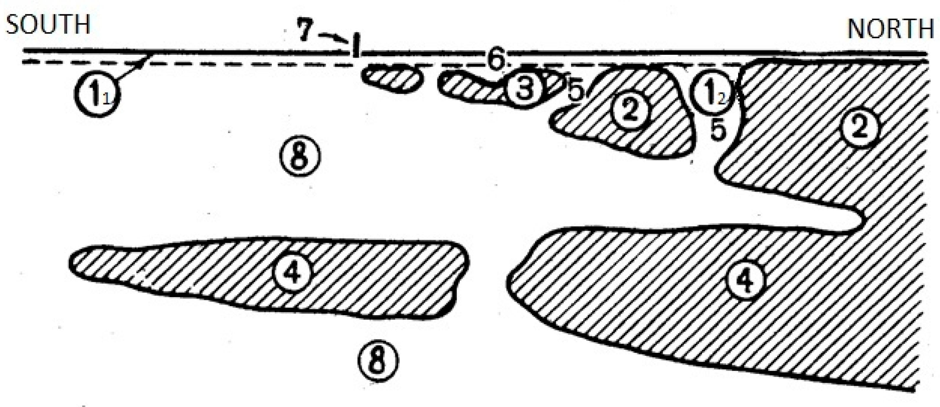
It was revealed that permafrost conditions can be very different even at nearby fields. In the north of West Siberia, permafrost rock intervals can be encountered at different depths in one location. This is attributed to the presence of ancient (relic) permafrost rock depth intervals at the south border of current spreading permafrost (Figure 1).
It is also important to determine at what stage of permafrost layer development the gas production region is currently: aggradation or degradation. This could be obtained through geothermal gradient measurement in observation wells (Figure 2). When the freezing front moves down, the temperature gradient below it is considerable due to quick (in geologic timescale) chilling of the geological section. Chilling flow from the Earth’s surface is stronger than natural heat flow from Earth entrails. At the same time, the freezing of pore water at the front level causes additional heat generation, so we can see a heat “wave” (Figure 2A). But when permafrost thaws from below and the natural heat flow is stronger than the chilling flow, ice-containing rocks at the permafrost bottom require large heat energy for thawing due to the heat of the water phase transition. This heat consumption at the permafrost low border holds the temperature in rocks close to 0 °C for a considerable depth interval (Figure 2B).
The stage of permafrost development is needed for prediction of the natural temperature change of the surrounding rock massif when the production well is under long-time operation and the thawed radius is predicted.
The ice content of permafrost rocks and its distribution with depth are some of the most important parameters of permafrost. Ice can be disseminated in the pore space and be invisible, it can be represented by small visible inclusions in dispersed rocks (cryostructures, Figure 3), or it can form buried large ice bodies in geological sections [22,23,24].
The greatest pore ice content is usually in the upper subsurface rocks and decreases down the geological section. The largest ice content is documented in clays and loams (pore ice content more than 90%, rock volume ice content of 20–80%) [21].
Large ice bodies in geological sections can be represented by buried ice layers remaining after ancient areal deglaciation, by pingo ice (ice core of pingoes), or by developing wedge ice (Figure 4).
The great ice content in subsurface-dispersed rocks leads to the development of quick thermokarst (surface subsidence caused by ice thawing) and thermoerosion (ravine formation caused by warm water flow) processes if any temperature changes on the permafrost surface (Figure 5). Temperature changes are often caused by human-made damage to the plant (in summer) and snow (in winter) layers. Such damage affects the metastable heat exchange regime between the atmosphere and soil, increasing or decreasing the depth of the seasonal thawing/freezing layer. The change in this layer thickness causes a change in seasonal surficial water drainage intensity, especially in tundra areas, and this is the main reason of the fast development of surface geocryological processes. These processes can change the landscape of considerable area in 1–2 years.
Special attention has to be addressed to intrapermafrost natural gas and gas hydrate accumulations during the drilling and operation of wells. Permafrost is not impermeable to natural gas [25]. Gas inside the permafrost has different geneses. It can be local or microbial. It can be thermogenic, originate from greater depths, and sometimes originate from productive horizons. It can be generated in coal or gas shale deposits and it can finally be represented by air buried during surface geologic processes [26]. The dominant gas inside permafrost is methane, but some other light hydrocarbon gases as well as nitrogen and carbon dioxide are often represented in small volumes. Permafrost is not a geologically stable phenomenon: it changes with time, and pressure/temperature changes inside permafrost sections can result in hydrate formation and preservation, so permafrost can be saturated by relic gas hydrates from the first meters of depth [27]. Moreover, all-side rock massif freezing in pingo formation can result in sudden water–gas blowouts with the formation of considerable craters on the day surface (Figure 6).
Favorable conditions for hydrate formation appear at the lower border of thick permafrost (permafrost thickness more than 270 m for methane hydrate) (Figure 7). So, stable hydrates can be encountered at lower parts of the permafrost as well as below its lower border.
Thus, permafrost regions have considerable differences to unfrozen ones. Permafrost is not a stable natural system: it constantly changes under natural and human-made impact. It has a complex structure and is often very reactive due to special properties of frozen rocks based on the presence of ice, gas, and gas hydrate in permafrost sections.
3. Drilling and Production Problems and Their Reasons
3.1. Drilling
One of the first serious problems during well drilling operations is the instability of the upper, ice-saturated ground layer in the summer period. Sand pillows of a few meters in height have to be poured preliminarily on the location of a future well cluster to maintain the safety of the drilling rig and production wells for many years (Figure 8), or an artificial ramp has to be installed [29,30]. Such a pillow prevents seasonal thawing layer formation below the drilling rig and stabilizes permafrost. One more threat for drilling and production operations in the Arctic lowlands is springtime water flooding (Figure 9), which can prevent access to the drilling plot. Thus, sand pillows are needed not only for drilling plots but also for roads.
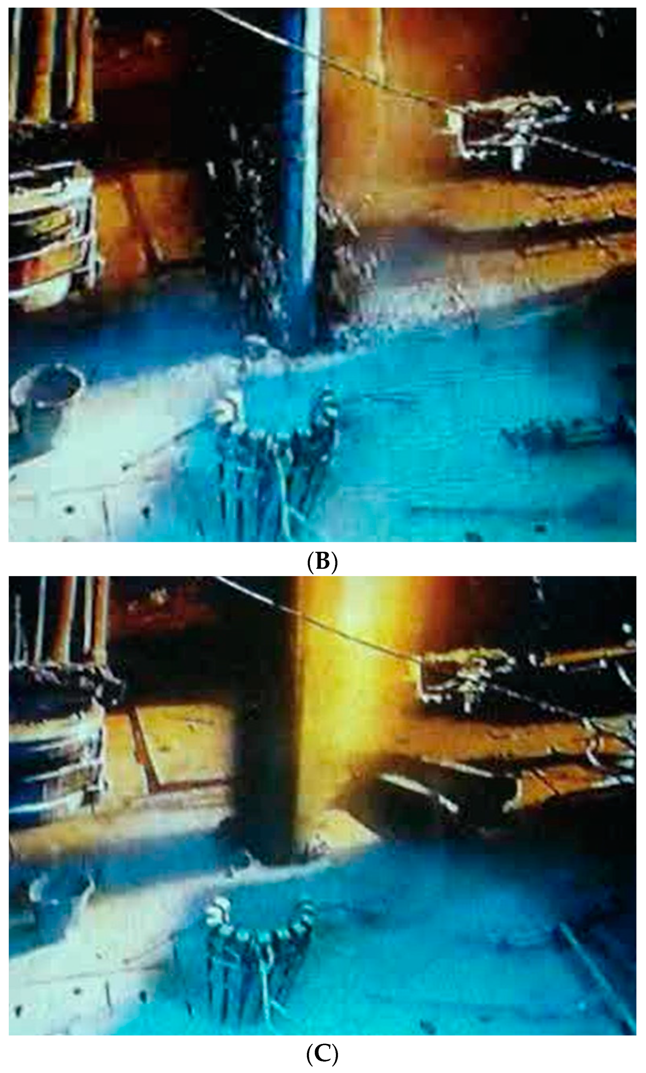
After drilling starts, the next serious problem is sudden gas blowouts from shallow permafrost (depth 5–200 m, Figure 10). Such blowouts have different intensities and duration. They sometimes result in the throwing out of drilling mud and even drilling tubes from the borehole. They are caused by drilling bit penetration through gas and gas–gas hydrate accumulations in shallow permafrost [25]. Intrapermafrost gas and gas hydrate accumulations are in pressure equilibrium with the surrounding strata, but drilling opens a path to the surface for gas, and if warm dill mud is used, hydrates begin to decompose, increasing gas pressure.
These are the most dangerous problems when drilling in permafrost regions. There can be less dangerous problems such as the underdeposition of cement mortar (top of cement below designed depth) and the washing out of the wellhead plot. These problems are attributed to low mechanical properties of permafrost rocks, leading to the shallow hydraulic fracturing of these rocks by drill mud or cement mortar. Fast permafrost rocks thawing around the drill hole can also be a reason of such a phenomenon.
3.2. Production
Sometimes, after completion, the production well remains for a certain period before the start of production. If it is filled by low-mineralized water solution, back freezing in the permafrost depth interval can result in solution freezing inside the annular space and in tubing damage due to the great freezing pressure generated in the closed volume. The same can occur with the casing if freezing of the remaining drill mud occurs. Usually, it remains in cavities after cementing. This freezing is caused by cold flow from the surrounding permafrost. Few production wells were lost at the initial stage of development of the West Siberian gas fields due to undercounting of this phenomenon [10].
The next problem that occurs at all gas wells in permafrost regions is wellhead site surface subsidence (Figure 11). It is caused by permafrost rock contraction when thawing around working wells. This contraction is caused by a difference in ice and water-specific volumes from one side (specific volume of ice is 9% more than that of liquid water) and a decrease in pore size in thawed rocks due to the reduction in compression strength. The deformation of all sediments along the well column is summarized in the surface wellhead area subsidence. Rock thawing continues throughout well operation (tens of years), and such sinkholes appear in each year of production. These sinkholes around wellheads are filled with water in the springtime, accelerating the thawing of permafrost rocks around the well. If no preventative measures exist, the well column can be deformed by its own weight and a wellhead can occur underground (Figure 12).
The thawing radius of the permafrost rock massif around a gas well producing warm gas from a reservoir below the permafrost grows with production time. So, intrapermafrost gas and gas hydrate accumulations can be included in the thawed rock volume. This results in new gas liberations and the formation of gas blowouts behind casings during gas production. These gas liberations become visible in the springtime, when water fills sinkholes around wellheads (Figure 13). These gas liberations create threats of fire and operating personnel poisoning during well inspection. The majority of these liberations are generated inside permafrost, but some originate from deeper productive horizons through channels formed in cementing rings [16].
Thus, production problems are not so visible like drilling problems, but they are not less dangerous. Well column deformation can lead to column breaking, an increase in sinkholes around wellheads, and an acceleration of well deformation, making it difficult for well inspection. Gas liberations from behind-the-casing space can result in fire and personnel poisoning.
4. Engineering Methods of Natural Gas Production Well Protection
Methods of well protection are represented lower according to the problems they solve.
4.1. Back Freezing
This problem has been solved easily: by changing some technical requirements for displacement drill mud salinity and well expectation time period. The displacement drill mud salinity (CaCl2 or NaCl2 content) has to be no lower than 10% mass, providing a freezing temperature of −7 °C, which is usually enough to keep the mud unfrozen at the natural permafrost temperature [31]. The expectation time for the start of operation after well completion and testing usually has to not be longer than 2 weeks, which is enough to prevent back freezing.
4.2. Sudden Gas Blowouts and Gas Liberations from Intrapermafrost Gas and Gas Hydrate Accumulations
Unfortunately, there are no reliable geophysical methods of intrapermafrost gas and gas hydrate accumulation detection currently. Shallow seismic surveys can give some information about possible gas accumulation in permafrost (“bright spots” [32]), but hydrate-containing sediments have practically identical physical properties such as ice-containing ones, so there are no field methods to separate them in geological sections but drilling and coring [33]. Recently, some new data about complex simultaneous measurements of different geophysical parameters in hydrate-bearing frozen rocks have appeared [34]. They give hope that the needed geophysical tool will be developed in the future, but there is currently no working borehole probe to identify gas hydrates in permafrost. So, there is only one method of sudden gas blowout prevention during production well drilling—preliminary drilling of slim shallow degassing wells at the locations of future gas production well clusters, usually 2–3 wells for one well cluster plot. This method is being applied currently at new gas fields on Yamal peninsula (north of West Siberia) and has given positive results (Figure 14), although not each time.
4.3. Wellhead Mechanical Stabilization in Thawing Permafrost
If the production well works for a while and there is well-site subsidence caused by permafrost thawing and compaction, there are two methods of wellhead stabilization: the seasonal pouring of sand to the formed failure and mechanical beam installation. The choice of the method depends on the complexity of geocryological conditions at the gas field. If the upper layers of permafrost are represented by sandy sediments with low ice content and there is no threat of surficial cryogenic processes development around the well, simple sand pouring from a track into the sinkhole is applied each year in the spring/summertime. But if the upper layers of permafrost are represented by ice-saturated sediments, especially by silts, loams, and clays, which lose their mechanical strength considerably when thawing, the installation of long beams is applied (Figure 15).
But seasonal natural ground thawing and wellhead site thawing caused by heat from well operation can cause the thawing radius to grow far from the wellhead and piles under the supporting beam can occur inside this radius. To avoid such a situation, special seasonal cooling devices (SCDs) around piles are applied (Figure 16). Seasonal cooling devices (SCDs, or thermosiphons or thermostabilizers) are freezing elements accumulating cold in the surrounding ground in the wintertime so much that the ground cannot be thawed in the short summer period.
The most complex situation is when a well is designed for operation in unstable ice-saturated permafrost rocks. Sometimes, even a light temperature elevation of such rocks can result in wellhead movement and deformation. Significant changes in well construction are needed to stabilize the wellhead. Passive and active heat isolation systems have to be introduced to the well design. Passive heat isolation is usually represented by materials with a low heat conduction coefficient (foams, microfibers, and so on). In Yamal peninsula, vacuum passive heat isolation has been applied. Passive heat isolation requires inner space for its installation. Figure 17 shows a production well design before and after heat isolation installation. Before installation, the inner diameter of the production tube was 168 mm (Figure 17A). After installation, the inner diameter of the production tube is 114 mm (Figure 17B). Heat isolation arrangement causes a decrease in the production tube diameter and results in a strong correction of all the field production designs due to the increase in production well number [9,29].
Active heat isolation is applied when a well is designed for operation in extremely complex geocryological conditions: in ice-saturated, salted clay sediments, which can be liquified when thawed. The main idea of active heat isolation is to accumulate cold in a rock massif around the wellhead in the wintertime to keep it stable in the summertime. The first time such a technology was suggested was in 1992 [35] and represented winter wind—ventilating sinkholes around wellheads, but it was later considerably modified with the application of powerful seasonal cooling devices (SCDs [36,37,38]). This technology includes the drilling of a few shallow (20–30 m) slim wells around the wellhead and the installation of these wells at a few SCDs joined to a common radiator (Figure 18). A radiator is placed aside the wellheads and does not interfere with the work during well inspections. Such a combined (passive and active) construction has been working on production wells in the north of West Siberia for 10 years and has proved its reliability. Practically, there is no thawing around wellheads and the well operates in stable permafrost.
5. Conclusions
Different technical and technological solutions are applied to prevent possible accidents in permafrost regions: zoning of the field area according to the degree of complexity of geocryological conditions and correction of future gas well cluster locations to avoid zones with extremely complex conditions; preliminary degassing of the permafrost zone by shallow slim wells in locations of future production well clusters; mechanical support of unstable production wells; installation of passive and active heat-isolation systems to well construction and inside ground around wellheads. The last 10 years of application of these measures has allowed the reduction in operation costs of gas production and the avoidance of accidents caused by permafrost instability.
Analyzing Russian experience of natural gas production through unstable permafrost rocks following actions are urgently needed each time before drilling and production start at a new field/part of a field:
- Preliminary careful geological engineering survey of the field area to identify the degree of complexity of geocryological conditions in different locations of the area. This survey has to include the drilling of shallow, 100–150 m deep wells with the recovery of frozen drill cores and laboratory study.
- Correction of well cluster positions to avoid zones with extremely complex geocryological conditions.
- Choice of well heat isolation type and well construction in different locations of the area according to geocryological zoning based on the results of geological engineering survey.
- Modeling of heat interaction between operating well and surrounding frozen rock massif to define power of SCD needed for thawing prevention.
- Reservation of location around wellheads for installation of active heat isolation systems.
The successful operation of the first heat-isolated wells in Yamal peninsula allowed the reduction in well operating costs and the reduction in the risk of well failure in unstable permafrost rocks. These constructions are planned for use in future developments in permafrost areas. Moreover, such well constructions with powerful SCDs could help in the development of Arctic oil and gas fields located offshore: the winter freezing of sea water around future wellheads by SCDs can prepare artificial marine ice islands frozen to the seafloor and represent a convenient area for hydrocarbon exploration and production operations all around the year [39].
Funding
Funding for this study was provided by the special Scientific Foundation of Gubkin University.
Institutional Review Board Statement
Not applicable.
Informed Consent Statement
Not applicable.
Data Availability Statement
Not applicable.
Acknowledgments
The author thanks A. B. Osokin, A. P. Popov, and N. R. Avetov for their assistance with the data.
Conflicts of Interest
The author declares no conflict of interest.
References
- Jevons, W.S. The Coal Question: An Inquiry Concerning the Progress of the Nation, and the Probable Exhaustion of Our Coal-Mines, 3rd ed.; Flux, A.W., Ed.; Macmillan: London, UK, 1906. [Google Scholar]
- Okeke, O.C.; Okogbue, C.O. Shales: A review of their classifications, properties and importance to the petroleum industry. Glob. J. Geol. Sci. 2011, 9, 55–73. [Google Scholar]
- Henriksen, N.; Higgins, A.K.; Kalsbeek, F.; Christopher, T.; Pulvertaft, R. Greenland from archaean to quaternary descriptive text to the 1995 geological map of Greenland, 1:2,500,000. 2nd edition. Geol. Surv. Den. Greenl. Bull. 2009, 18, 2–93. [Google Scholar]
- Hoffman, P.F. Precambrian geology and tectonic history of North America. In The Geology of North America—An Overview; Bally, A.W., Palmer, A.R., Eds.; Geological Society of America: Boulder, CO, USA, 1989; pp. 447–511. [Google Scholar]
- Osadetz, K.; Dixon, J.; Dietrich, J.; Snowdon, L.; Dallimore, S.; Majorowicz, J. A review of Mackenzie Delta-Beaufort Sea petroleum province conventional and nonconventional (gas hydrate) petroleum reserves and undiscovered resources: A contribution to the resource assessment of the proposed Mackenzie Delta-Beaufort Sea Marine Protected Areas. Geol. Surv. Canad. Open File 2005, 4828, 31. [Google Scholar]
- Raynolds, M.K.; Walker, D.A.; Ambrosius, K.J.; Brown, J.; Everett, K.R.; Kanevskiy, M.; Kofinas, G.P.; Romanovsky, V.E.; Shur, Y.; Webber, P.J. Cumulative geoecological effects of 62 years of infrastructure and climate change in ice-rich permafrost landscapes, Prudhoe Bay Oilfield, Alaska. Glob. Chang. Biol. 2014, 20, 1211–1224. [Google Scholar] [CrossRef]
- Biskaborn, B.K.; Smith, S.L.; Noetzli, J.; Matthes, H.; Vieira, G.; Streletskiy, D.A.; Schoeneich, P.; Romanovsky, V.E.; Lewkowicz, A.G.; Abramov, A.; et al. Permafrost is warming at a global scale. Nat. Commun. 2019, 10, 264. [Google Scholar] [CrossRef] [Green Version]
- Andreev, O.F.; Kolushev, N.R. Problems of wells and production facilities operation realiabiliry providing in cryolithozone. In Peculiarities of Gas Fields Development in Complex Geocryoloigic Conditions; Andreev, O.F., Kolushev, N.R., Eds.; Gazprom VNIIGAZ: Moscow, Russia, 1987; pp. 4–7. (In Russian) [Google Scholar]
- Byunau, Y.K.; Borisov, V.B.; Ploskov, A.A.; Zakharov, M.I. Methodical and Instrumental Measurement Providing of Thermophysical Charackterisics of Heat-Isolated Lift and Tubing Strings; Gazprom VNIIGAZ: Moscow, Russia, 2012; p. 48. (In Russian) [Google Scholar]
- Vrachyev, V.V.; Antipov, V.I.; Podolyako, M.I. Calculation of radial loading on casing at Urengoy gas field conditions. In Peculiarities of Gas Fields Development in Complex Geocryoloigic Conditions; Andreev, O.F., Kolushev, N.R., Eds.; Gazprom VNIIGAZ: Moscow, Russia, 1987; pp. 68–79. (In Russian) [Google Scholar]
- Bogoyavlensky, V.I. Natural and technogenic threats in fossil fuels production in the Earth cryolithosphere. Russ. Min. Ind. 2020, 97–118. (In Russian) [Google Scholar] [CrossRef] [Green Version]
- Yakushev, V.S. One of possible reasons of sudden gas blowouts in permafrost rock massifs. Geol. Oil Gas 1989, 4, 45–46. (In Russian) [Google Scholar]
- Bogoyavlensky, V.I.; Bogoyavlensky, I.V.; Nikonov, R.; Kishankov, A. Complex of Geophysical Studies of the Seyakha Catastrophic Gas Blowout Crater on the Yamal Peninsula, Russian Arctic. Geosciences 2020, 10, 215. [Google Scholar] [CrossRef]
- Chuvilin, E.; Sokolova, N.; Davletshina, D.; Bukhanov, B.; Stanilovskaya, J.; Badetz, C.; Spasennykh, M. Conceptual models of gas accumulation in the shallow permafrost of Northern West Siberia and conditions for explosive gas emissions. Geosciences 2020, 10, 195. [Google Scholar] [CrossRef]
- Kraev, G.; Rivkina, E.; Vishnivetskaya, T.; Belonosov, A.; van Huissteden, J.; Kholodov, A.; Smirnov, A.; Kudryavtsev, A.; Teshebaeva, K.; Zamolodchikov, D. Methane in Gas Shows from Boreholes in Epigenetic Permafrost of Siberian Arctic. Geosciences 2019, 9, 67. [Google Scholar] [CrossRef] [Green Version]
- Yakushev, V.S. Natural Gas Liberations around Production Wells at Russian Arctic Gas Fields. Geosciences 2020, 10, 184. [Google Scholar] [CrossRef]
- Kudryavtsev, V.A. General Permafrostology (Geocryology), 2nd ed.; Moscow State University: Moscow, Russia, 1978; p. 464. (In Russian) [Google Scholar]
- Ershov, E.D. General geocryology. In Manual for High School; Cambridge University Press: Cambridge, UK, 2002; p. 682. [Google Scholar]
- Dobrinski, W. Permafrost. Earth-Sci. Rev. 2011, 108, 158–169. [Google Scholar] [CrossRef]
- STO Gazprom 2-3.1-233-2008; The Technique of Geocryologic Survey Conduction When Gas Fields Exploration and Development. IRC Gazprom: Moscow, Russia, 2008; p. 115. (In Russian)
- Yakushev, V.S. Gas and Gas Condensate Fields Development at Complicated Geocryological Conditions; Gubkin University: Moscow, Russia, 2014; p. 188. (In Russian) [Google Scholar]
- Tsytovich, N.A. Mechanics of Frozen Rocks, 2nd ed.; LIBROCOM Public: Moscow, Russia, 2010; p. 448, Reprinting of textbook 1974. (In Russian) [Google Scholar]
- Penner, E. Aspects of ice lens growth in soils. Cold Reg. Sci. Technol. 1986, 13, 91–100. [Google Scholar] [CrossRef] [Green Version]
- Ershov, E.D.; Lebedenko, Y.P.; Chuvilin, E.M.; Yazynin, O.M. Microstructure of Frozen Rocks; Moscow State University: Moscow, Russia, 1988; p. 183. (In Russian) [Google Scholar]
- Yakushev, V. Natural Gas and Gas Hydrates in Cryolithozone; Gazprom VNIIGAZ: Moscow, Russia, 2009; p. 192. (In Russian) [Google Scholar]
- Yakushev, V. Genetic types of hydrocarbon gases in permafrost. Earth’s Cryosphere 2015, 3, 71–76. (In Russian) [Google Scholar]
- Yakushev, V.S.; Chuvilin, E.M. Natural gas and gas hydrate accumulations within permafrost in Russia. Cold Reg. Sci. Technol. 2000, 31, 189–197. [Google Scholar] [CrossRef]
- Bogoyavlensky, V.; Mazharov, A.; Pushkarev, V.; Bogoyavlensky, I. Gas emissions from the Yamal peninsula permafrost areas. Preliminary results of the expedition dated 8th July 2015. Drill. Oil 2015, N 07-08, 8–13. (In Russian) [Google Scholar]
- Yakushev, V.S. Permafrost Impact on Gas Fields Development in the Russian Onshore Arctic (Yamal Peninsula). In Proceedings of the OTC Arctic Technology Conference, Copenhagen, Denmark, 23–25 March 2015. Paper Number: OTC-25504-MS. [Google Scholar]
- Schoderbek, D.; Boswell, R. Iġnik Sikumi Gas Hydrate Field Trial Completed. Fire Ice Methane Hydrate Newsl. 2012, 12, 1–3. [Google Scholar]
- Recommendations on Well Drilling in Frozen Rocks at Geological Engineering Survey for Construction; PNIIIS Stroyizdat: Moscow, Russia, 1974; p. 81. (In Russian)
- Dallimore, S.; Chuvilin, E.M.; Yakushev, V.S. Natural gas in permafrost of northern Canada and Russia: Genesis and forms of existence. In Proceedings of the Materials of the 2nd Conference of Russian Geocryologists, Moscow, Russia, 6–9 June 2001; Volume 2, pp. 289–294. [Google Scholar]
- Yakushev, V.; Gafarov, N.; Karnaukhov, S.; Rybalchenko, V.; Ogorodnikov, I. Gas Hydrates in Arctic and World Ocean: Peculiarities of Occurence and Prospects of Development; Nedra Publisher: Moscow, Russia, 2014; p. 251. (In Russian) [Google Scholar]
- Farahani, M.V.; Hassanpouryouzband, A.; Yang, J.; Tohidi, B. Development of a coupled geophysical–geothermal scheme for quantification of hydrates in gas hydrate-bearing permafrost sediments. Phys. Chem. Chem. Phys. 2021, 23, 24249–24264. [Google Scholar] [CrossRef]
- Yakushev, V.S. System of wellhead heat isolation in permafrost regions. Gas Ind. 1992, 6, 13–15. (In Russian) [Google Scholar]
- Kononov, V.I.; Berezniyakov, A.I.; Smolov, G.K.; Zabelina, L.S.; Olinevitch, G.V.; Popov, A.P.; Osokin, A.B. The Way of Well Head Zone Heat State Stabilization in Permafrost. Rocks. Patent RU 2158353 C1, 27.10.2000, 3 October 1999. [Google Scholar]
- Melnikov, V.P.; Nersesov, S.V.; Osokin, A.B.; Nikolaichuk, E.V.; Vasil’yeva, A.O.; Mikhalchenko, D.I. Geotechnical solutions for gas production wells construction at very complex geocryologic conditions. Gas Ind. 2019, 12, 64–71. (In Russian) [Google Scholar]
- Osokin, A.B.; Afonin, A.S.; Vasilyeva, A.O.; Nikolaychuk, E.V.; Pakhunov, A.V. Ensuring the stability of production wells during the development of Neocom-Jurassic deposits of the Bovanenkovskoye and Kharasaveyskoye fields. In Proceedings of the “Monitoring in Cryolithozone”. Materials of the 6th Conference of Russian Geocryologists, Moscow, Russia, 14–17 June 2022; Motenko, R.G., Ed.; Moscow State University: Moscow, Russia, 2022; pp. 816–825. Available online: https://bookonlime.ru/node/44945 (accessed on 29 May 2023). (In Russian).
- Yeliseyev, A.A.; Yakushev, V.S. Successful experience of wellhead heat isolation at Yamal gas fields as prologue of new technologies for Kara sea gas fields development. Sci. J. Russ. Gas Soc. 2021, 31, 30–33. (In Russian) [Google Scholar]
Figure 1.
Scheme of permafrost geological section in the North of West Siberia [17]. 11—Seasonal freezing layer; 12—seasonal thawing layer; 2—current continuous permafrost; 3—current discontinuous permafrost; 4—ancient (relic) continuous and discontinuous permafrost; 5—open taliks; 6—closed taliks; 7—current south border of permafrost spreading; 8—unfrozen rocks.

Figure 2.
Temperature distribution with depth with permafrost aggradation (A) and degradation (B). H—depth, t—temperature (°C) [21].
Figure 2.
Temperature distribution with depth with permafrost aggradation (A) and degradation (B). H—depth, t—temperature (°C) [21].

Figure 3.
Cryostructure types in frozen rocks (according to Tsytovich, 1974 [22]). (a) Continuous (massive), (b) layered (lens-like), (c) cell-like.
Figure 3.
Cryostructure types in frozen rocks (according to Tsytovich, 1974 [22]). (a) Continuous (massive), (b) layered (lens-like), (c) cell-like.

Figure 4.
Polygonal-wedge ice network around pingo hill with thermokarst processes development. Rock polygons were formed by frost cracking of ice-saturated surface rocks. Cracks between polygons were filled by water in the summertime. In the wintertime, the water froze [21].
Figure 4.
Polygonal-wedge ice network around pingo hill with thermokarst processes development. Rock polygons were formed by frost cracking of ice-saturated surface rocks. Cracks between polygons were filled by water in the summertime. In the wintertime, the water froze [21].

Figure 5.
Buried ice body thawing (thermokarst) at Yamal peninsula (North of West Siberia, photo by A. B. Osokin). Technogenic impact caused tundra surface thawing and the occurrence of a partially naked ice body that started to thaw more faster than the surrounding ground, forming a thermokarst lake.

Figure 6.
“Ice crater” with diameter of about 30 m in Yamal peninsula tundra (Photo by Bogoyavlensky [28]).
Figure 6.
“Ice crater” with diameter of about 30 m in Yamal peninsula tundra (Photo by Bogoyavlensky [28]).

Figure 7.
Methane hydrate stability zone and hydrate metastability zone in geological section with permafrost (inside cryolithozone) [25]. 1—Methane hydrate formation equilibrium curve; 2—Natural temperature/pressure distribution in geologic section.
Figure 7.
Methane hydrate stability zone and hydrate metastability zone in geological section with permafrost (inside cryolithozone) [25]. 1—Methane hydrate formation equilibrium curve; 2—Natural temperature/pressure distribution in geologic section.

Figure 8.
Sand pillow for drilling rig and well cluster in the North of West Siberia [29].
Figure 8.
Sand pillow for drilling rig and well cluster in the North of West Siberia [29].

Figure 9.
Springtime waterflooding around well cluster plot in the North of West Siberia (photo by A. P. Popov).
Figure 9.
Springtime waterflooding around well cluster plot in the North of West Siberia (photo by A. P. Popov).

Figure 10.
Gas blowout from permafrost when drilling (photos from mobile phone movie, first time publishing). (A) Before the start of blowout; (B) 1 min after the start (dill mud blowout); (C) 2 min after the start (gas–mud mixture blowout).
Figure 10.
Gas blowout from permafrost when drilling (photos from mobile phone movie, first time publishing). (A) Before the start of blowout; (B) 1 min after the start (dill mud blowout); (C) 2 min after the start (gas–mud mixture blowout).


Figure 11.
Typical spring well-site surface subsidence around working gas well [21].
Figure 11.
Typical spring well-site surface subsidence around working gas well [21].

Figure 12.
Surface subsidence and wellhead movement caused by permafrost thawing around gas production well (Zapolyarnoye gas field, West Siberia [9]).
Figure 12.
Surface subsidence and wellhead movement caused by permafrost thawing around gas production well (Zapolyarnoye gas field, West Siberia [9]).

Figure 13.
Gas liberations from permafrost around working well at Yamburg gas field (Yellow circles—locations of gas liberations, photo by N. R. Avetov).
Figure 13.
Gas liberations from permafrost around working well at Yamburg gas field (Yellow circles—locations of gas liberations, photo by N. R. Avetov).

Figure 14.
Permafrost and hydrate-stability zone degassing before production well drilling [29].
Figure 14.
Permafrost and hydrate-stability zone degassing before production well drilling [29].

Figure 15.
Strengthening the wellhead by long steel beam in unstable permafrost [16].
Figure 15.
Strengthening the wellhead by long steel beam in unstable permafrost [16].

Figure 16.
Wellhead support with seasonal cooling devices (SCDs) around piles keeping ground frozen all year round [21].
Figure 16.
Wellhead support with seasonal cooling devices (SCDs) around piles keeping ground frozen all year round [21].

Figure 17.
Section of first design of production well without heat isolation (A) and final design (B) after introduction of passive heat isolation [29]. Numbers above the picture indicate tube diameter in mm; 800 means outer diameter of a hole for the first casing tube. Cenomanian and Aptian—gas production horizons.

Figure 18.
Placement of SCD tubes in ground around wellhead (A) and heat-isolated well cluster before start of production (B). The general radiator of the chilling system is visible behind the wellheads [21].
Figure 18.
Placement of SCD tubes in ground around wellhead (A) and heat-isolated well cluster before start of production (B). The general radiator of the chilling system is visible behind the wellheads [21].

Disclaimer/Publisher’s Note: The statements, opinions and data contained in all publications are solely those of the individual author(s) and contributor(s) and not of MDPI and/or the editor(s). MDPI and/or the editor(s) disclaim responsibility for any injury to people or property resulting from any ideas, methods, instructions or products referred to in the content. |
© 2023 by the author. Licensee MDPI, Basel, Switzerland. This article is an open access article distributed under the terms and conditions of the Creative Commons Attribution (CC BY) license (https://creativecommons.org/licenses/by/4.0/).
Share and Cite
MDPI and ACS Style
Yakushev, V. Environmental and Technological Problems for Natural Gas Production in Permafrost Regions. Energies 2023, 16, 4522. https://doi.org/10.3390/en16114522
AMA Style
Yakushev V. Environmental and Technological Problems for Natural Gas Production in Permafrost Regions. Energies. 2023; 16(11):4522. https://doi.org/10.3390/en16114522
Chicago/Turabian StyleYakushev, Vladimir. 2023. "Environmental and Technological Problems for Natural Gas Production in Permafrost Regions" Energies 16, no. 11: 4522. https://doi.org/10.3390/en16114522
Note that from the first issue of 2016, this journal uses article numbers instead of page numbers. See further details here.