Article

Effect of Leading/Trailing Edge Swept Impeller on Flow Characteristics of Low Specific Speed Centrifugal Compressor

1
State Key Laboratory of Reliability and Intelligence of Electrical Equipment, School of Mechanical Engineering, Hebei University of Technology, Tianjin 300401, China
2
National Key Laboratory of Diesel Engine Turbocharging Technology, China North Engine Research Institute, Tianjin 300400, China
*
Authors to whom correspondence should be addressed.
Energies 2023, 16(11), 4286; https://doi.org/10.3390/en16114286
Submission received: 29 April 2023 / Revised: 20 May 2023 / Accepted: 22 May 2023 / Published: 24 May 2023

Abstract

:
A low specific speed centrifugal compressor with leading/trailing edge combined sweep blades is proposed. The performance and internal flow field characteristics are analyzed in detail by numerical simulations, and a bench test is carried out. It is shown that by using the combined leading/trailing edge swept blade, the stage pressure ratio of the centrifugal compressor is improved under all operating conditions, and the maximum increase can reach 6.5%. The efficiency can be markedly improved at high flow rates. Additionally, the leading edge tip leakage is reduced with the combined swept blade, the flow separation on the blade surface is inhibited, and the flow loss of low-energy flow masses downstream of the flow passage is improved. Meanwhile, the combined swept blade can increase the work area of the blade and enhance the work capacity at the blade tip position.

1. Introduction

Energy shortage is an urgent problem to be solved in the world. One of the high potential alternative power sources for future vehicles is fuel cells, with which vehicles can use hydrogen as fuel, making zero emissions. The fuel cell air compressor is a critical component of a fuel cell system, which compresses and delivers oxygen to the fuel cell stack in order to promote electrochemical reactions and generate electricity. A low specific speed centrifugal compressor is usually used in the fuel cell air systems, which compress gas to reach two or four times that of the ambient pressure. A good low specific speed centrifugal compressor can improve the efficiency and water balance performance of the fuel cell system [1]. However, due to low temperature and pressure of fuel cell exhaust gas, the centrifugal compressor can be driven only by a motor [2], so the special design of the low specific speed centrifugal compressor is particularly important.
Many factors affect the performance of centrifugal compressors, including inlet pipes, number of blades, tip clearance, diffuser and volute, etc. [3,4,5,6,7,8]. As the main work element of the compressor, the modeling design of the impeller blade directly affects the working performance of the compressor. Controlling geometric parameters such as blade bending, sweeping, and inclination is a common method for blade modification [9,10,11]. Research shows that backward bending blades can improve the flow condition in the wake region, enhance the flow capacity, and increase the efficiency of the compressor [9]. Various blade lean angles can change the shock wave intensity, the wake region range, and the structural characteristics of the impeller [10]. In addition, by varying the sweep angle, the load distribution of the blade can be improved and the shock wave structure and migration of low-energy fluids can be controlled [11].
Blade swept technology is an important improvement method for compressors’ performance. It influences the tip flow field by changing tip geometry and has been widely used in axial compressors. A detailed analysis of the rotor flow field of an axial compressor was carried out by Hah et al. [12], which shows that blade swept technology can improve the flow structure in the tip region and increase compressor performance by controlling the shock wave structure and secondary flow migration in the passage. Meanwhile, Govardhan et al. [13] pointed out the backward swept rotor can promote the accumulation of low-energy fluid and enlarge the flow separation range at the tip, which adversely affects stall margin. Cui et al. [14] further revealed the interrelation between sweep and variety of flow fields by using numerical methods. The radial pressure gradient generated by the forward sweep weakened the migration of low-energy fluid, which reduced the shock wave intensity in the tip and drove the shock wave to move upstream. Additionally, the forward sweep method inhibited the strength of the leakage flow as a result of a reduction in the rotor leading edge load.
For the centrifugal impeller, leading edge sweep can also play an important role. The effects of leading edge swept angle varying from −20° to +25° on the compressor were compared and analyzed by Ganesh et al. [15], who concluded that the compressor with forward sweep of 20° and a tip clearance of 0.5 mm had the best efficiency and stall margin. The mechanisms of leading edge sweep were also investigated by He et al. [10]. The forward sweep can reduce the leading edge tip load, weaken the shock wave strength and leakage vortex strength, then decrease the loss at the casing; the backward sweep can reduce the leading edge blade root load, suppress the flow separation, and decrease the loss at the hub. Guo et al. [16] pointed out that the main/splitter blade mixed with forward sweep impeller can weaken the impact of leading edge shock wave and secondary flow, improving flow capacity and working margin of the compressor. Zhao et al. [17] obtained a similar conclusion by studying the effect of leading edge compound sweep and lean on the compressor. Li et al. [18] discovered that the influences of leading edge sweep were closely related to different shock wave shapes at the impeller inlet. Hazby et al. [19] further investigated the effect of free-swept leading edge on compressor performance. Compared with the ordinary swept impeller, the free-swept impeller can improve not only the strength and position of the inlet shock wave but also the structural characteristics. Different conclusions were obtained in compressors with different geometric parameters. Wang et al. [20] found that although backward sweep would increase the local shock range and cause total pressure loss, the appropriate backward sweep angle can improve the efficiency of the compressor. Erdmenger et al. [21] suggested that backward sweep can achieve higher peak efficiency and pressure ratio, while also resulting in a reduced stable operating range. In addition, for the impeller trailing edge at the radial outlet, Hildebrandt et al. [22] indicated that the trailing edge backward sweep makes the outlet velocity and flow angle distribution more uniform, which was beneficial in the diffuser inside flow. Li et al. [23] analyzed the influence of impeller trailing edge sweep and found that backward sweep can improve flow conditions near the trailing edge, but it can cause non-uniform pressure distribution at the outlet and increase downstream losses in the diffuser. Tian et al. [24] studied two types of swept impeller at the trailing edge, incline swept and free swept. They showed that the trailing edge sweep could inhibit the combination of flow separation and leakage flow and increase working range and efficiency of the impeller. Furthermore, the trailing edge free sweep has a larger work area and stronger pressure ratio improvement ability. However, most studies focus on high pressure ratio centrifugal compressors sweeping at the leading or trailing edge; few have investigated sweeping influences on both edges. Tian et al. [25] proposed a developed method of leading/trailing edge free sweep of a transonic centrifugal compressor impeller and found that this impeller can increase the pressure ratio and stability of the compressor by improving the transonic flow at the impeller inlet and the interaction of low-energy flow at the trailing edge. In addition, fewer research studies are carried out on the swept effects on low specific speed centrifugal compressors, with long-narrow impeller passage, high-secondary flow loss, high tip leakage, and a small outlet width. To further understand the complex aerodynamic performance of low specific speed centrifugal compressors, Methel et al. [26] introduced in detail a new test facility called Centrifugal Stage for Aerodynamics Research (CSTAR). Zhang et al. [27] and Kawanishi et al. [28] investigated the geometric characteristics of impeller blades and diffuser blades in low specific speed centrifugal compressors, respectively, and derived the design rules and strategies for enhancing compressor aerodynamic performance. Zhang et al. [29] also conducted research on the low specific speed centrifugal impeller with flow-trimming. In terms of sweep, Wang et al. [30] reported the leading edge forward sweep can reduce the blade load and tip leakage of the main blade of the low specific speed centrifugal impeller, but it showed little improvement in the overall performance of compressor. Xu et al. [31] optimized the outlet meridian shape of centrifugal impeller. They indicated that increasing the tip diameter can improve the work capacity at the shroud, reduce tip leakage and secondary flow loss, and inhibit the flow migration between hub and shroud.
In this paper, mechanisms of swept blade, especially combined swept, on the aerodynamic performance of a low specific speed centrifugal compressor have been numerically investigated. A three-dimensional simulation model has been constructed, and numerical results are discussed in detail. The aerodynamic effects of combined swept blades are analyzed, and the internal flow properties of the compressor are explored. Finally, a bench test is used to verify the developed method of combined swept.

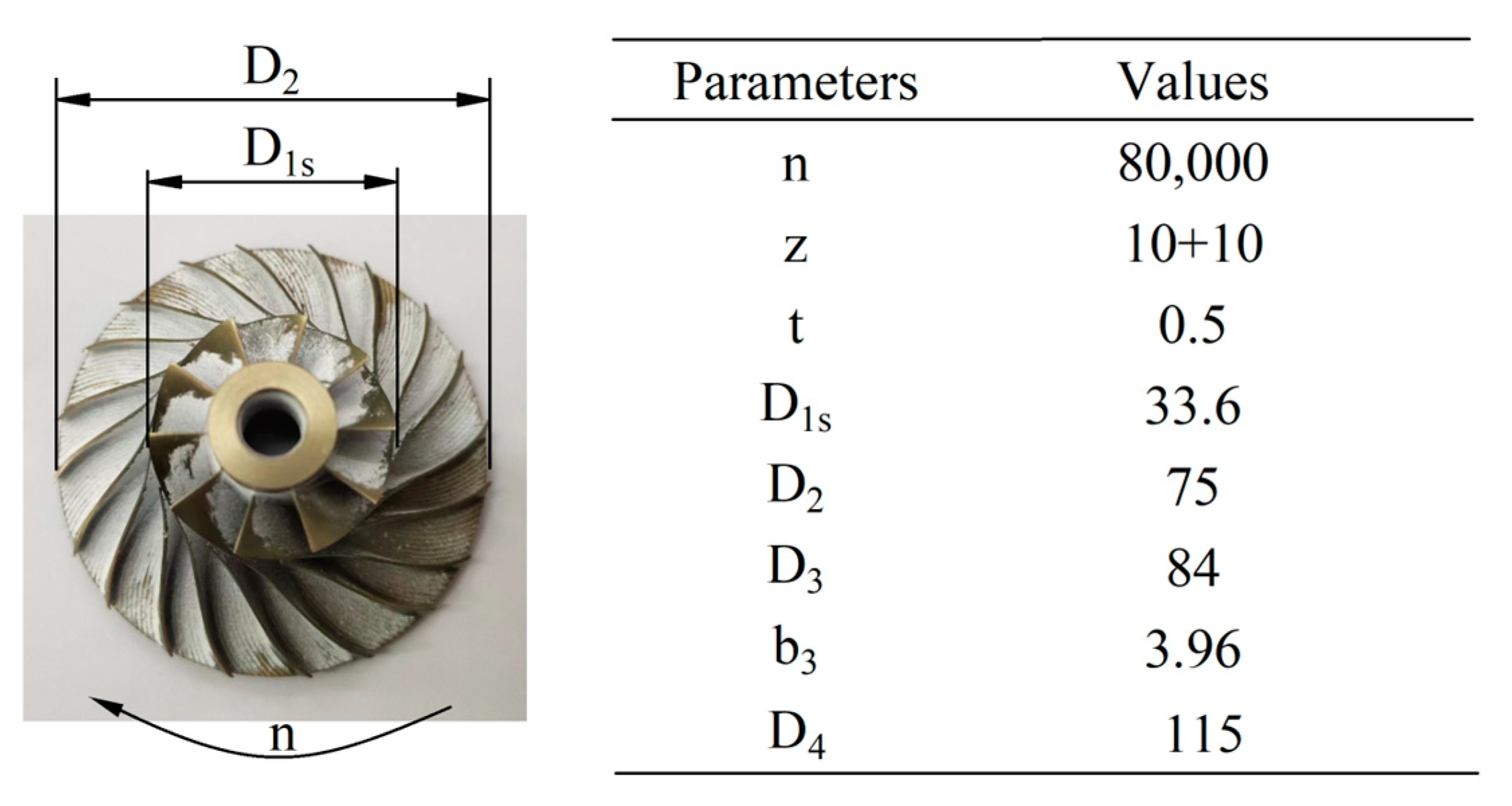
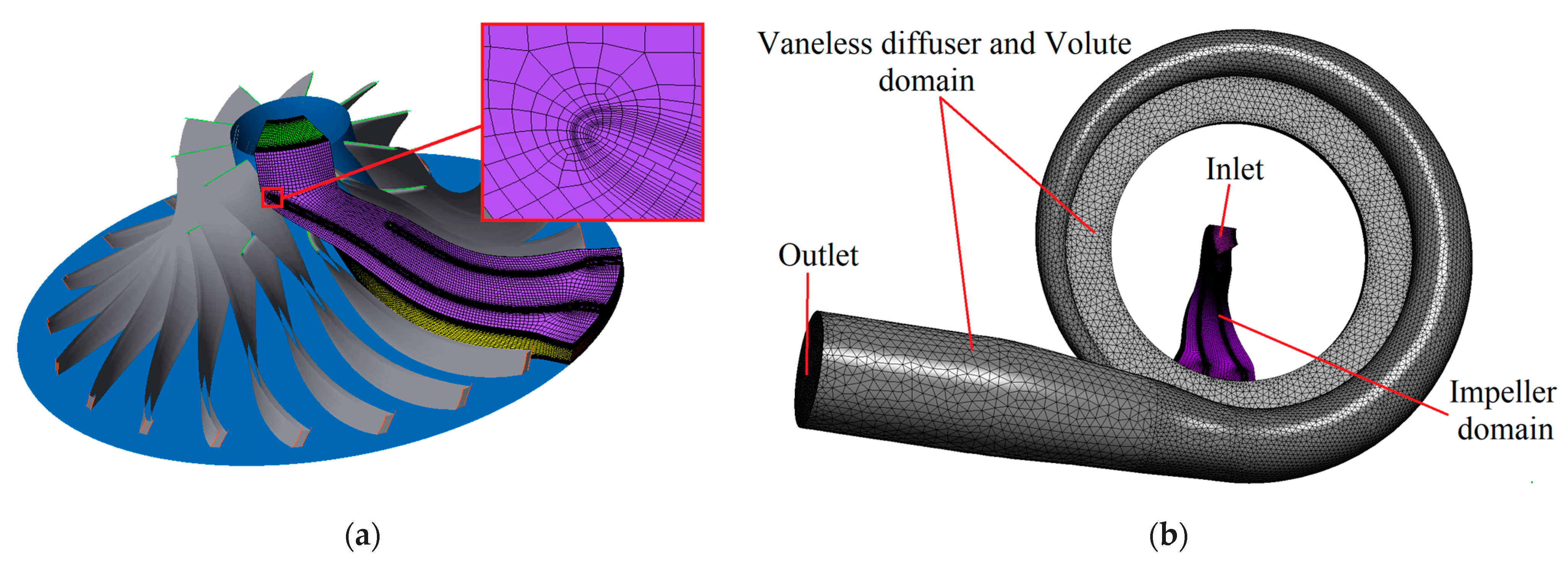
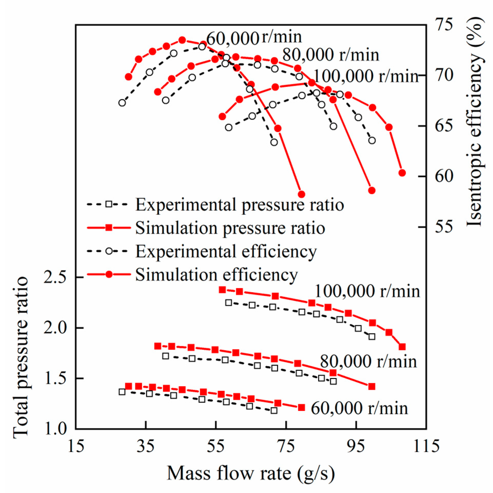
2. Datum Model and Numerical Verification of Compressor

The centrifugal compressor stage is composed of the semi-open impeller with splitter blades, vaneless diffuser, and volute. The basic parameters of the unswept datum of a low specific speed centrifugal impeller and other components are shown in Figure 1.
Three-dimensional steady-state simulation was established by commercial computational fluid dynamics (CFD) software ANSYS CFX to assess the aerodynamic performance of the compressor. The Shear Stress Transport (SST) turbulence model blending with the k-ω model was chosen to close the Reynolds-averaged Navier–Stokes (RANS) equations [32,33]. The first-order upwind scheme difference method and the time integral method of the second-order backward Euler scheme were used. Considering the circumference periodicity flow in the impeller, a sing passage was considered and the periodic boundary conditions were used between adjacent passages. The computational domain consisted of a single impeller blade passage, a vaneless diffuser, and volute. Table 1 shows the boundary conditions of the calculation model. The mixing plane method was adopted at the rotor-stator interface, and all of the solid walls were set as no-slip and adiabatic. Total pressure (101,325 Pa) and total temperature (298 K) were imposed on the compressor inlet, and the flow was uniform axial. At the outlet, the calculation started from near-chock point for each rotation speed and the average static pressure was initially given as mass flow rate when the pressure ratio did not change obviously with the flow rate. The convergence criterion is that the residuals fall below 1.0 × 10⁻⁵. When the pressure ratio obviously decreased or the residual did not converge it was considered as the surge point.
The governing equations of fluid motion comprise the conservation equations for mass, momentum, and energy. This paper aims to solve the Reynolds-averaged Navier–Stokes equations, which are composed of the aforementioned three conservation equations.
ρ t + ρ V = 0
where ρ is the density of the fluid and V is its velocity.
ρ V t + V V = p + τ + ρ f
where p is the pressure, τ is the stress tensor, and f is any external body force acting on the fluid.
t ρ e + 1 2 ρ V 2 = q + ρ V f
where e is the internal energy per unit mass, q is the heat flux, and V f represents the work done by external forces.
The Shear Stress Transport (SST) turbulence model is used in this paper, which comprises two equations: one for k, the turbulent kinetic energy,
k t + U j k x j = P k β * ω k + x j ( ν + σ k ν T ) k x j
and one for ω (omega), the specific dissipation rate:
ω t + U j ω x j = α S 2 β ω 2 + x j ( ν + σ ω ν T ) ω x j + 2 ( 1     F 1 ) σ ω 2 1 ω k x i ω x i
where
ν T = a 1 k max ( a 1 ω , S F 2 ) F 2 = tanh max ( 2 k β * ω y , 500 ν y 2 ω ) 2 P k = min ( τ i j U i x j , 10 β * k ω ) F 1 = tanh min max ( k β * ω y , 500 ν y 2 ω ) , 4 σ ω 2 k C D k ω y 2 4
where
C D k ω = max ( 2 ρ σ ω 2 1 ω k x i ω x i , 10 10 ) ,   a 1 = 5 9 ,       β = 3 40 ,       β * = 9 100 ,     σ ω 2 = 0.856
The impeller part was meshed by hexahedral meshes via Turbogrid. Due to the complexity of the volute geometry, tetrahedral meshes were generated for the diffuser and volute sections using ICEM. In order to meet the requirements of the turbulence model and ensure y+ < 10 (y+ is the dimensionless wall distance), the height of the first layer of mesh near the wall was set at 0.001 mm. The grid convergence index (GCI) method was used to test the grid independence of the computational domain, with three different grid sizes generated (fine, N1; medium, N2; and coarse, N3), corresponding to element numbers ranging from 1,064,226 to 466,021 and 207,537. Following the estimation procedure of discretization uncertainty in CFD application by Celik et al. [34,35,36], the results of numerical uncertainty evaluation are given in Table 2. The results show that the GCI for total pressure ratio and isentropic efficiency in the fine-grid solution are 0.09% and 0.332%, respectively, which meet the convergence standard. Therefore, the fine-grid has ultimately been chosen for subsequent numerical calculations. The centrifugal compressor impeller and stage mesh are shown in Figure 2.
As the baseline compressor, Figure 3 plots the performances of an unswept datum impeller at three rotational speeds by CFD simulation and experimental test. It shows quite a good agreement between them with respect to the tendency of total pressure ratio and efficiency curves. However, some calculation errors are seen between simulation results and experimental test, for the reasons that heat transfer loss is inevitable during experiment and the adiabatic wall is set as the boundary condition in the actual numerical simulation. The numerical method is therefore considered capable of predicting the compressor performance and the flow details at surge point, choke point, and maximum efficiency point of the compressor.

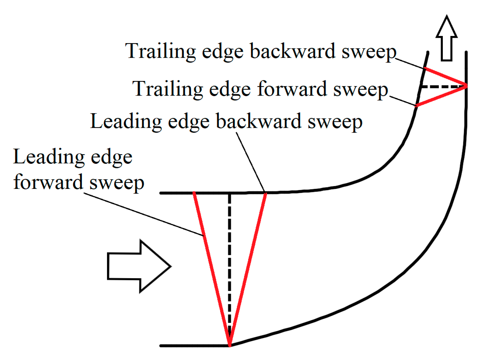
3. Definition of Combined Sweep Blades

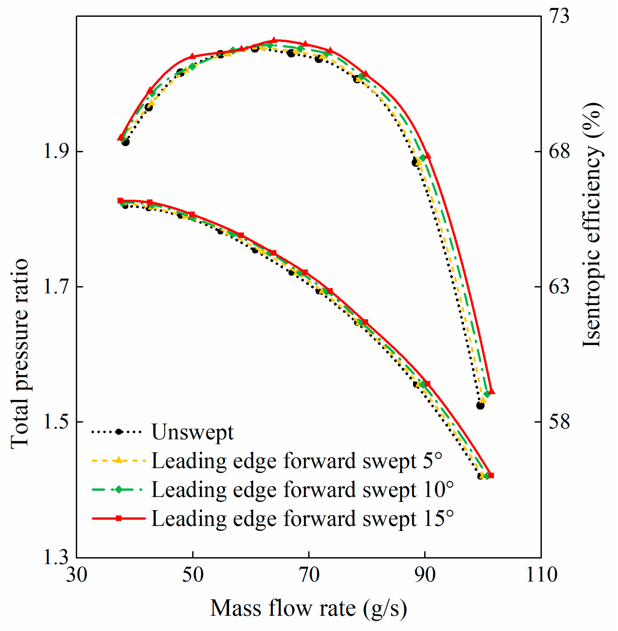
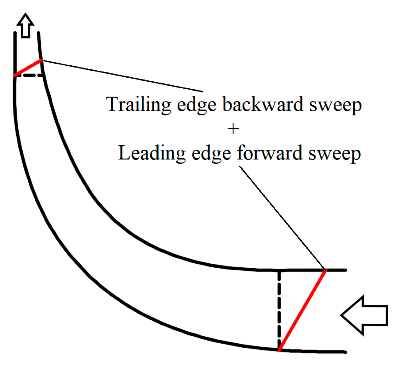
3.1. Swept Analysis at Leading Edge, Trailing Edge, and Both Edges

Three kinds of swept impellers have been investigated: sweeping at leading edge, sweeping at trailing edge, and sweeping at both edges of the impeller. The meridional shapes of swept impellers based on that of the datum impeller are shown in Figure 4. The blade is forward swept in the direction of incoming flow; otherwise, it is backward swept.
The effect of swept impeller at leading edge on compressor performance is shown in Figure 5. Compared with the unswept datum impeller, the total pressure ratio and efficiency of the forward swept impeller are slightly improved within the operating range. For the backward swept impeller, the total pressure ratio decreases obviously in the operating condition, and the efficiency is lower at high mass flow condition and higher at low mass flow condition than that of the datum impeller. The efficiency curve shifts to low mass flow direction.
The effect of a swept impeller at trailing edge on compressor performance is shown in Figure 6. It can be seen that the trailing edge sweeping also influences the characteristics of the compressor. In the operating conditions, the total pressure ratio and efficiency are higher for the backward swept impeller compared with that for the datum impeller. On the contrary, the total pressure ratio of forward swept impeller is reduced, and the efficiency curve moves to the low mass flow direction.

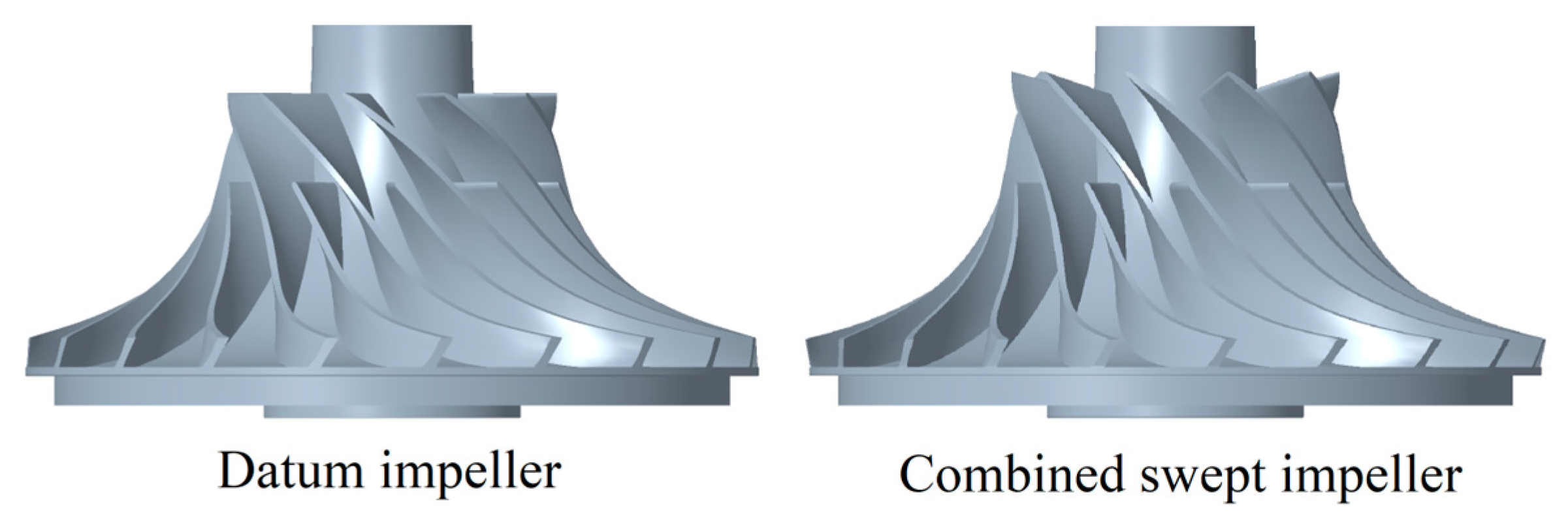
3.2. Combined Swept Impeller Model

Based on the above study results of the swept impellers at the leading or trailing edge, a combined swept impeller is investigated. Its leading edge is swept forward and the trailing edge is swept backward at the same time, the meridional shape of which is shown in Figure 7. Figure 8 shows the three-dimensional geometry of the unswept datum impeller and combined swept impeller.

4. Results and Analysis

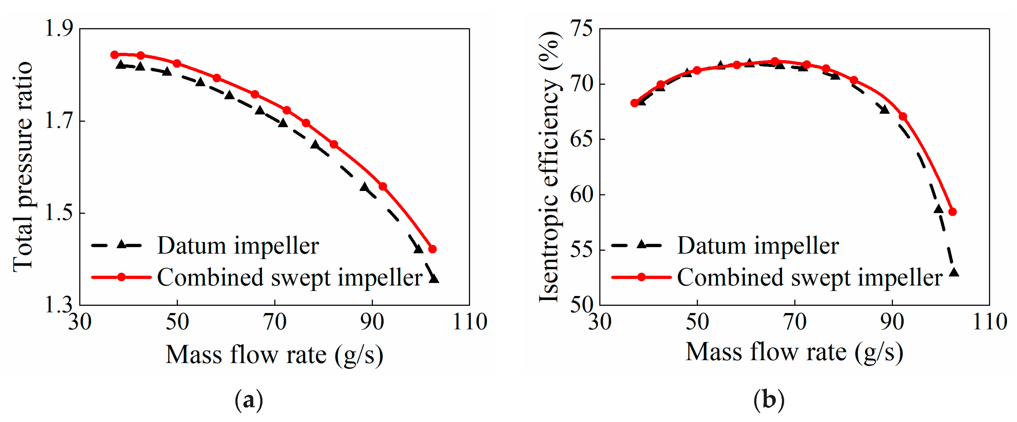
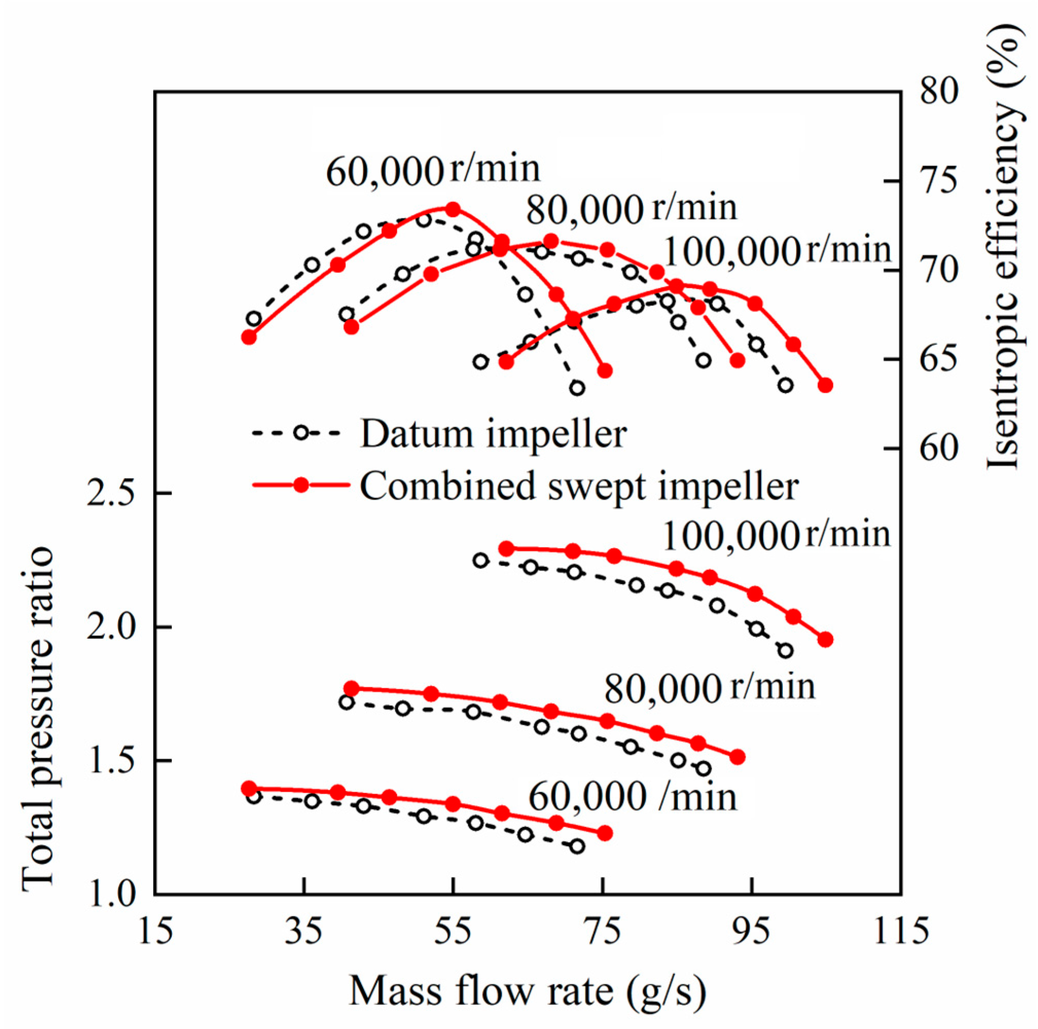
4.1. Overall Performance Comparison

The predicted total pressure ratio and efficiency of the combined swept impeller are compared with the performance of the datum impeller in Figure 9. A marked difference can be seen in the total pressure ratio, indicating that the highest pressure ratio of combined swept impellers is up to 1.3% higher than that of the datum impeller in Figure 9a. Figure 9b shows the efficiency of the compressor for the two type impellers. The efficiency is obviously improved by the combined swept impeller in the high mass flow range, i.e., there is an increase of 5.5 percentage points at blockage point. The efficiency improvement ability is weakened with the decrease of mass flow rate and no differences are seen in low mass flow range near surge point for these two impellers.

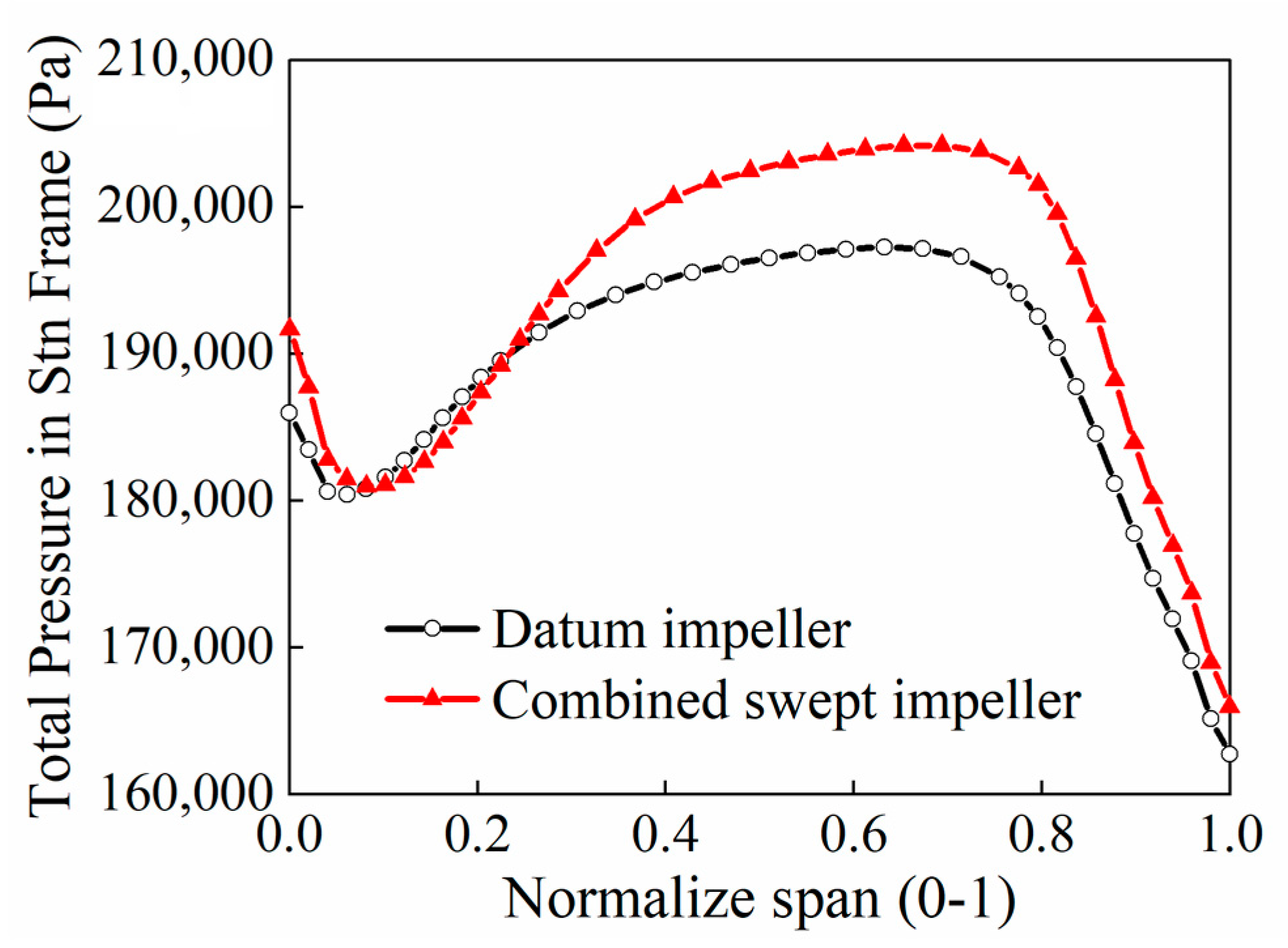
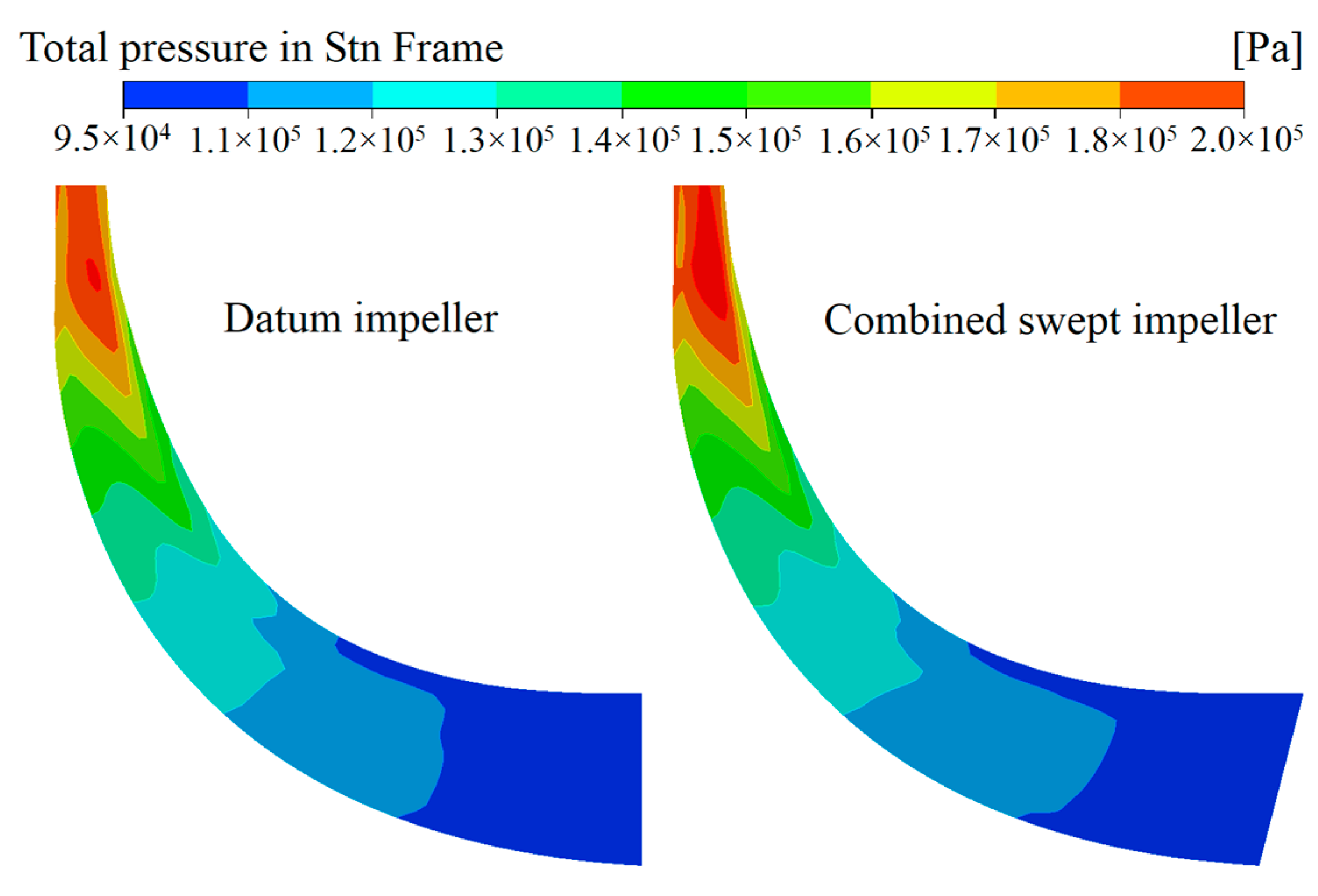
4.2. Detailed Analysis of Impeller Flow Field

In order to understand the mechanism of swept effects, further studies are made by investigating the flow in the choking condition and the highest efficiency condition.

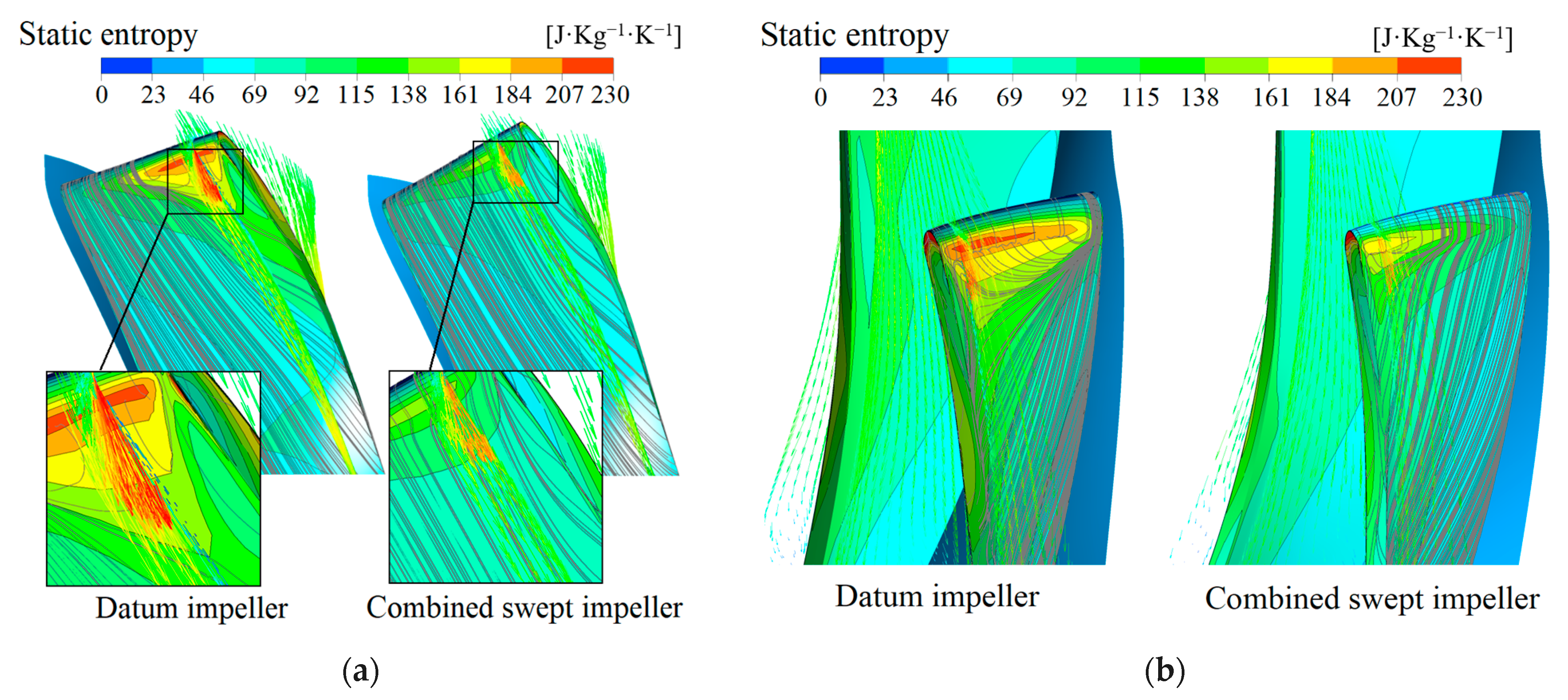
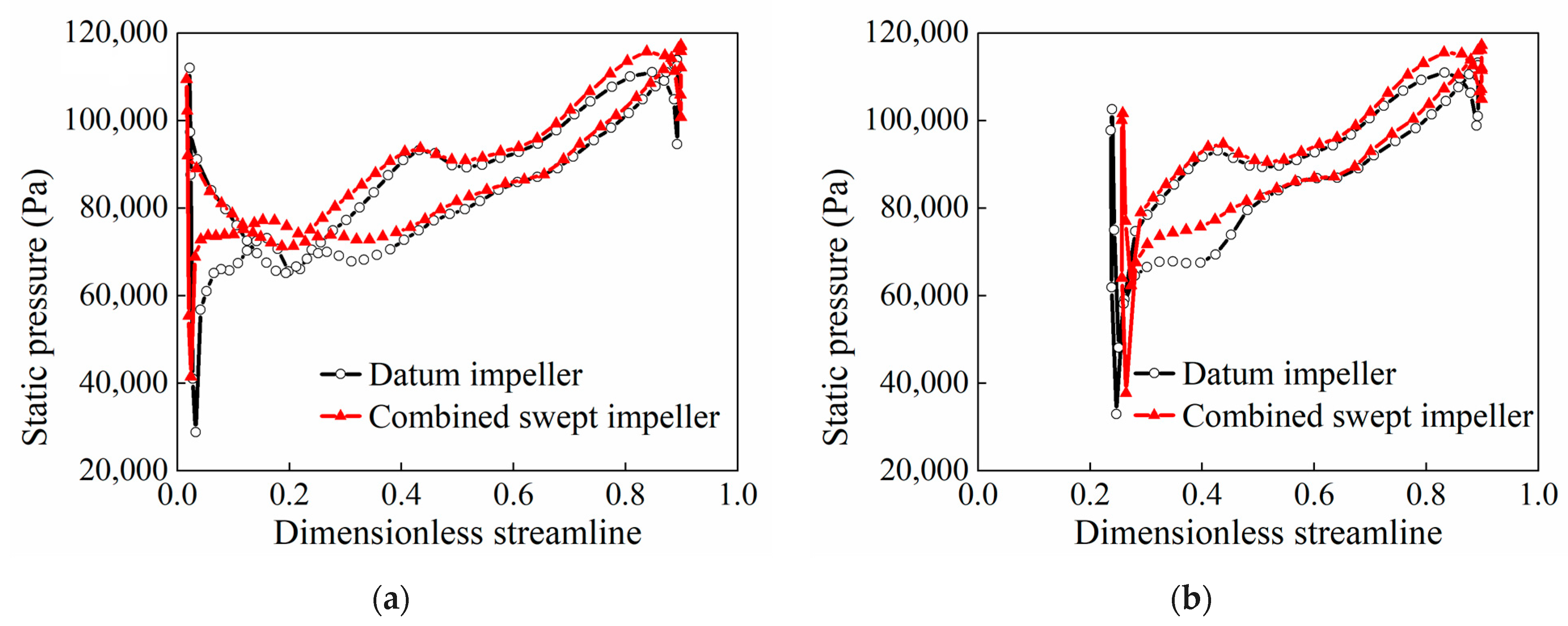
4.2.1. Choke Mass Flow Rate

The contours of Mach number at the tip section are shown in Figure 10 for the datum impeller and combined swept impeller near choke point. Both impellers show a small-scale supersonic zone, which is located at the leading edge of the main blade and splitter blade, forming a small-scale shock wave to hinder the gas flow. A large-scale low-energy flow is seen at the back part of passage, which is formed by the interaction of downstream tip leakage flow and secondary flow, and they migrate to blade tip under the action of centrifugal force and Coriolis force. The flow blocks the mainstream flow. Compared with the datum impeller, the supersonic zone of the main blade almost disappears, while the supersonic zone of the splitter blade is obviously weakened at the leading edge of the combined swept impeller. Additionally, the upstream flow of flow passage is more uniform.
Figure 11 shows the static entropy and streamline distributions on the blade surfaces of the datum impeller and combined swept impeller and the velocity vector distribution of 80% span. As is seen in the Figure 11, the high entropy region of the main blade is mainly located at the leading edge of the pressure surface, but it distributes at the leading edge of suction side for the splitter blade. Significant flow separation occurs in the high entropy region. For the main blade (i.e., Figure 11a), the flow rate is large in the choke condition, and forms a negative incidence angle at the leading edge. It impacts the suction surface and accelerates the flow on the pressure surface to generate a local reverse pressure gradient, which results in the airflow separation in the boundary layer and increases of friction loss and separation loss. For the splitter blade (i.e., Figure 11b,) due to the certain thickness of the splitter blade, the flow area decreases when gas flows through the splitter blade leading edge, and forms a local high speed and low-pressure region, resulting in flow separation. From Figure 11, it can also see that the high entropy region in the combined swept impeller is smaller than that of the datum impeller, which indicates loss decreases at the blade leading edge. The reason is that the airflow acceleration at the blade leading edge is reduced by using the combined sweep, and the reverse pressure gradient caused by airflow acceleration is also reduced. Thus, the separation of the boundary layer and the radial movement of the blade surface airflow have been suppressed.
Figure 12 shows blade load distribution at the 85% span of the datum impeller and combined swept impeller. It is seen that the blade load increases steadily spanwise, and static pressure of the blade pressure surface is higher than that of the suction surface. From Figure 12a, it can be seen that, for the main blade, due to the airflow acceleration at the leading edge, the pressure of the pressure side is lower than that of the suction side, and the pressure significantly fluctuates at the position corresponding to the leading edge of the splitter. Similar conclusions are shown in the splitter (i.e., Figure 12b), which is also affected by the airflow acceleration at the leading edge. With combined sweep, the blade pressure difference between pressure side and suction side of the main blade leading edge is decreased. The static pressure fluctuation of the main blade is weakened, which is conducive for the impeller to work on the gas to obtain the stable pressure rise. It is worth mentioning that the significant increase in the static pressure of the combined swept impeller near trailing edge indicates that its working capacity has been improved.
Static entropy distribution at 80% span and at different cross-sections of the downstream passage, as well as streamline distributions of the tip leakage (the red streamline represents the upstream leakage flow, and the black streamline represents leakage flow downstream), for two types of impellers are shown in Figure 13. A high-entropy region is seen in the downstream passage for the datum impeller and combined swept impeller, because the negative incidence angle of the main blade leading edge can cause tip leakage flow to reverse and flow across the tip clearance into the pressure side, and mix with the main flow in the adjacent passage. The leakage flow gradually strengthens as the flow direction and the leakage vortex are formed under the action of the casing and the lateral pressure gradient. The leading edge leakage vortex interacts with downstream tip leakage flow, forming an obvious high entropy region on the pressure side of the passage tip, corresponding to the low Mach number region in Figure 10. Specially, for the combined swept impeller, the high-entropy region in the flow channel is significantly reduced. This is because the static pressure difference at both sides of the main blade is small, and the reverse leakage flow and the leakage vortex are weakened. The interaction between the leakage vortex and the downstream leakage flow are also reduced, and then the flow loss decreased.
Figure 14 shows the total pressure distribution of datum and combined swept impellers at the outlet. The maximum total pressure of the datum impeller is mainly concentrated at the root of blade suction surface. For the combined swept impeller, it locates at the root of suction surface and the middle passage near the shroud. This is mainly because the work area of the blade increases by a backward sweep at the trailing edge. The lifting capacity of the impeller and the total pressure at the blade passage top is improved, which increases the total pressure at the outlet shroud.

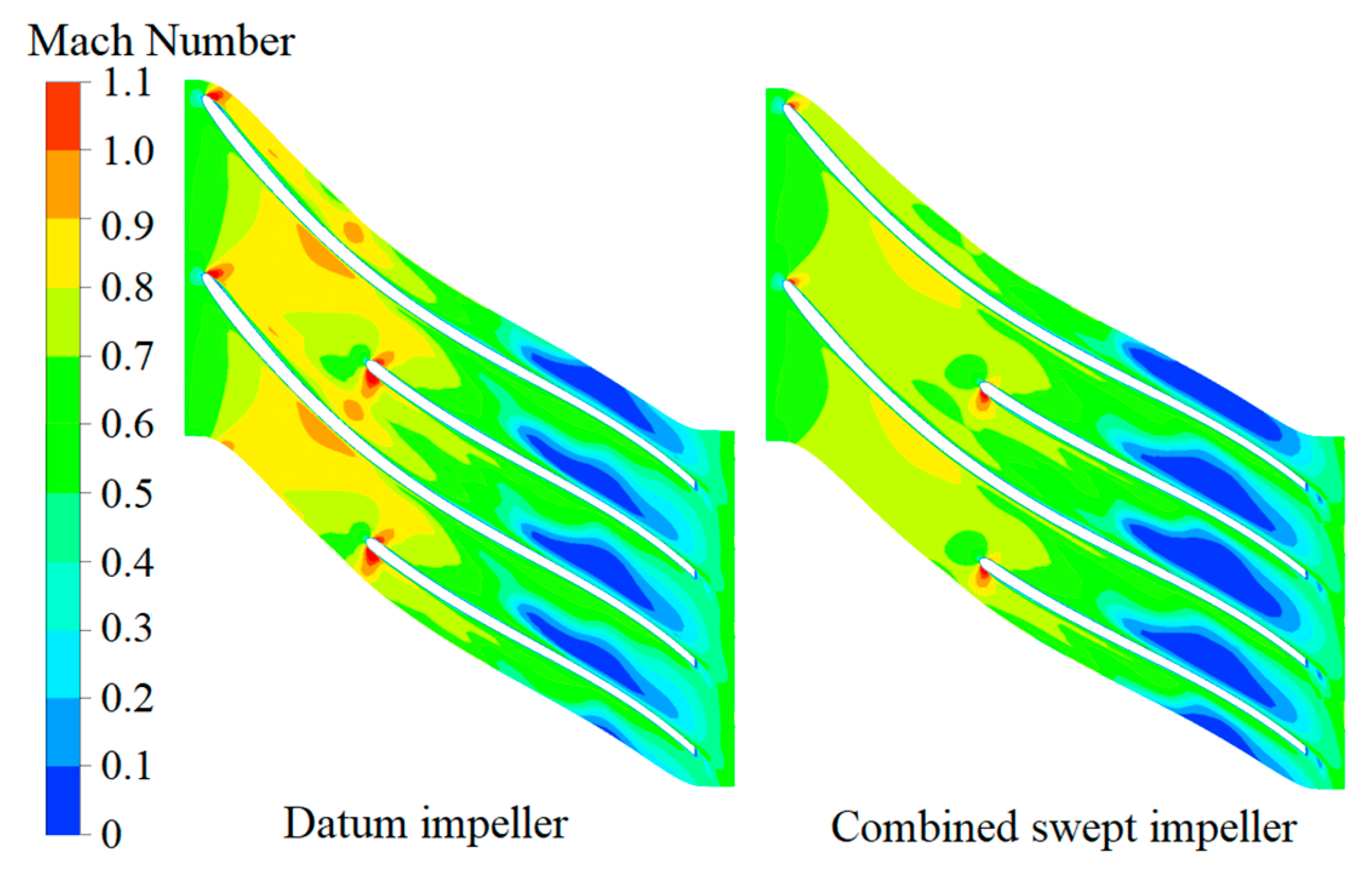
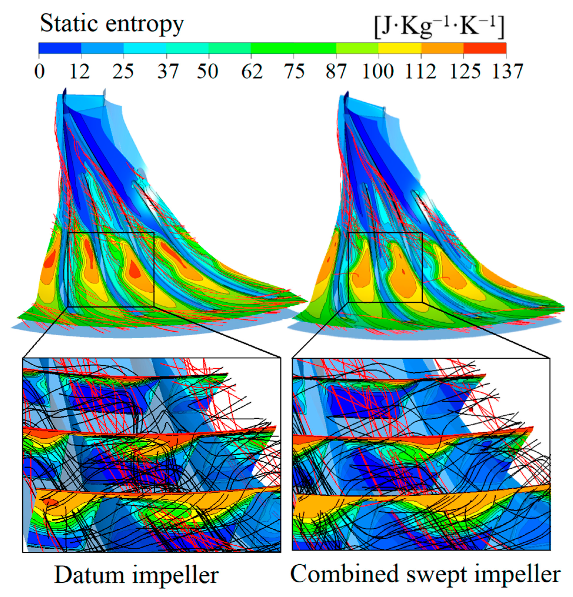
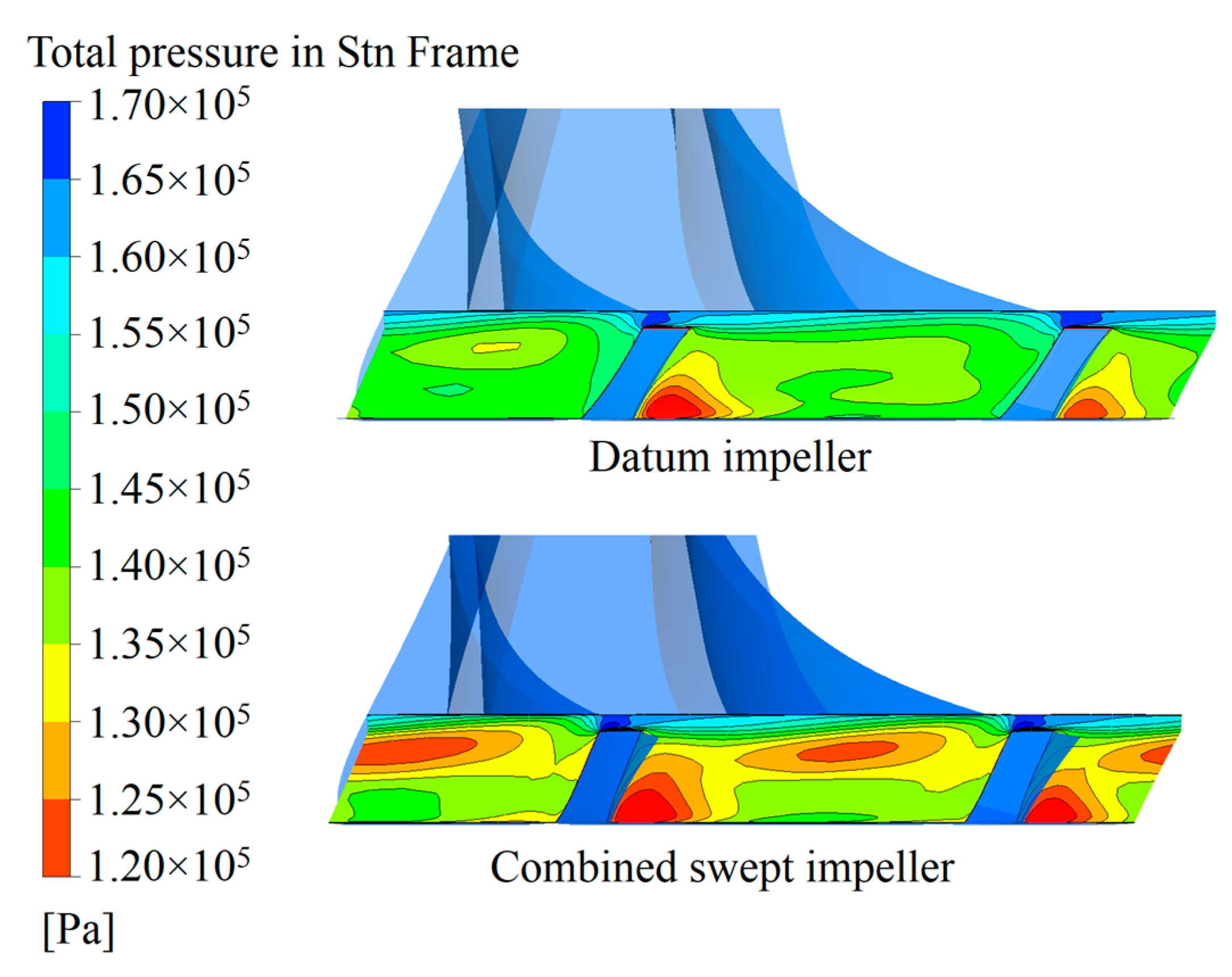
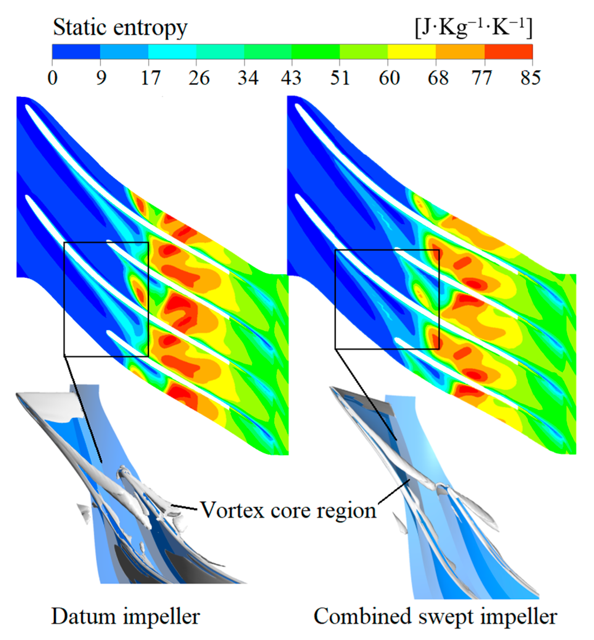
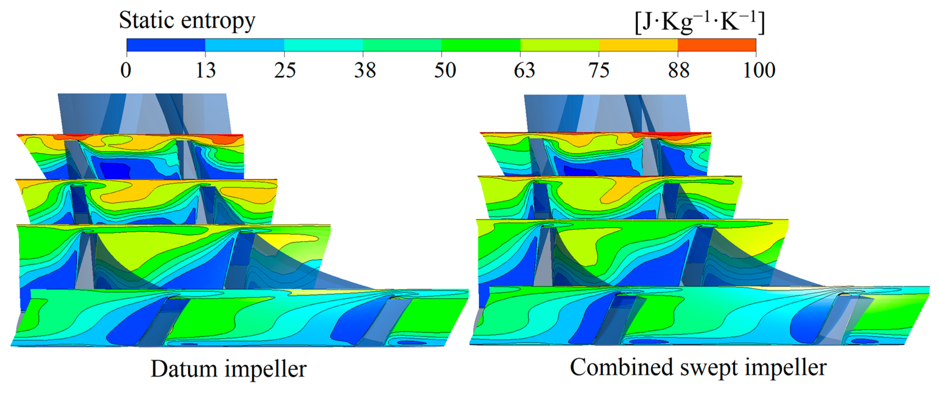
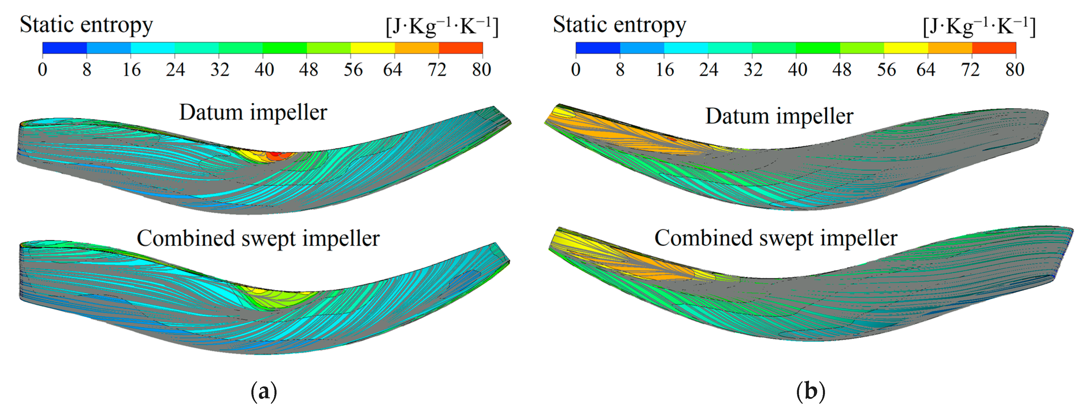
4.2.2. Highest Efficiency Mass Flow Rate

Figure 15 shows the static entropy distribution of the tip section and the leakage vortex core in the datum impeller and combined swept impeller. As shown in Figure 15, both impellers have obvious leakage vortices on the main blade suction side, and corresponding entropy value relatively increases in the static entropy distribution contour. In addition, a high-entropy region of the entire channel is seen in the middle span, where the location of the three-dimensional impeller axial-to-radial parts and the flow is complicated. For the combined swept impeller, leakage vortex is closer to leading edge and the strength is reduced. The tip chord length of the combined swept impeller is increased, the leading edge blade load is reduced, and the circumferential velocity is large.
Figure 16 shows several static entropy contours on different cross-sections at the middle and downstream passage. The entropy distributions in datum and combined swept impellers are compared. The high entropy region gradually moves from the middle of the passage tip to the suction side in the flow direction. For the interaction between the leading edge leakage vortex, the leakage flow at the bend passage, and friction with the casing, a large amount of low-energy fluid produces and accumulates on the passage tip. Under the action of centrifugal force and Coriolis force, it curls downward and moves to the suction side. As can be seen from Figure 16, the high entropy region in the passage of the combined swept impeller becomes smaller and the loss is reduced. This is because the strength of the leading edge leakage vortex is significantly weakened, and its mixing loss with the downstream leakage flow and the main flow is reduced. Thereby the generation of low-energy fluids is reduced.
Figure 17 shows static entropy and streamline distribution on the main blade surface of the datum impeller and combined swept impeller. From Figure 17a, it can be seen that the high entropy region of the pressure surface is mainly located at the tip of the middle blade, which is formed as the tip leakage flow impacts the blade pressure surface and interacts with the pressure surface secondary flow. The secondary flow at the tail of the blade surface is strengthened and eventually evolves into the tip leakage flow. Figure 17b shows that the high entropy region of the suction surface is mainly distributed near the blade tail because the tip leakage flow is involved in the upstream low-energy flow and mixed with it near the suction surface. At the trailing edge, there appears to be obvious flow separation, respectively forming distinct attachment line and separation line on the suction surface. In comparison with the datum impeller, the high entropy region on the surface of the combined swept blade and the low-energy flow region near the suction side formed by the tip leakage are both reduced, indicating that the trailing edge backward swept can inhibit the development of the wake region and reduce the generation of flow separation in the passage exit.
Figure 18 shows the distribution curve of total pressure along the span at the outlet of the datum impeller and combined swept impeller. As can be seen, the total pressure near the shroud is affected by the cross flow, so that the total pressure from the blade root to the tip increases first and then decreases as a whole. The total pressure difference of the tip region between the datum and the combined swept impeller is large because the combined swept impeller trailing edge is swept back, the pressure lifting capacity of the blade to the flow in the tip region is enhanced, and the total pressure at the impeller outlet is increased obviously.
Figure 19 shows the distribution of total pressure on the meridian surface of the datum impeller and combined swept impeller. It can be seen that the total pressure of the meridional surfaces of the two impellers has the same variation trend, in which the total pressure of the flow gradually increases from the inlet to the outlet. Since the work of the impellers on the fluid increases the kinetic energy and pressure energy, there is an obvious total pressure gradient at the shroud, and it is affected by the tip leakage. As the combined swept impeller increases blade work area and improves pressure lifting capacity of the impeller, the high pressure region is significantly enlarged. The total pressure distribution at the outlet is more uniform, reducing flow migration between the hub and the shroud.

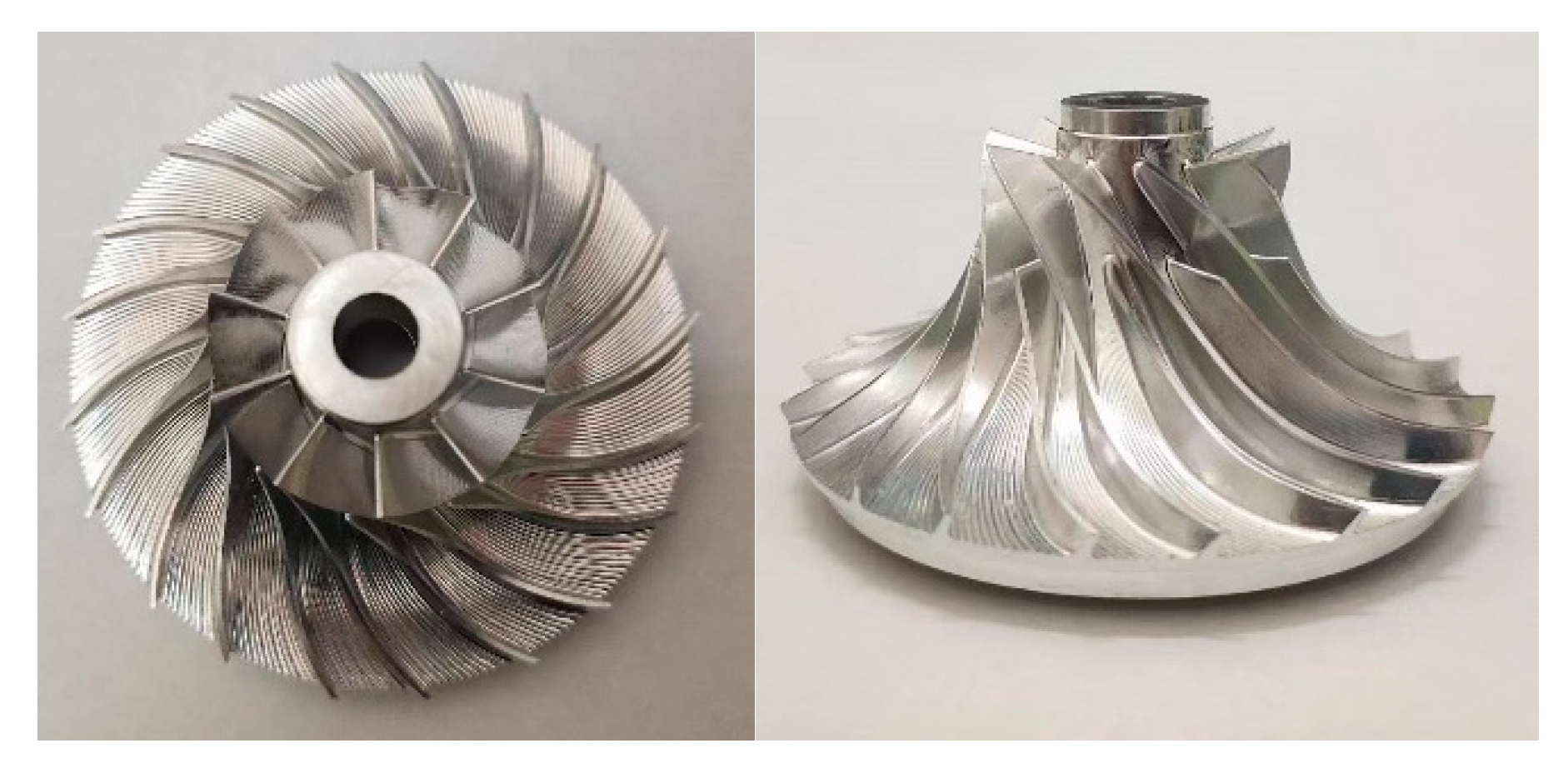
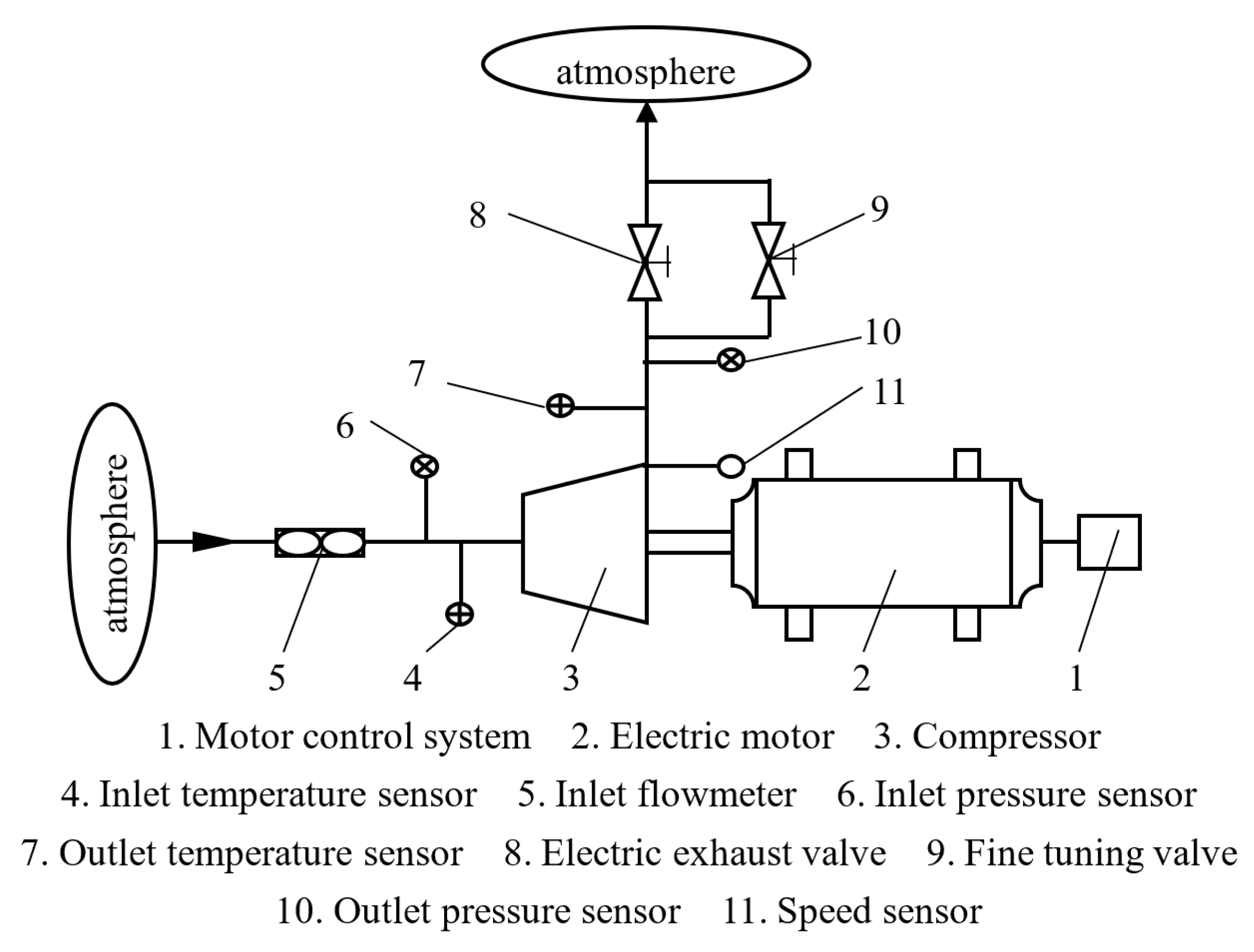
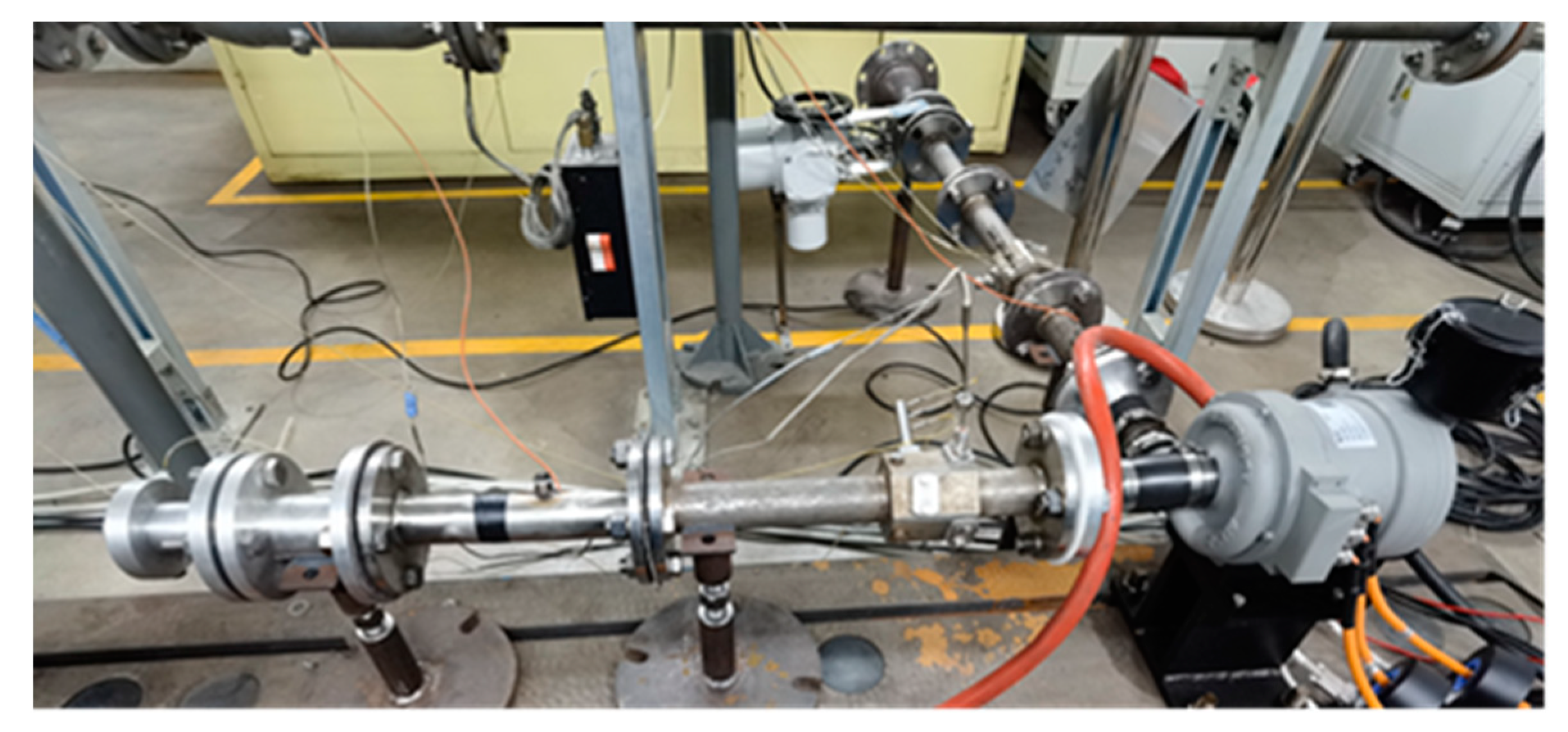
5. Manufacture and Test Rig

The combined swept impeller is structurally designed and processed, as shown in Figure 20.
The electric supercharger performance test bench was built from the experimental schematic in Figure 21, as shown in Figure 22. The centrifugal compressor was powered by a motor and the target speed of the test was controlled by the motor drive system. Three rotational speeds of 60,000, 80,000, and 100,000 r/min were tested in turn from low to high. At each rotational speed, the test was performed from blocking flow to surge flow. During the test, the compressor test conditions were adjusted by changing the outlet valve of the experimental system, and there were no less than five in each constant speed line. Except for the surge point, other operating points needed to be stable for three to five minutes before collecting parameters. After the test was completed, the speed was slowly reduced and the electric supercharger was turned off.
The information on the main instruments used in the experiment is shown in Table 3.
Figure 23 compares the experimental performance curves of low specific speed centrifugal compressors with datum and combined swept impellers. Under all operating conditions, the stage pressure ratio of the centrifugal compressor with combined swept impeller was improved, and the pressure ratio increased more obviously with rises in the speed, among which the maximum increase of pressure ratio at 100,000 r/min was 6.5%. For the efficiency curve, the maximum efficiency point of combined swept impeller shifted to the choke point, and the efficiency was improved at high flow rate and slightly decreased at small flow rate. In addition, the operating range of the compressor was extended as the blockage flow increases, by an average of 8% at the three speeds. This indicates that the combined sweep is an effective method to improve the performance of the low specific speed centrifugal compressor.

6. Conclusions

In this paper, numerical simulation was used to study the centrifugal compressor with low specific speed of leading/trailing edge combined swept impeller. The internal flow of the impeller under different operating conditions was analyzed in detail, and the reasons for the influences of the combined swept impeller on the compressor performance were revealed. Experiments have verified the effectiveness. The main conclusions are as follows:
In the operating conditions, the stage pressure ratio of the compressor can be increased by using a combined swept impeller. The compressor efficiency can be markedly improved at high flow rates, and the improvement ability decreases with the flow rate.
The combined swept impeller increases the working area of the blade and improves the working ability of the impeller. The total pressure at the impeller outlet is obviously increased.
The combined swept impeller reduces the flow incidence angle, improves the flow separation, and reduces the separation loss at the blade leading edge. Meanwhile, the blade leading edge load decreases due to the increase of the tip chord length, which effectively inhibits the strength of the leading edge leakage and weakens the formation and development of the tip leakage vortex.
In the future, the optimization algorithm and compressor performance prediction model can be further utilized to achieve an accurate and efficient low specific speed centrifugal compressor.

Author Contributions

Conceptualization, H.T. and D.T.; methodology, K.H.; investigation, S.L. and C.M. All authors have read and agreed to the published version of the manuscript.

Funding

This research was funded by the National Natural Science Foundation of China (Grant No. 12102123) and the National Science Foundation of Hebei Province (Grant No. A2021202014, A2022202008).

Data Availability Statement

Not applicable.

Acknowledgments

The authors would like to thank the National Natural Science Foundation of China and the National Science Foundation of Hebei Province for support the paper.

Conflicts of Interest

The authors declare no conflict of interest.

Nomenclature

n Design rotating speed/r·min−1
z Number of blades
t Tip clearance/mm
D1s Impeller inlet tip diameter/mm
D2 Impeller outlet diameter /mm
D3 Vaneless diffuser inlet diameter/mm
b3 Vaneless diffuser width/mm
D4 Volute inlet diameter /mm

References

  1. Wan, Y.; Guan, J.; Xu, S. Improved empirical parameters design method for centrifugal compressor in PEM fuel cell vehicle application. Int. J. Hydrogen Energy 2017, 42, 5590–5605. [Google Scholar] [CrossRef]
  2. Zheng, X.; Zhang, Y.; He, H.; Qiu, Z. Design of a centrifugal compressor with low specific speed for automotive fuel cell. In Proceedings of the ASME Turbo Expo 2008: Power for Land, Sea and Air, Berlin, Germany, 9 June 2008. [Google Scholar] [CrossRef]
  3. Liu, R.T.; Xu, Z. The research development of internal flow in centrifugal turbomachinery. Adv. Mech. 2003, 33, 518–532. [Google Scholar]
  4. Chen, H.; Zhuge, W.; Zhang, Y.; Ma, X.; Tao, L. Performance improvement of a centrifugal compressor for the fuel cell vehicle by tip leak-age vortex control. J. Therm. Sci. 2021, 30, 2099–2111. [Google Scholar] [CrossRef]
  5. Cravero, C.; Marsano, D. Criteria for the stability limit prediction of high speed centrifugal compressors with vaneless diffuser: Part I—Flow structure analysis. In Proceedings of the ASME Turbo Expo 2020: Turbomachinery Technical Conference and Exposition, Virtual, 21 September 2020. [Google Scholar] [CrossRef]
  6. Cravero, C.; Marsano, D. Criteria for the stability limit prediction of high speed centrifugal compressors with vaneless diffuser: Part II—The development of prediction criteria. In Proceedings of the ASME Turbo Expo 2020: Turbomachinery Technical Conference and Exposition, Virtual, 21 September 2020. [Google Scholar] [CrossRef]
  7. Ceyrowsky, T.; Hildebrandt, A.; Schwarze, R. Numerical investigation of the circumferential pressure distortion induced by a centrifugal compressor’s external volute. In Proceedings of the ASME Turbo Expo 2014: Power for Land, Sea and Air, Oslo, Norway, 11 June 2018. [Google Scholar] [CrossRef]
  8. Qiang, X.; Teng, J.; Du, Z. Influence of various volute designs on volute overall performance. J. Therm. Sci. 2010, 19, 505–513. [Google Scholar] [CrossRef]
  9. Xu, C.; Amano, R.S. Aerodynamic and structure considerations in centrifugal compressor design: Blade lean effects. In Proceedings of the ASME Turbo Expo 2012: Power for Land, Sea and Air, Copenhagen, Denmark, 11 June 2012. [Google Scholar] [CrossRef]
  10. He, X.; Zheng, X. Mechanisms of sweep on the performance of transonic centrifugal compressor impellers. Appl. Sci. 2017, 7, 1081. [Google Scholar] [CrossRef]
  11. Xu, Y.D.; Li, C.; Lü, Q.Y.; Zhang, X.M.; Mu, G.Z. The influence of the trailing edge angle of the micro centrifugal impeller on the performance of the centrifugal compressor. Int. J. Appl. Electrom. 2021, 66, 619–633. [Google Scholar] [CrossRef]
  12. Hah, C.; Puterbaugh, S.L.; Wadia, A.R. Control of shock structure and secondary flow field inside transonic compressor rotors through aerodynamic sweep. In Proceedings of the ASME Turbo Expo 1998: Power for Land, Sea and Air, Stockholm, Sweden, 23 December 1998. [Google Scholar] [CrossRef]
  13. Govardhan, M.; Kumar, O.; Sitaram, N. Computational study of the effect of sweep on the performance and flow field in an axial flow compressor rotor. Proc. Inst. Mech. Eng. Part A J. Power Energy 2007, 221, 315–329. [Google Scholar] [CrossRef]
  14. Cui, W.; Xiang, X.; Zhao, Q.; Xu, J. The effect of sweep on flowfields of a highly loaded transonic rotor. Aerosp. Sci. Technol. 2016, 58, 71–81. [Google Scholar] [CrossRef]
  15. Ganesh, C.S.; Nagpurwala, Q.H.; Dixit, C.S. Effect of leading edge sweep on the performance of a centrifugal compressor impeller. SAS. Tech-Tech. J. RUAS 2010, 9, 55–62. [Google Scholar]
  16. Guo, L.; Liu, Y.; Zheng, X.; Cui, Q. Effect of hybrid leading edge sweep on the aerodynamic performance of small scale transonic centrifugal compressor. Trans. CSICE 2016, 34, 281–287. [Google Scholar] [CrossRef]
  17. Zhao, H.; Lu, X.; Zhao, G.; Ma, R. Effects of compound sweep and lean on the aerodynamic performances of transonic centrifugal impellers. In Proceedings of the IOP Conference Series: Earth and Environmental Science, Dalian, China, 28 September 2019. [Google Scholar] [CrossRef]
  18. Li, Z.L.; Han, G.; Zhu, J.Q.; Lu, X.G. Flow mechanism of swept controlling internal flow of transonic centrifugal compressor. JASP 2022, 37, 826–835. [Google Scholar] [CrossRef]
  19. Hazby, H.; Robinson, C.; Casey, M.; Rusch, D.; Hunziker, R. Free-form versus ruled inducer design in a transonic centrifugal impeller. J. Turbomach. 2018, 140, 011010. [Google Scholar] [CrossRef]
  20. Wang, T.; Peng, C.; Wu, J. Back swept angle performance analysis of centrifugal compressor. Mechanika 2014, 20, 402–406. [Google Scholar] [CrossRef]
  21. Erdmenger, R.R.; Michelassi, V. Impact of main and splitter blade leading edge contour on the performance of high pressure ratio centrifugal compressors. In Proceedings of the ASME Turbo Expo 2014: Power for Land, Sea and Air, Stockholm, Sweden, 18 September 2014. [Google Scholar] [CrossRef]
  22. Hildebrandt, A.; Genrup, M. Numerical investigation of the effect of different back sweep angle and exducer width on the impeller outlet flow pattern of a centrifugal compressor with vaneless diffuser. J. Turbomach. 2007, 129, 421–433. [Google Scholar] [CrossRef]
  23. Li, W.J.; Du, L.M.; Guan, T.M. Influence mechanism of impeller trailing edge sweep on aerodynamic performance and internal flow field of a centrifugal compressor. J. Eng. Phys. Thermophys. 2022, 43, 3225–3234. [Google Scholar]
  24. Tian, H.Y.; Tong, T.; Liu, Y.; Xing, W.D.; Chen, D.F.; Gao, C. The effects of blade trailing edge swept on the performance of centrifugal compressor. J. Eng. Phys. Thermophys. 2021, 42, 399–406. [Google Scholar]
  25. Tian, H.Y.; Tong, T.; Zhang, J.Y.; Cheng, J.H.; Liu, X.Y. Flow characteristic of transonic centrifugal compressor with free-form sweep impeller at leading and trailing edges. Trans. CSICE 2021, 39, 554–560. [Google Scholar] [CrossRef]
  26. Methel, J.; Gooding, W.J.; Fabian, J.C.; Key, N.L.; Whitlock, M. The development of a low specific speed centrifugal compressor research facility. In Proceedings of the ASME Turbo Expo 2016: Turbomachinery Technical Conference and Exposition, Seoul, Republic of Korea, 13 June 2016. [Google Scholar] [CrossRef]
  27. Zhang, H.; Chen, Y.; Wang, Z. Investigations of the performance on vaned diffusers for low specific speed centrifugal compressor. Trans. Beijing Inst. Technol. 2021, 41, 258–265. [Google Scholar] [CrossRef]
  28. Kawanishi, T.; Tohbe, Y.; Kanazawa, N. Investigations of the performance on vaned diffusers for low specific speed centrifugal compressor. Int. J. Gas Turbine Propul. Power Syst. 2014, 6, 9–16. [Google Scholar] [CrossRef]
  29. Zhang, D.H.; Di, L.J.; Cave, M. A CFD study on a base and a flow-trimmed low specific speed centrifugal compressor. In Proceedings of the ASME 2010 International Mechanical Engineering Congress and Exposition, Vancouver, BC, Canada, 12–18 November 2010; Volume 5, pp. 89–94. [Google Scholar] [CrossRef]
  30. Wang, C.F.; Zhang, R.D.; Zhuge, W.L.; Zhang, Y.J.; Wei, J.J. Effect of leading edge swept on low specific speed centrifugal compressor performance. Automot. Saf. Energy 2017, 8, 432–436. [Google Scholar]
  31. Xu, C.; Chen, L.; Amano, R.S. Design and analysis of energy-efficient low-flow centrifugal compressors. J. Energy Resour. Technol. 2020, 142, 081307. [Google Scholar] [CrossRef]
  32. Li, X.; Huang, N.; Chen, G.; Zhang, Y.; Zhao, Y.; Zhang, J.; Tong, D. Numerical Simulation on the Influence of Inlet Flow Characteristics on the Performance of a Centrifugal Compressor. Energies 2023, 16, 3869. [Google Scholar] [CrossRef]
  33. Sundström, E.; Semlitsch, B.; Mihăescu, M. Similarities and Differences Concerning Flow Characteristics in Centrifugal Compressors of Different Size. In Proceedings of the 5th International Conference on Jets, Wakes and Separated Flows (ICJWSF2015), Stockholm, Sverige, 15 June 2015. [Google Scholar] [CrossRef]
  34. Celik, I.B.; Ghia, U.; Roache, P.J.; Freitas, C.J. Procedure for estimation and reporting of uncertainty due to discretization in CFD applications. ASME J. Fluids Eng. 2008, 130, 078001. [Google Scholar] [CrossRef]
  35. Trivedi, C.; Cervantes, M.J.; Gandhi, B.K. Investigation of a High Head Francis Turbine at Runaway Operating Conditions. Energies 2016, 9, 149. [Google Scholar] [CrossRef]
  36. Kan, K.; Xu, Z.; Chen, H.; Xu, H.; Zheng, Y.; Zhou, D.; Maxime, A.; Maxime, B. Energy loss mechanisms of transition from pump mode to turbine mode of an axial-flow pump under bidirectional conditions. Energy 2022, 257, 124630. [Google Scholar] [CrossRef]
Figure 1. Datum impeller of low specific speed centrifugal compressor.
Energies 16 04286 g001
Figure 2. Computational mesh: (a) impeller mesh; (b) stage mesh.
Energies 16 04286 g002
Figure 3. Comparison of CFD and experimental performance.
Energies 16 04286 g003
Figure 4. Sweep definition meridian view of centrifugal compressor.
Energies 16 04286 g004
Figure 5. Comparison of performance of different leading edge swept compressors.
Energies 16 04286 g005
Figure 6. Comparison of performance of different trailing edge swept compressors.
Energies 16 04286 g006
Figure 7. Meridional shape of combined swept impeller.
Energies 16 04286 g007
Figure 8. Three-dimensional geometric comparison of datum impeller and combined swept impeller.
Energies 16 04286 g008
Figure 9. CFD calculation results of non-swept and combined swept impeller performance: (a) pressure ratio characteristic curve; (b) isentropic efficiency characteristic curve.
Energies 16 04286 g009
Figure 10. Mach number distribution contours at 85% span.
Energies 16 04286 g010
Figure 11. Static entropy distribution contours on the blade surfaces of impeller: (a) main blade leading edge pressure surface; (b) splitter blade leading edge suction surface.
Energies 16 04286 g011
Figure 12. Static pressure distribution at 85% span: (a) main blade; (b) splitter.
Energies 16 04286 g012
Figure 13. Static entropy distribution contours of impeller blade tip sections and different cross-sections.
Energies 16 04286 g013
Figure 14. Total pressure distribution contours of impellers’ outlet section.
Energies 16 04286 g014
Figure 15. The static entropy distribution and the tip leakage vortex of the tip section.
Energies 16 04286 g015
Figure 16. Static entropy distribution contours of cross-sections.
Energies 16 04286 g016
Figure 17. Streamlines and static entropy distribution on the main blade surface: (a) pressure side; (b) suction side.
Energies 16 04286 g017
Figure 18. Total pressure distribution curve of the impeller outlet along the span (0 represents the hub, 1 represents the shroud).
Energies 16 04286 g018
Figure 19. Total pressure distribution contours on the meridian surface of the impeller.
Energies 16 04286 g019
Figure 20. The combined swept impeller.
Energies 16 04286 g020
Figure 21. Experimental schematic.
Energies 16 04286 g021
Figure 22. Electric supercharger performance test bench.
Energies 16 04286 g022
Figure 23. The experimental performance comparison of the datum impeller and combined swept impeller.
Energies 16 04286 g023
Table 1. Boundary conditions settings.
Boundary TypeSetting
InletTotal pressure 101,325 Pa, total temperature 298 K axial intake
Passage interfaceRotational periodicity
WallNo-slip, adiabatic
Rotor-stator interfaceMixing plane
OutletMass flow rate/Average static pressure
Table 2. Calculations of discretization error.
ParametersTotal Pressure RatioIsentropic Efficiency
r 21 1.3091.309
r 32 1.3171.317
Φ 1 1.749860.71768
Φ 2 1.739370.71424
Φ 3 1.646790.70490
p 8.0973.748
Φ ext 21 1.7510.71958
e a 21 /%0.5990.479
e ext 21 /%0.0720.265
G C I fine 21 /%0.0900.332
Table 3. Information about the instruments of the experiment.
InstrumentsRangeAccuracy
Flow Meter with Double Folium Curve0.01~0.27 kg/s±1.5%
2T-type thermocouple0~200 °C±0.5 °C
High precision pressure scanning valve−50~500 kpa±0.1%
Disclaimer/Publisher’s Note: The statements, opinions and data contained in all publications are solely those of the individual author(s) and contributor(s) and not of MDPI and/or the editor(s). MDPI and/or the editor(s) disclaim responsibility for any injury to people or property resulting from any ideas, methods, instructions or products referred to in the content.

