1. Introduction
Usually, coupled heat transfer involving various heat transfer forms occurs in a narrow cavity when there is a temperature difference between envelopes, of which the radiant heat transfer share could be significant. The thermal resistance of a vehicle/train envelope is one of the main factors determining thermal comfort and air conditioning energy consumption, and its improvement has always been of interest. Narrow cavities are commonly found in vehicle envelopes, sometimes to a large proportion, such as in the CEH3 high-speed train made in China, which has 50.2% [
1]. It could be a promising method to strengthen the thermal resistance of vehicle envelopes by decreasing the radiant heat transfer share in cavities scattered in envelopes. The practicable method and its effectiveness are worth studying.
Most studies analyze the radiation characteristics of the heat transfer of narrow cavities, especially by a numerical method. Rincón-Casado et al. [
2] provided a Rayleigh number (
Ra) function containing the aspect ratio of the enclosed cavity. Hinojosa et al. [
3] numerically determined the Reynolds number (
Re) and inclination angle effect on natural convection in an open cavity. Didier et al. [
4] experimentally analyzed the radiation effect on the Nusselt number (
Nu), temperature and velocity in the cavity. El-Sherbiny et al. [
5] and Kim et al. [
6] numerically verified that the wall surface emissivity of a cavity affects its heat transfer dramatically. Based on different numerical methods, references [
7,
8,
9,
10,
11] indicate that the average
Nu increases with increasing surface emissivity in a cavity. References [
12,
13,
14,
15] investigated the relationship between the radiation effect and the heat transfer in the cavity based on different numerical models. References [
16,
17,
18] numerically found that the radiant parameters significantly affect the characteristics of conjugate heat transfer in a closed cavity. It is clear that these studies focused on analyzing the thermal characteristics of various narrow cavities only. Although we can now conclude that the radiation effect could be significant in some narrow-cavity heat transfer processes, how to decrease the radiation share in cavity heat transfer by an effective and feasible method is uninvestigated, especially by experimental methods.
Based on the attempt to improve the insulation characteristics of the vehicle/train envelope, this paper will introduce a feasible method by pasting aluminum foil in the inner walls of the narrow cavity and combine experimental and numerical methods to indicate its enhanced effect on thermal resistance.
2. Experimental Studies
The narrow cavity is closed, with a thickness-to-height ratio of less than 0.06, and the four walls are adiabatic except for both large parallel walls; thus, the heat transfer could be regarded as a one-dimensional problem.
To obtain the aluminum foil effect on enhancing the thermal resistance of the narrow cavity: Firstly, the aluminum foil effect on the heat transfer of both horizontal cavities and vertical cavities will be studied by an experimental method (including 5 mm, 10 mm and 15 mm thickness); secondly, a numerical model and method for the narrow cavities will be built and verified by the test data; then, the aluminum foil effect on the heat transfer of the inclined cavities (30°, 45° and 60°) (including 5 mm, 10 mm and 15 mm thickness) will be studied by a numerical method. In the paper, CWOA refers to the narrow cavities without aluminum foil on the inner wall, CWSA refers to the narrow cavities with aluminum foil on one inner wall and CWDA refers to the narrow cavities with aluminum foil on both inner walls.
Based on the system in [
19], this paper first carried out the test on the heat transfer characteristics of various narrow cavities, including horizontal cavities and vertical cavities with various radiation characteristics.
2.1. Experimental Platform
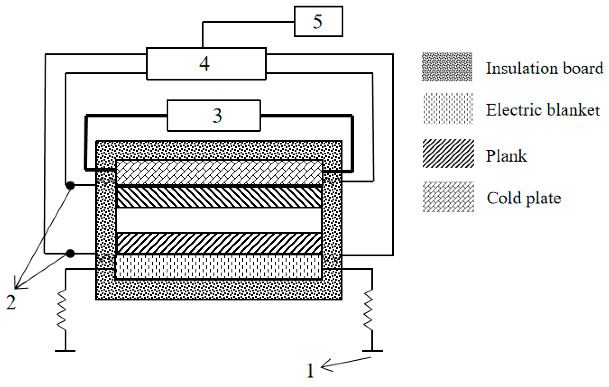
The experimental system is based on the principle of constant heat flow, which includes the test cavity and the auxiliary systems, such as an adjustable DC power, electric heating pad, both temperature test pads for the hot cold surfaces, cooling plate, constant temperature water bath and data acquisition system.
Figure 1 shows the test facility and cavity specimen placed horizontally. The horizontal cavity, whose hot surface is on the bottom, is only considered because pure heat conduction will occur when the hot surface is on the top.
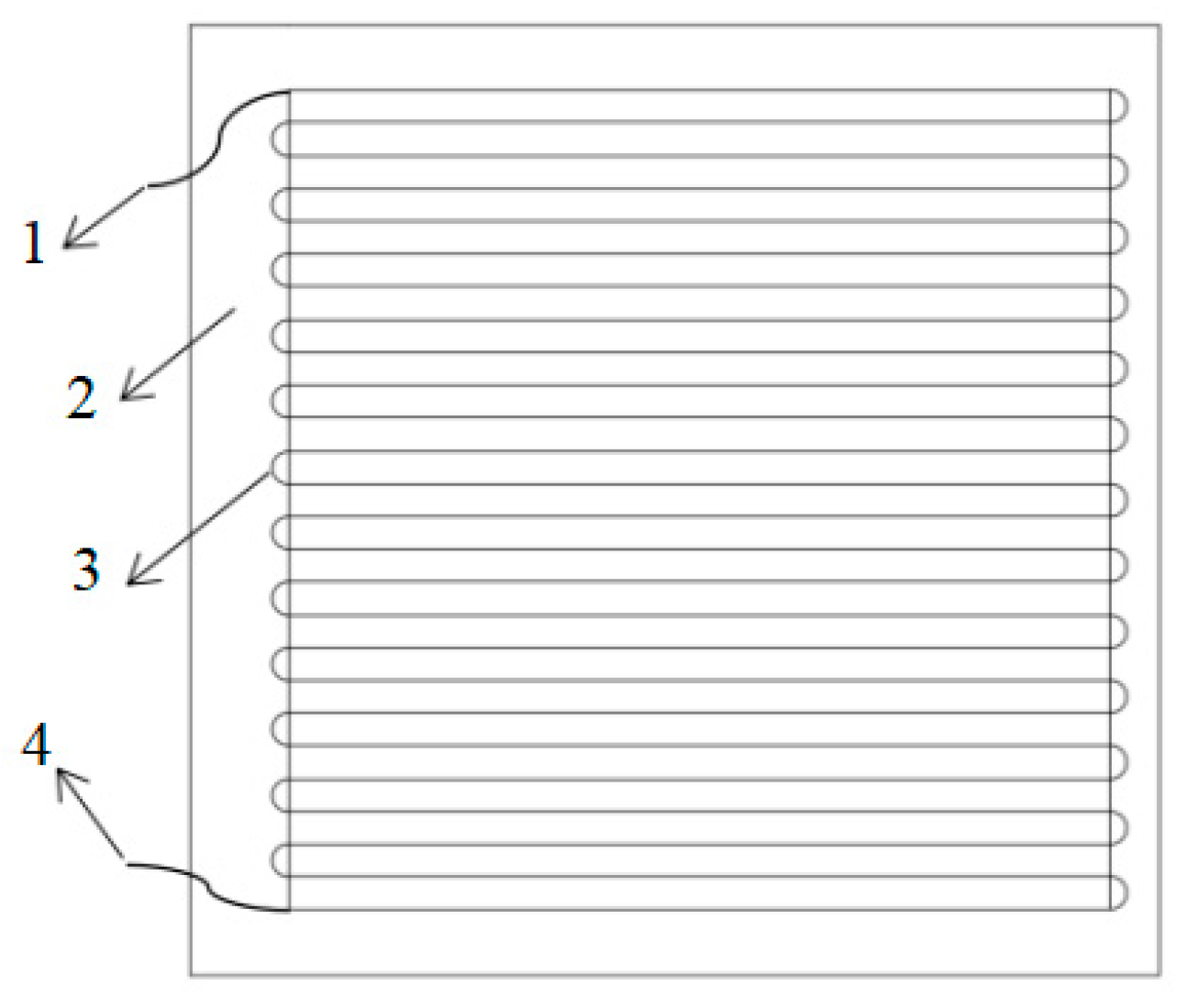
A Keithley 2700 multichannel data acquisition system with true six-and-a-half-bit (22-bit) accuracy from Keithley is used, and the wall temperature test pad shown in
Figure 2 is composed of a serpentine copper wire and a based cloth, which is based on the relationship between the wire resistance
I and its temperature
T as shown in Equation (1) [
20], where
I0 is the wire resistance at 273 K and ξ is the wire temperature coefficient of resistance, which is 0.004286.
In this paper, the cavity equivalent heat transfer coefficient
K and the radiation heat transfer share
r are used, which are defined as Equations (2) and (3).
where
q is the heat flux density, including heat conduction, convection and radiation per unit wall area (
qh,
qc,
qr), W/m
2; ∆
T is the temperature difference between both parallel large walls, K; and
qr can be defined as Equation (4).
where
σ is the radiation constant, 5.67 × 10
−8 W/(m
2·K
4);
Thm and
Tlm are the temperatures of the cold and hot surfaces, respectively, K; and
εs is the system emissivity of the narrow cavity shown as Equation (5), of which
ε1 and
ε2 are both parallel surface inner emissivities.
The relative error could originate from the heat loss of the cavity adiabatic surface (δ
q/
q) and the measured errors to cavity thickness (δ
δw/
δw) and the surface temperatures, which can be evaluated according to Equation (6) [
21], of which δ
q/
q is the maximum 3.85%.
Table 1 gives the error results, of which the maximum is not larger than 4.07%.
where
δw is the thickness of the cavity, m.
2.2. Test Specimens
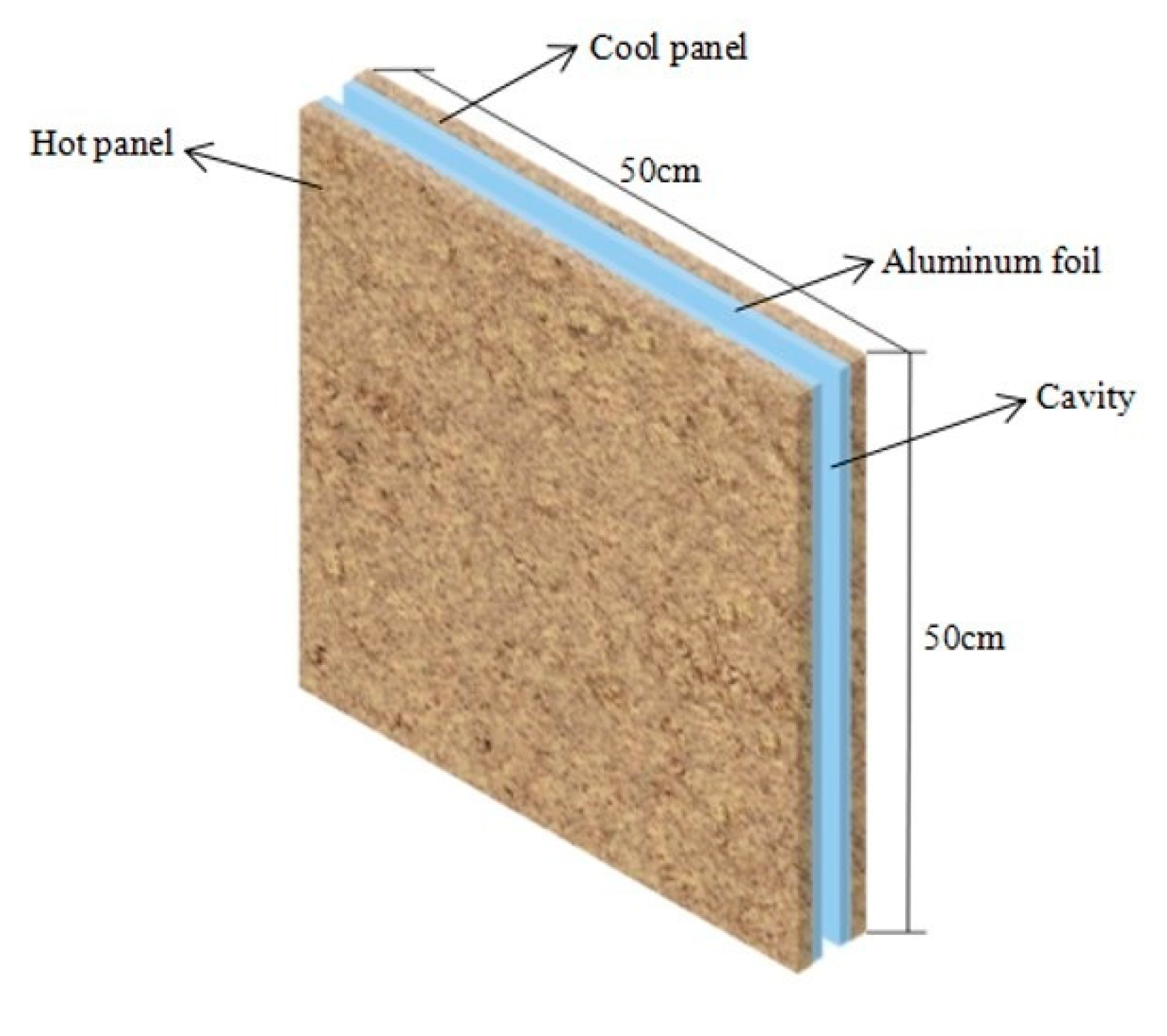
The narrow cavities tested in this paper include vertical cavities with thicknesses of 5 mm, 10 mm and 15 mm and horizontal cavities with thicknesses of 10 mm, 15 mm and 20 mm. The cavities are made of 5 mm thick wood, and their radiation characteristics are changed by configuring the inner walls without aluminum foil, with single-sided aluminum foil, and with double-sided aluminum foil.
Figure 3 shows the cavity geometry with double-sided aluminum foil.
Table 2 shows the information of the cavity and its materials.
2.3. Experimental Methods
- (1)
First, the water temperature is adjusted to 297 K from the constant temperature water bath, and the heat flux density is set to 25.2 W/m2 by adjusting the DC power.
- (2)
Second, when the temperature change rates of the two cavity walls are less than 0.2 K/h, the thermal equilibrium is obtained, and the test data are recorded.
- (3)
Third, according to the wall temperature and the heat flux density obtained, the equivalent heat transfer coefficient K and its radiation share r of the tested cavity specimen is calculated.
- (4)
According to the above method, the equivalent heat transfer coefficient K of the tested cavity corresponding to the respective heat flux densities of 25.2 W/m2, 41.4 W/m2, 59.4 W/m2, 74 W/m2 and 91.84 W/m2 can be obtained.
- (5)
Then, in accordance with the principle described above, the tests are repeated by replacing different test specimens in turn.
During the test, the equilibrium state is determined when the temperature change rates of the two cavity walls are all less than 0.2 K/h. The cavity without aluminum foil (CWOA) takes approximately 400 min to attain an equilibrium state, the cavity with single-sided aluminum foil (CWSA) takes approximately 450 min and the cavity with double-sided aluminum foil (CWDA) takes approximately 550 min.
2.4. Experimental Results and Analysis
The ambient relative humidity is basically constant at 45%RH during the experiments, and the humidity effect on the heat transfer in the cavity is not considered. By testing, the thermal conductivities of specimens 1 and 2 are 0.173 W/(m·K) and 0.168 W/(m·K), respectively. After pasting the aluminum foil, the cavity system emissivity is changed from 0.941 (CWOA) to 0.039 (CWSA) and 0.02 (CWDA), respectively.
2.4.1. Vertical Cavity (90°)
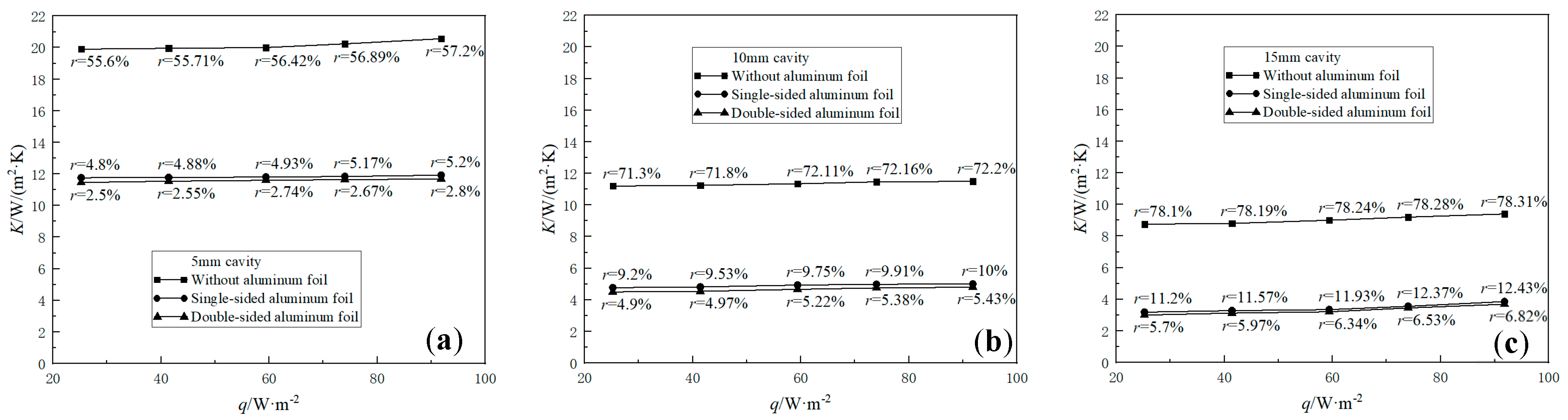
Figure 4 shows the radiation share
r in the vertical cavities with 5 mm, 10 mm and 15 mm thicknesses and their respective equivalent heat transfer coefficient
K with the wall heat flux
q.
It is known that the heat convection and radiation in the cavity will be enhanced as the wall temperature increases, and the radiation capacity is proportional to the fourth power of the wall temperature. When the heat flux density is increased from 25.2 W/m2 to 91.84 W/m2 in the same cavity, K and r both increase due to the higher wall temperature. The maximum increment ΔK is 0.69 W/(m2·K) in CWDA with 15 mm thickness, whose thermal resistance is maximum. It is assumed that the maximum increment Δr would also be in the cavity with the maximum resistance, but the maximum increment Δr is 1.6% in CWOA with 5 mm thickness, whose thermal resistance is minimum. The reason could be that convection was severely restricted in such a narrow cavity of 5 mm thickness.
Before the aluminum foil is pasted, r is dominant, with a maximum of 78.31% in CWOA with 15 mm thickness at 91.84 W/m2, and a minimum of 55.6% in CWOA with 5 mm thickness at 25.2 W/m2. After the aluminum foil is pasted, the sharp decrease of K and r indicates that the heat radiation effect on the heat transfer in the usual narrow cavities is dominant, and that it can be effectively suppressed by pasting the surface with low emissivity materials. Compared with CWOA of the same thickness at the tested heat flux density range, the average values of and in CWSA with 5 mm, 10 mm and 15 mm thickness are reduced by approximately 41%/91%, 57%/87% and 62%/85%, respectively. The aluminum foil effect in CWDA is slightly larger than in CWSA; the average values of and in CWDA with 5 mm, 10 mm and 15 mm thickness are enlarged by approximately 2%/47%, 5%/47% and 4%/47%, respectively.
When the cavity thickness increases, K decreases and r increases dramatically due to the thermal resistance, and the wall temperature increases. The average values of both and are 20.13/56.36,11.35/71.91 and 9.03/78.22 in CWOA with 5 mm, 10 mm and 15 mm thickness, respectively; 11.82/5, 4.9/9.68 and 3.44/11.9 in CWSA; and that are 11.58/2.65, 4.65/5.18 and 3.29/6.27 in CWDA. The difference between CWSA and CWDA is less.
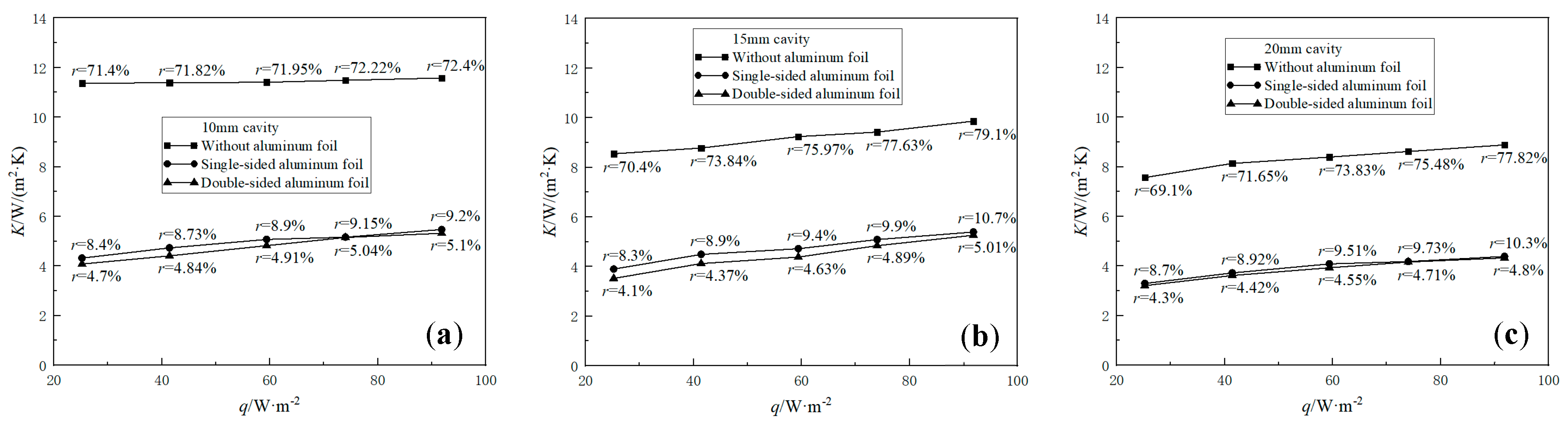
2.4.2. Horizontal Cavity (0°)
Figure 5 shows
r in the horizontal cavities with 10 mm, 15 mm and 20 mm thicknesses and their corresponding equivalent heat transfer coefficient
K with
q. The change trends and their reasons in the horizontal cavities are similar to that of vertical cavities, but the test data in both cavities are different. The average values
(W/(m
2·K)) and
(%) are 11.45/71.95, 9.17/75.39 and 8.32/73.57 in CWOA with 10 mm, 15 mm and 20 mm thickness, respectively; 4.95/8.88, 4.72/9.44 and 3.93/9.43 in CWSA and 4.76/7.92, 4.42/4.6 and 3.85/4.56 in CWDA.
The maximum increment ΔK is 1.74 W/(m2·K) in CWDA with 15 mm thickness, which is larger than that in CWDA with 20 mm thickness. The maximum increment Δr is 8.7% in CWOA with 20 mm thickness, because radiation is greatly improved due to the increased wall temperature.
Before the aluminum foil is pasted, r is also dominant, with a maximum of 79.1% in CWOA with 15 mm thickness at 91.84 W/m2, and a minimum of 69.1% in the CWOA with 20 mm thickness at 25.2 W/m2 due to improved convection. After the aluminum foil is pasted, the sharp decrease of K and r also occurred. Compared with CWOA of the same thickness at the tested heat flux density range, the average value and values in CWSA with 10 mm, 15 mm and 20 mm thickness are reduced by approximately 57%/88%, 49%/88% and 53%/87%, respectively. The aluminum foil effect in CWDA is also slightly larger than in CWSA, with the average values of and in CWDA with 10 mm, 15 mm and 20 mm thickness enlarged by approximately 4%/11%, 6%/51% and 2%/52%, respectively.
3. Numerical Analysis
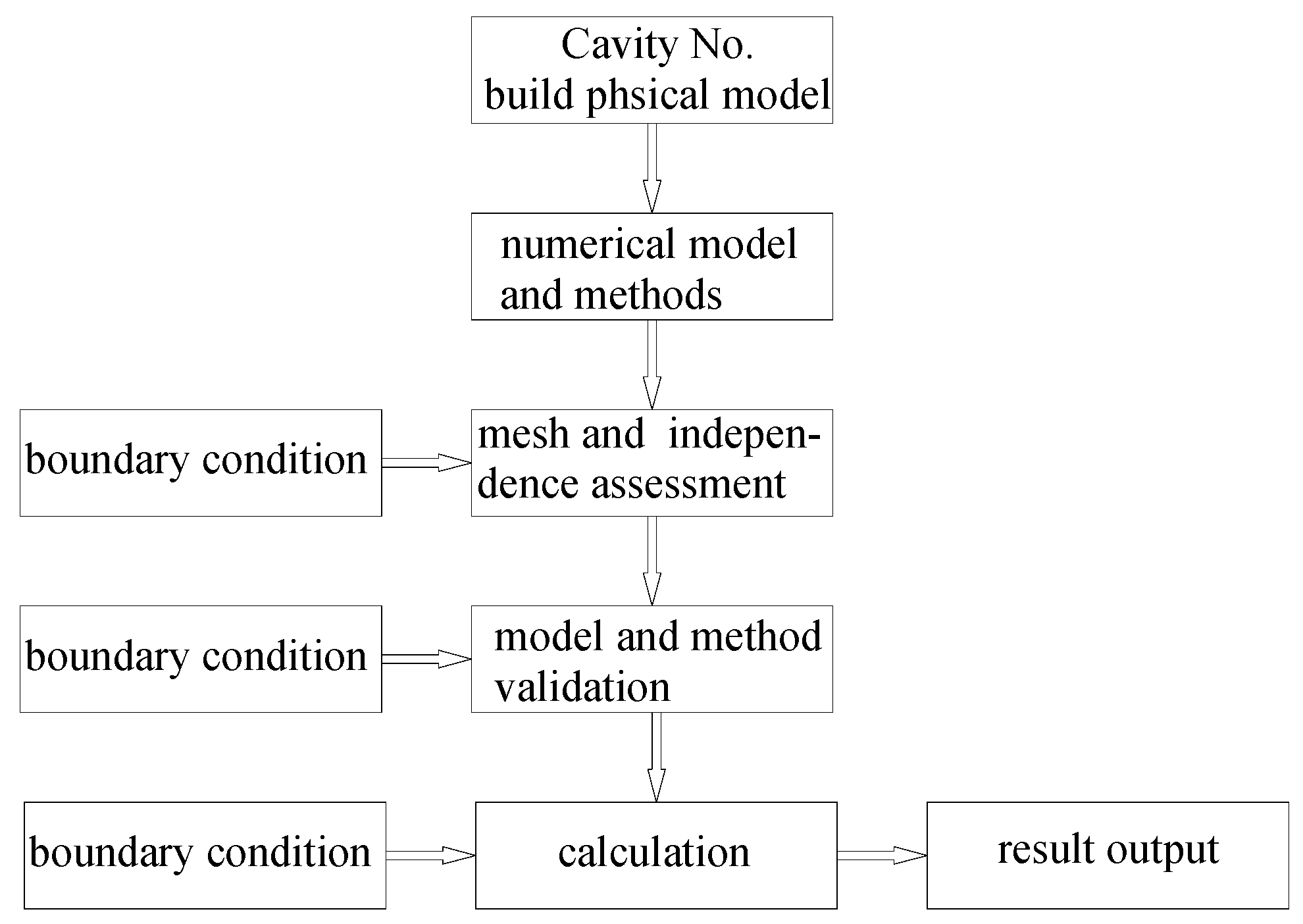
In practice, the inclined cavities with various angles could be more common in a vehicle/train envelope. To comprehensively reveal the aluminum foil effect on the heat transfer of the narrow cavity at various angles, the analysis of the heat transfer characteristics in the cavity with different thicknesses, inclination angles and system emissivity were carried out based on the previous experimental research results and the FLUENT software. Based on the finite volume method, FLUENT software has many mature models and advanced numerical methods, and its unstructured and adaptive mesh technique is also very effective, so the heat transfer problem can be quickly and accurately calculated.
Figure 6 is the flow chart of the numerical calculation.
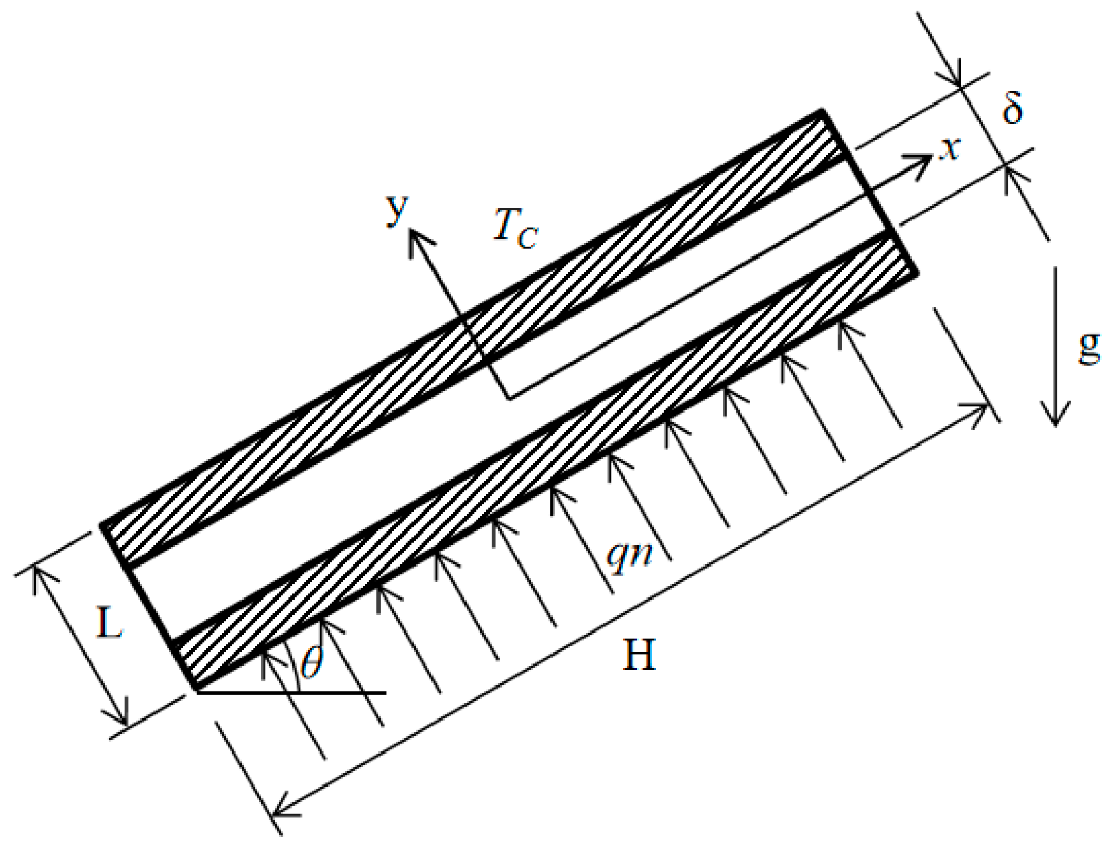
3.1. Physical Model
The two-dimensional physical model of a narrow closed cavity with a cross-sectional size of 500 × 500 mm and a thickness-to-height ratio of less than 0.06 is shown in
Figure 7, where both large parallel surfaces are of equal heat flux and the upper surface is cooled while the other surfaces are adiabatic, and the constituent materials and parameters are the same as those in the experiment.
3.2. Numerical Model and Method
The heat transfer in the narrow cavity involves conduction, convection and radiation. In this paper, the problem is considered as a two-dimensional steady-state laminar flow model that ignores the viscous dissipation effect, and the radiation effect is considered by the DO model embedded in the FLUENT software. The control volume method is used to discretize the control equation, in which the convective diffusion term is in a second-order windward format. The SIMPLE algorithm [
22] is used to solve the coupled velocity and pressure equations, in which the buoyancy effect is considered, and the body force is chosen for the pressure difference. As the convergence criterion to stop the calculation, a relative difference of 5% between the heat imported from the hot surface and the heat output by the cold surface is chosen. Except for the buoyancy force, the air parameters are set as constants, including 0.701 for the Prandtl number (
Pr), 300 K for the initial temperature, 101.325 kPa for the reference pressure, 0.9 for the inner wall emissivity of the cavity without aluminum foil and 0.04 for the inner wall emissivity of the cavity with aluminum foil. Except for the formulas mentioned above, the control equations also include the following equations [
23]. These equations are all suitable for the cavities mentioned in this paper, and the difference between these problems is dependent on their physical models.
Continuity equation shown as Equation (7):
Momentum equation shown as Equations (8) and (9):
Energy equation shown as Equation (10):
The two-dimensional differential equation for thermal conductivity in the solid region of the two wood walls of the cavity is Equation (11):
where
u,
v,
p′, and
T are the velocity components, effective pressure and temperature, respectively;
ρ,
g,
β,
v, and
a are the density, gravitational acceleration, coefficient of thermal expansion, coefficient of viscous diffusion, and coefficient of thermal diffusion, respectively; and
λ is the thermal conductivity of the solid.
Equations (12) and (13) give the cavity wall boundary conditions at
x = H/2 and
x = −H/2, respectively.
Equations (14) and (15) give the cold and hot wall boundary conditions of the cavity at
y = −L/2 and
y = L/2, respectively.
Equations (16) and (17) give the cavity flow-solid coupling surface conditions at
y = −
δ/2 and
y =
δ/2, respectively, of which the equivalent conductivity
λair at the air side includes surface air conduction and radiation effects and
λaf refers to the conductivity of the aluminum foil.
3.3. Meshing and Its Independence Verification
To reduce the element number impact on the calculation results, several sets of nonuniform grids are used to discretize the calculation area based on the 15 mm thick CWOA at a 30° inclined angle to assess the element independence, where the element is encrypted near the walls with larger velocity and temperature gradients. The result based on the final three grids is given in
Table 3. Because the maximum relative error between both mesh systems is less than 5%, the minimum grid system of 100 × 25 was finally chosen to carry out the following numerical calculations based on the consideration of saving computer resources.
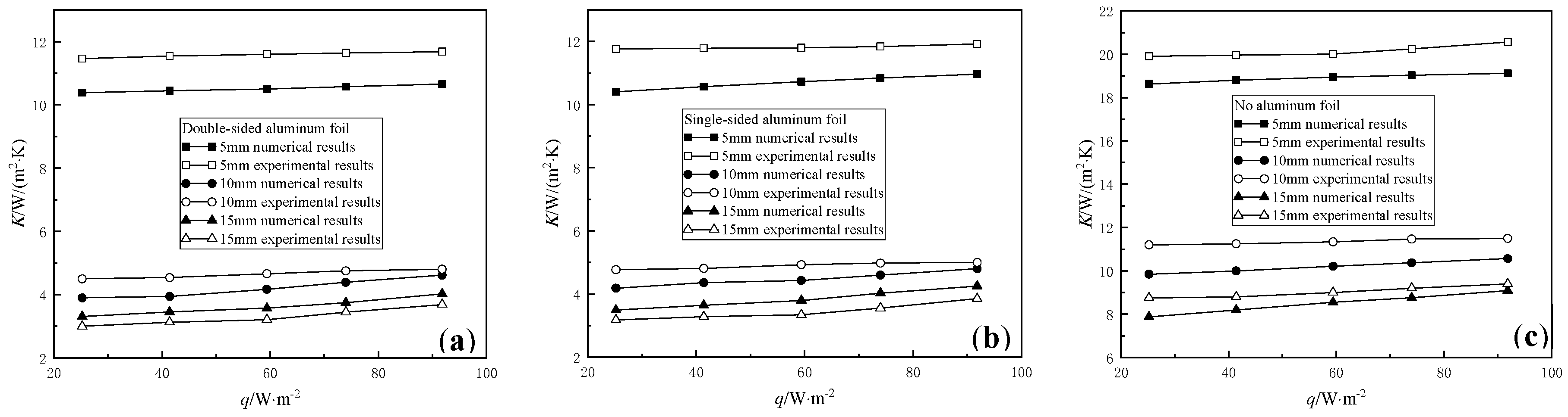
3.4. Validation of the Numerical Method
Values of
K of vertical cavities with different thicknesses based on the experimental data were selected to verify the numerical model and method in this paper, and the results are shown in
Figure 8.
It can be seen that the numerical results are in good agreement with the experimental data. The error between 2.5~13.63% could be from the difference of the physical parameters between the test and numerical calculations.
3.5. Results and Analysis
3.5.1. The Inclined Narrow Cavity at 30°
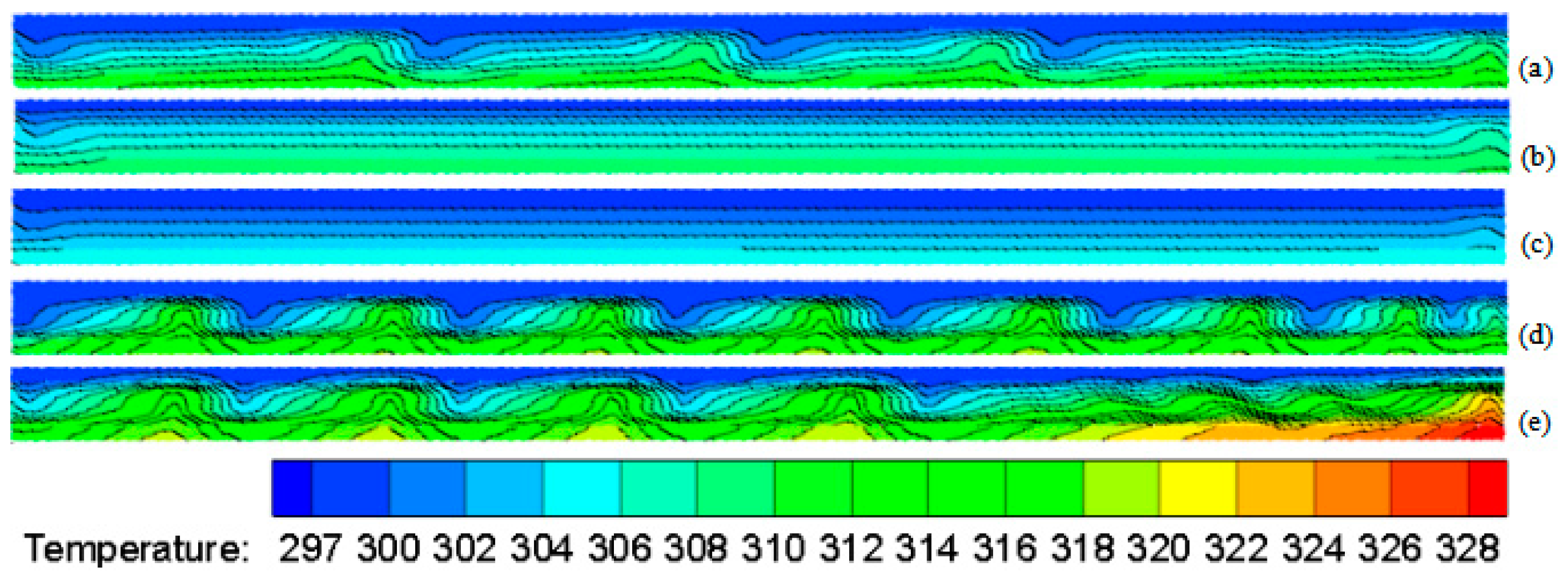
The temperature distribution in the 15 mm thick cavity at 30° under different heat flux densities and system emissivities are given in
Figure 9.
Figure 9c is the temperature distribution in the cavity without aluminum foil on the inner wall at 25.2 W/m
2, and it indicates that the temperature difference is small and that only conduction is observed. The hot surface temperature of the cavity and the temperature gradient increase when the heat flux density is increased from 25.2 W/m
2 to 91.84 W/m
2.
Figure 9a is the temperature distribution in the cavity without aluminum foil on the inner wall at 91.84 W/m
2, and it indicates that as the hot surface temperature increases, convection and conduction occur. After pasting the aluminum foil, the thermal resistance, hot surface temperature and cavity temperature gradient all increase dramatically at the same flux density. The aluminum foil effect in CWSA is slightly greater than that in CWDA.
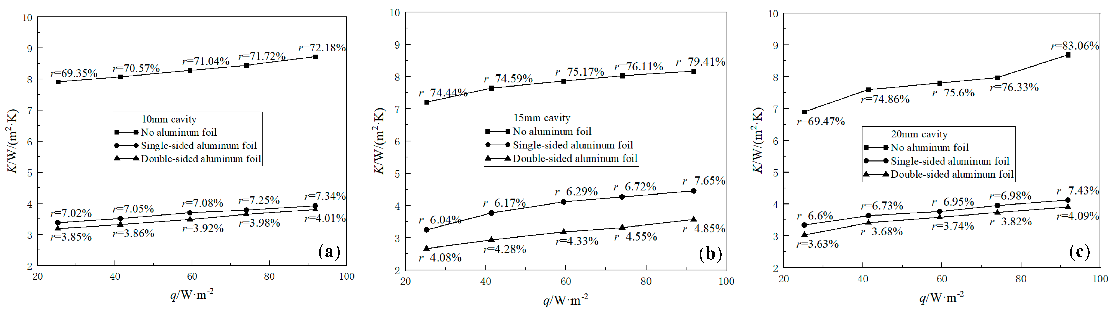
Figure 10 shows the equivalent heat transfer coefficient
K and its radiation share
r of the cavities with 10 mm, 15 mm and 20 mm thicknesses at 30° inclination when the heat flux density is increased from 25.2 W/m
2 to 91.84 W/m
2. The change trends and their reasons in the cavities at 30° are similar as that in horizontal cavities, but the corresponding values are lower.
The average values (W/(m2·K)) and (%) are 8.29/70.97, 7.78/75.94 and 7.8/75.86 in CWOA with 10 mm, 15 mm and 20 mm thickness, respectively; 3.66/7.15, 3.97/6.57 and 3.77/3.92 in CWSA and 3.49/3.92, 3.13/4.42 and 3.54/3.79 in CWDA. The changes in and with the cavity thickness are irregular because the effect of convection and radiation included in the heat transfer are changed when the cavity thickness is different.
Compared with CWOA, after pasting the aluminum foil, and values in CWSA with 10 mm, 15 mm and 20 mm thicknesses are reduced by 56%/90%, 49%/91% and 52%/91%, respectively, and that of the cavity with double-sided aluminum foil are 58%/95%, 60%/94% and 55%/95%, respectively.
3.5.2. Cavity Angle Effect
Based on the above model and method, the heat transfer processes in the cavities at 45° and 60° are numerically calculated, and the detailed information is summarized in
Table 4.
The value of the same cavity at 0° is the largest one because the convection effect could be the strongest, while the second largest is in the cavity at 90°, and the value of the same cavity at 45° is the minimum. The change of is irregular when the cavity angle and the cavity thickness are changed, but it is usually inverse to the change in .
In CWSA at 30°, the maximum of and the minimum of are in the cavity with 15 mm thickness, while in CWSA at 45°, CWDA at 30° and CWDA at 45°, the minimum of and the maximum of are in the cavity with 15 mm thickness. Except for the above, in all other cavities at any angle, decreases and increases when the thickness is increased.
4. Conclusions
Because the vehicle/train envelope is filled with a large number of narrow cavities, enhancing the thermal resistance of these cavities is helpful for improving the insulation characteristics of the envelope. This paper provides an effective and feasible method to enhance the thermal resistance of a narrow cavity by pasting on aluminum foil, and combined experimental and numerical methods were employed to demonstrate its effect. The following conclusions can be drawn:
- (1)
The radiation effect on the cavity heat transfer is significant in the narrow closed cavity enclosed by conventional material, such as the vehicle/train envelope material. The system emissivity and the radiation heat transfer share of the cavity mentioned in this paper are 0.941 and 70%, respectively.
- (2)
Compared with the heat transfer of the narrow cavity made of conventional materials, after pasting aluminum foil or a similar coating to the inner wall of the cavity mentioned in this paper, the radiation share is decreased to less than 5% and the equivalent heat transfer coefficient is reduced by more than 50%.
- (3)
The method mentioned in this paper could be a reference to improve traffic energy consumption and thermal comfort.
Author Contributions
Methodology, W.-H.Z., L.S. and S.-S.L.; Validation, L.S.; Investigation, S.-S.L.; Writing—original draft, L.S.; Writing—review & editing, W.-H.Z.; Supervision, W.-H.Z., S.-S.L. and J.-Y.W.; Funding acquisition, W.-H.Z. All authors have read and agreed to the published version of the manuscript.
Funding
This research received no external funding.
Data Availability Statement
Not applicable.
Conflicts of Interest
The authors declare no conflict of interest.
Nomenclature
| Ra | Rayleigh number |
| Re | Reynolds number |
| Nu | Nusselt number |
| Pr | Prandtl number |
| I | Wire resistance, m2·K/W |
| T | Temperature, K |
| Thm | Hot surface temperature, K |
| Tlm | Cold surface temperature, K |
| ξ | Wire temperature coefficient of resistance, m2·K/W |
| K | Equivalent heat transfer coefficient, W/(m2·K) |
| r | Radiation heat transfer share |
| qh | Conduction heat flux, W/m2 |
| qc | Convection heat flux, W/m2 |
| qr | Radiation heat flux, W/m2 |
| εs | Emissivity of narrow cavity, W/(m2·K4) |
| δw | Thickness of the cavity, m |
| CWOA | Cavity without aluminum foil |
| CWSA | Cavity with single-sided aluminum foil |
| CWDA | Cavity with double-sided aluminum foil |
| u | Velocity components, m/s |
| v | Velocity components, m/s |
| p′ | Effective pressure, kg/(m·s2) |
| ρ | Density, kg/m3 |
| g | Gravitational acceleration, m/s2 |
| β | Coefficient of thermal expansion, m2/s |
| v | Coefficient of viscous diffusion, m2/s |
| a | Coefficient of thermal diffusion, m2/s |
| λ | Thermal conductivity, W/(m·K) |
| ∆ | Difference value |
References
- Li, S.; Zhou, W.; He, X.; Wang, L. Experimental study on improving thermal resistance of vertical enclosures based on radiation principle. J. Radiat. Res. Radiat. Process. 2017, 35, 020801. [Google Scholar]
- Rincón-Casado, A.; Sánchez de la Flor, F.J.; Chacón Vera, E.; Sánchez Ramos, J. New natural convection heat transfer correlations in enclosures for building performance simulation. Eng. Appl. Comput. Fluid Mech. 2017, 11, 340–356. [Google Scholar] [CrossRef]
- Hinojosa, F.J.; Alvarez, G.; Estrada, A.C. Three-dimensional numerical simulation of the natural convection in an open tilted cubic cavity. Rev. Mex. Fís. 2006, 52, 111–119. [Google Scholar]
- Saury, D.; Rouger, N.; Djanna, F.; Penot, F. Natural convection in an air-filled cavity: Experimental results at large Rayleigh numbers. Int. Commun. Heat Mass Transf. 2011, 38, 3–19. [Google Scholar] [CrossRef]
- El-Sherbiny, S.M.; Hollands, K.G.T.; Raithby, G.D. The effect of thermal boundary conditions on natural convection in vertical and inclined air layers. J. Heat Transf. 1982, 104, 515–520. [Google Scholar] [CrossRef]
- Kim, D.M.; Viskanta, R. Effect of wall conduction and radiation on natural convection in a rectangular cavity. Numer. Heat Transf. 1984, 7, 449–470. [Google Scholar] [CrossRef]
- Zhan, N.Y.; Yang, M.; Wei, X.P. Numerical study of thermal radiation in enclosure coupled with natural convection heat transfer. Chin. Sci. 2010, 40, 1052–1060. [Google Scholar]
- Navarro, J.; Hinojosa, J.F.; Pia-Ortiz, A. The effect of surface thermal radiation on heat transfer in a ventilated cavity. J. Heat Transf. 2020, 143, 012801. [Google Scholar] [CrossRef]
- Ismael, M.A.; Armaghani, T.; Chamkha, A.J. Conjugate heat transfer and entropy generation in a cavity filled with a nanofluid-saturated porous media and heated by a triangular solid. J. Taiwan Inst. Chem. Eng. 2016, 59, 138–151. [Google Scholar] [CrossRef]
- Mezrhab, A.; Bouali, H.; Amaoui, H. Computation of combined natural-convection and radiation heat-transfer in a cavity having a square body at its center. Appl. Energy 2006, 83, 1004–1023. [Google Scholar] [CrossRef]
- Gibanov, N.S.; Sheremet, M.A. Numerical investigation of conjugate natural convection in a cavity with a local heater by the lattice boltzmann method. Fluids 2021, 6, 316. [Google Scholar] [CrossRef]
- Yang, Q.S.; Hu, C.H.; Xu, Z.X. Research on coupled conduction and radiation heat transfer in a two-dimensional rectangular enclosed cavity. J. Shanghai Jiao Tong Univ. 1993, 47–56. [Google Scholar]
- Hu, S.T.; Lian, L.; Li, L. Study on thermodynamic force and flow in the process of compound heat transfer in a closed cavity. J. Harbin Univ. Civ. Eng. Archit. 1999, 68–71. [Google Scholar]
- Yang, G.; Wu, J.Y. Effects of natural convection, wall thermal conduction, and thermal radiation on heat transfer uniformity at a heated plate located at the bottom of a three-dimensional rectangular enclosure. Numer. Heat Transf. Part A Appl. 2016, 69, 589–606. [Google Scholar] [CrossRef]
- Zhao, Z.W.; Li, B.W.; Wu, W.F.; Li, Y.K.; Cang, D.Q. A Hybrid simulation method for radiative heat transfer. J. Univ. Sci. Technol. Beijing 2005, 4, 423–426. [Google Scholar]
- Moutaouakil, L.E.; Zrikem, Z.; Abdelbaki, A. Interaction of surface radiation with laminar and turbulent natural convection in tall vertical cavities: Analysis and Heat Transfer Correlations. Heat Transf. Eng. 2015, 36, 1472–1484. [Google Scholar] [CrossRef]
- Kuznetsov, G.V.; Nee, A.E. Conduction, convection, and radiation in a closed cavity with a local radiant heater. Front. Heat Mass Transf. 2018, 10, 26. [Google Scholar]
- Rehhali, K.; Hasnaoui, M.; Raji, A. Lattice boltzmann approach for natural convection and radiation in a tilted square cavity. J. Thermophys. Heat Transf. 2019, 33, 322–333. [Google Scholar] [CrossRef]
- Li, S.; Zhou, W.H.; Wang, L.B. Experimental study of thermal resistance enhancement measures for narrow vertical closed cavities based on radiation principle. J. Radiat. Res. Radiat. Process. 2017, 35, 58–66. [Google Scholar]
- Ma, X.J. Experimental and Numerical Study of Aluminum and Multi-Layer Coupled Panels Heat Insulation Properties; Lanzhou Jiao Tong University: Lanzhou, China, 2014. [Google Scholar]
- Moffat, R.J. Contributions to the theory of single-sample uncertainty analysis. J. Fluids Eng. 1982, 104, 250–258. [Google Scholar] [CrossRef]
- Patankar, S.V. Numerical Heat Transfer and Fluid Flow; Hemisphere: New York, NY, USA, 1980; pp. 330–351. [Google Scholar]
- Tao, W.Q. Numerical Heat Transfer, 2nd ed.; Xi’an Jiao Tong University Press: Xi’an, China, 2001. [Google Scholar]
| Disclaimer/Publisher’s Note: The statements, opinions and data contained in all publications are solely those of the individual author(s) and contributor(s) and not of MDPI and/or the editor(s). MDPI and/or the editor(s) disclaim responsibility for any injury to people or property resulting from any ideas, methods, instructions or products referred to in the content. |
© 2023 by the authors. Licensee MDPI, Basel, Switzerland. This article is an open access article distributed under the terms and conditions of the Creative Commons Attribution (CC BY) license (https://creativecommons.org/licenses/by/4.0/).


