1. Introduction
Technological progress continues yearly, consuming more electricity and making it necessary to increase energy production. The conservative approach based on the use of fossil fuels is becoming less and less appropriate due to the rapid depletion of their reserves. Political pressures also emphasize the use of so-called green energy based on renewable sources such as the sun or wind. From a practical point of view, a perfect example of this is the successive increase in the number of photovoltaic power plants. Until recently, they were built on a small scale for individual use. However, decreased production costs and their increasingly widespread availability have meant that their areas are noticeably more extensive today, and the peak power generated reaches hundreds of megawatts. Unfortunately, the current problem is the requirement for a sufficiently large area of land, which may affect production, maintenance, and the return on investment costs.
A way to solve this problem may be to use artificial water reservoirs which are often created as wastelands for industrial or mining activities. As a remnant of industrial processes, such a reservoir may be excluded from recreational use for many years and considered a landscape nuisance. Therefore, the cost of renting such unusable land for constructing a floating photovoltaic power plant may be significantly lower than that typical for usable land. In addition, this type of investment can contribute to the energy development of the local community, which is an essential point of local social policy. On the other hand, some technical challenges should be expected due to the specific location of the facility on the water surface, especially in the context of lightning.
The first problem may be inconsistency at the level of global standardization in the selection of coefficients determining the level of lightning hazard. It can be seen by comparing two standards, the IEC 62305 [
1] and NTC 4552 [
2], which interpret the electro-geometric model of lightning discharge slightly differently. The second problem may be the diversity in the density of ground discharges, which directly translates into the level of lightning hazard [
3]. In such situations, modeling and simulation analysis, e.g., field analysis using environments such as Ansys, can effectively help solve these problems.
The use of computer simulations as an experimental environment is widespread because they allow for faster and more effective testing and verification of the various cases that may occur in reality [
4,
5]. Instead of running many experiments, which can be costly and time-consuming, computer simulations might simulate different assumptions and test configurations. This makes it possible to analyze many variants in less time, leading to faster innovation or the definition of new assembly and operating standards. They also allow for more accurate studies that may be difficult or impossible to carry out using physical experiments, such as the simulations with a layer of ice on the surface of the water presented below. The vast majority of publications devoted to photovoltaic installations focus on micro-installations mounted on the roofs of buildings or ground installations. It is not easy to find publications referring to the floating solutions that are gaining popularity. Hence, well-thought-out differences in threats and developed protective solutions are necessary.
2. Fundamental Model
The computer simulations presented below were performed in the Ansys/Maxwell 3D environment and they concerned individual elements of the lightning protection system, i.e., lightning rods, down conductors, and the earthing system. The Heidler function with the following parameters was used to describe the shape of the lightning current: peak value
Im = 40 kA, rise time
T1 = 10 µs, and tail time
T2 = 350 µs (
Figure 1).
Depending on the type of discharge (bottom-up or top-down), its polarisation (positive or negative), and time positioning (first, subsequent, or long-lasting), the above parameters may become different values [
1].
The basic model used for the analysis was based on a fragment of a larger photovoltaic installation and consisted of two rows of supporting structures with two so-called tables. The assumption for the tests was to connect to the lower pair of tables’ lightning rods as the integrated configuration (
Figure 2).
The entire conductive structure was placed in the air and its base was based on a material with electrical parameters corresponding to water. Some parts of the model, such as the grounding, had variable parameters during the simulation and are described in the following sections of this article.
3. Lightning Threat
The lightning threat for floating photovoltaic power plants results from several factors. The first is its location in an open area, which is the surface of a water reservoir. In addition, the upper edges of the photovoltaic modules, mounted at an angle on the supporting structures due to edges with a minimal rounding radius, are places of concentration for the electric field, which increases the probability of being struck by lightning. An example of the electric field distribution between the base of a storm cloud and the ground level, especially near the sharp edges of the photovoltaic modules, is shown in
Figure 3.
As can be seen, each sharp edge is a potential place where lightning could be attracted. Despite the relatively diminutive height, due to the large surface area, the area for collecting direct lightning discharges is also larger, which makes a lightning protection installation an essential safety system element.
There is also a common belief that water attracts lightning. It may seem true at first glance, but a more plausible explanation is that any vessel on a lake causes an increase in the electric field strength due to its design, leading to an increased likelihood of being struck by lightning. Records of lightning discharge in the region of the largest lake in Poland, Śniardwy, and the surrounding ground areas conducted by the LINET Lightning Detection Network in 2019–2021 do not confirm this thesis (
Figure 4).
The lightning risk assessment procedure for a floating photovoltaic power plant does not differ from that described in the international standard IEC 62305-2 [
6]. Since a free-standing photovoltaic power plant is a specific facility due to its geometry, function, and location on the surface of a water reservoir, such a general approach will not always lead to the selection of the optimal method of lightning and surge protection. Due to its constant contact with water, such a structure should meet additional requirements regarding the electromechanical strength of the construction material, particularly corrosion resistance. Corrosion is a significant factor in the case of a power plant located in salt water on the sea.
The considerations presented below refer to the broadly understood impact of various factors on the effectiveness of lightning and surge protection on a floating photovoltaic power plant.
4. Lightning Rods
One of the most common problems related to lightning protection is the method of mounting lightning rods. Technically, there are two possibilities: free-standing or integrated into constructed support tables (
Figure 5) [
5,
7,
8].
Both solutions have positive and negative effects. Using separate lightning rods means they are placed next to the support table at a distance that meets the minimum separation distance requirement calculated according to the standard [
7,
8]. Still, at least
s = 0.5 m [
9,
10] is recommended to minimize the risk of sparking on the protected structure.
On the one hand, the rods mounted as a standalone minimize the impact of the direct flow of a lightning current through the supporting structure. Still, on the other hand, flowing entirely to the ground can cause significant magnetic field values, resulting in a high, probably significant value of voltages induced in the electrical installation.
The choice of rods integrated with the supporting structure causes the lightning current to dissolve but may cause mechanical and thermal exposures. On the other hand, the lower current intensity values in individual elements and different geometric arrangements may reduce the voltages induced in the electrical installation. This method is also cheaper to implement than standalone rods and eliminates potential problems with the communication routes between supporting structures.
A lightning equalization system should galvanically connect all conductive construction elements placed on individual floats to avoid dangerous sparking. The joints should meet the normative and technical requirements mentioned above, but using conductors with a rectangular cross-section shape is recommended. Such a conductor is characterized by a lower inductance than a conductor with a circular cross-section. In the case of lightning current, its surge nature and very high steepness are essential for implementing the goal of equalizing potentials.
A separate requirement is the mechanical and thermal coordination of lightning protection system elements with the thermal properties of the floats. Resistance heating occurs in each element, conducting a significant part of the lightning current. It may cause a sharp increase in the temperature of the conductive elements, which in contact with the plastic structure of the float, may result in its melting and sinking or fire. The temperature of LPS wires can be determined from the following dependencies:
where
—temperature increase in wires {K}, α—resistance temperature coefficient {1/K},
W/
R—specific energy of the current pulse {J/Ω},
—resistivity of the wire at ambient temperature {Ωm},
q—cross-sectional area of the conductor {m
2},
—material density {kg/m
3},
Cw—thermal capacity {J/kgK},
Cs—hidden melting heat {J/kg}, and
—melting point {°C}.
Depending on the cross-section of the conductor, its material and lightning current peak value temperature might rise to tens of Celsius degrees, which may lead to mechanical deformations and the destruction of its cable insulation. The same influence might be observed on lightning current floats with supporting structure-conducted elements (
Table 1).
In addition to the thermal aspects mentioned above, the mechanical strength and durability criteria should be considered for parts exposed to changing weather conditions and corrosion. The current lightning dynamics cause the formation of electrodynamic forces that can lead to the dismount wires being torn out of their mounts on plastic floats, which can then cause their sinking.
The electrodynamic forces caused by the current flowing in a conductor containing long parallel segments of length
l and a distance of
d (long and narrow loop) can be calculated approximately using the following equation [
7]:
where
F(
t)—electrodynamic force {N},
i—current {A},
—magnetic permeability of vacuum {H/m},
l—wire length {m}, and
d—spacing between wires {m}.
The elements connecting adjacent wires to the remaining LPS wires are potentially weak points where very high mechanical and thermal stresses can occur. Laboratory tests have shown that separating each effect from the others is difficult because of a complex synergistic effect. Mechanical strength depends on the local smelting of the contact surface. The relative displacements of the connection elements favor the development of electric arcs and indirect intensive heat generation.
A detailed analysis in this direction with additional simulations is described in [
9,
10].
5. Lightning down Conductors
Another aspect of lightning protection, after the discharge is taken over, is the discharge of the lightning current to the ground. In the case of a free-standing photovoltaic power plant, this function can be performed by dedicated down conductors, e.g., conductors attached to free-standing lightning rods, and natural elements, such as a conductive supporting structure. Both cases should ensure galvanic continuity at the lowest possible impedance and represent a sufficiently high resistance to the thermal and electromechanical effects of a flowing lightning current as well as have the anti-corrosion properties necessary for a structure placed on water. They should also ensure compliance with normative requirements, e.g., requirements regarding geometric dimensions [
7,
11]. This is essential because such floating structures are mounted on insulating materials. Thus, current flow can damage and, in extreme cases, initiate the process of drowning the object.
In the case of a direct lightning discharge into a lightning protection system, the value of its electrical potential and the conductive installations connected to it increases significantly. This value directly results from electrical parameters such as resistance and inductance, and, above all, from the earth resistance value. A series of experiments based on modeling and simulations resulted in the spatial distributions of electric and magnetic fields around the modeled structures that were conducted to show the importance of these aspects. Both aspects have been described in detail in [
9,
10,
12,
13,
14], therefore, only sample results are presented in this article.
The fundamental model of the installation is shown in
Figure 2. The analyses carried out were static characters: electrostatic and magnetostatic. Time parameters were based on assumed surge rising time. An example result of the electric field analysis in case of a direct lightning strike is shown in
Figure 6. The value of air electrical conductivity was assigned σ = 10
−14 S/m [
15].
Based on the results obtained from this experiment, it is possible to assess the necessity for lightning safety parameters as an insulation gap to ensure the absence of dangerous flashovers from the lightning protection system to other conductive objects or installations, such as the conductive parts of a telecommunications shaft.
Simulating the magnetic field is essential because its steepness determines the voltages induced in photovoltaic installations, particularly in DC circuits. The sample result is shown in
Figure 7.
Based on the spatial distribution of the magnetic field and the knowledge of its rate of change, it is possible to estimate the expected values of the induced voltages (
Figure 8). This voltage can be calculated using the formula:
where
Uind—induced voltage {V},
S—the surface area created by installation wires {m
2},
—magnetic field induction vector perpendicular to surface
S{T}, and
dT—surge rising time {s}.
Due to the specificity of free-standing photovoltaic power plants, in particular in floating configurations, the above issues are fundamental.
Metal ducts for routing power installations should ensure galvanic continuity and be effectively connected to the earthing system. They can be used as potential equalization if the condition of the minimum thicknesses for lightning current discharge is met.
6. Grounding
A floating photovoltaic power plant is also a unique facility for the sake of the grounding system. Although water has suitable electrical conductivity parameters, the traditional form of lattice earthing made with a flat steel bar may be difficult to implement due to its weight. For this reason, other possibilities for implementing this installation should be considered, such as anchoring connections with the bottom or vertical earthing submerged under the water surface. Additional factors should be also considered when designing this installation, such as the reservoir becoming overgrown with algae in the summer, freezing in the winter, or its changing water levels throughout the year. The variability of these values causes several technical challenges in ensuring safe earthing, not only as part of the lightning protection system but also as part of the electric shock protection system.
6.1. Modeling and Simulations
Exemplary simulation tests were conducted to compare various earth electrode forms, mainly lattice and frame earth electrodes, and were supplemented with additional vertical earth electrodes. In each case, the result was the electric potential distribution on the water’s surface. This value determines the values of shock voltages and other electric exposures listed further in the text.
In terms of the influence of the mesh size of the lattice, simulations were performed for two configurations with different mesh sizes:
A mesh size of a = 5 m;
A mesh size of a = 10 m.
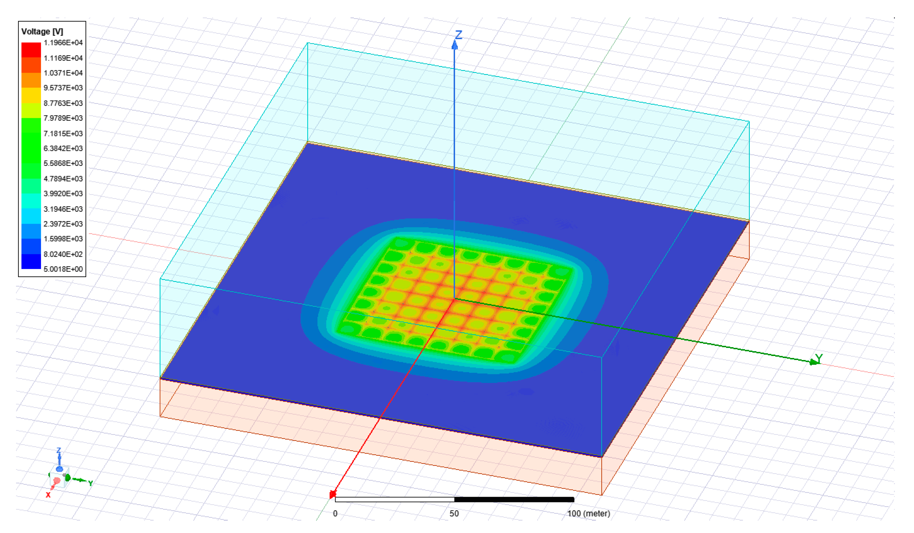
In the beginning, the earthing was placed inside the water, to which a conductivity value of
σ = 0.01 S/m and a lightning current peak value of
Iimp = 40 kA was supplied to the chosen point (e.g., the lightning protection mast). The value of the immersion depth was defined as
h = 0.6 m (
Figure 9).
In addition to the lattice-type earthing, simulations were performed for the frame-type earthing model. This model is presented in
Figure 10.
Such a frame is a specific alternative to the lattice because it lacks inner connections and is considered one large eye. It simulated two versions that also differ in size:
l = 30 m and
l = 60 m. The exemplary simulation results for the lattice-shaped configuration are shown in
Figure 11.
Based on the results obtained for these configurations, similarities in the distribution of electric potential can be found. However, apparent differences can also be seen, e.g., in terms of maximum values. A larger grid disperses the lightning current over a larger area and is associated with lower electric potential peaks at the water surface. This situation leads to lower electrical stresses for the electrical installation and the conductive elements of the floating and load-bearing structure. It is also a more advantageous configuration in case of electric shock hazards to personnel who may be present in the power plant area.
The potential distributions shown in
Figure 12 are presented for the framed configuration. As seen in this case, the larger size positively affects the peak values of the potentials on the water surface.
Comparing the results of both test configurations, it should be stated that the mesh earthing is undoubtedly more advantageous due to the lower values of the electric potential on the water surface, and its lower drop translates into better electrical safety.
As the second part of the research, a simulation was carried out based on models shown in
Figure 9 and
Figure 10. This time, the models were equipped with additional vertical pins mounted at corner intersections, whose length was assumed as 5 m each (
Figure 13). In this test, the horizontal parts of each configuration were placed above the water surface and interpreted as an equipotential bonding.
The exemplary results obtained for frame-type earthing with spacing sizes equal to
l = 30 m and
l = 60 m are presented in
Figure 14. The water’s electrical parameters were assumed the same way as in earlier models.
When comparing the results obtained in this test with those obtained during earlier tests for installations submerged under the water surface, a considerable difference in the maximum electric potential values at the water’s surface might be observed. This phenomenon causes the occurrence of step voltages in the places of assembly of vertical elements. To protect against the electric shock caused by lightning currents during direct lightning discharges into the power plant’s structural elements, warning signs prohibiting staying in its open space should be placed at the entrances to the power plant area.
For verification purposes, additional simulations were performed for the extended configuration given in the previous test, which might be interpreted as the extended area of the floating photovoltaic power plant (
Figure 15). In this case, the vertical pins were distributed more extensively. Furthermore, in this case, only vertical pins were placed in the water and the horizontal part of the installation stayed over the water’s surface.
The results obtained for the electrical potential on the water surface are presented in
Figure 16. As seen with the more extensive design, the maximum potential value on the water’s surface has been significantly reduced.
6.2. Effects of Water Freezing
The last simulation concerned the impact of water freezing (
Figure 17). For this purpose, the base models (
Figure 9 and
Figure 10) were supplemented with an additional, near-surface layer of ice corresponding to an electrical conductivity
σ = 0.0002 S/m. Its thickness was defined as
hice = 1 m, and the immersion depth of the horizontal configurations was assumed to be
h = 0.6 m frames with a dimension of
l = 60 m.
It should be noted that the effectiveness of the ground placed inside the ice layer drastically loses effectiveness. Such a situation may increase the risk of electric shock, electrical stress, and electrodynamic forces acting on conductive elements. The act of freezing also causes the formation of mechanical forces directed towards the water surface, which also loads the power plant’s load-bearing structure, particularly in the places where the earthing systems are connected.
The last investigated configuration was the earthing setup, shown in
Figure 15, but with a layer of ice (
hice = 1 m). The results obtained for a mesh size of
a = 10 m are presented in
Figure 20.
Comparing these results with those obtained for the configuration without the ice layer, the maximum electric potential values at the water surface are very similar. This leads to the conclusion that such a grounding configuration consisting of numerous vertical elements immersed in water is optimal for this type of construction, both for electrical and mechanical reasons.
7. Summary and Conclusions
Summarizing the above considerations, the design of a lightning protection installation with significant earthing installation should include the above analysis of factors. These installations are critical due to the electrical safety of the installation, devices, and, especially, technician personnel.
Regarding choosing the most technically and economically optimal ground system for lightning protection, it seems that having only vertical pins with lengths of at least 5 m deep inside water and evenly distributed throughout the photovoltaic island is ideal. Each of them should be effectively galvanically connected to obtain an equipotential effect.
Such an even distribution ensures the optimal division of a lightning current and its discharge into the water, where it is dispersed.
Figure 21 shows the step voltage distributions around the vertical earthing for a spacing of
l = 15 m and
l = 30 m. This information is valuable for selecting the type of earthing and its geometry, which is particularly important in a floating photovoltaic power plant. In addition to electrical parameters, several other factors should be taken into account, such as the weight of the structure and its durability, as well as the highly dynamic phenomena resulting from the flow of a lightning current.
Due to the peculiarities of the reservoir, the depth of which decreases at the shore, the vertical pins nearest the shore may be shorter, which should not reduce the effectiveness of the grounding. Moreover, earthing, such as the lattice or frame analyzed above, is a structure characterized by significant weight and a very troublesome method of assembly, which is associated with a much higher cost of execution and a higher probability of assembly errors negatively affecting the effectiveness of the operation.
When performing this type of grounding system, it is necessary to ensure the galvanic continuity of equalization connections between individual vertical earthing which can be implemented above the water surface, e.g., with the use of conductive cable troughs, or below the water surface, e.g., with the use of band-iron. These connections must meet the IEC 62561-2 [
16] requirements and PN-EN 62305-3 [
7] resistance to partial lightning currents.
Particularly interesting and worth considering, as they are likely to be implemented in the future construction of offshore photovoltaic power plants [
17] but also potentially dangerous, is the case for transformer stations also located on the water. However, the current regulations [
11] are not suitable for the technical conditions prevailing at sea. Hence, analyses such as those presented in this article can be extremely helpful in extending them to such cases.


