Article

Horizontal Vibration Characteristics of a Tapered Pile in Arbitrarily Layered Soil

1
Faculty of Engineering, Zhejiang Institute, China University of Geosciences, Wuhan 430074, China
2
Guangxi Key Laboratory of Disaster Prevention and Engineering Safety, College of Civil Engineering and Architecture, Guangxi University, Nanning 530004, China
3
Research Center of Coastal Urban Geotechnical Engineering, Zhejiang University, Hangzhou 310058, China
*
Authors to whom correspondence should be addressed.
Energies 2022, 15(9), 3193; https://doi.org/10.3390/en15093193
Submission received: 6 February 2022 / Revised: 6 April 2022 / Accepted: 11 April 2022 / Published: 27 April 2022

Abstract

:
A tapered pile (TP) is a new type of pile with a good bearing capacity, and scholars have conducted in-depth research on its static bearing characteristics. However, there is relatively little research on its dynamic bearing characteristics. In this paper, the horizontal vibration behavior of a tapered pile in arbitrarily layered soil is studied. Utilizing the Winkler foundation model and Timoshenko beam model to simulate pile-surrounding soil (PSS) and a tapered pile, respectively, the horizontal vibration model of a tapered pile embedded in layered soil was built. The analytical solutions for the horizontal displacement (HD), bending moment (BM), and shear force (SF) of a tapered pile were derived, and then the solutions for the horizontal dynamic impedance (HDI), rocking dynamic impedance (RDI), and horizontal-rocking coupling dynamic impedance (HRDI) of pile head were obtained. Using the present solutions, the effects of soil and pile properties on the horizontal vibration characteristics of a tapered pile were systemically studied. The ability of a tapered pile–soil system to resist horizontal vibration can be improved by strengthening the upper soil, but this ability cannot be further improved by increasing the thickness of the strengthened upper soil if its thickness is greater than the critical influence thickness.

1. Introduction

A tapered pile is often utilized to replace the conventional cylindrical pile (CP) because of its good bearing capacity for wind farms, port engineering and other projects dominated by horizontal loads. Experiments conducted by El Naggar and Wei [1,2], as well as Ghazavi and Ahmadi [3], showed that the horizontal and axial bearing capacities of TPs increased by 77% and 80%, respectively, compared with those of a CP with the same length and volume. The static bearing characteristics of TPs have been thoroughly investigated by many researchers [4,5,6,7,8]. In addition to bearing static loads, the TP is also often subjected to dynamic loadings arising from traffic, wind, waves, machine vibrations and seismic loadings, etc. Therefore, the dynamic characteristics of TPs are experiencing an increasing research interest.
Over the past decades, many scholars have paid attention to the vertical and torsional dynamic analysis of TPs. Saha and Ghosh initially developed a finite difference model to study the vertical vibration behavior of TP [9]. Xie and Vaziri presented a numerical integration method for analyzing the response of TPs to vertical vibrations [10]. Ghazavi compared the vertical dynamic characteristics of TPs and CPs under different end-bearing conditions [11]. Wu et al. established an analytical model to investigate the construction effect on the vertical dynamic response of a TP [12], where the disturbed soil is simulated by the radially inhomogeneous soil model [13,14,15,16,17,18,19]. Wang et al. extended Wu’s study to the saturated soil case by introducing the fractional constitutive model [20]. Bryden et al. proposed a simple approximate method to quickly obtain the vertical stiffness and damping coefficients of TPs [21]. The study indicated that the resonant amplitude of a TP during vertical vibrations could be significantly decreased as its cone angle increased. As the material damping is often neglected in existing theoretical models for simplicity, Bryden et al. also proposed an analytical model to quantitatively study the effect of material damping on the vertical dynamic response of TPs [22]. The results indicated that the omission of the material damping would cause an overestimation of the resonant amplitude and the underestimation of the resonant frequency. Wu et al. first proposed the circumferential shear complex stiffness transfer model to investigate the influence of the construction disturbance effect on the torsional dynamic response of TPs [23]. Furthermore, Guan et al. theoretically studied the torsional vibration characteristics of TPs by taking both the compaction effect of PSS and the stress diffusion effect of pile end soil into account [24].
Compared with the significant achievements in the vertical and torsional dynamic analysis of TPs, the relevant literature on the horizontal dynamic characteristics of TPs is limited. Ghazavi used a two-phase analysis method to evaluate the horizontal dynamic behavior of a TP caused by kinematic seismic loading due to earthquakes [25]. Lee et al. assumed that a TP would behave as a vertical-loaded horizontal Euler–Bernoulli (EB) beam and investigated the influence of longitudinal loading on the transverse free vibration of TP [26]. It was found that the natural frequency significantly decreased with the increasing axial loading and tapered angle. The EB beam model is verified to be reasonably accurate for long or slender piles. However, for short stubby piles, the application of an EB beam model is doubtful because it does not consider the influence of shear displacement and rotatory inertia of pile body. Gupta and Basu compared the applicability of Timoshenko (TS), EB and rigid beam models in the analysis of piles that encountered horizontal static or dynamic loads [27,28]. They verified that the TS beam model could achieve a satisfactory accuracy in the cases of all horizontally loaded piles, while the EB beam model was most suitable for solid cross-section piles with a large slenderness ratio. Ding et al. [29] and Zheng et al. [30] studied the influence of longitudinal loading on the horizontal vibration characteristics of pipe plies with the EB and TS beam models, respectively. It was shown that the EB beam model overestimated the horizontal impedance of pile and the loading effect.
Reviews of the literature show that the existing research is mainly based on EB beam models for studying the horizontal vibration characteristics of a TP. However, a TP is a typical stubby pile with its radius decreasing linearly with depth; additionally, the tapered angle will also make pile–soil dynamic interaction more complicated. The application of an EB beam model for predicting the horizontal behavior of a TP is still questionable and needs to be calibrated [14,18]. In this study, analytical solutions for TP-encountered horizontal dynamic loads are derived with the TS beam model. The influences of soil and pile properties on the horizontal vibration characteristics of TPs are investigated based on the present solutions. A systematic parametric study is carried out to evaluate the performance and accuracy of EB and TS beam models for a TP subjected to horizontal dynamic loads. The results of this work may benefit other researchers working on the monitoring or evaluation of the TP–soil system used in construction when there are horizontal dynamic loads acting on the TP head.

2. Computational Model and Assumptions

The coupling horizontal vibration model of TP embedded in arbitrarily layered soil is depicted in Figure 1, where the pile is simulated by TS beam model and the PSS is simulated by the Winkler foundation model, respectively. The pile head bears a harmonic horizontal dynamic load F ( t ) = Q 0 cos ω t , whose amplitude is Q 0 . ω is the circular frequency. The length and cone angle of TP are denoted by θ and L , separately. d 1 represents the diameter of pile head. The z-axis coincides with the downward pile axis. Considering the variable section of TP and the layered characteristics of PSS, the TP–soil system is divided into n segments in the z-axis, which are numbered by 1, 2, …, j, …, n from pile head to pile bottom. l j and h j represent the thickness and top surface depth of the jth TP–soil system, respectively. When the number of segments n is large enough, each pile segment can be approximately regarded as a circular cross-section pile segment with equal diameter. In other words, if the number of segments n is large enough, the characteristics of the pile segment and surrounding soil layer are uniform with each pile segment, but may vary from segment to segment. k x j and c x j are the stiffness coefficient and damping coefficient of the soil acting on the shaft of the jth pile segment. According to the suggestion of Gazetas et al. [31], the values of k x j and c x j can be obtained as:
{ k x j = 1.2 E S j     c x j = 6.0 a j 1 4 ρ S j   V S j d j + 2 k x j β S j   ω
where V S j = G S j / 2 ρ S j ( 1 + ν S j ) , G S j , β S j , ρ S j and ν S j represent the shear wave velocity, shear modulus, damping ratio, density and Poisson’s ratio of the jth soil layer, respectively. d j = d 1 2 z tan θ represents the diameter of the jth pile segment. a j = ω d j / V S j is the dimensionless frequency of the jth TP–soil segment.
The analysis is conducted based on the following assumptions:
(1)
The TP is a viscoelastic frustum, and its diameter reduces linearly along the length direction.
(2)
To obtain the analytical solution for the established model, only the vertical load caused by the pile cap acting on the TP head is considered, and the interaction between the pile cap and its lower soil layer is not considered.
(3)
The pile-surrounding soil is arbitrarily layered soil, and each soil layer is homogeneous and isotropic, which can be regarded as a linear viscoelastic medium.
(4)
During horizontal vibration, the TP–soil system will undergo small deformations and strains.
(5)
The soil and pile are in completely continuous contact, and the pile cap effect is not considered.
(6)
During horizontal vibrations, the pile top does not rotate, and the pile bottom does not move because it is fixed by the bedrock.

3. Governing Equations and Their Solutions

The horizontal displacement (HD) and rotational angle (RA) of the jth pile segment are denoted by u j ( z , t ) and φ j ( z , t ) , respectively. Based on the TS beam model, the governing equations of the jth pile segment are:
k A P j G P j [ φ j ( z , t ) z 2 u j ( z , t ) z 2 ] + k x j u j ( z , t ) + c x j u j ( z , t ) t + m P j 2 u j ( z , t ) t 2 = 0
E P j I P j 2 φ j ( z , t ) z 2 + k A P j G P j [ u j ( z , t ) z φ j ( z , t ) ] = 0
where G P j = E P j / ( 2 ( 1 + ν P j ) ) , E P j , ν P j , m P j , A P j and I P j are the shear modulus, elastic modulus, Poisson’s ratio, mass, cross-section area and rotational moment of inertia of the jth pile segment. k denotes the shear shape factor, which is taken as 0.75 when the pile section is circular.
For steady-state harmonic vibrations, the variable separation method is introduced to solve Equations (2) and (3). If u j ( z , t ) = U j ( z ) e i ω t and φ j ( z , t ) = ψ j ( z ) e i ω t , these can be substituted into Equations (2) and (3) to yield:
k A P j G P j e i ω t [ d ψ j ( z ) d z d 2 U j ( z ) d z 2 ]   + U j ( z ) e i ω t [ k x j m P j ω 2 + i c x j ω ] = 0
E P j I P j e i ω t d 2 ψ j ( z ) z 2   + k A P j G P j e i ω t [ d U j ( z ) d z ψ j ( z ) ] = 0  
For simplicity, the following variables are introduced:
W P j = E P j I P j
J P j = k A P j G P j
k S j = k x j m P j ω 2 + i c x j ω
Substituting the above variables into Equations (4) and (5) gives:
W P j d 4 U j ( z ) d z 4 k S j W P j J P j d 2 U j ( z ) d z 2 + k S j U j ( z ) = 0
ψ j ( z ) = W P j J P j d 3 U j ( z ) d z 3 + ( 1 k S j W P j J P j 2 ) d U j ( z ) d z
Then, the general solutions of Equations (9) and (10) are obtained as:
U j ( z ) = e α j z ( A 1 j cos β j z + B 1 j sin β j z ) + e α j z ( C 1 j cos β j z + D 1 j sin β j z )
ψ j ( z ) = e α j z ( A 2 j cos β j z + B 2 j sin β j z ) + e α j z ( C 2 j cos β j z + D 2 j sin β j z )
where A 1 j , A 2 j , B 1 j , B 2 j , C 1 j , C 2 j , D 1 j and D 2 j are undetermined coefficients, and the coefficients α j and β j are written as:
α j = k S j 4 W P j + k S j 4 J S j
β j = k S j 4 W P j k S j 4 J S j
According to the theory of material mechanics, the bending moment (BM) amplitude and shear force (SF) amplitude are obtained as:
M j ( z ) = W P j d ψ j ( z ) d z = W P j [ e α j z ( A 3 j cos β j z + B 3 j sin β j z ) + e α j z ( C 3 j cos β j z + D 3 j sin β j z ) ]
Q j ( z ) = J P j [ d U j ( z ) d z ψ j ( z ) ] = W P j [ e α j z ( A 4 j cos β j z + B 4 j sin β j z ) + e α j z ( C 4 j cos β j z + D 4 j sin β j z ) ]
where A 3 j , A 4 j , B 3 j , B 4 j , C 3 j , C 4 j , D 3 j and D 4 j are undetermined coefficients.
The boundary conditions of the pile head bottom are derived as:
ψ 1 ( z ) | z = 0 = 0 ; Q 1 ( z ) | z = 0 = Q 0
U n ( z ) | z = L = 0 ; ψ n ( z ) | z = L = 0
The HD, RA, BM and SF at the interface of adjacent pile segments meet the continuous conditions, and their amplitudes are obtained as:
U j ( z ) | z = h j = U j + 1 ( z ) | z = h j
ψ j ( z ) | z = h j = ψ j + 1 ( z ) | z = h j
M j ( z ) | z = h j = M j + 1 ( z ) | z = h j
Q j ( z ) | z = h j = Q j + 1 ( z ) | z = h j
Transforming Equations (19)–(22) into a matrix relation gives:
T j ( h j ) X j = T j + 1 ( h j ) X j + 1
where the expressions of each matrix are expressed as:
T j ( h j ) = [ t 1 j t 2 j t 5 j t 1 j t 6 j t 2 j t 6 j t 1 j + t 5 j t 2 j t 7 j t 1 j t 8 j t 2 j t 8 j t 1 j + t 7 j t 2 j t 9 j t 1 j t 10 j t 2 j t 10 j t 1 j + t 9 j t 2 j t 3 j t 4 j t 5 j t 3 j t 6 j t 4 j t 6 j t 3 j t 5 j t 4 j t 7 j t 3 j + t 8 j t 4 j t 8 j t 3 j + t 7 j t 4 j t 9 j t 3 j t 10 j t 4 j t 10 j t 3 j t 9 j t 4 j ]
X j = [ A 1 j B 1 j C 1 j D 1 j ] T
where t 1 j = e α j z cos β j z , t 2 j = e α j z sin β j z , t 3 j = e α j z cos β j z , t 4 j = e α j z sin β j z , t 5 j = α j ( 1 k S j W P j J P j 2 ) + W P j J P j ( α j 3 3 α j β j 2 ) , t 6 j = β j ( 1 k S j W P j J P j 2 ) + W P j J P j ( β j 3 + 3 α j 2 β j ) , t 7 j = α j 2 β j 2 k S j J P j , t 8 j = 2 α j β j , t 9 j = α j k S j J P j α j 3 + 3 α j β j 2 , t 10 j = β j k S j J P j + β j 3 3 α j 2 β j .
The matrix X n can be obtained by the cumulative multiplication with Equation (23), that is:
X n = [ j = n 2 T j 1 ( h j 1 ) T j 1 ( h j 1 ) ] X 1
Substituting Equation (17) into Equations (12) and (16) gives:
[ t 51 t 61 t 51 t 61 t 91 t 10 , 1 t 91 t 10 , 1 ] X 1 = { 0 Q 0 W P j }
Substituting Equation (18) into Equations (11) and (12) yields:
[ t 1 n t 2 n t 5 n t 1 n t 6 n t 2 n t 6 n t 1 n + t 5 n t 2 n   t 3 n t 4 n t 5 n t 3 n t 6 n t 4 n t 6 n t 3 n t 5 n t 4 n ] X n = { 0 0 }
Substituting Equation (26) into Equation (28), and combining them with Equation (27), the equations group related to the matrix X 1 can be obtained and then the matrix X 1 can be solved. According to Equation (26), the matrix X j of the jth pile segment can be successively deduced, then the HD function of the whole TP can be obtained. With the help of HD function, the RA, BM and SF are successively deduced. For example, the HD function of TP expressed by the piecewise function is derived as:
u ( z , t ) | z = z 0 = u j ( z , t ) | z = z 0 ( h j z 0 h j + 1 )
Then, the HDI K h , RDI K r , and HRDI K h r of TP are derived as:
K h = Q 1 ( 0 ) U 1 ( 0 )
K r = M 1 ( 0 ) ψ 1 ( 0 )
K h r = Q 1 ( 0 ) ψ 1 ( 0 )
The dimensionless stiffness factor ( k h ) and damping factor ( c h ) of HDI are given as:
k h = d 1 3 E P 1 I P 1 Re ( K h )
c h = d 1 3 E P 1 I P 1 Im ( K h )
The dimensionless stiffness factor ( k r ) and damping factor ( c r ) of RDI are expressed as:
k r = d 1 E P 1 I P 1 Re ( K r )
c r = d 1 E P 1 I P 1 Im ( K r )
The dimensionless stiffness factor ( k hr ) and damping factor ( c hr ) of HRDI are obtained as:
k h r = d 1 2 E P 1 I P 1 Re ( K hr )
c h r = d 1 2 E P 1 I P 1 Im ( K hr )

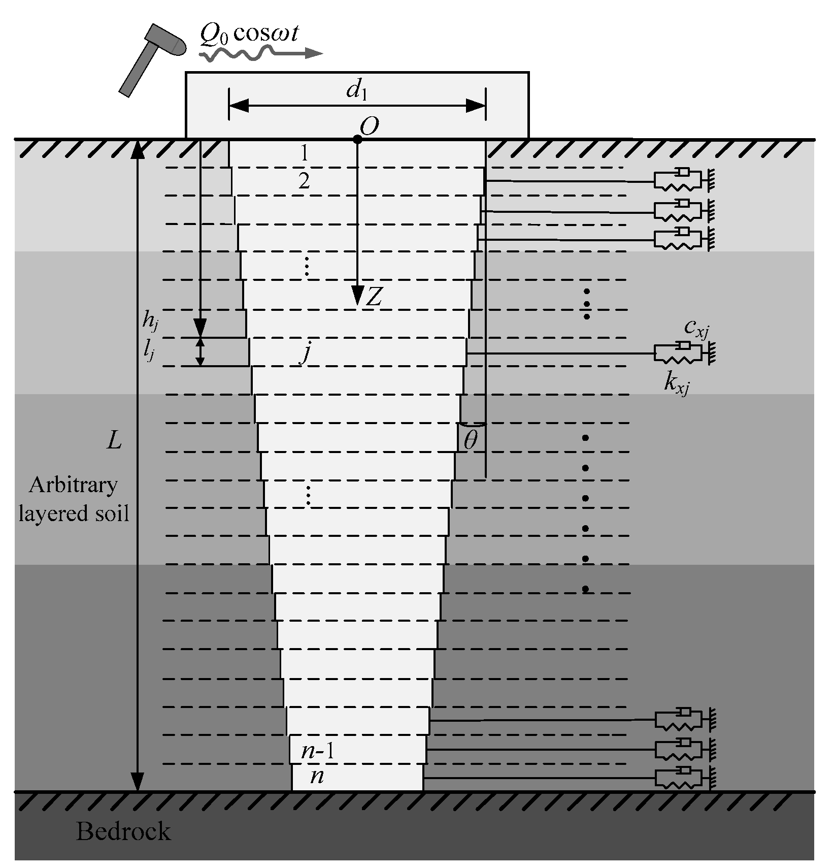
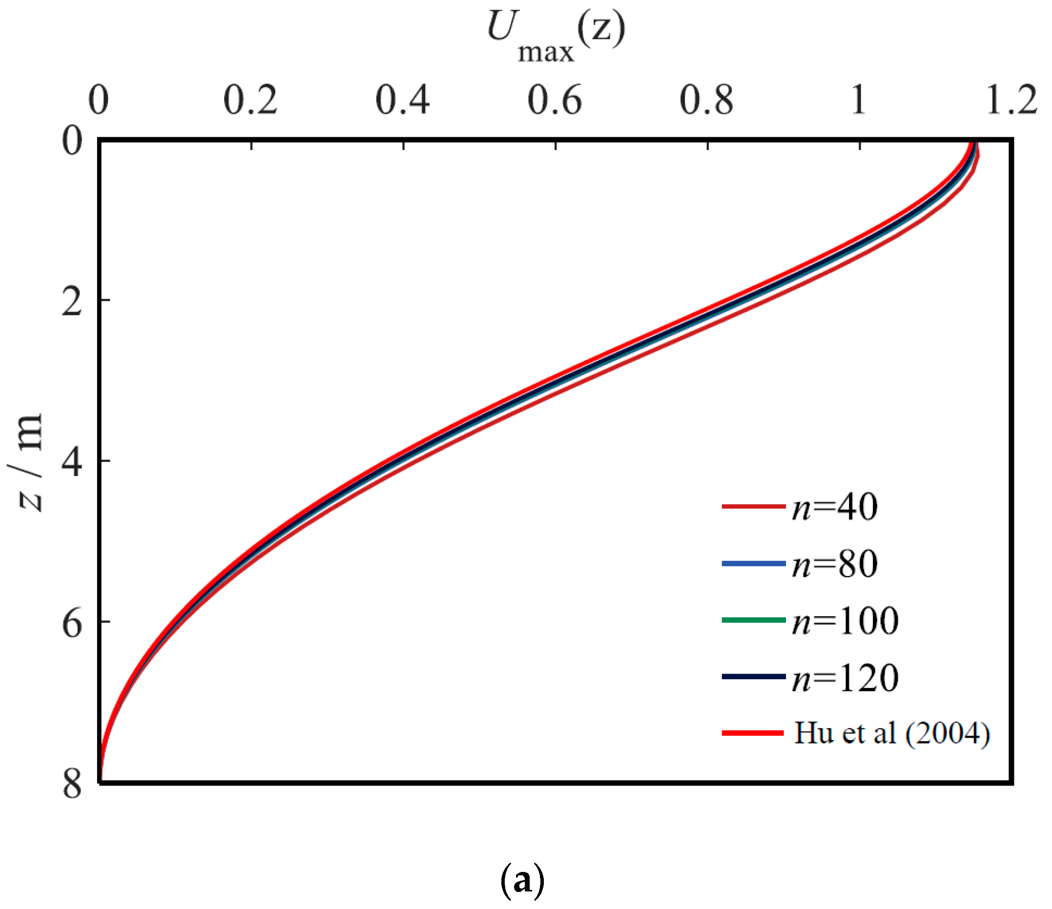
4. Rationality Analysis of the Present Solutions

This work theoretically studies the horizontal vibration of TP in arbitrarily layered soil based on some assumptions. Therefore, the rationality of the present solutions should be analyzed before parametric study. For convenience, the PSS is taken as two layers with the same density of 2000 kg/m3, a damping ratio of 0.05, and Poisson’s ratio of 0.4. The property difference of these two soil layers can be reflected by changing the shear modulus. The parameters of TP are set as: pile length of 8 m, pile head diameter of 0.6 m, cone angle of 0.8°, density of 2500 kg/m3, Poisson’s ratio of 0.17, and elastic modulus of 20 GPa. The other calculation parameters are set as: the amplitude of harmonic horizontal dynamic load Q 0 is 100 kN, the dimensionless frequency of pile head a 1 is 0.5, and the thickness of the upper soil layer is 1.6 m.
To analyze the rationality of the present solutions, the dimensionless forms of maximum HD, BM and SF of pile body are introduced as:
U j max ( z ) = E P 1 d 1 u j max / ( 500 Q 0 )
M j max ( z ) = m j max / ( 2 Q 0 d 1 )
Q j max ( z ) = q j max / Q 0
To verify the reliability of the proposed solutions, the cone angle is set to 0°, so that the present solutions of TP can be reduced to the solutions of a circular cross-section pile with equal diameter and can then be compared with the solutions of Hu et al. [32]. The elastic moduli of the two PSS layers are given as 4 MPa. The number of TP segments is set as 40, 80, 100 and 120, respectively. Figure 2 shows the comparisons of HD, BM and SF of pile body calculated by the degenerate solution and Hu’s solution [32], where the ordinate represents the soil depth. When the number of TP–soil segments n is greater than 80, the curves calculated by the two solutions tend to be stable and consistent. To ensure calculation accuracy, n is set to 100 in the following analyses, that is, the ratio of the thickness of the micro segment to the pile length is 1/100.
In the literature [14,18], it is found that the horizontal dynamic behaviors of long and thin piles gained by using the TS beam model and EB beam model are very close, but for TP, the difference between the two models is still unknown. Therefore, the difference between the TS beam model and EB beam model in analyzing the horizontal vibration characteristics of TP was studied to illustrate the rationality of the present solutions. Utilizing the same derivation process as this paper, the solutions of the horizontal vibration characteristics of TP based on the EB beam model were also obtained. However, due to content limitations, the derivation process based on the EB beam model was not given in this paper. For comparison, the length–diameter (diameter of pile head) ratio of the pile was set to 5, and the cone angles were set to 0°, 0.8° and 1.6°, respectively.
Figure 3 illustrates the comparison between the results obtained by the TS beam model and EB beam model. From Figure 3a, the HDs of TP obtained by both TS beam model and EB beam model decrease as the pile depth increases, and increase as the cone angle increases. The reason for this phenomenon is that, for the same diameter of pile head, the larger cone angle would lead to a smaller diameter of pile bottom, which results in an increase in HD of TP. The HD of TP obtained by the TS beam model is larger than that obtained by the EB beam model for the TS beam model and takes the shear deformation of TP into account. From Figure 3b, the change in the cone angle and calculation model has little effect on the BM of TP. From Figure 3c, the SFs of TP obtained by both the TS beam model and EB beam model decrease as the pile depth and cone angle increase. This is because, when the cone angle is smaller, the upper part of pile can bear more SF. In addition, the SF obtained by the TS beam model is smaller than that obtained by the EB beam model because the upper part of pile bears more SF when considering the shear deformation of TP. In general, since the TS beam model can consider the shear deformation of the TP, the deformation obtained by the TS beam model is relatively larger, which is conducive to the safe design of the pile foundation.

5. Parametric Study

In this section, the influences of soil and pile properties on the horizontal vibration characteristics of TPs are systemically researched. Unless otherwise specified, the parameters in this section are consistent with those in Section 4.

5.1. Influence of Shear Modulus of Soil

When analyzing the influence of the shear modulus of soil, there are two situations. The first situation is to keep the shear modulus of the lower soil unchanged at 4 MPa, and the shear moduli of upper soil are set as 2.4 MPa, 3.2 MPa, 4 MPa, 4.8 MPa and 5.6 MPa, respectively. The other situation is to keep the shear modulus of upper soil unchanged at 4 MPa, and the shear moduli of lower soil are set as 2.4 MPa, 3.2 MPa, 4 MPa, 4.8 MPa and 5.6 MPa, respectively.
Figure 4 depicts the HD curves of a pile body in the two situations. Whether the shear modulus of the upper soil or lower soil is changed, the HD of pile body decreases as the soil shear modulus increases. However, the influence of changing the shear modulus of upper soil on the HD of the TP is larger than that of lower soil because the upper soil directly bears a horizontal dynamic load transmitted from the TP. A further analysis of Figure 4 depicts that changing the shear modulus of the lower soil has a relatively uniform effect on the HD of the pile body above the pile bottom, while the HD of the pile bottom is always 0 because the pile bottom is fixed. The change in the shear modulus of the upper soil has little effect on the HD of the pile body at the position of 6~8 m. This is because the thickness of the upper soil is only 1.6 m, which makes it difficult to influence the horizontal vibration characteristics of the pile body near the bottom because its influence will be weakened by the increasing depth of the lower soil. In conclusion, the engineering properties of the upper soil are more important than those of the lower soil. From Figure 4a, when the shear moduli of the upper soil are 2.4 MPa and 5.6 MPa, the HD of pile top increases by 17.1% and decreases by 12.2%, respectively, compared with that of homogeneous foundation (i.e., ES1/ES2 = 1). This phenomenon indicates that the soft upper soil has a greater effect on the horizontal vibration characteristics of TP than that of the hard upper soil. Therefore, in practical engineering, the upper soil can be treated and strengthened to improve the stability of the TP foundation.

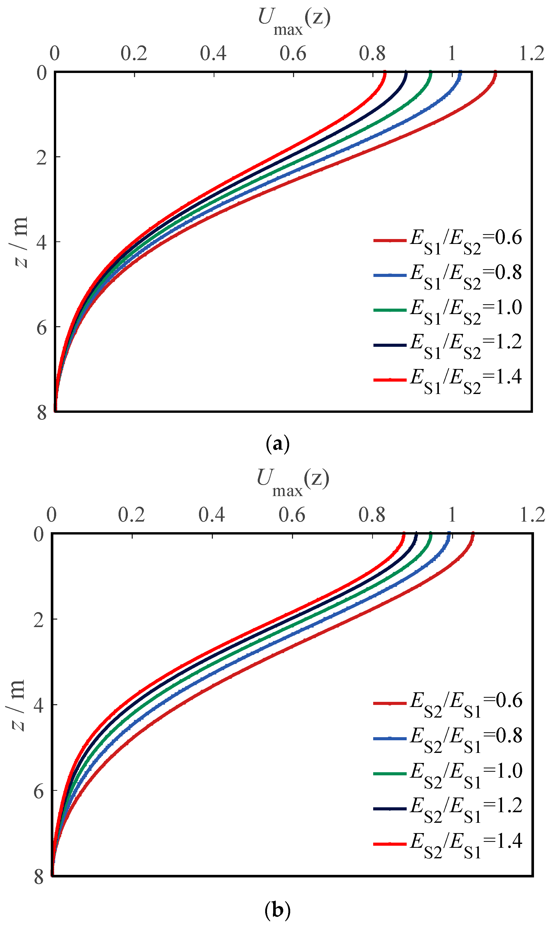
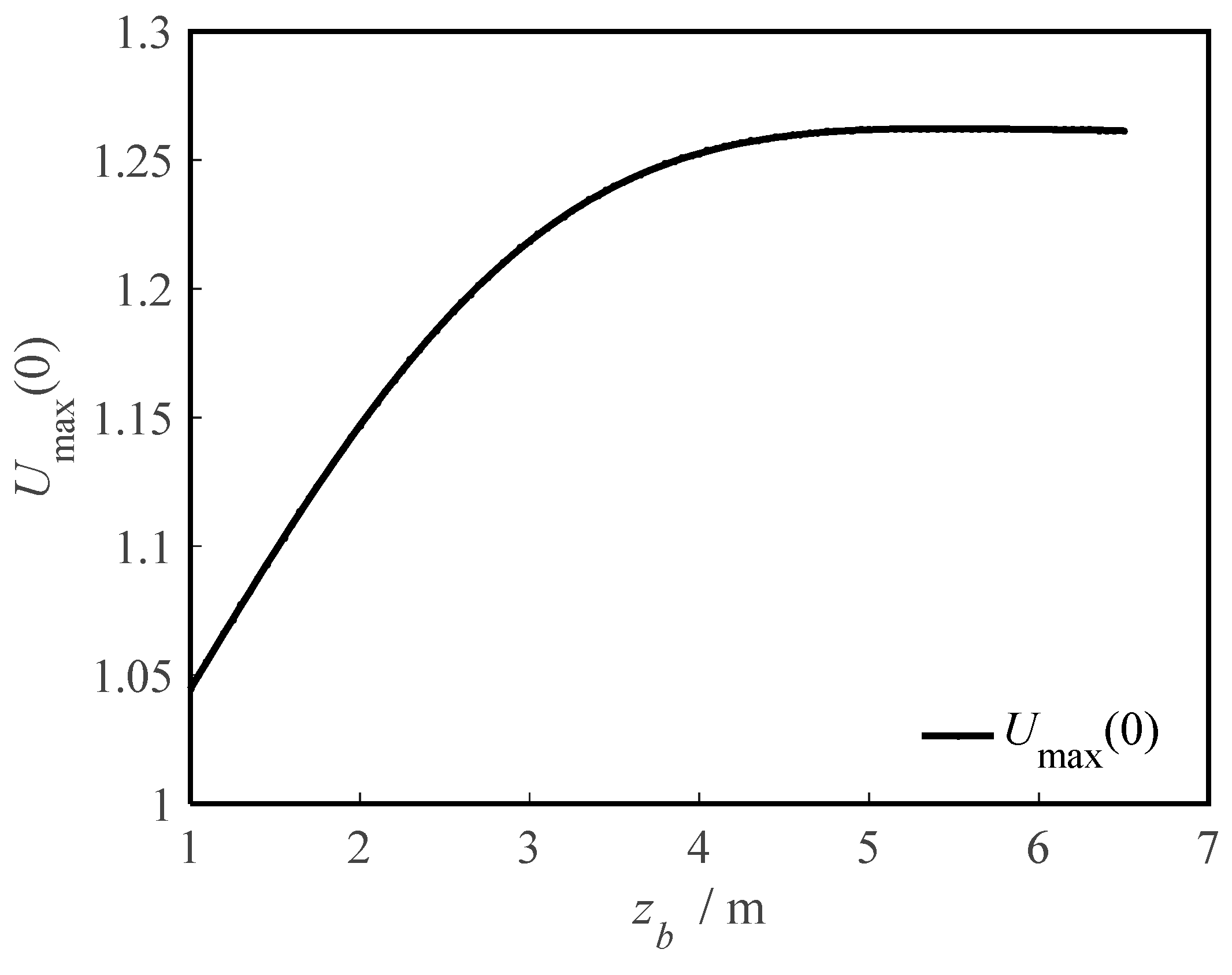
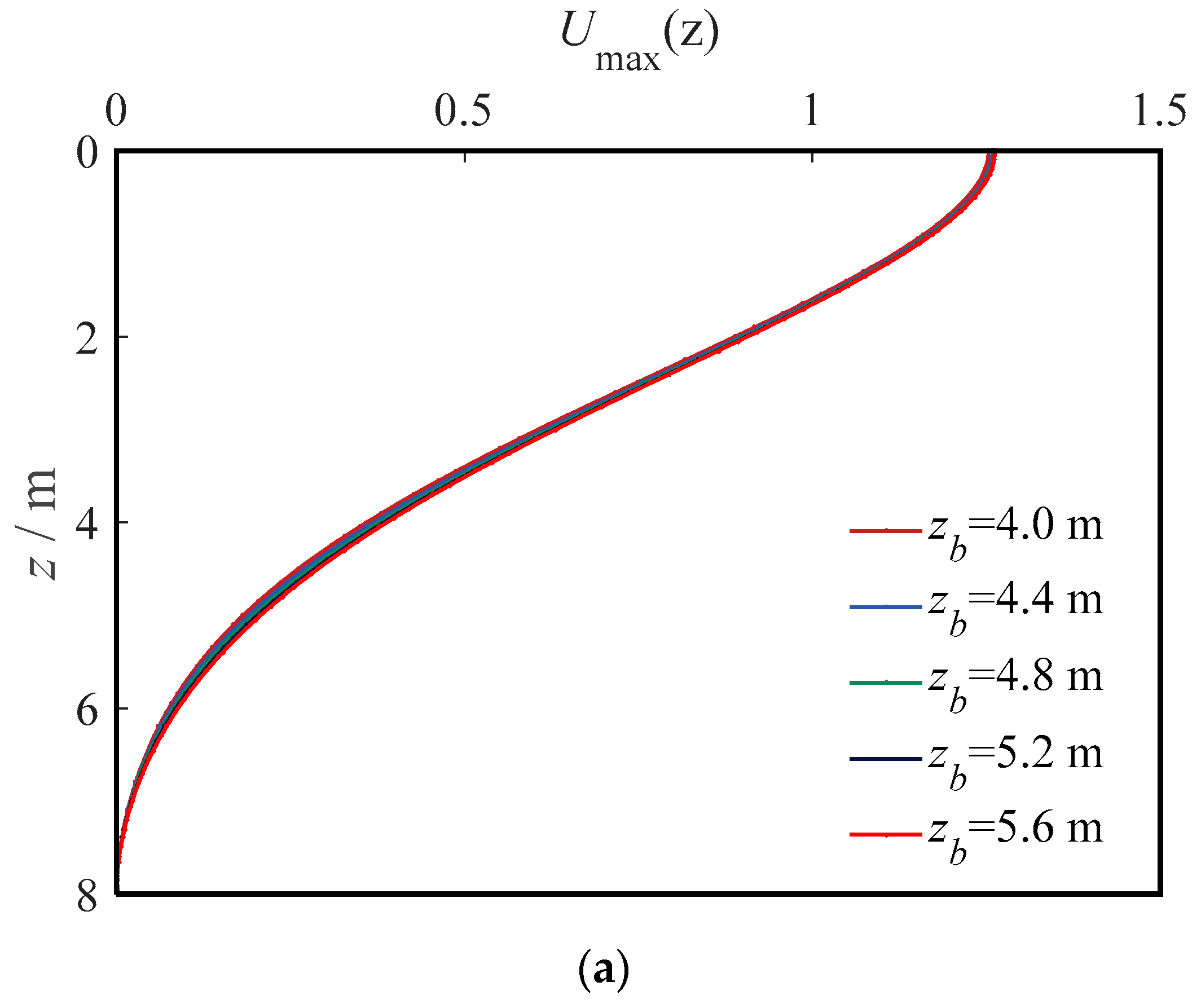
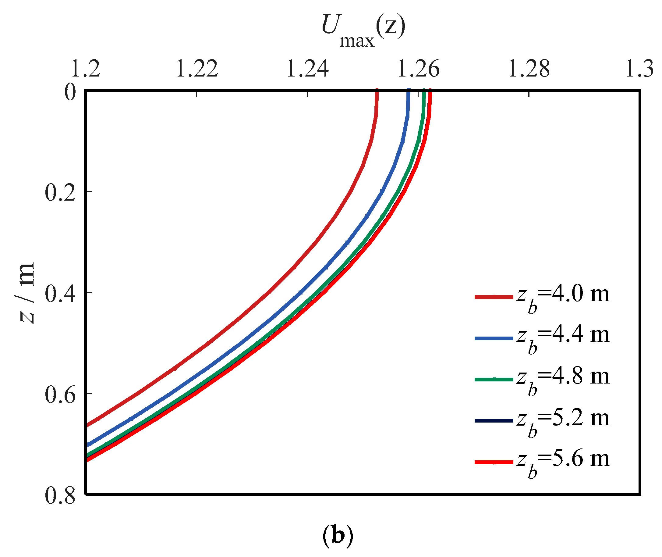
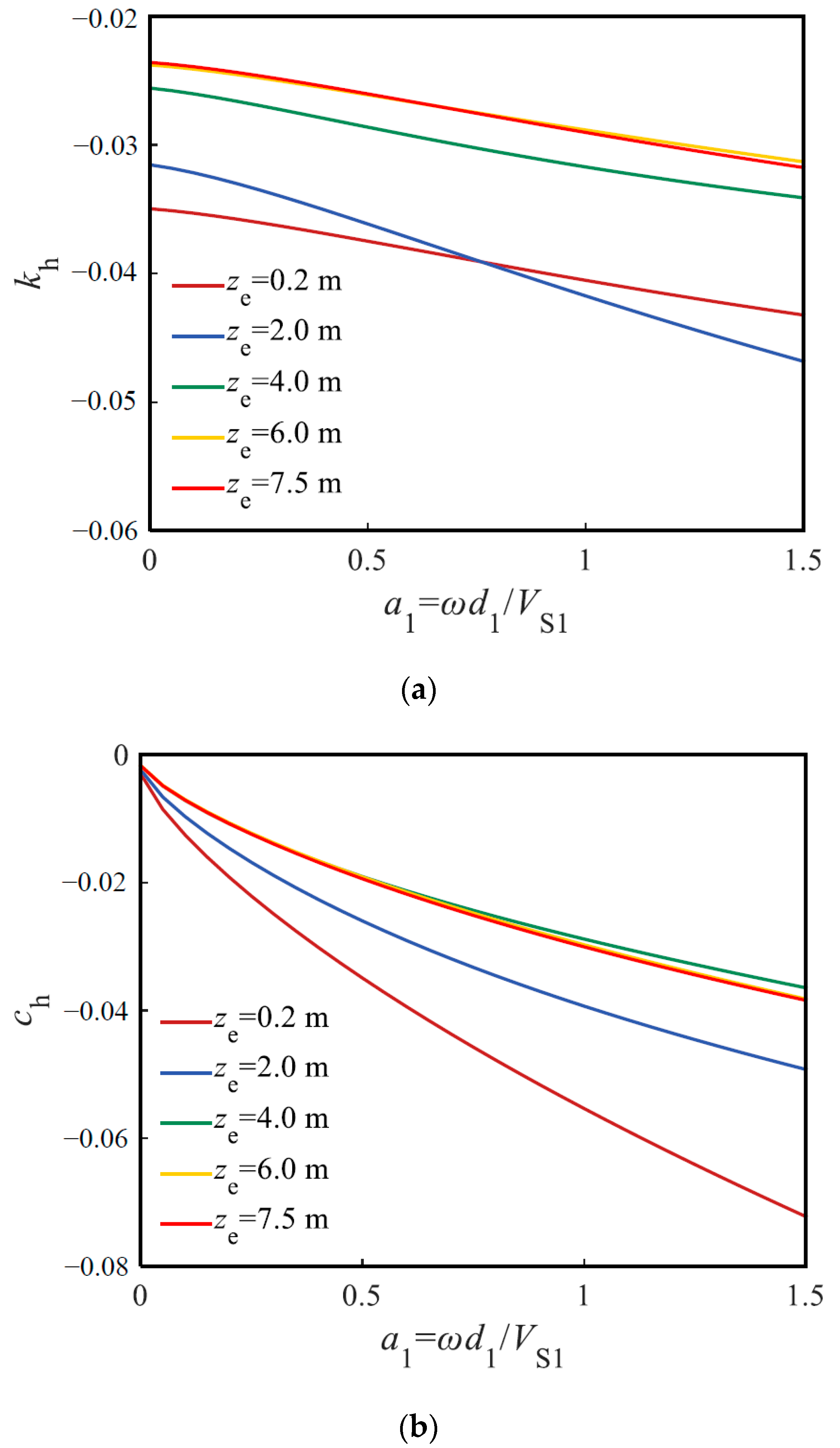
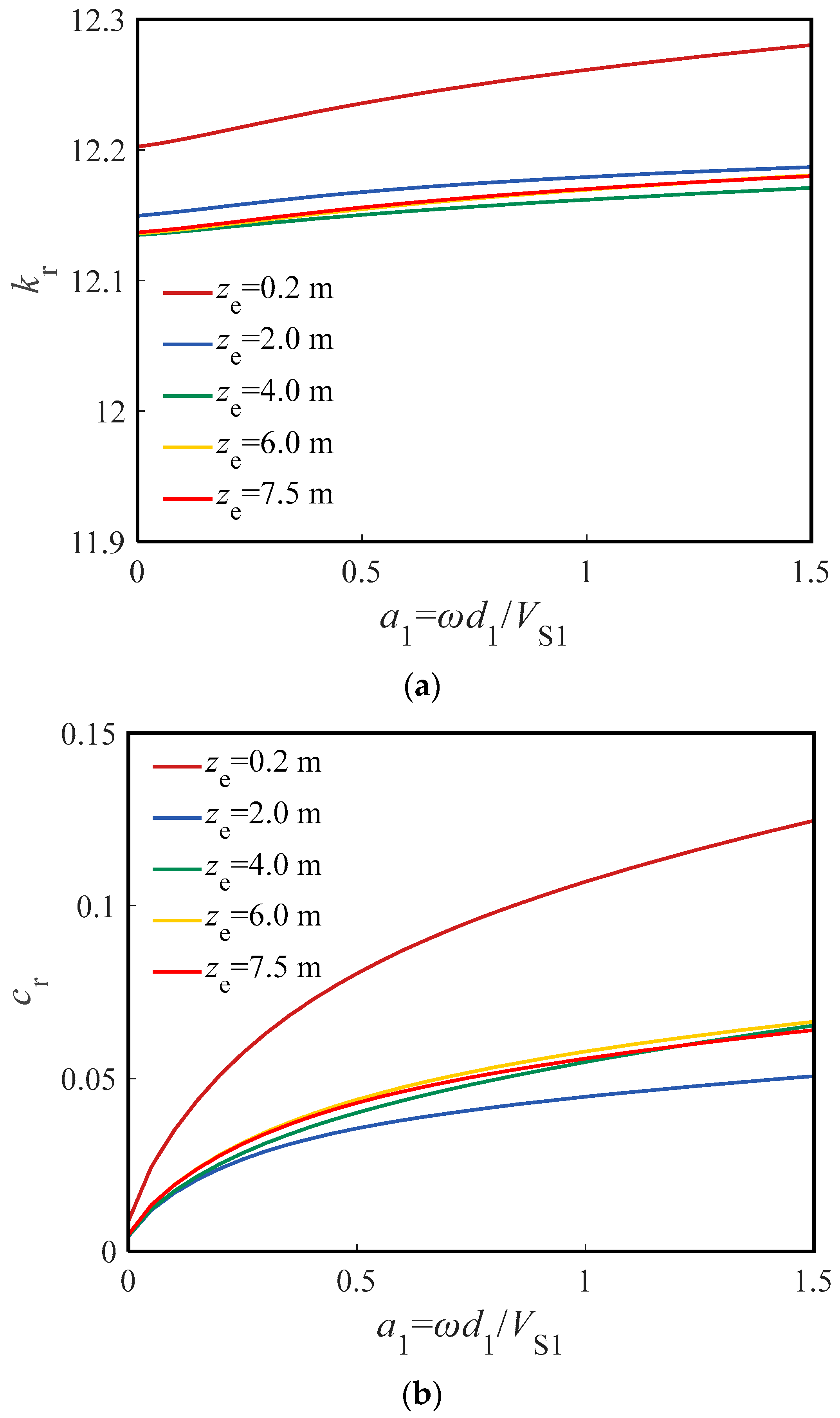
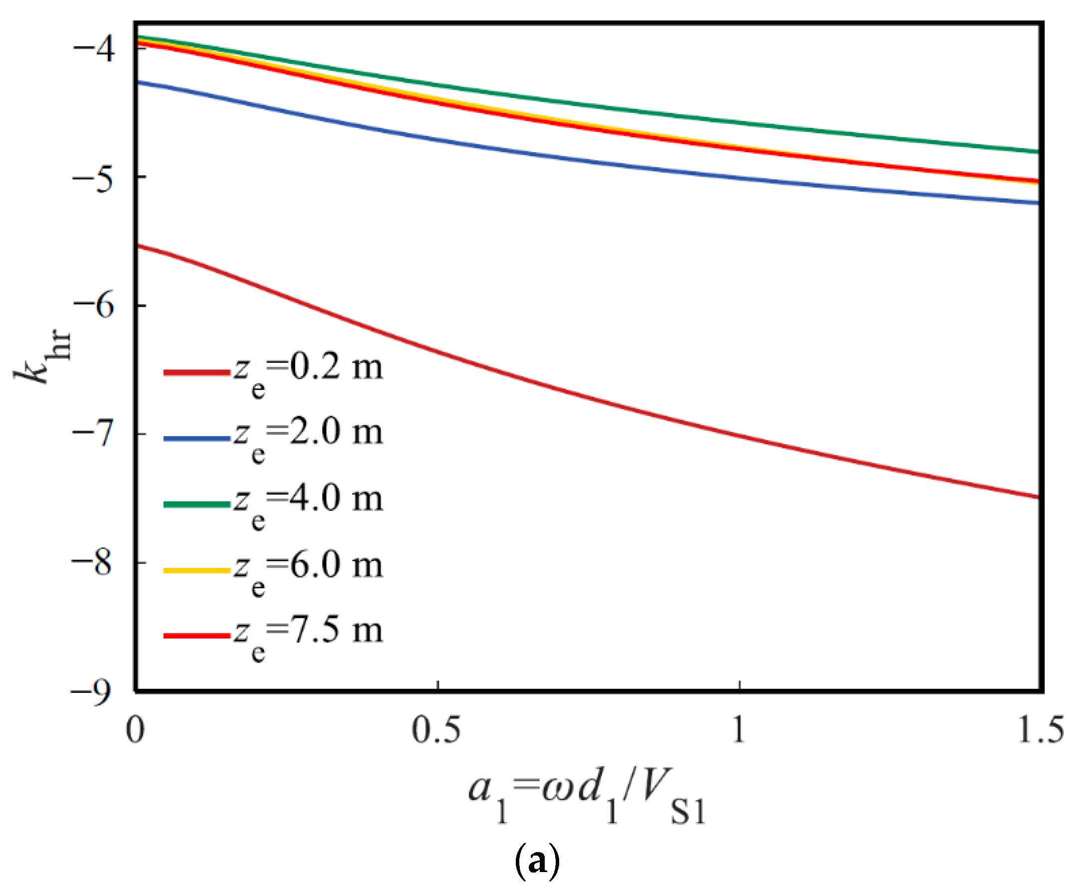
5.2. Influence of Upper Soil Thickness

According to the analysis in Section 5.1, when the soil is soft in the upper part and hard in the lower part, the upper soil has a great effect on the horizontal vibration characteristics of the TP, but there is a critical-influence thickness of the upper soil. If the upper soil thickness is greater than the critical-influence thickness, the degree of influence does not increase. Therefore, this section intends to obtain the critical-influence thickness using a parametric study. The shear modulus of the upper soil is 2.4 MPa, and the shear modulus of the lower soil is 4 MPa. The thickness of upper soil is denoted by zb.
Figure 5 illustrates the effect of the upper soil thickness on the HD of the pile head, where the abscissa is the upper soil thickness, and the ordinate is the HD of the pile head. The HD pile head increases as the upper soil thickness increases. However, if the upper soil thickness is larger than 5 m, the HD of the pile head reaches its maximum and remains effectively unchanged. Furthermore, the HD of pile body is calculated by setting the upper soil thickness as 4 m, 4.4 m, 4.8 m, 5.2 m and 5.6 m, respectively. As depicted in Figure 6, the two HD envelopes for the upper soil thicknesses of 5.2 m and 5.6 m completely coincide, which indicates that the upper soil thickness reaches its critical value. This phenomenon implies that, in the applications of soil improvement, if the upper soil thickness is higher than the critical-influence thickness, a further increase in the hard upper soil thickness will not further strengthen the ability of the TP–soil system to resist horizontal vibration.

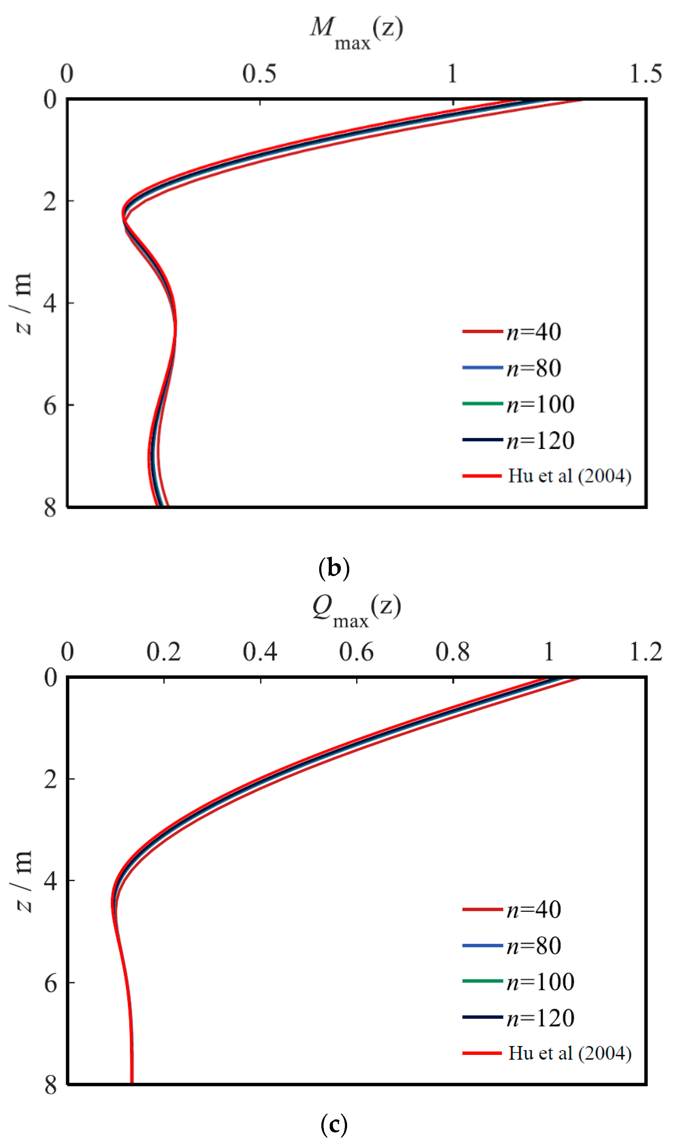
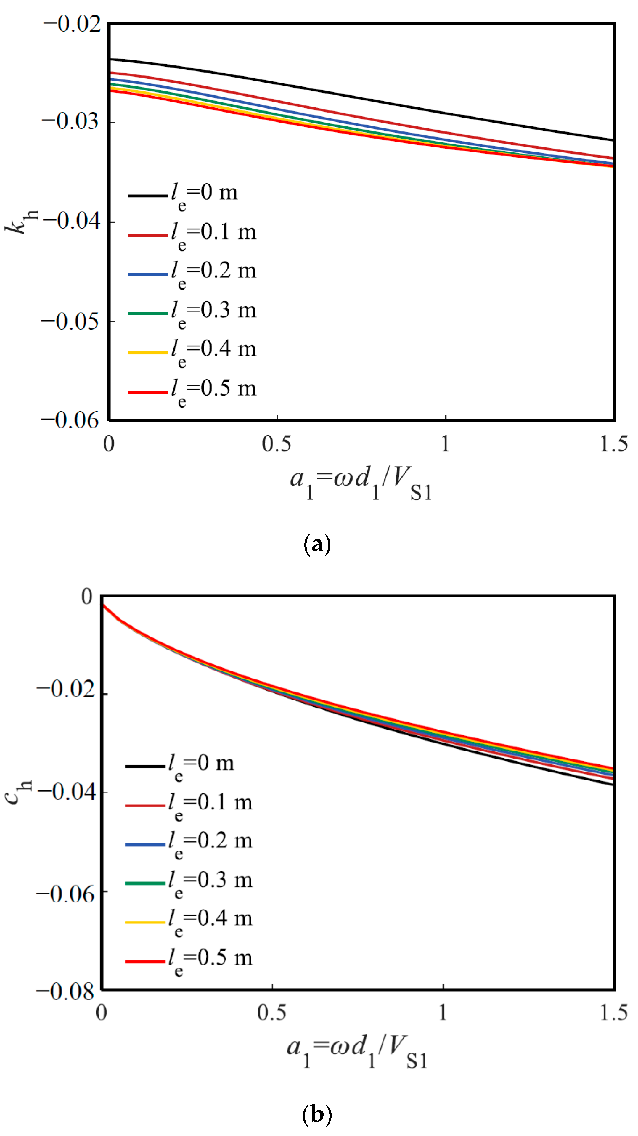
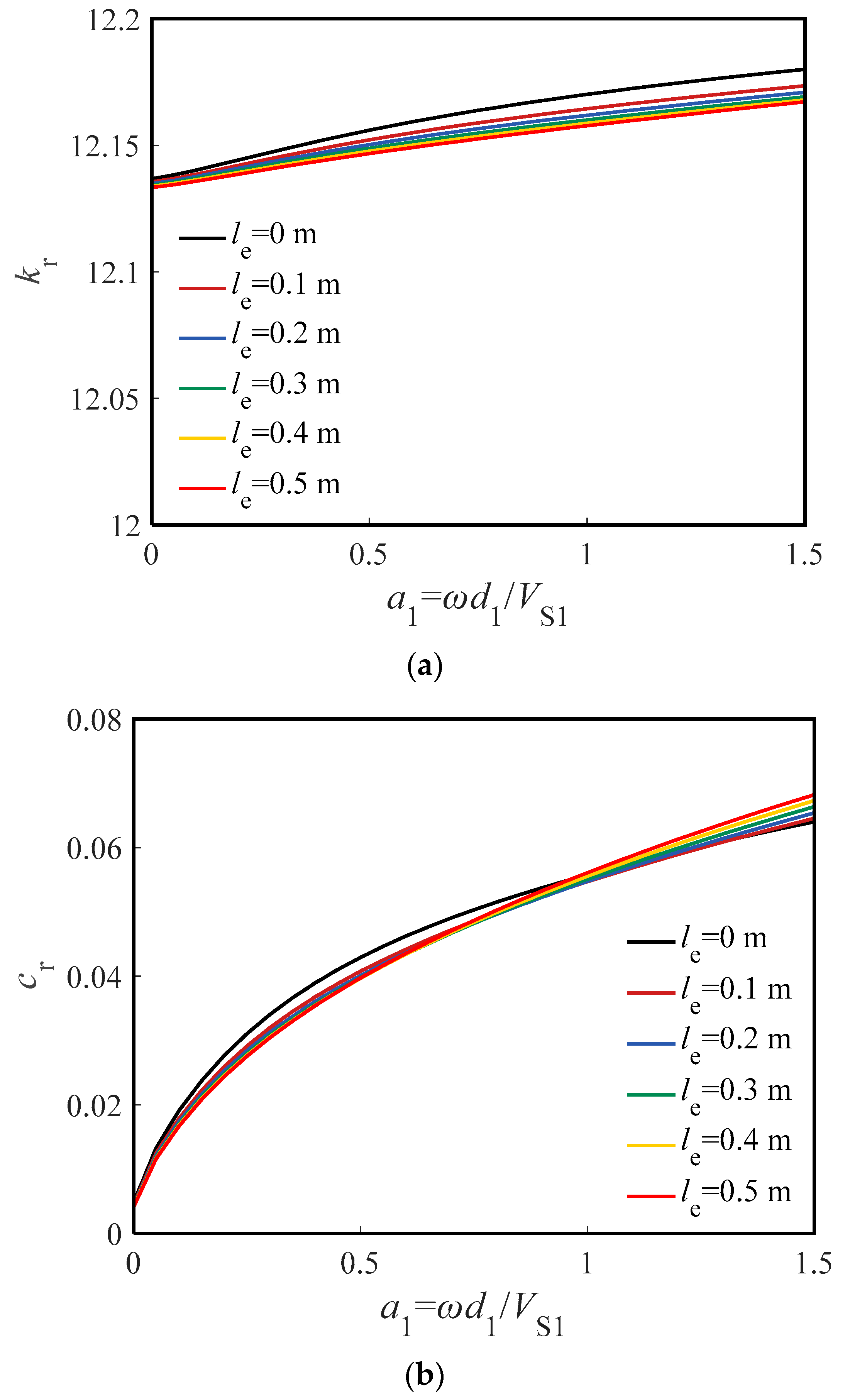
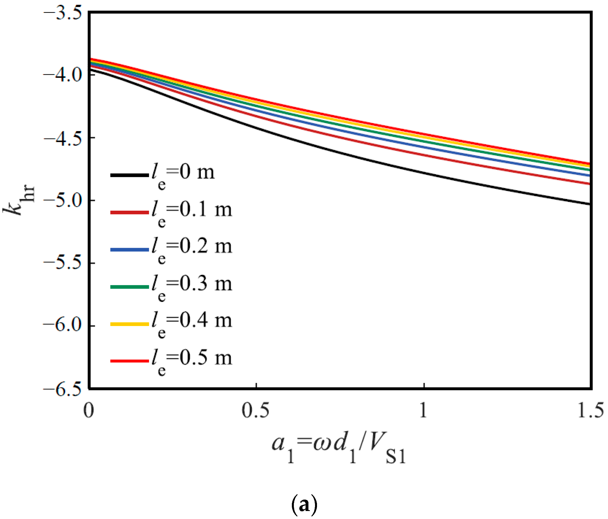
5.3. Influence of Weak Pile Segment Length

When pouring concrete in pile foundation engineering, the concrete is often segregated due to complex properties of soil layers, which lead to a weak pile segment in the pile body. The weak pile segment has a significant influence on its bearing capacity. Therefore, the influence of weak pile segment length is described in this section. The thickness of the upper soil is 5 m, shear modulus of upper soil is 2.4 MPa, and shear modulus of lower soil is 4 MPa; the shear modulus, mass density and Poisson’s ratio of the weak pile segment are 2 GPa, 2000 kg/m3 and 0.24, respectively. The top depth of the weak pile segment is set as 4 m (i.e., the middle part of the TP), and the weak pile segment length is denoted by le and set as 0.1 m, 0.2 m, 0.3 m, 0.4 m and 0.5 m in turn. The other parameters are the same as those in Section 4.
Figure 7, Figure 8 and Figure 9 illustrate the influence of the weak pile segment on the HDI, RDI and HRDI of the pile head, respectively. The influence of the weak pile segment length on the three kinds of dynamic impedances of the pile head in the low-frequency range is less than that in the high-frequency range, and its degree of influence gradually increases as the frequency increases. Compared with the damping factor of the pile head, the stiffness factor of the pile head is more influenced by the weak pile segment length. When the concrete of pile body is segregated, the absolute values of the three kinds of dynamic impedances of pile head gradually decrease, and its reduction rate is negatively correlated with weak pile segment length. Additionally, if the weak pile segment length is greater than 0.4 m, the three kinds of dynamic impedances of the pile head are essentially unaffected by the weak pile segment length.

5.4. Influence of the Weak Pile Segment Position

To investigate the influence of the weak pile segment position on the horizontal vibration characteristics of the TP, the weak pile segment length is set as 0.2 m and, in turn, can be set at the top, upper part, middle part, lower part and bottom of the TP. In other words, the depths of the top surface of the weak pile segment are set as 0.2 m, 2 m, 4 m, 6 m and 7.5 m, respectively.
Figure 10, Figure 11 and Figure 12 depict the influence of the weak pile segment position on the HDI, RDI and HRDI of the pile head, respectively. The closer the weak pile segment position to the pile head, the greater the absolute values of the three kinds of dynamic impedances of the pile head. When the weak pile segment depth increases, the absolute values of the three kinds of dynamic impedances decrease, and its reduction rate decreases with the increase in the depth of the weak pile segment. When the depth of weak pile segment is greater than 6 m, the three kinds of dynamic impedances of the pile head are essentially unaffected by the depth of the weak pile segment. This phenomenon indicates that, when the weak pile segment occurs at the lower part or the bottom of TP, its influence on the HDI of TP is smaller than that at other parts. Furthermore, in the whole frequency range, the weak pile segment position has relatively little influence on the three kinds of stiffness factors of pile head, but the three kinds of damping factors are greatly affected by the weak pile segment position in the high-frequency range. This phenomenon indicates that a high-frequency load will greatly harm the TP with the weak pile segment near the pile head and could lead to serious malfunctions in engineering quality. Therefore, attention should be paid to prevent the occurrence of a weak pile segment near the pile head in practical engineering.

6. Conclusions

To investigate the horizontal vibration problems of a TP, this paper first proposes the analytical solutions for the HD, BM and SF of a TP undergoing a horizontally dynamic load. Then, the analytical solutions for the HDI, RDI and HRDI of the TP are also derived. Based on the present solutions, a parametric study is carried out to study the effect of soil and pile properties on the horizontal vibration characteristics of TPs. The main conclusions are summarized as follows:
(1)
In practical engineering, the ability of the TP–soil system to resist horizontal vibrations can be improved by strengthening the upper soil. There is a critical-influence thickness for the influence of upper soil thickness on the horizontal vibration characteristics of TP. If the reinforcement depth exceeds the critical-influence thickness, increasing the reinforcement depth will not further enhance the ability of the TP–soil system to resist horizontal vibration.
(2)
The effect of the weak pile segment length on the horizontal vibration characteristics of the TP in the low-frequency range is less than that in the high-frequency range. Compared with the damping factor of dynamic impedance of the TP, the stiffness is more affected by the weak pile segment length.
(3)
A closer position of the weak pile segment to the pile head can lead to greater absolute values for the three kinds of dynamic impedances of the pile head. When the depth of weak pile segment increases, the absolute values of the three kinds of dynamic impedance of the pile head decrease, and its reduction rate decreases with the increase in depth.
One limitation of this paper is that the interaction between the pile cap and soil is ignored, which may lead to a difference between the theoretical results of TP and its actual engineering characteristics. In the follow-up research, this team of authors will consider the influence of the dynamic interactions between pile cap and soil on the horizontal vibration characteristics of TP.

Author Contributions

X.Y.: analytical analysis, writing—original draft. G.J.: project administration, formal analysis. H.L.: analytical analysis, writing—review and editing. W.W.: project administration, funding acquisition, conceptualization. G.M.: formal analysis, review and editing. Z.Y.: Analytical analysis, writing—original draft. All authors have read and agreed to the published version of the manuscript.

Funding

This research is supported by the Outstanding Youth Project of Natural Science Foundation of Zhejiang Province (Grant No. LR21E080005), and the National Natural Science Foundation of China (Grant Nos. 52178371, 51878634, 52108347, 52108355, 52178321), and the Exploring Youth Project of Zhejiang Natural Science Foundation (Grant No. LQ22E080010).

Institutional Review Board Statement

Not applicable.

Informed Consent Statement

Not applicable.

Data Availability Statement

All the data used in this research can be easily accessible by downloading the various documents appropriately cited in the paper.

Conflicts of Interest

The authors declare no conflict of interest.

References

  1. El Naggar, M.H.; Wei, J.Q. Response of tapered piles subjected to lateral loading. Can. Geotech. J. 1999, 36, 52–71. [Google Scholar] [CrossRef]
  2. El Naggar, M.H.; Wei, J.Q. Axial capacity of tapered piles established from model tests. Can. Geotech. J. 1999, 36, 1185–1194. [Google Scholar] [CrossRef]
  3. Ghazavi, M.; Ahmadi, H.A. Long-term capacity of driven non-uniform piles in cohesive soil–field load tests. In Proceedings of the 8th International Conference on the Application of Stress Wave Theory to Piles, Lisbon, Portugal, 9 July–9 December 2008; pp. 132–139. [Google Scholar]
  4. Zil’berberg, S.D.; Sherstnev, A.D. Construction of compaction tapered pile foundations. Soil Mech. Found. Eng. 1990, 27, 96–101. [Google Scholar] [CrossRef]
  5. Wang, L.X.; Wu, W.B.; Zhang, Y.P.; Li, L.C.; Liu, H.; El Naggar, M.H. Nonlinear analysis of single pile settlement based on stress bubble fictitious soil pile model. Int. J. Numer. Anal. Meth. 2022. [Google Scholar] [CrossRef]
  6. El Naggar, M.H.; Mohammed, S. Evaluation of axial performance of tapered piles from centrifuge tests. Can. Geotech. J. 2000, 37, 1295–1308. [Google Scholar] [CrossRef]
  7. Li, L.C.; Liu, H.; Wu, W.B.; Wen, M.J.; El Naggar, M.H.; Yang, Y.Z. Investigation on the behavior of hybrid pile foundation and its surrounding soil during cyclic lateral loading. Ocean Eng. 2021, 240, 110006. [Google Scholar] [CrossRef]
  8. Li, L.C.; Zheng, M.Y.; Liu, X.; Wu, W.B.; Liu, H.; El Naggar, M.H.; Jiang, G.S. Numerical analysis of the cyclic loading behavior of monopile and hybrid pile foundation. Comput. Geotech. 2022, 144, 104635. [Google Scholar] [CrossRef]
  9. Saha, S.; Ghosh, D. Vertical vibration of tapered piles. J. Geotech. Eng. 1986, 112, 290–302. [Google Scholar] [CrossRef]
  10. Xie, J.; Vaziri, H.H. Vertical vibration of nonuniform piles. J. Eng. Mech. 1991, 117, 1105–1118. [Google Scholar] [CrossRef]
  11. Ghazavi, M. Response of tapered piles to axial harmonic loading. Can. Geotech. J. 2008, 45, 1622–1628. [Google Scholar] [CrossRef]
  12. Wu, W.B.; Jiang, G.S.; Dou, B.; Leo, C.J. Vertical dynamic impedance of tapered pile considering compacting effect. Math. Probl. Eng. 2013, 2013, 304856. [Google Scholar] [CrossRef] [Green Version]
  13. El Naggar, M.H. Vertical and torsional soil reactions for radially inhomogeneous soil layer. Struct. Eng. Mech. 2000, 10, 299–312. [Google Scholar] [CrossRef]
  14. Wu, W.B.; Yang, Z.J.; Liu, X.; Zhang, Y.P.; Liu, H.; El Naggar, M.H.; Xu, M.J.; Mei, G.X. Horizontal dynamic response of pile in unsaturated soil considering its construction disturbance effect. Ocean Eng. 2022, 245, 110483. [Google Scholar] [CrossRef]
  15. Zhang, Y.P.; Jiang, G.S.; Wu, W.B.; El Naggar, M.H.; Liu, H.; Wen, M.J.; Wang, K.H. Analytical solution for distributed torsional low strain integrity test for pipe pile. Int. J. Numer. Anal. Meth. 2022, 46, 47–67. [Google Scholar] [CrossRef]
  16. Zhang, Y.P.; Liu, H.; Wu, W.B.; Wang, S.; Wu, T.; Wen, M.J.; Jiang, G.S.; Mei, G.X. Interaction model for torsional dynamic response of thin-wall pipe piles embedded in both vertically and radially inhomogeneous soil. Int. J. Geomech. 2021, 21, 04021185. [Google Scholar] [CrossRef]
  17. Wu, W.B.; Liu, H.; Yang, X.Y.; Jiang, G.S.; El Naggar, M.H.; Mei, G.X.; Liang, R.Z. New method to calculate apparent phase velocity of open-ended pipe pile. Can. Geotech. J. 2020, 57, 127–138. [Google Scholar] [CrossRef]
  18. Huang, Y.M.; Wang, P.G.; Zhao, M.; Zhang, C.; Du, X.L. Dynamic responses of an end-bearing pile subjected to horizontal earthquakes considering water-pile-soil interactions. Ocean Eng. 2021, 238, 109726. [Google Scholar] [CrossRef]
  19. Huang, K.; Sun, Y.W.; Zhou, D.Q.; Li, Y.J.; Jiang, M.; Huang, X.Q. Influence of water-rich tunnel by shield tunneling on existing bridge pile foundation in layered soils. J. Cent. South Univ. 2021, 28, 2574–2588. [Google Scholar] [CrossRef]
  20. Wang, J.; Zhou, D.; Zhang, Y.Q.; Cai, W. Vertical impedance of a tapered pile in inhomogeneous saturated soil described by fractional viscoelastic model. Appl. Math. Model 2019, 75, 88–100. [Google Scholar] [CrossRef]
  21. Bryden, C.; Arjomandi, K.; Valsangkar, A. Dynamic axial stiffness and damping parameters of tapered piles. Int. J. Geomech. 2018, 18, 06018014. [Google Scholar] [CrossRef]
  22. Bryden, C.; Arjomandi, K.; Valsangkar, A. Dynamic axial response of tapered piles including material damping. Pract. Period. Struct. 2020, 25, 04020001. [Google Scholar] [CrossRef]
  23. Wu, W.B.; Jiang, G.S.; Lü, S.H.; Huang, S.G.; Xie, B.H. Torsional dynamic impedance of a tapered pile considering its construction disturbance effect. Mar. Georesour. Geotec. 2016, 34, 321–330. [Google Scholar] [CrossRef]
  24. Guan, W.J.; Wu, W.B.; Jiang, G.S.; Leo, C.J.; Deng, G.D. Torsional dynamic response of tapered pile considering compaction effect and stress diffusion effect. J. Cent. South Univ. 2020, 27, 3839–3851. [Google Scholar] [CrossRef]
  25. Ghazavi, M. Analysis of kinematic seismic response of tapered piles. Geotech. Geol. Eng. 2007, 25, 37–44. [Google Scholar] [CrossRef]
  26. Lee, J.K.; Park, S.H.; Kim, Y. Transverse free vibration of axially loaded tapered friction piles in heterogeneous soil. Soil Dyn. Earthq. Eng. 2019, 117, 116–121. [Google Scholar] [CrossRef]
  27. Gupta, B.K.; Basu, D. Applicability of Timoshenko, Euler–Bernoulli and rigid beam theories in analysis of laterally loaded monopiles and piles. Géotechnique 2018, 68, 772–785. [Google Scholar] [CrossRef]
  28. Gupta, B.K.; Basu, D. Timoshenko beam theory–based dynamic analysis of laterally loaded piles in multilayered viscoelastic soil. J. Eng. Mech. 2018, 144, 04018091. [Google Scholar] [CrossRef]
  29. Ding, X.M.; Luan, L.B.; Zheng, C.J.; Zhou, W. Influence of the second-order effect of axial load on lateral dynamic response of a pipe pile in saturated soil layer. Soil Dyn. Earthq. Eng. 2017, 103, 86–94. [Google Scholar] [CrossRef]
  30. Zheng, C.J.; Luan, L.B.; Qin, H.Y.; Zhou, H. Horizontal dynamic response of a combined loaded large-diameter pipe pile simulated by the Timoshenko bean theory. Int. J. Struct. Stab. Dyn. 2019, 20, 2071003. [Google Scholar] [CrossRef]
  31. Gazetas, G.; Dobyr, R. Horizontal response of piles in layered soils. J. Geotech. Eng. 1984, 110, 20–40. [Google Scholar] [CrossRef]
  32. Hu, A.F.; Xie, K.H.; Ying, H.W.; Qian, L. Analytical theory of lateral vibration of single pile in visco-elastic subgrade considering shear deformation. Chin. J. Rock. Mech. Eng. 2004, 23, 1515–1520. (In Chinese) [Google Scholar]
Figure 1. Transverse coupling vibration model of TP.
Energies 15 03193 g001
Figure 2. Comparison of the present solutions with the solution of Hu et al. [32]. (a) Horizontal displacement envelope, (b) bending moment envelope, (c) shear force envelope.
Energies 15 03193 g002aEnergies 15 03193 g002b
Figure 3. Comparison between the results obtained by TS beam model and EB beam model. (a) Horizontal displacement envelope, (b) bending moment envelope, (c) shear force envelope.
Energies 15 03193 g003aEnergies 15 03193 g003b
Figure 4. Influence of shear modulus of soil on the horizontal displacement of TP. (a) Variable shear modulus of upper soil and (b) variable shear modulus of lower soil.
Energies 15 03193 g004
Figure 5. Influence of upper soil thickness on the horizontal displacement of pile head.
Energies 15 03193 g005
Figure 6. Influence of upper soil thickness on the horizontal displacement of pile body. (a) Horizontal displacement of TP (depth 0~8 m) and (b) horizontal displacement of TP (depth 0~0.8 m).
Energies 15 03193 g006aEnergies 15 03193 g006b
Figure 7. Influence of weak pile segment length on the HDI of pile head. (a) Stiffness factor of HDI and (b) damping factor of HDI.
Energies 15 03193 g007
Figure 8. Influence of weak pile segment length on the RDI of pile head. (a) Stiffness factor of RDI and (b) damping factor of RDI.
Energies 15 03193 g008
Figure 9. Influence of weak pile segment length on the HRDI of pile head. (a) Stiffness factor of HRDI and (b) damping factor of HRDI.
Energies 15 03193 g009aEnergies 15 03193 g009b
Figure 10. Influence of weak pile segment position on the HDI of pile head. (a) Stiffness factor of HDI and (b) damping factor of HDI.
Energies 15 03193 g010
Figure 11. Influence of weak pile segment position on the RDI of pile head. (a) Stiffness factor of RDI and (b) damping factor of RDI.
Energies 15 03193 g011
Figure 12. Influence of weak pile segment position on the HRDI of pile head. (a) Stiffness factor of HRDI and (b) damping factor of HRDI.
Energies 15 03193 g012aEnergies 15 03193 g012b
Publisher’s Note: MDPI stays neutral with regard to jurisdictional claims in published maps and institutional affiliations.

