Article

Distributed Secondary Control in Microgrids Using Synchronous Condenser for Voltage and Frequency Support

1
Department of Electrical and Computer Engineering, Florida International University, Miami, FL 33174, USA
2
Department of Electrical Engineering, The University of Danang-University of Science and Technology, Danang 550000, Vietnam
3
Department of Electrical and Computer Engineering, University of Connecticut, Storrs, CT 06268, USA
4
Department of Electrical and Electronic Engineering, Imperial College London, London SW7 2AZ, UK
5
Department of Civil and Environmental Engineering, University of Connecticut, Storrs, CT 06268, USA
*
Authors to whom correspondence should be addressed.
These authors contributed equally to this work.
Energies 2022, 15(8), 2968; https://doi.org/10.3390/en15082968
Submission received: 13 March 2022 / Revised: 8 April 2022 / Accepted: 14 April 2022 / Published: 18 April 2022

Abstract

:
A high share of distributed energy resources (DERs) in power distribution grids has posed many challenges for system operation and control. Microgrid (MG) application with different distributed control approaches for DERs has been drawn a lot of attention from the research community to provide more flexibility, reliability and resilience for the system. This paper develops a distributed secondary control for DERs in MGs and on top of that using synchronous condenser (SC) participating in the secondary control for voltage support. The proposed distributed secondary control framework of MGs is designed to obtain four objectives as follows: (i) frequency restoration, (ii) average voltage restoration, (iii) arbitrary active power sharing among SGs and BESSs and (iv) arbitrary reactive power sharing among all SGs, BESSs and SCs. The comparison results under different scenarios show that with SC participating in the distributed secondary control in MGs, the system frequency and voltage response are much improved and quickly recovered to the nominal values thanks to the natural inertia response and fast reactive power control of SC sharing with other DERs in the MGs. Additionally, a multi-agent system is implemented to realize the proposed control method in hardware environment.

1. Introduction

The integration of deep distributed energy resources (DERs) has been changing the characteristics of the power distribution system in terms of operation and control principles. This integration causes generation resources in distribution systems to be dispersed, intermittent and diverse. The applications of microgrids (MGs) become more common to provide flexibility, reliability and resiliency, but at the same time adds complexity to the active distribution networks. A microgrid can be on and off from the grid to enable it to operate in either grid-connected or islanded mode. This increases reliability, minimizes the impact of power disturbances to local utility, moderates ever-growing demand and curbs greenhouse gas emissions. However, the coordination of different DERs in MGs for frequency and voltage control is challenging for control, especially when it operates in an islanded mode with a small inertia constant.
MGs are normally operating under their local controller, which communicates with the control center in order to respond to different types of control signals. Moreover, MGs also have a metering infrastructure to collect local data to monitor their operation. Normally, the MG controller is based on centralized control where all components in MG communicate with the center by sending and receiving signals. With the increase of DERs in the MGs, the centralize control architecture will be more complicated and vulnerable. The distributed control strategy is a promising alternative approach to replace centralized control with MGCC to avoid single-point failure and communication burden.
Synchronous condensers (SCs) have started to receive attention from the research community for inertial support and system stability enhancement in low-inertia systems. SC is considered to play an important role in the system frequency stability and short-circuit level improvement for renewable-based systems [1,2]. In [3], SCs were deployed to enhance weak grids in rural areas thanks to the natural inertia response for frequency stability, fault level contribution and voltage regulation, which are challenging to achieve with power electronic systems on their own. SCs can be applied for both transmission and distribution systems: for transmission system, SCs can mitigate protection performance and coordination complication by providing short circuit level (SCL), phase-locked loop instability of inverter-based generation, quick changes in power flow, system instability and power system asynchronization due to different inertia constants. Additionally, SC can also provide power damping to improve low-frequency oscillation in low inertia systems through excitation system control [4]. They can also mitigate transient faults when integrating large-scale renewable energy resources. In distribution systems, SCs can alleviate large differences in SCL between day and night time, improve voltage dips caused by reduced SCL, as well as enhance power quality. They can be configured to provide different fault current during peak and off-peak load periods. SCs can support fault current and inertia response in the islanded mode of microgrids. SCs have been commissioned for grid-supporting applications all over the world, for instance: in August 2020, two ABB SCs were commissioned for the 685,000 MWh Darlington Point solar farm in New South Wales for stabilizing the local power grid with a high penetration of renewable energy; in February 2021, two SCs were installed for the Lister Drive Greener Grid project in Liverpool, England to strengthen the local grid and further integrate wind and solar power. However, the majority of SC applications are in transmission systems, where it is connected to the terminal to boost the voltage and short circuit level for the connections such as wind farm or long tie lines for inter-area connection [5,6,7].
The normal control structure for MGs is divided into three hierarchical layers: primary, secondary and tertiary. The primary control layer is usually based on a droop control scheme, while the secondary control aims to bring voltage and frequency back to their nominal values after the response of the primary one, and in the tertiary layer, normally, the energy management system is implemented to achieve an optimal operation and congestion management in the MG. To implement each control layer, three different approaches can be applied, which are based on centralized, decentralized and distributed methodologies [8]. The centralize control requires the center controller communicates with all components in the system and needs a huge capacity to process the information transmitted from all controllable elements in the system. This approach is not that robust, as they can cause single point failure. Meanwhile, with decentralized control, the control effort of each component is implemented using only local measurements. In distributed control, the control system is distributed along with the entire system, where all components operate in a coordinated way to achieve the global objectives [9,10,11,12,13,14,15]. In [9], a distributed secondary control was proposed for MGs using a multi-agent system architecture where frequency/voltage restoration and power-sharing objectives were achieved with control hardware in the loop validation of the stability considering network latency. Meanwhile, in [10], a cyber-physical design and implementation for distributed event-triggered secondary control was proposed for islanded MGs, which focuses more on communication networks of cyber system implementation and hardware in the loop validation. References [11,12,13] proposed a distributed secondary control for voltage and frequency restoration for inverter-based MGs, which were using droop control and consensus-based methods. The authors in [14,15] proposed a distributed secondary regulation for frequency and voltage using model predictive control for inverter-based resources. All mentioned research works focused on developing distributed control using inverter-based resources such as BESS, and virtual synchronous machines. The distributed control approach has many plus points over the other two schemes; for example, it improves scalability, reliability, controllability, flexibility and robustness to communication link failure, and significantly reduces communication burden while achieving the overall control objectives. Normally, distributed control applies to secondary and tertiary layers of the control system to coordinate different DERs in the MG to achieve global goals. In [16], a review on distributed control for MGs is presented, where this control approach is applied for alternative current (AC), direct current (DC) and hybrid AC/DC MGs. However, all distributed control approaches are only applied for DER units. In this study, we will use a synchronous condenser participating in distributed secondary control with DERs to achieve global frequency and voltage control in an MG. SC not only contributes to the voltage control, but also supports the inertial response to enhance the rate of change of frequency (ROCOF) and system strength. The contributions of the paper are summarized as follows:
  • Using SCs for (i) participating in distributed secondary control for voltage support and (ii) enhancing ROCOF and system strength.
  • Developing a distributed secondary control for MGs using various types of energy resources, which include SCs, battery energy storage systems (BESSs) and diesel generators. The dynamic behaviors of converter-based and rotating machine-based generators are different and they need a proper coordination to achieve global objectives for the system.
  • Realizing the proposed control by the multi-agent system in a heterogeneous implementation. The validation of the proof of concept in a realistic environment is one step closer to field development.
The remaining part of the paper is organized as follows: Section 2 proposes the methodology of distributed hierarchical control using different types of energy resources and a communication framework based on a multi-agent system. The studied system model and simulation platform are presented in Section 3. Section 4 analyzes the comparison results with and without the proposed method, which is followed by important conclusions drawn in Section 5.

2. Methodology

In this work, we consider an MG with power and energy provided by synchronous generators, battery energy storage systems and synchronous condensers. A hierarchical control with the coordination of distributed energy resources is developed to ensure the stability of the system, maintain the operation at a normal state and enhance the performance of the system under disturbances.
In the hierarchical control architecture of MG, the different control levels have different response times, control objectives and information exchange requirements. Primary control requires only local actions to immediately respond and stabilize frequency and voltage when disturbances occur in the system. Secondary control objectives, which are primarily to mitigate frequency or voltage deviations, are achieved more slowly. At this level of control, coordination between DERs is mandatory to properly regulate frequency and voltage. Distributed secondary control is developed to cooperate different types of DERs with different dynamic behaviors under sparse communication. The proposed control scheme is illustrated in Figure 1. The primary control is implemented locally, while the agents are designed to communicate with neighbors for secondary control.

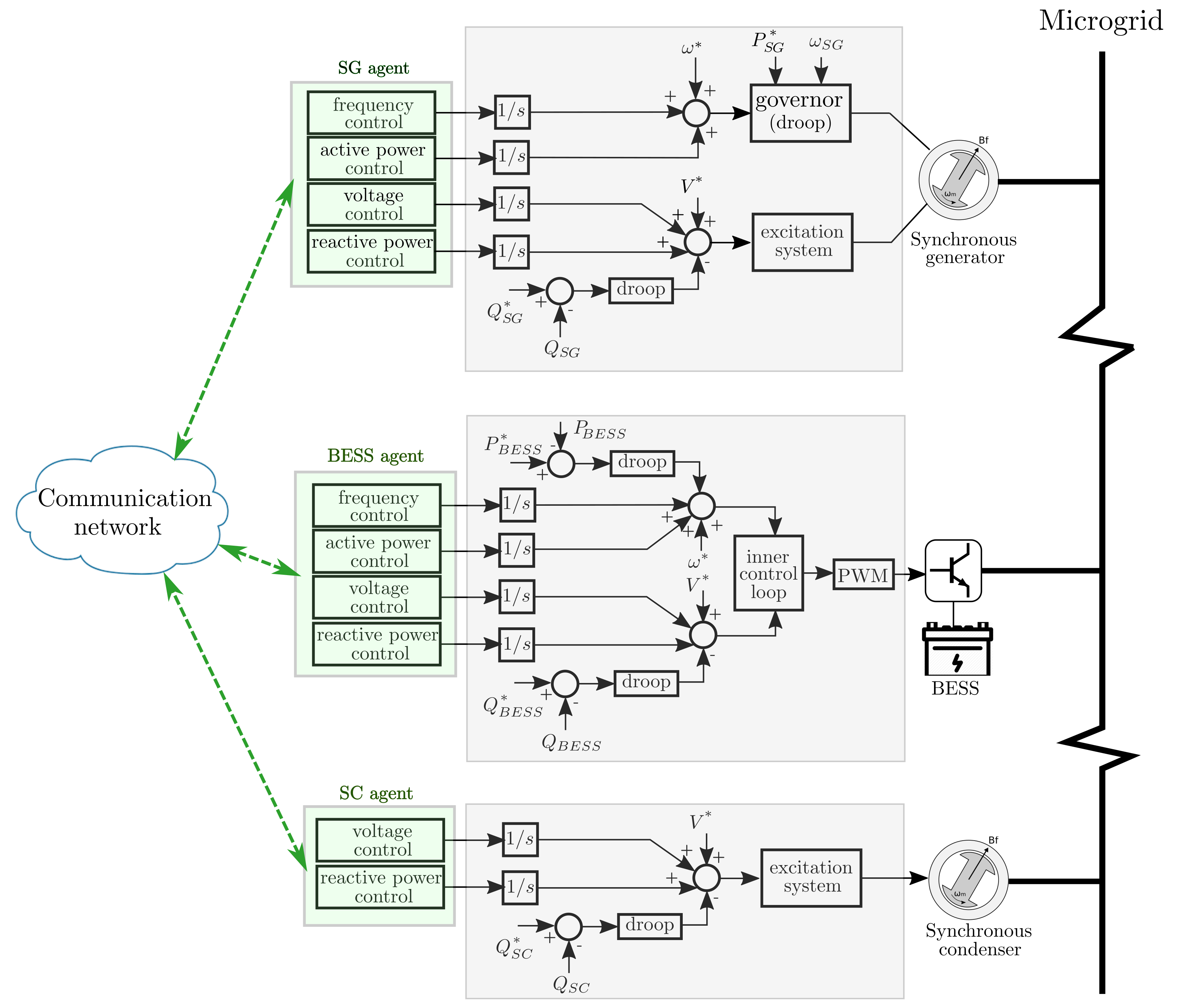
2.1. Primary Control

2.1.1. Synchronous Generators

The governor and turbine dynamics are modeled by speed-proportional control and first-order turbine dynamics, respectively:
P S G i = P S G i * 1 K S G i P ( ω S G i m ω S G i * )
τ g i P ˙ τ i = P S G i P τ i
where ω S G i * is the nominal frequency amplitude, K S G i P is the droop coefficient of S G i , P S G i m and P S G i * are the measured and reference active power output of S G i and τ g i is the low-pass filter parameter.
For the voltage control coordination, the SG voltages are adjusted following the droop law:
V S G i = V S G i * K S G i Q Q S G i m
where V S G i * is the nominal voltage amplitude, K S G i Q is the droop coefficient and Q S G i m is the SG measured reactive power output.

2.1.2. Power Inverter Control of BESSs

Each BESS unit consists of a battery system, a DC/AC inverter and an LCL filter to convert power from DC to AC and provide grid-side functionalities. The inverters operate in voltage control mode (grid-forming inverters).
The frequency and voltage of the inverter are tuned by the conventional droop characteristic:
ω B E S S i = ω B E S S i * K B E S S i P ( P B E S S i m P B E S S i * )
V B E S S i = V B E S S i * K B E S S i Q ( Q B E S S i * )
where ω B E S S i * and V B E S S i * are the nominal amplitude values of frequency and voltage, K B E S S i P and K B E S S i Q are droop factors, which are usually selected according to the rated output power, P B E S S i m and Q B E S S i m are the measured active and reactive powers and P B E S S i * and Q B E S S i * are the reference values of the power output.
The inner control loop includes a current control loop and a voltage control loop. In addition, a virtual impedance loop is also included to obtain accurate power sharing between individual units.

2.1.3. Synchronous Condensers

The SCs generate or absorb the reactive power to contribute to control voltage as well as share the reactive power of the system. Additionally, as a rotating machine, SC can provide a natural inertial response and short-circuit current to support ROCOF and system strength.
V S C i = V S C i * K S C i Q Q S C i m
where V S C i * is the nominal voltage amplitude, K S C i Q is the droop factor, which is determined by the maximum and minimum reactive power of S C i , and Q S G i m is the SG measured reactive power output.

2.2. Secondary Control

The primary control presented in the previous section responds quickly to adapt to any changes and stabilize the system. However, as a consequence of the droop control, the voltage and frequency deviation are appeared. In this section, we present the distributed secondary control to restore the system to a normal state. The frequency is regulated by SGs and BESSs inverters, while all DERs are coordinated to control bus voltages. Each DER controller sends and collects information with connected DERs based on communication infrastructure topology. The communication network between the DERs is represented by a graph, whose set of nodes corresponds to the set of DER buses G and the set of edges E = G .
Distributed secondary control is developed to accomplish four goals: (1) frequency restoration, (2) average voltage restoration, (3) accurate sharing of active power between SGs and BESSs and (4) accurate sharing of reactive power between SGs, BESSs and SCs.
lim t | ω * ω i ( t ) | = 0
lim t | K i P P i ( t ) K j P P j ( t ) | = 0
lim t | V * 1 N S G + N B E S S + N S C i = 1 N S G + N B E S S + N S C V i ( t ) | = 0
lim t | K i Q Q i ( t ) K j Q Q j ( t ) | = 0
From the presented primary control, the frequency and voltage set-points will be adjusted to achieve the secondary control objectives. The consensus-based algorithm is used to mitigate frequency and voltage discrepancies between adjacent DERs. The secondary frequency control function is constructed as follows:
u ˙ i ω = c ω j = 1 N S G + N B E S S [ a i j ( ω j ω i ) + g j ( ω * ω i ) ]
For the compromise between accurate reactive power sharing and voltage regulation, there is an immediate phase to estimate the weighted average bus voltages, after which the restoration process will be implemented. First, the estimation of the average voltage value V i ¯ of each DER is done in a distributed way through a dynamic consensus algorithm. By using the neighbours’ estimation V j ¯ , and information from the local voltage measurement V i , the output V i ¯ is updated at DER i:
V i ¯ ˙ = V i ¯ + j = 1 N S G + N B E S S + N S C a i j [ V ¯ j V ¯ i ]
The voltages are then restored by observing the calculated average voltages:
u ˙ i V = c V [ V * V i ]
The arbitrary active and reactive power sharing:
u ˙ i P = c P j = 1 N S G + N B E S S a i j [ K j p P j K i p P i ]
u ˙ i Q = c Q j = 1 N S G + N B E S S + N S C a i j [ K j Q Q j K i Q Q i ]
where c ω , c V , c P and c Q are control gains that used to regulate the speed of convergence process and a i j is the communication parameter between DERs i and j, a i j = 1 if ( i , j ) E ; otherwise, a i j = 0 .

2.3. Agent

In the proposed control framework, the primary controllers only need local information, while the secondary controllers require coordination with data exchange between controllers. In order to realize a realistic operation of the control system, the multi-agent system is used to implement the consensus algorithm to fulfill the secondary control goals. An agent is an entity capable of receiving measurements from local sensors, exchanging data with other agents via a communication network according to a specific protocol, processing calculations, and then sending appropriate signals back to lower-level controllers and actuators. Each agent is located at a DER and processes the consensus algorithm in a heterogeneous system. In the distributed scheme used in this work, instead of collecting all data to a central entity as a centralized approach, each agent only needs local and adjacent information, but can send signals back to the system level to achieve provided global goals. The communication network is established by sparse communication links between DERs, which contribute to the secondary process.
An agent is a program in python language and it runs independently and asynchronously in a Raspberry Pi to send secondary control signals to the corresponding local controller. The agents interact with the power system and exchange data with each other through a physical communication network with real characteristics. The implementation process of agents is presented in Algorithm 1. As shown in Figure 1, the SG agents and BESS agents exchange ω m , V m , P m , Q m information to join the process of regulating voltage and frequency set-points, while the SC agents exchange only V m , Q m to regulate the voltage set-point.
Algorithm 1: Agent i.
1
N i N 0 i     // ( determine if agents have a communication connection with agent i (
2
Receive local measurements at corresponding node i: { ω i m , V i m , P i m , Q i m } for SG and BESS agents, V i m , Q i m for SC agents
3
Send the local information to all neighbors
4
Acquire data from all neighborhood agents: { ω j , V j , P j , Q j } for SG and BESS agents, { V j , Q j } for SC agents
5
Proceed with the consensus algorithm to compute control signals: { u i P , u i ω , u i V , u i Q } for SG and BESS agents, { u i V , u i Q } for SC agents   //  ( control laws (11)–(15) (
6
Send the control signals to the local controller
7
restart from step 1

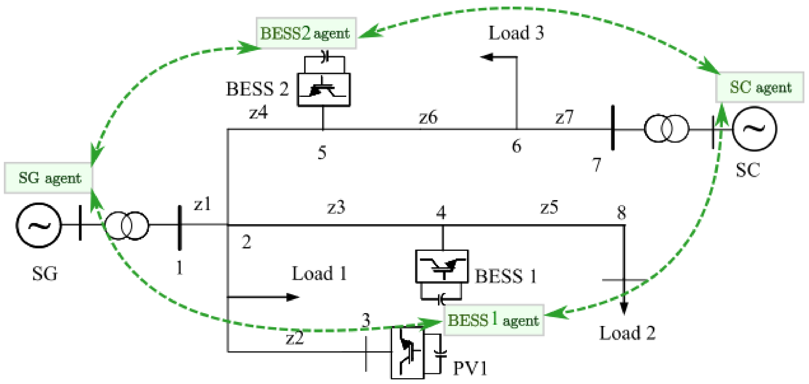
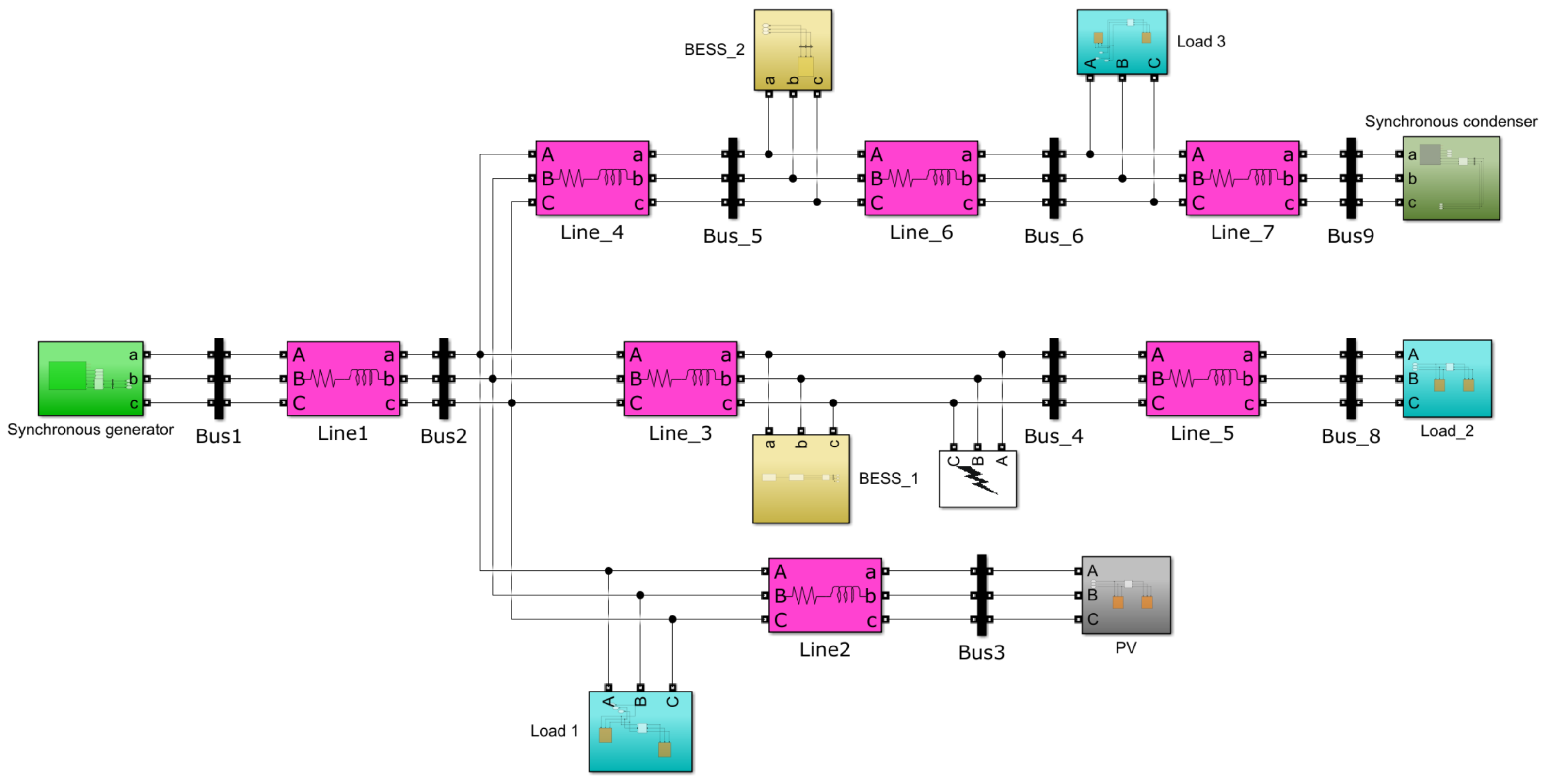
3. The Studied System

A single line diagram of a 20-kV microgrid system is modeled in MATLAB/Simulink, as shown in Figure 2 and Figure 3, which includes two BESSs, one PV, one synchronous generator (SG), one SC and three loads, with the detail parameter listed in Table 1 and Table 2. In the distributed secondary control, two BESSs, one SG and one SC are coordinated to provide services that help MG achieves global control goals of maintaining frequency/voltage and sharing active/reactive power after disturbances happened.
For the implementation of the experiment, we use four Raspberry PIs to run four agents, corresponding to four DERs used in this test case grid. The agents receive local measurements from grid simulation, then communicate with other agents using gRPC, a modern open-source high-performance Remote Procedure Call (RPC) framework. After that, agents process the consensus algorithm and send control signals to local controllers. The topology for the communication between agents is shown in Figure 2.

4. Results

In order to validate the proposed control, three cases are examined. Firstly, the system responses during a load step increase and three-phase short circuit fault scenario with and without SC in operation are plotted to compare the role of SC in frequency and voltage stability enhancement in the inertial and primary control stages. The second case is to validate how the proposed distributed secondary control works when the disturbance occurs. Finally, the last case is to validate how the proposed distributed control performs with the variation of a real PV power profile.

4.1. With and without SC in Operation
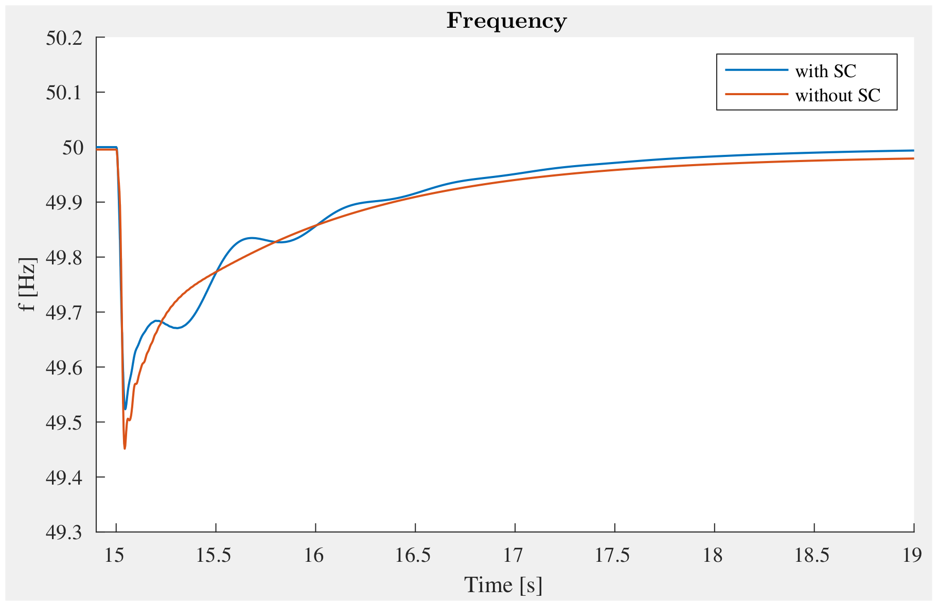
In order to experience the dynamic performance of SC for frequency and voltage support for the MGs, a load step change and a three-phase short circuit fault are examined to compare the system response with and without SC in operation.
  • Load step change:
    In this part, a 6-MW load increase disturbance happens at t = 15 s; the results show the comparison with and without SC in the distributed secondary control. Figure 4, Figure 5 and Figure 6 show the comparison of the system responses in both operation cases. As can be clearly seen from these figures, the system responses have been significantly improved with SC. With the inertial response from SC, the ROCOF of the system is enhanced dramatically from 26 Hz/s to 18 Hz/s, while the frequency nadir is not that significant but still improved. It can be explained that SC is only participating in the inertial response to help ROCOF at the onset of the disturbance. The same pattern is observed on the voltage magnitude at bus 6, as shown in Figure 5; the voltage magnitude has improved both pre- and post-disturbance with SC in the operation. Figure 6 shows the frequency response; it can clearly be seen that when SC is in operation, the frequency nadir and the settling frequency values are better than without SC.
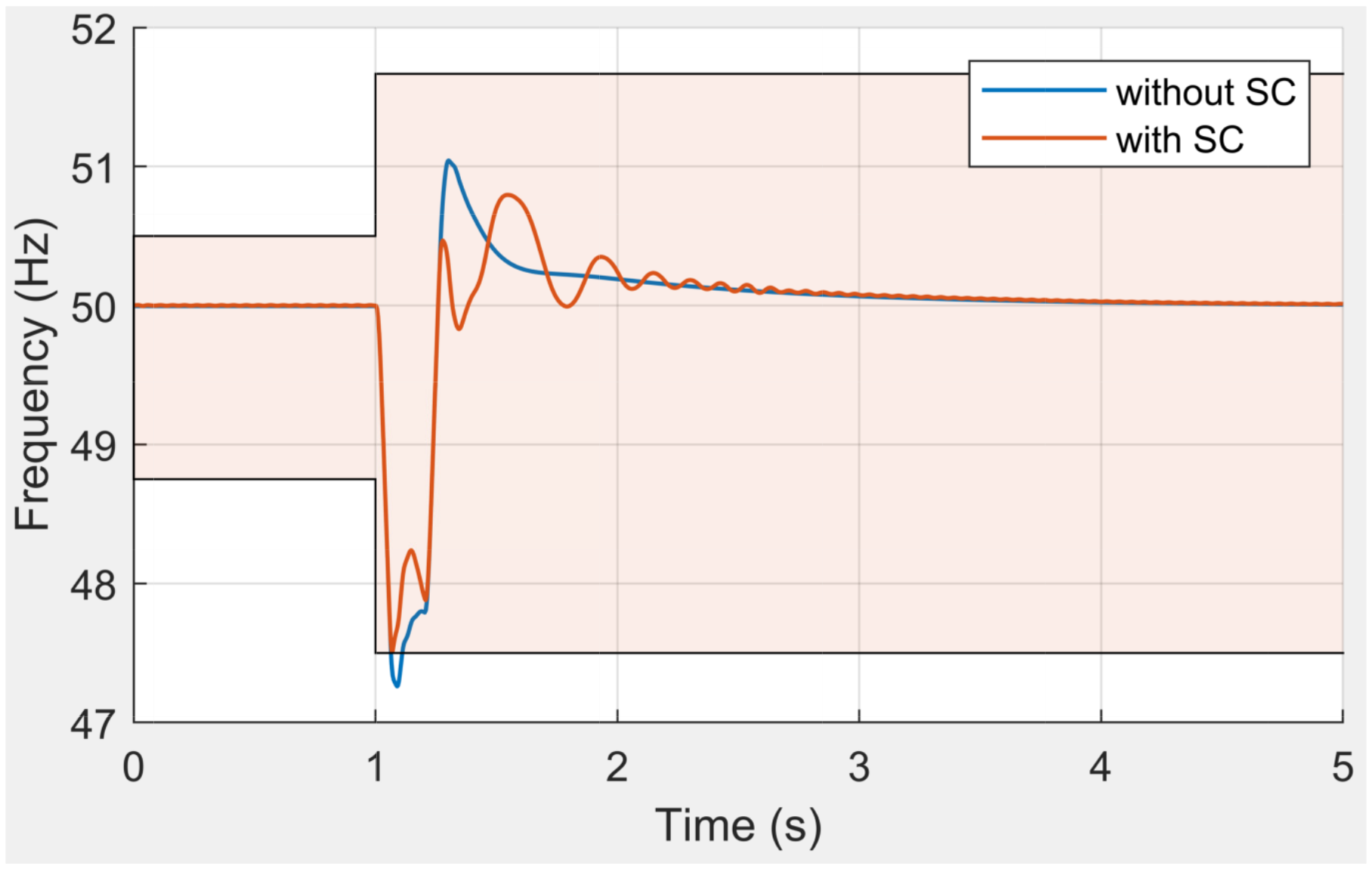
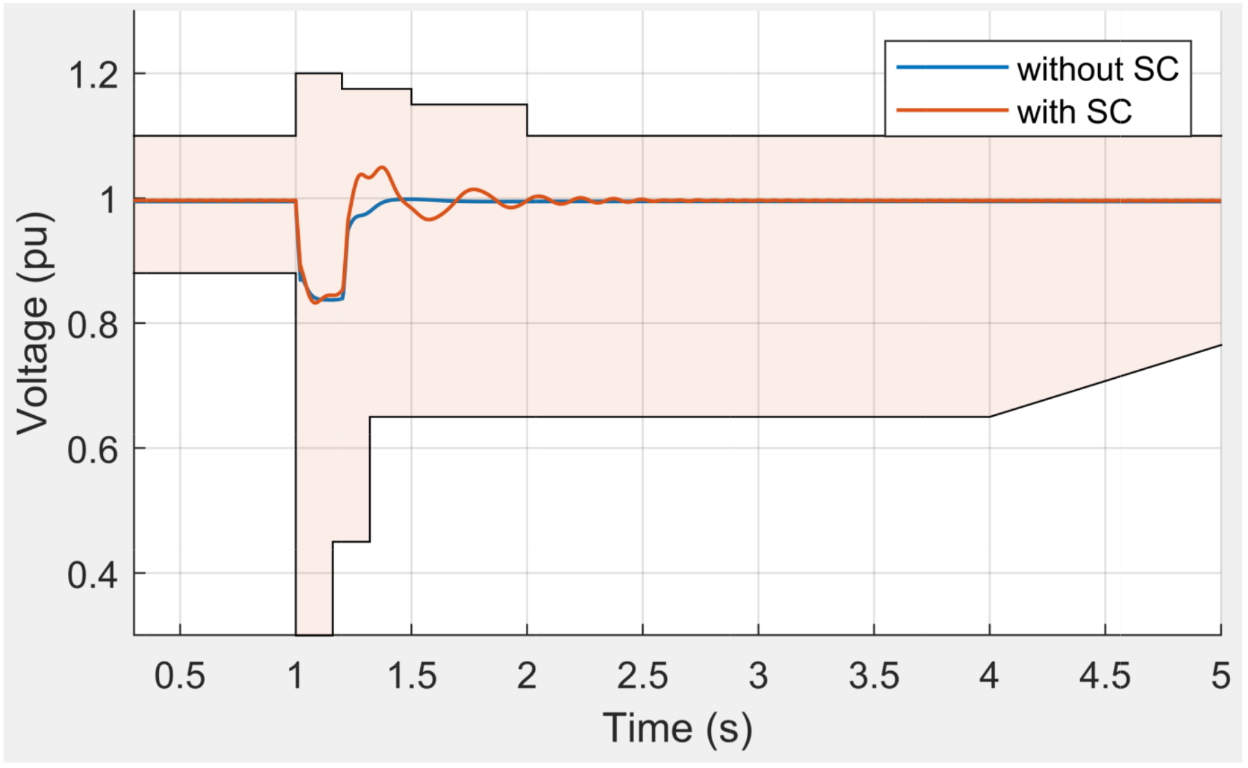
  • Three phase short circuit fault:
    In this section, a scenario with a three-phase short circuit fault is considered. The fault event occurs at bus 4 at t = 1 s and it is cleared after 200 ms with fault impedance R f = 7 Ω . Figure 7 and Figure 8 show the comparison results of system frequency and voltage in both cases of using and not using SC to highlight the contribution of SC in supporting system stability. The IEEE 1547-2018 standard is also expressed in the figures to check the fault ride-through ability of DER integration. It can be seen that with SC, the frequency is within the allowable range, while it is out of the range with a large over/undershoot without SC. The voltages in both cases are still satisfied with the requirement. With the given value of fault impedance, the voltage does not drop much [18], around 0.83 pu, as shown in Figure 8. As a result, we do not see a significant contribution of SC for voltage support here. It can be concluded that in the fault condition, SC helps the system to enhance frequency stability.

4.2. Distributed Secondary Control

In the aforementioned analysis, the distributed secondary control contributes to (i) frequency restoration, (ii) average voltage restoration, (iii) arbitrary active power-sharing among SGs and BESSs and (iv) arbitrary reactive power sharing among all SGs, BESSs and SCs. In this section, the comparison results show how the proposed control method can achieve these objectives. The results without secondary control are also included to have comparisons.
(i)
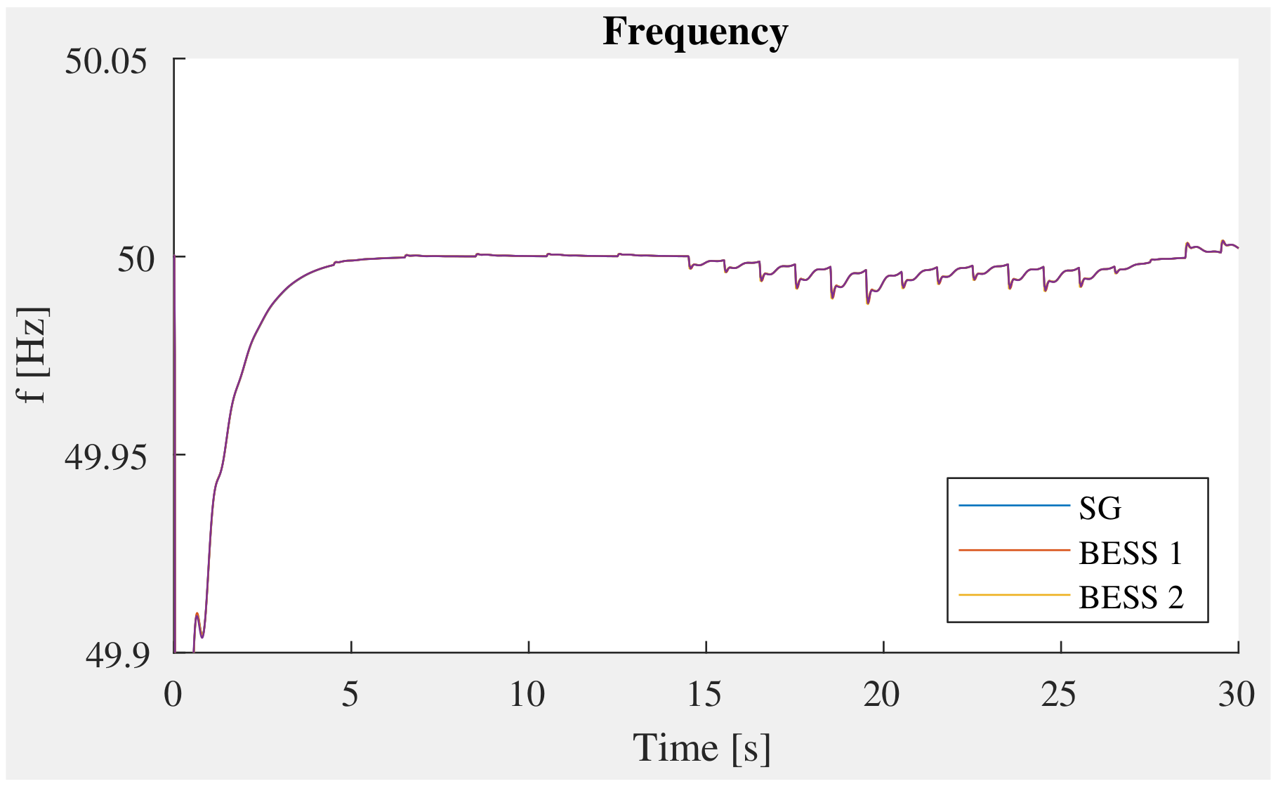
Frequency restoration: it can be seen from Figure 9 that, with the proposed distributed secondary control (blue line), the frequency is rapidly recovered to the nominal value (50 Hz), while in the case without the secondary controller, the frequency deviation is not mitigated and the frequency remains at 49.5 Hz after the load increase disturbance.
(ii)
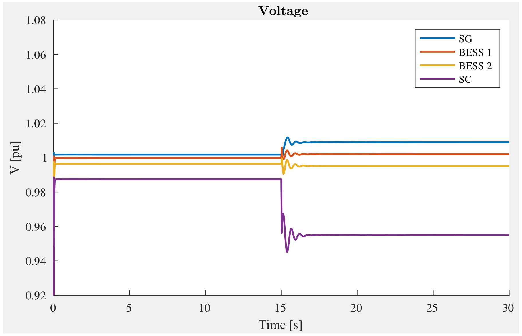
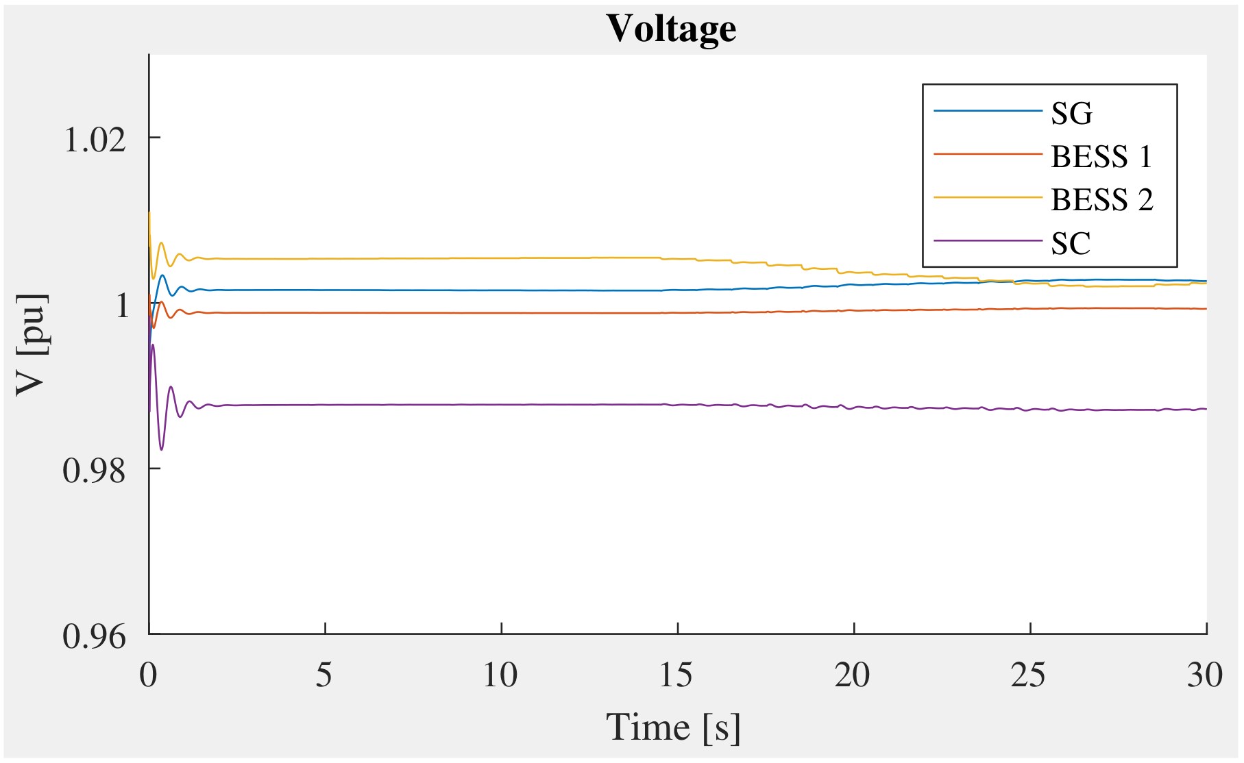
Average voltage restoration: Figure 10 shows how the average voltage can be quickly brought back to the nominal value with the proposed control. However, the average value is approximately 0.98 pu when the system operates without the proposed control. Figure 11 shows the actual voltages measured at DER buses, which are controlled within thresholds.
(iii)
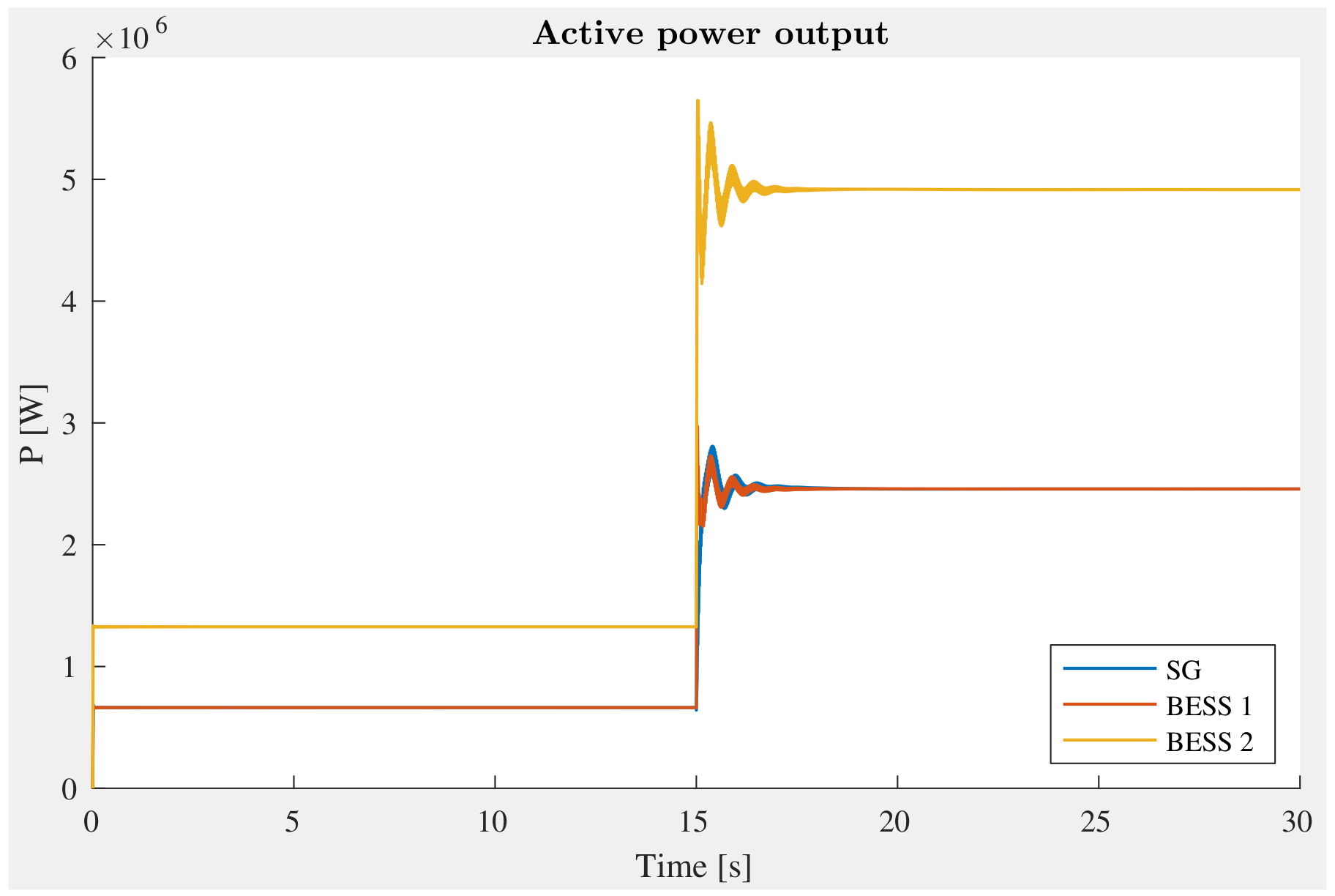
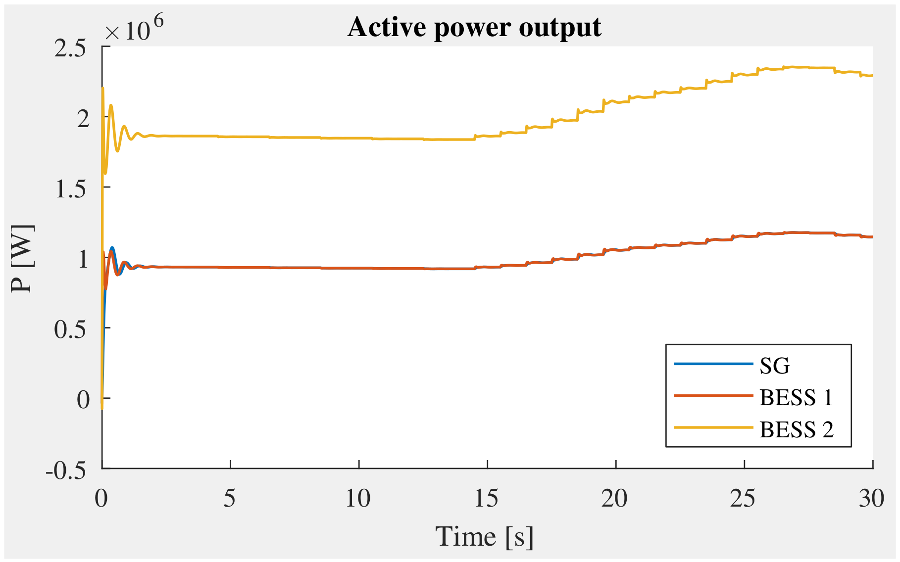
Arbitrary active power-sharing among SGs and BESSs: the active power of two BESSs and one SG rapidly respond to share the power imbalance of the system, as shown in Figure 12. Here, we notice that SG and BESS 1 have the same droop control gain, then as expected, they share the same amount of active power contribution, while that of BESS 2 is double, as seen in Figure 12. The secondary control ensures the accuracy of power-sharing as the initial design.
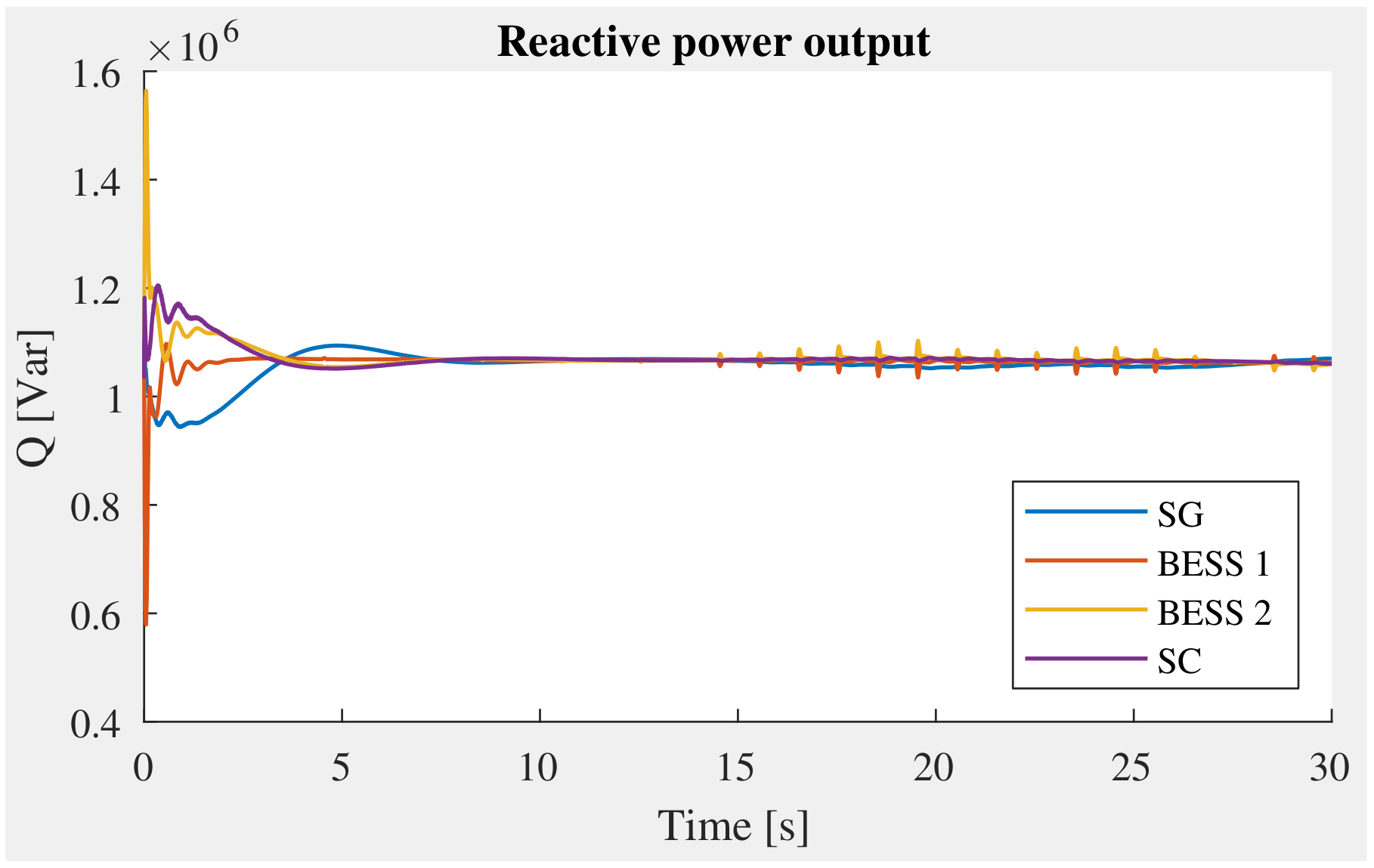
(iv)
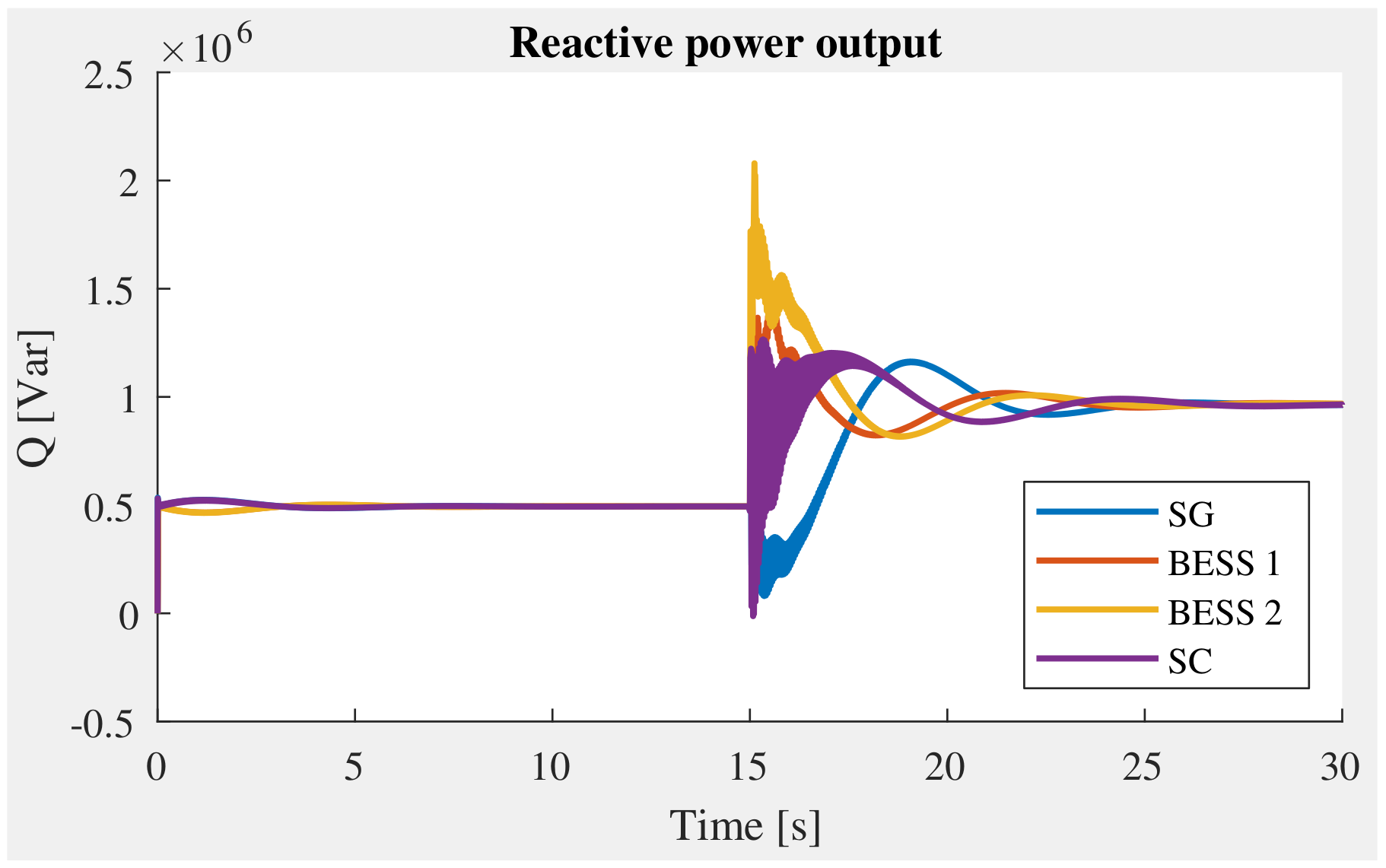
Arbitrary reactive power sharing among all SGs, BESSs and SCs: Figure 13 shows the reactive power contribution from different resources participating in the control. It can be seen clearly that the responses from BESSs are faster than that of SC and SG. This can be explained by the fast response of power converter control in comparison with rotating machines, which need more time for the excitation system to accelerate its electromagnetic field. The settling time of BESSs is also shorter than that of the rotating machines.

4.3. Test Case with a Renewable Energy Resource

The performance of the proposed method is further validated by connecting the test case system to a PV system with real data profiles. The active power output profile of PV is shown in Figure 14 for a 30 s duration. As seen clearly from the figure, the active power of PV gradually reduces at t = 15 s from 2.6 MW to 1.6 MW within approximately 12 s and then starts to increase. With the integration of the PV system into the grid, the control objectives are still achieved. The frequency and voltage are kept at rated values, as shown in Figure 15 and Figure 16. The active and reactive power outputs of DERs are shared proportionally following the droop coefficients of controllers (Figure 17 and Figure 18).

4.4. Discussions

From two disturbances scenarios, it is obvious that SC can contribute to the inertial response and the secondary control to bring the frequency and voltage back to nominal values. With the proposed distributed secondary control, four objectives are rapidly achieved after the load increase disturbance. From the comparison results, we can coordinate different types of generations that have different operation mechanisms for distributed secondary control, which is a new concept in this work.

5. Conclusions

The transition from centralized generation to small dispersed DERs at medium and lower voltage levels in distribution systems has introduced the concept of microgrids as a controllable entity within the next-generation power system. Microgrids highly rely on communication and control to meet their operational constraints and optimization goals. The research community has been moving toward distributed control for MGs to avoid the computational and communication burdens due to the increased number of DERs in the system. This paper proposed a distributed secondary control framework for MGs using SC coordinated with different DER units. With SC participating in the distributed control, system frequency and voltage have been significantly improved and rapidly recovered to the nominal values after the disturbances. Additionally, the power response from converter control of BESSs shows that ramping rate of converter-based resources is much faster than that of rotating machines. Meanwhile, the inertial response of the rotating machine helps ROCOF and system strength enhanced dramatically. The combination of SC and DERs in the distributed control framework for MGs not only helps the system frequency and voltage rapidly recover to nominal values, but also enhances the ROCOF and system strength. Realization by a multi-agent system is implemented to validate the proposed control approach that makes the proof-of-concept proposed closer to the field development.

Author Contributions

Conceptualisation, T.L.N. and H.T.N.; methodology, T.L.N., H.T.N. and Y.W.; writing—review and editing, T.L.N. and H.T.N.; software, T.L.N. and Y.W.; validation, T.L.N., H.T.N. and Y.W.; data curation, T.L.N. and H.T.N.; visualisation, T.L.N. and H.T.N.; writing—original draft preparation, T.L.N. and H.T.N.; project administration, O.A.M. and E.A.; supervision, O.A.M. and E.A. All authors have read and agreed to the published version of the manuscript.

Funding

This work received funding from the Eversource Energy Center—University of Connecticut.

Institutional Review Board Statement

Not applicable.

Informed Consent Statement

Not applicable.

Data Availability Statement

Not applicable.

Conflicts of Interest

The authors declare no conflict of interest.

Abbreviations

The following abbreviations are used in this manuscript:
DERsDistributed Energy Resources
SCsSynchronous Condensers
MGsMicrogrids
MGCCMicrogrid Central Controller
SCLShort Circuit Level
PLLPhase-Locked Loop
BESSsBattery Energy Storage Systems
ROCOFRate of Change of Frequency
DCDirect current
ACAlternative current

References

  1. Nguyen, H.T.; Guerriero, C.; Yang, G.; Boltonand, C.J.; Rahman, T.; Jensen, P.H. Talega SynCon—Power Grid Support for Renewable-based Systems. In Proceedings of the 2019 SoutheastCon, Huntsville, AL, USA, 11–14 April 2019; pp. 1–6. [Google Scholar] [CrossRef]
  2. Nguyen, H.T.; Yang, G.; Nielsen, A.H.; Jensen, P.H. Combination of Synchronous Condenser and Synthetic Inertia for Frequency Stability Enhancement in Low-Inertia Systems. IEEE Trans. Sustain. Energy 2019, 10, 997–1005. [Google Scholar] [CrossRef] [Green Version]
  3. Payerl, C. Synchronous Condensers Rediscovered—A New Way to Strengthen Grids. Technical Report. 2021. Available online: https://library.e.abb.com/public/c8adfa0169c44de3b6ed8ba186121922/Synchronous_condensers_rediscovered_Jun_2021.pdf (accessed on 17 January 2022).
  4. Nguyen, H.T.; Yang, G.; Nielsen, A.H.; Jensen, P.H.; Pal, B. Applying Synchronous Condenser for Damping Provision in Converter-dominated Power System. J. Mod. Power Syst. Clean Energy 2021, 9, 639–647. [Google Scholar] [CrossRef]
  5. Bao, L.; Fan, L.; Miao, Z. Comparison of Synchronous Condenser and STATCOM for Wind Farms in Weak Grids. In Proceedings of the 2020 52nd North American Power Symposium (NAPS), Tempe, AZ, USA, 11–13 April 2021; pp. 1–6. [Google Scholar] [CrossRef]
  6. Surya, A.S.; Partahi Marbun, M.; Marwah, M.; Mangunkusumo, K.; Harsono, B.B.S.; Bernando Tambunan, H. Study of Synchronous Condenser Impact in Jawa-Madura-Bali System to Provide Ancillary Services. In Proceedings of the 2020 12th International Conference on Information Technology and Electrical Engineering (ICITEE), Yogyakarta, Indonesia, 6–8 October 2020; pp. 234–238. [Google Scholar] [CrossRef]
  7. Fan, X.; Youbin, Z.; Lin, R.; Kunpeng, Z.; Tao, W.; Kan, C.; Yuze, R. Study on Transient Reactive Power Characteristics of New-Generation Large Synchronous Condenser. In Proceedings of the 2018 China International Conference on Electricity Distribution (CICED), Tianjin, China, 17–19 September 2018; pp. 1851–1855. [Google Scholar] [CrossRef]
  8. Yazdanian, M.; Mehrizi-Sani, A. Distributed Control Techniques in Microgrids. IEEE Trans. Smart Grid 2014, 5, 2901–2909. [Google Scholar] [CrossRef]
  9. Wang, Y.; Nguyen, T.L.; Syed, M.H.; Xu, Y.; Guillo-Sansano, E.; Nguyen, V.H.; Burt, G.M.; Tran, Q.T.; Caire, R. A Distributed Control Scheme of Microgrids in Energy Internet Paradigm and Its Multisite Implementation. IEEE Trans. Ind. Inform. 2021, 17, 1141–1153. [Google Scholar] [CrossRef] [Green Version]
  10. Wang, Y.; Nguyen, T.L.; Xu, Y.; Li, Z.; Tran, Q.T.; Caire, R. Cyber-Physical Design and Implementation of Distributed Event-Triggered Secondary Control in Islanded Microgrids. IEEE Trans. Ind. Appl. 2019, 55, 5631–5642. [Google Scholar] [CrossRef]
  11. Guo, F.; Wen, C.; Mao, J.; Song, Y.D. Distributed Secondary Voltage and Frequency Restoration Control of Droop-Controlled Inverter-Based Microgrids. IEEE Trans. Ind. Electron. 2015, 62, 4355–4364. [Google Scholar] [CrossRef]
  12. Simpson-Porco, J.W.; Shafiee, Q.; Dörfler, F.; Vasquez, J.C.; Guerrero, J.M.; Bullo, F. Secondary Frequency and Voltage Control of Islanded Microgrids via Distributed Averaging. IEEE Trans. Ind. Electron. 2015, 62, 7025–7038. [Google Scholar] [CrossRef]
  13. Schiffer, J.; Seel, T.; Raisch, J.; Sezi, T. Voltage Stability and Reactive Power Sharing in Inverter-Based Microgrids with Consensus-Based Distributed Voltage Control. IEEE Trans. Control. Syst. Technol. 2016, 24, 96–109. [Google Scholar] [CrossRef] [Green Version]
  14. Babayomi, O.; Li, Z.; Zhang, Z. Distributed secondary frequency and voltage control of parallel-connected vscs in microgrids: A predictive VSG-based solution. CPSS Trans. Power Electron. Appl. 2020, 5, 342–351. [Google Scholar] [CrossRef]
  15. Dehghan Banadaki, A.; Feliachi, A.; Kulathumani, V.K. Fully Distributed Secondary Voltage Control in Inverter-Based Microgrids. In Proceedings of the 2018 IEEE/PES Transmission and Distribution Conference and Exposition (T & D), Denver, CO, USA, 16–19 April 2018; pp. 1–9. [Google Scholar] [CrossRef] [Green Version]
  16. Espina, E.; Llanos, J.; Burgos-Mellado, C.; Cárdenas-Dobson, R.; Martínez-Gómez, M.; Sáez, D. Distributed Control Strategies for Microgrids: An Overview. IEEE Access 2020, 8, 193412–193448. [Google Scholar] [CrossRef]
  17. Vazquez Pombo, D. Cape Verde Reference Power System Data. 2021. Available online: https://data.dtu.dk/articles/dataset/Cape_Verde_Reference_Power_System_Data/13251524 (accessed on 17 January 2022).
  18. The Hoang, T.; Tuan Tran, Q.; Besanger, Y. An advanced protection scheme for medium-voltage distribution networks containing low-voltage microgrids with high penetration of photovoltaic systems. Int. J. Electr. Power Energy Syst. 2022, 139, 107988. [Google Scholar] [CrossRef]
Figure 1. The proposed distributed secondary control framework diagram for MGs.
Energies 15 02968 g001
Figure 2. Single line diagram of the studied MG.
Energies 15 02968 g002
Figure 3. Matlab/Simulink model.
Energies 15 02968 g003
Figure 4. Comparison of the rate of change of frequency.
Energies 15 02968 g004
Figure 5. Comparison of the voltage at bus 6.
Energies 15 02968 g005
Figure 6. Comparison of the frequency at bus 6.
Energies 15 02968 g006
Figure 7. Frequency response comparison during a fault case.
Energies 15 02968 g007
Figure 8. Voltage response comparison during a fault case.
Energies 15 02968 g008
Figure 9. System frequency.
Energies 15 02968 g009
Figure 10. Average voltage.
Energies 15 02968 g010
Figure 11. Voltage.
Figure 11. Voltage.
Energies 15 02968 g011
Figure 12. Active power output.
Energies 15 02968 g012
Figure 13. Reactive power output.
Energies 15 02968 g013
Figure 14. Active power PV.
Energies 15 02968 g014
Figure 15. Frequency.
Energies 15 02968 g015
Figure 16. Voltage.
Figure 16. Voltage.
Energies 15 02968 g016
Figure 17. Active power output.
Energies 15 02968 g017
Figure 18. Reactive power output.
Energies 15 02968 g018
Table 1. MG parameters [17].
P (MW)Q (MVAr)S (MVA)
SG 3
SC 3
BESS 13
BESS 26
PV13
Load 12.82.2
Load 23.52.7
Load 33.02.5
Table 2. Line parameters [17].
Resistance (Ohm)Reactance (Ohm)Line Name
0.970.384z1
0.850.298z2
0.4730.316z3
0.5480.224z4
1.0280.258z5
0.380.17z6
0.2790.182z7
Publisher’s Note: MDPI stays neutral with regard to jurisdictional claims in published maps and institutional affiliations.

