
Zonal-Based Optimal Microgrids Identification


Abstract
:1. Introduction
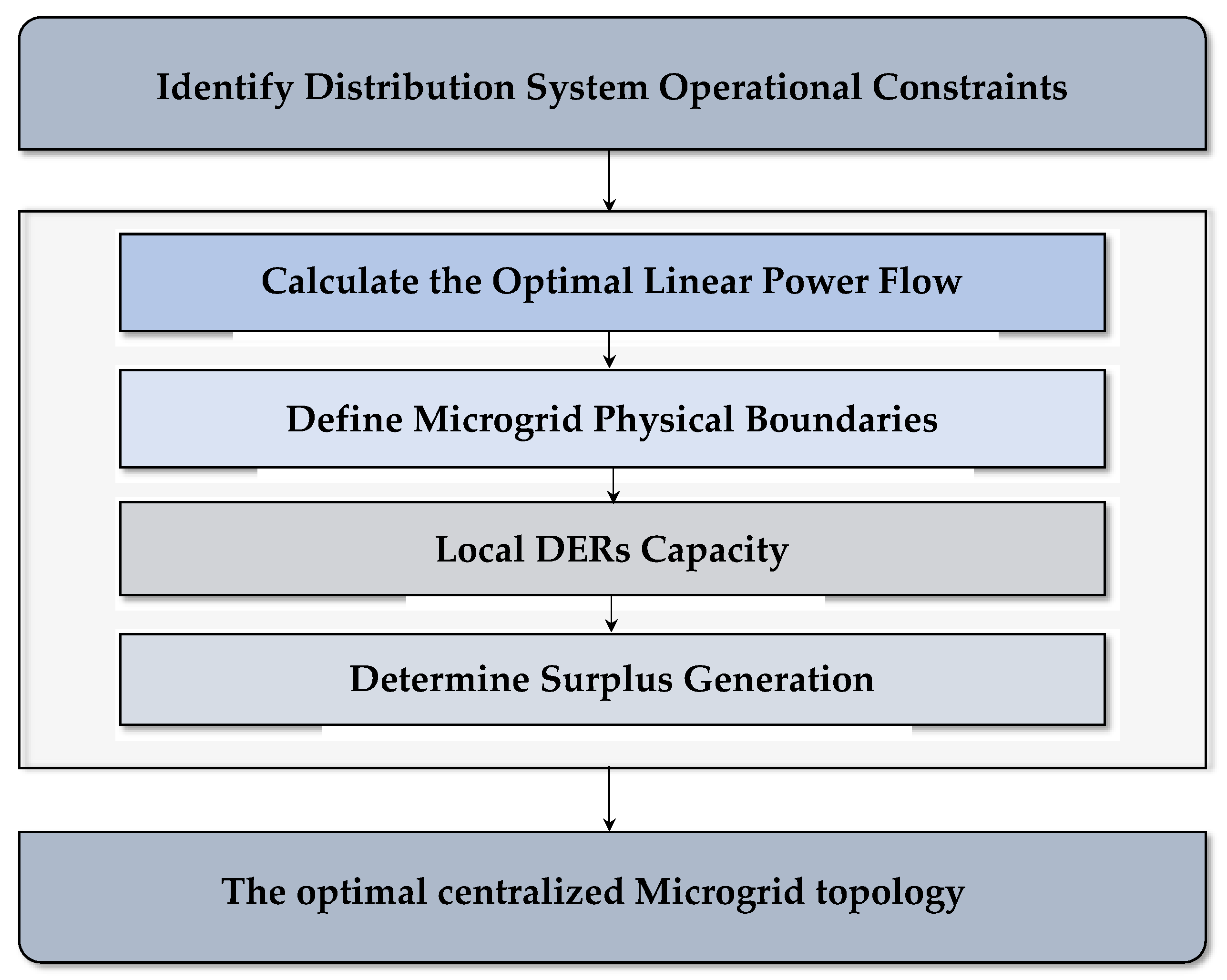
- A zonal-based microgrid identification model was developed to identify the optimal zone topology that is defined based on the optimal centralized microgrid physical boundaries;
- The model was developed as a mixed-integer linear programming (MILP) problem that effectively reduces the computational time and significantly decreases the complexity in solving the power flow optimization problem;
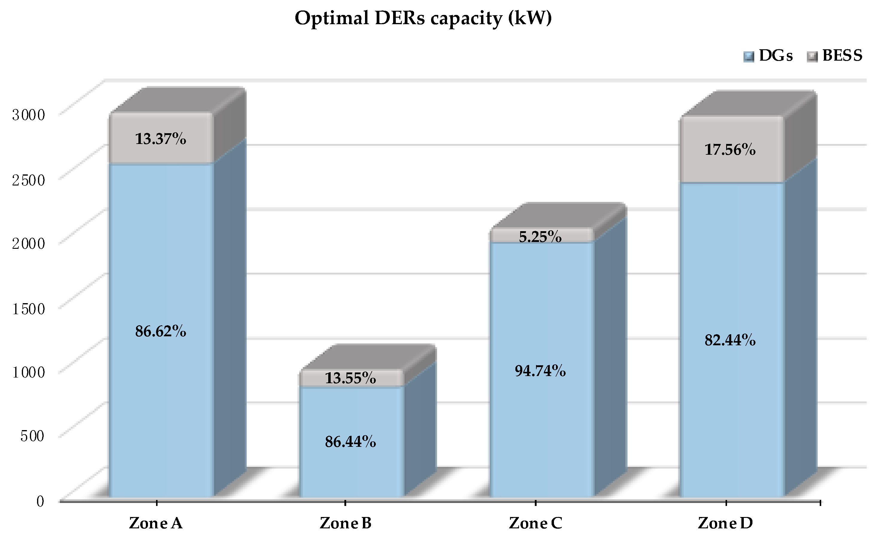
- The proposed optimization approach is capable of determining the optimal sizes and locations of the DERs that would be installed in the centralized microgrids. Moreover, the impact of incorporating the BESS was considered and analyzed.
2. Model Outline
3. Problem Formulation
3.1. Objective Function
3.2. Microgrid Topology Constraints
3.3. Linear Power Flow Constraints
3.4. Battery Energy Storage System
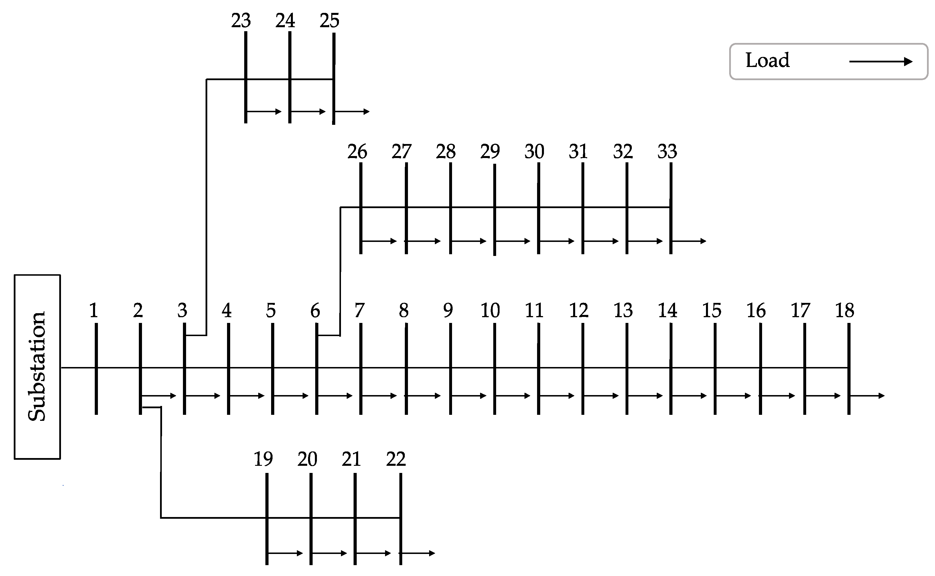
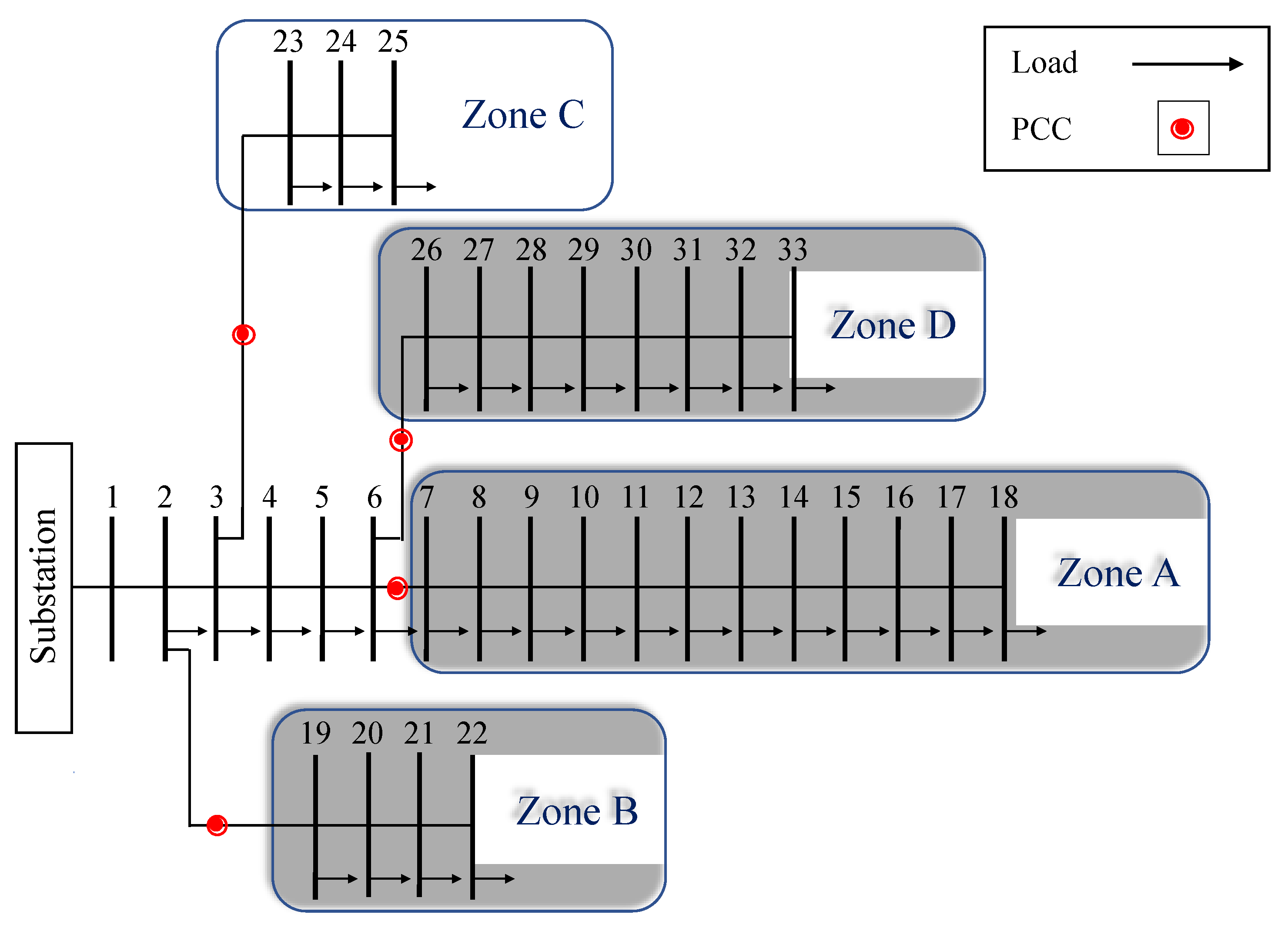
4. Numerical Simulations
5. Conclusions
Author Contributions
Funding
Institutional Review Board Statement
Informed Consent Statement
Data Availability Statement
Acknowledgments
Conflicts of Interest
Nomenclature
| Indices: | |
| c | Index for point of interconnection |
| ch | Superscript for energy storage charging mode |
| dch | Superscript for energy storage discharging mode |
| m,n | Index for buses |
| ∧ | Index for calculated variables |
| Sets: | |
| B | Set of buses |
| G | Set of points connected to upstream grid |
| L | Set of distribution lines |
| Lm | Set of distribution lines connected to bus m |
| Z | Set of zones |
| Parameters: | |
| b | Susceptance of the line between connected buses |
| ER,max | Maximum rated energy of BESS |
| ER,min | Minimum rated energy of BESS |
| Conductance of the line between connected buses | |
| PD | Load active power |
| PM,max | Maximum active power exchange with upstream grid |
| PR,max | Maximum rated power of BESS |
| PR,min | Minimum rated power of BESS |
| PLmax | Maximum active power flow between connected buses |
| QD | Load reactive power |
| QM,max | Maximum reactive power exchange with upstream grid |
| QLmax | Maximum reactive power flow between connected buses |
| ΔVmax | Maximum deviation in bus voltage magnitude |
| ΔVmin | Minimum deviation in bus voltage magnitude |
| HB | Stored energy at preceding hour |
| λ | Line length between connected buses |
| λmin | Minimum line length between connected buses |
| η | BESS efficiency |
| Variables: | |
| EB | Stored energy of BESS |
| ER | Rated energy of BESS |
| PB | Output power of BESS |
| Pch | Charged power of BESS |
| Pdch | Discharged power of BESS |
| PDER | Distributed energy resources active power |
| PM | Active power exchange with upstream grid |
| PR | Rated power of BESS |
| PL | Active power flow between connected buses |
| QDER | Distributed energy resources reactive power |
| QM | Reactive power exchange with upstream grid |
| QL | Reactive power flow between connected buses |
| Distribution bus connection state | |
| ΔV | Deviation in bus voltage magnitude |
| Δθ | Deviation in voltage angle |
| BESS discharging state | |
| BESS charging state |
References
- Vakulchuk, R.; Overland, I.; Scholten, D. Renewable energy and geopolitics: A review. Renew. Sustain. Energy Rev. 2020, 122, 109547. [Google Scholar] [CrossRef]
- Ajeigbe, O.A.; Munda, J.L.; Hamam, Y. Optimal allocation of renewable energy hybrid distributed generations for small-signal stability enhancement. Energies 2019, 12, 4777. [Google Scholar] [CrossRef] [Green Version]
- Alturki, M.; Khodaei, A. Marginal hosting capacity calculation for electric vehicle integration in active distribution networks. In Proceedings of the 2018 IEEE/PES Transmission and Distribution Conference and Exposition (T&D), Denver, CO, USA, 16–19 April 2018; pp. 1–9. [Google Scholar] [CrossRef]
- Elavarasan, R.M.; Shafiullah, G.M.; Padmanaban, S.; Kumar, N.M.; Annam, A.; Vetrichelvan, A.M.; Mihet-Popa, L.; Holm-Nielsen, J.B. A comprehensive review on renewable energy development, challenges, and policies of leading indian states with an international perspective. IEEE Access 2020, 8, 74432–74457. [Google Scholar] [CrossRef]
- Şerban, A.C.; Lytras, M.D. Artificial intelligence for smart renewable energy sector in Europe—Smart energy infrastructures for next generation smart cities. IEEE Access 2020, 8, 77364–77377. [Google Scholar] [CrossRef]
- Turner, J.A. A realizable renewable energy future. Science 1999, 285, 687–689. [Google Scholar] [CrossRef] [Green Version]
- Abbassi, R.; Abbassi, A.; Jemli, M.; Chebbi, S. Identification of unknown parameters of solar cell models: A comprehensive overview of available approaches. Renew. Sustain. Energy Rev. 2018, 90, 453–474. [Google Scholar] [CrossRef]
- Pravitasari, D.; Nisworo, S. New and renewable energy: A review and perspectives. In Proceedings of the 2017 IEEE International Conference on Sustainable Information Engineering and Technology (SIET), Malang, Indonesia, 24–25 November 2017; pp. 284–287. [Google Scholar]
- Pali, B.S.; Vadhera, S. Renewable energy systems for generating electric power: A review. In Proceedings of the 2016 IEEE 1st International Conference on Power Electronics, Intelligent Control and Energy Systems (ICPEICES), Delhi, India, 4–6 July 2016; pp. 1–6. [Google Scholar]
- Alturki, M.; Khodaei, A. Increasing distribution grid hosting capacity through optimal network reconfiguration. In Proceedings of the 2018 IEEE North American Power Symposium (NAPS), Fargo, ND, USA, 9–11 September 2018; pp. 1–6. [Google Scholar] [CrossRef]
- Puri, V.; Jha, S.; Kumar, R.; Priyadarshini, I.; Son, L.H.; Abdel-Basset, M.; Elhoseny, M.; Long, H.V. A hybrid artificial intelligence and internet of things model for generation of renewable resource of energy. IEEE Access 2019, 7, 111181–111191. [Google Scholar] [CrossRef]
- Marcos, F.P.; Domingo, C.M.; Román, T.G.S.; Arín, R.C. Location and sizing of micro-grids to improve continuity of supply in radial distribution networks. Energies 2020, 13, 3495. [Google Scholar] [CrossRef]
- Shahidehpour, M.; Clair, J.F. A functional microgrid for enhancing reliability, sustainability, and energy efficiency. Electr. J. 2012, 25, 21–28. [Google Scholar] [CrossRef]
- Albaker, A.; Khodaei, A. Elevating prosumers to provisional microgrids. In Proceedings of the 2017 IEEE Power & Energy Society General Meeting, Chicago, IL, USA, 16–20 July 2017; pp. 1–5. [Google Scholar]
- Justo, J.J.; Mwasilu, F.; Lee, J.; Jung, J.-W. AC-microgrids versus DC-microgrids with distributed energy resources: A review. Renew. Sustain. Energy Rev. 2013, 24, 387–405. [Google Scholar] [CrossRef]
- Alturki, M.; Khodaei, A.; Paaso, A.; Bahramirad, S. Optimization-based distribution grid hosting capacity calculations. Appl. Energy 2018, 219, 350–360. [Google Scholar] [CrossRef]
- Office of Electricity Delivery and Energy Reliability. DOE Microgrid Workshop Report. Summary Report 2012. Available online: https://www.energy.gov/sites/prod/files/Microgrid%20Workshop%20Report%20August%202011.pdf (accessed on 24 September 2021).
- Takano, H.; Goto, R.; Hayashi, R.; Asano, H. Optimization method for operation schedule of microgrids considering uncertainty in available data. Energies 2021, 14, 2487. [Google Scholar] [CrossRef]
- Albaker, A.; Khodaei, A. Valuation of microgrid unused capacity in islanded operation. In Proceedings of the 2017 North American Power Symposium (NAPS), Morgantown, WV, USA, 17–19 September 2017; pp. 1–6. [Google Scholar]
- Asano, H.; Hatziargyriou, N.; Iravani, R.; Marnay, C. Microgrids: An overview of ongoing research, development, and demonstration projects. IEEE Power Energy Mag. 2007, 5, 78–94. [Google Scholar]
- Albaker, A.; Khodaei, A. Optimal scheduling of integrated microgrids in holonic distribution grids. In Proceedings of the 2018 IEEE North American Power Symposium (NAPS), Fargo, ND, USA, 9–11 September 2018; pp. 1–6. [Google Scholar] [CrossRef]
- Khodaei, A. Provisional microgrids. IEEE Trans. Smart Grid 2014, 6, 1107–1115. [Google Scholar] [CrossRef]
- Ghalavand, F.; Alizade, B.A.M.; Gaber, H.; Karimipour, H. Microgrid islanding detection based on mathematical morphology. Energies 2018, 11, 2696. [Google Scholar] [CrossRef] [Green Version]
- Kroposki, B.; Lasseter, R.; Ise, T.; Morozumi, S.; Papathanassiou, S.; Hatziargyriou, N. Making microgrids work. IEEE Power Energy Mag. 2008, 6, 40–53. [Google Scholar] [CrossRef]
- Shahidehpour, M. Role of smart microgrid in a perfect power system. In Proceedings of the 2010 IEEE PES General Meeting, Minneapolis, MN, USA, 25–29 July 2010; p. 1. [Google Scholar]
- Khodaei, A. Microgrid optimal scheduling with multi-period islanding constraints. IEEE Trans. Power Syst. 2013, 29, 1383–1392. [Google Scholar] [CrossRef]
- Talapur, G.G.; Suryawanshi, H.M.; Xu, L.; Shitole, A.B. A reliable microgrid with seamless transition between grid connected and islanded mode for residential community with enhanced power quality. IEEE Trans. Ind. Appl. 2018, 54, 5246–5255. [Google Scholar] [CrossRef] [Green Version]
- Albaker, A.; Majzoobi, A.; Zhao, G.; Zhang, J.; Khodaei, A. Privacy-preserving optimal scheduling of integrated microgrids. Electr. Power Syst. Res. 2018, 163, 164–173. [Google Scholar] [CrossRef]
- Parhizi, S.; Lotfi, H.; Khodaei, A.; Bahramirad, S. State of the art in research on microgrids: A review. IEEE Access 2015, 3, 890–925. [Google Scholar] [CrossRef]
- Alam, M.N.; Chakrabarti, S.; Ghosh, A. Networked microgrids: State-of-the-art and future perspectives. IEEE Trans. Ind. Inform. 2018, 15, 1238–1250. [Google Scholar] [CrossRef]
- Hossain, E.; Kabalci, E.; Bayindir, R.; Perez, R. Microgrid testbeds around the world: State of art. Energy Convers. Manag. 2014, 86, 132–153. [Google Scholar] [CrossRef]
- Cagnano, A.; De Tuglie, E.; Mancarella, P. Microgrids: Overview and guidelines for practical implementations and operation. Appl. Energy 2020, 258, 114039. [Google Scholar] [CrossRef]
- Hasanvand, S.; Nayeripour, M.; Waffenschmidt, E.; Fallahzadeh-Abarghouei, H. A new approach to transform an existing distribution network into a set of micro-grids for enhancing reliability and sustainability. Appl. Soft Comput. 2017, 52, 120–134. [Google Scholar] [CrossRef]
- Di Fazio, A.R.; Russo, M.; De Santis, M. Zoning evaluation for voltage optimization in distribution networks with distributed energy resources. Energies 2019, 12, 390. [Google Scholar] [CrossRef] [Green Version]
- Osama, R.A.; Zobaa, A.F.; Abdelaziz, A.Y. A planning framework for optimal partitioning of distribution networks into microgrids. IEEE Syst. J. 2019, 14, 916–926. [Google Scholar] [CrossRef] [Green Version]
- Wang, G.; Wang, Q.; Qiao, Z.; Wang, J.; Anderson, S. Optimal planning of multi-micro grids based-on networks reliability. Energy Rep. 2020, 6, 1233–1249. [Google Scholar] [CrossRef]
- Tsikalakis, A.G.; Hatziargyriou, N.D. Centralized control for optimizing microgrids operation. IEEE Trans. Energy Convers. 2008, 1, 241–248. [Google Scholar] [CrossRef]
- Mojtahedzadeh, S.; Najafi-Ravadanegh, S.; Haghifam, M.R. A framework for optimal clustering of a greenfield distribution network area into multiple autonomous microgrids. J. Power Technol. 2016, 96, 219–228. [Google Scholar]
- Oh, Y.S.; Cho, G.J.; Kim, M.S.; Kim, J.S.; Bukhari, S.B.; Haider, R.; Zaman, M.S.; Kim, C.H. Zonal operation scheme of distributed generations for voltage regulation in distribution networks. In Proceedings of the International Conference on Power Systems Transients (IPST2017), Seoul, Korea, 26–29 June 2017; pp. 26–29. [Google Scholar]
- Li, P.; Liu, J.; Li, B.; Song, Y.; Zhong, J. Dynamic power system zone division scheme using sensitivity analysis. J. Int. Counc. Electr. Eng. 2014, 4, 157–161. [Google Scholar] [CrossRef]
- Pachanapan, P.; Anaya-Lara, O.; Dysko, A.; Lo, K.L. Adaptive zone identification for voltage level control in distribution networks with DG. IEEE Trans. Smart Grid 2012, 3, 1594–1602. [Google Scholar] [CrossRef]
- Meng, T.; Xu, M.; Zou, G.; Yang, J.; Zhang, J.; Lin, X. Voltage regulation based on hierarchical and district-dividing control for active distribution network. In Proceedings of the 2015 IEEE PES Asia-Pacific Power and Energy Engineering Conference (APPEEC), Brisbane, QLD, Australia, 15–18 November 2015; pp. 1–5. [Google Scholar] [CrossRef]
- Lotfi, H.; Ghazi, R.; Naghibi-Sistani, M.B. Multi-objective dynamic distribution feeder reconfiguration along with capacitor allocation using a new hybrid evolutionary algorithm. Energy Syst. 2020, 11, 779–809. [Google Scholar] [CrossRef]
- Lotfi, H.; Ghazi, R. Optimal participation of demand response aggregators in reconfigurable distribution system considering photovoltaic and storage units. J. Ambient Intell. Humaniz. Comput. 2021, 12, 2233–2255. [Google Scholar] [CrossRef]
- Lotfi, H. Multi-objective energy management approach in distribution grid integrated with energy storage units considering the demand response program. Int. J. Energy Res. 2020, 44, 10662–10681. [Google Scholar] [CrossRef]
- Di Fazio, A.R.; Russo, M.; de Santis, M. Zoning evaluation for voltage vontrol in smart distribution networks. In Proceedings of the IEEE International Conference on Environment and Electrical Engineering (EEEIC), Palermo, Italy, 12–15 June 2018. [Google Scholar]
- Kiran, D.; Abhyankar, A.R.; Panigrahi, B.K. Hierarchical clustering based zone formation in power networks. In Proceedings of the 2016 National Power Systems Conference (NPSC), Bhubaneswar, India, 19–21 December 2016; pp. 1–6. [Google Scholar]
- Pandit, M.; Srivastava, L.; Sharma, M.; Dubey, H.M.; Panigrahi, B.K. Large-scale multi-zone optimal power dispatch using hybrid hierarchical evolution technique. J. Eng. 2014, 2014, 71–80. [Google Scholar] [CrossRef]
- Islam, S.R.; Sutanto, D.; Muttaqi, K. Coordinated decentralized emergency voltage and reactive power control to prevent long-term voltage instability in a power system. IEEE Trans. Power Syst. 2014, 30, 2591–2603. [Google Scholar] [CrossRef]
- Cotilla-Sanchez, E.; Hines, P.D.; Barrows, C.; Blumsack, S.; Patel, M. Multi-attribute partitioning of power networks based on electrical distance. IEEE Trans. Power Syst. 2013, 28, 4979–4987. [Google Scholar] [CrossRef]
- Yuan, H.; Li, F.; Wei, Y.; Zhu, J. Novel linearized power flow and linearized OPF models for active distribution networks with application in distribution LMP. IEEE Trans. Smart Grid 2016, 9, 438–448. [Google Scholar] [CrossRef]
- Nikmehr, N.; Ravadanegh, S.N. Heuristic probabilistic power flow algorithm for microgrids operation and planning. IET Gener. Transm. Distrib. 2015, 9, 985–995. [Google Scholar] [CrossRef]
- ChithraDevi, S.; Lakshminarasimman, L.; Balamurugan, R. Stud krill herd algorithm for multiple DG placement and sizing in a radial distribution system. Eng. Sci. Technol. Int. J. 2017, 20, 748–759. [Google Scholar] [CrossRef] [Green Version]
- Ghasemi, S.; Moshtagh, J. Radial distribution systems reconfiguration considering power losses cost and damage cost due to power supply interruption of consumers. Int. J. Electr. Eng. Inform. 2013, 5, 297–315. [Google Scholar] [CrossRef]
- ILOG CPLEX Homepage. 2009. Available online: http://www.ilog.com (accessed on 21 May 2021).
- Mohamed, A.A.R.; El-Sharkawy, R.; Omran, W.A. Power management strategy to enhance the operation of active distribution networks. In Proceedings of the IEEE 2017 5th International Istanbul Smart Grid and Cities Congress and Fair (ICSG), Istanbul, Turkey, 19–21 April 2017; pp. 95–99. [Google Scholar]
- Murty, V.V.V.S.N.; Kumar, A. Optimal DG integration and network reconfiguration in microgrid system with realistic time varying load model using hybrid optimisation. IET Smart Grid 2019, 2, 192–202. [Google Scholar] [CrossRef]


| Zone | Quantity | Zone Configurations |
|---|---|---|
| Zone A | Bus # | 7, 8, 9, 10, 11, 12, 13, 14, 15, 16, 17, 18 |
| Line # | 7, 8, 9, 10, 11, 12, 13, 14, 15, 16, 17 | |
| PCC | Line 6 | |
| Total Distance (m) | 8650 | |
| Zone B | Bus # | 19, 20, 21, 22 |
| Line # | 19, 20, 21 | |
| PCC | Line 18 | |
| Total Distance (m) | 2600 | |
| Zone C | Bus # | 23, 24, 25 |
| Line # | 23, 24 | |
| PCC | Line 22 | |
| Total Distance (m) | 1800 | |
| Zone D | Bus # | 26, 27, 28, 29, 30, 31, 32, 33 |
| Line # | 26, 27, 28, 29, 30, 31 32 | |
| PCC | Line 25 | |
| Total Distance (m) | 4200 |
| Zone | Quantity | Operational Results |
|---|---|---|
| Zone A | DERs Capacity (kW) | 2590.40 |
| Total Distance (m) | 8650 | |
| Total Load (kW) | 1075 | |
| Percentage of Served Load (%) | 100 | |
| Surplus Generation (kW) | 1515.40 | |
| Zone B | DERs Capacity (kW) | 860.90 |
| Total Distance (m) | 2600 | |
| Total Load (kW) | 360 | |
| Percentage of Served Load (%) | 100 | |
| Surplus Generation (kW) | 500.90 | |
| Zone C | DERs Capacity (kW) | 1983.02 |
| Total Distance (m) | 1800 | |
| Total Load (kW) | 930 | |
| Percentage of Served Load (%) | 100 | |
| Surplus Generation (kW) | 1053.02 | |
| Zone D | DERs Capacity (kW) | 2442.16 |
| Total Distance (m) | 4200 | |
| Total Load (kW) | 920 | |
| Percentage of Served Load (%) | 100 | |
| Surplus Generation (kW) | 1522.16 |
| Zone | Quantity | Operational Results |
|---|---|---|
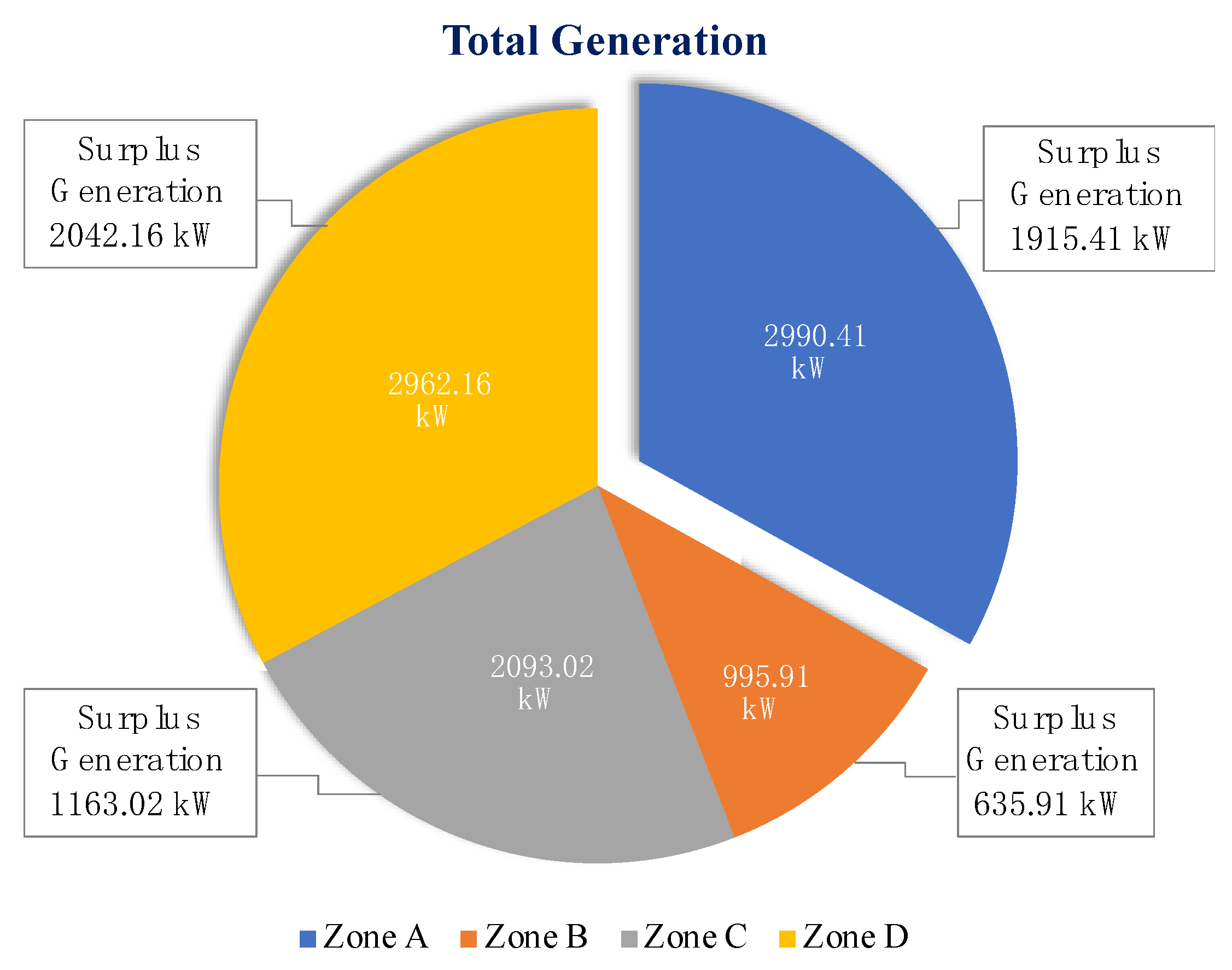
| Zone A | DERs Capacity (kW) | 2990.41 |
| Total Distance (m) | 8650 | |
| Total Load (kW) | 1075 | |
| Percentage of Served Load (%) | 15.44 | |
| Surplus Generation (kW) | 1915.41 | |
| Zone B | DERs Capacity (kW) | 995.91 |
| Total Distance (m) | 2600 | |
| Total Load (kW) | 360 | |
| Percentage of Served Load (%) | 15.68 | |
| Surplus Generation (kW) | 635.91 | |
| Zone C | DERs Capacity (kW) | 2093.02 |
| Total Distance (m) | 1800 | |
| Total Load (kW) | 930 | |
| Percentage of Served Load (%) | 5.54 | |
| Surplus Generation (kW) | 1163.02 | |
| Zone D | DERs Capacity (kW) | 2962.16 |
| Total Distance (m) | 4200 | |
| Total Load (kW) | 920 | |
| Percentage of Served Load (%) | 21.29 | |
| Surplus Generation (kW) | 2042.16 |
| Method | Zone Topology | Number of Iterations | Computational Time | Optimal DERs Capacity | Optimal Locations |
|---|---|---|---|---|---|
| Particle Swarm Optimization Algorithm (PSO) [56] | Zone 4 (buses 6–11, and 26) | 250 iterations | not stated | 1175 kW | bus 8 |
| Stud Krill herd Algorithm (SKHA) [53] | Entire distribution system | 100 iterations | 4.2406 s | 2590 kW | bus 6 |
| Gravitational Search Algorithm (GSA) [57] | Zone 3 (buses 9–18) | solved in two phases with many iterations (not stated) | not stated | 2589 kW | bus 6 |
| Proposed Method (Case 1) | Zone A (buses 7–18) | 1 iteration | 1.1321 s | 2590 kW | bus 7 |
| Proposed Method (Case 2) | Zone A (buses 7–18) | 1 iteration | 1.1327 s | 2990 kW | bus 7 |
Publisher’s Note: MDPI stays neutral with regard to jurisdictional claims in published maps and institutional affiliations. |
© 2022 by the authors. Licensee MDPI, Basel, Switzerland. This article is an open access article distributed under the terms and conditions of the Creative Commons Attribution (CC BY) license (https://creativecommons.org/licenses/by/4.0/).
Share and Cite
Albaker, A.; Alturki, M.; Abbassi, R.; Alqunun, K. Zonal-Based Optimal Microgrids Identification. Energies 2022, 15, 2446. https://doi.org/10.3390/en15072446
Albaker A, Alturki M, Abbassi R, Alqunun K. Zonal-Based Optimal Microgrids Identification. Energies. 2022; 15(7):2446. https://doi.org/10.3390/en15072446
Chicago/Turabian StyleAlbaker, Abdullah, Mansoor Alturki, Rabeh Abbassi, and Khalid Alqunun. 2022. "Zonal-Based Optimal Microgrids Identification" Energies 15, no. 7: 2446. https://doi.org/10.3390/en15072446