
The Route from Green H2 Production through Bioethanol Reforming to CO2 Catalytic Conversion: A Review

 ,
,  ,
, 
 ,
,  ,
,  and
and
Abstract
:1. Introduction
2. Catalysis for Sustainable Processes
2.1. H2 Production from Renewables: Bioethanol Reforming
2.1.1. Catalytic Formulations
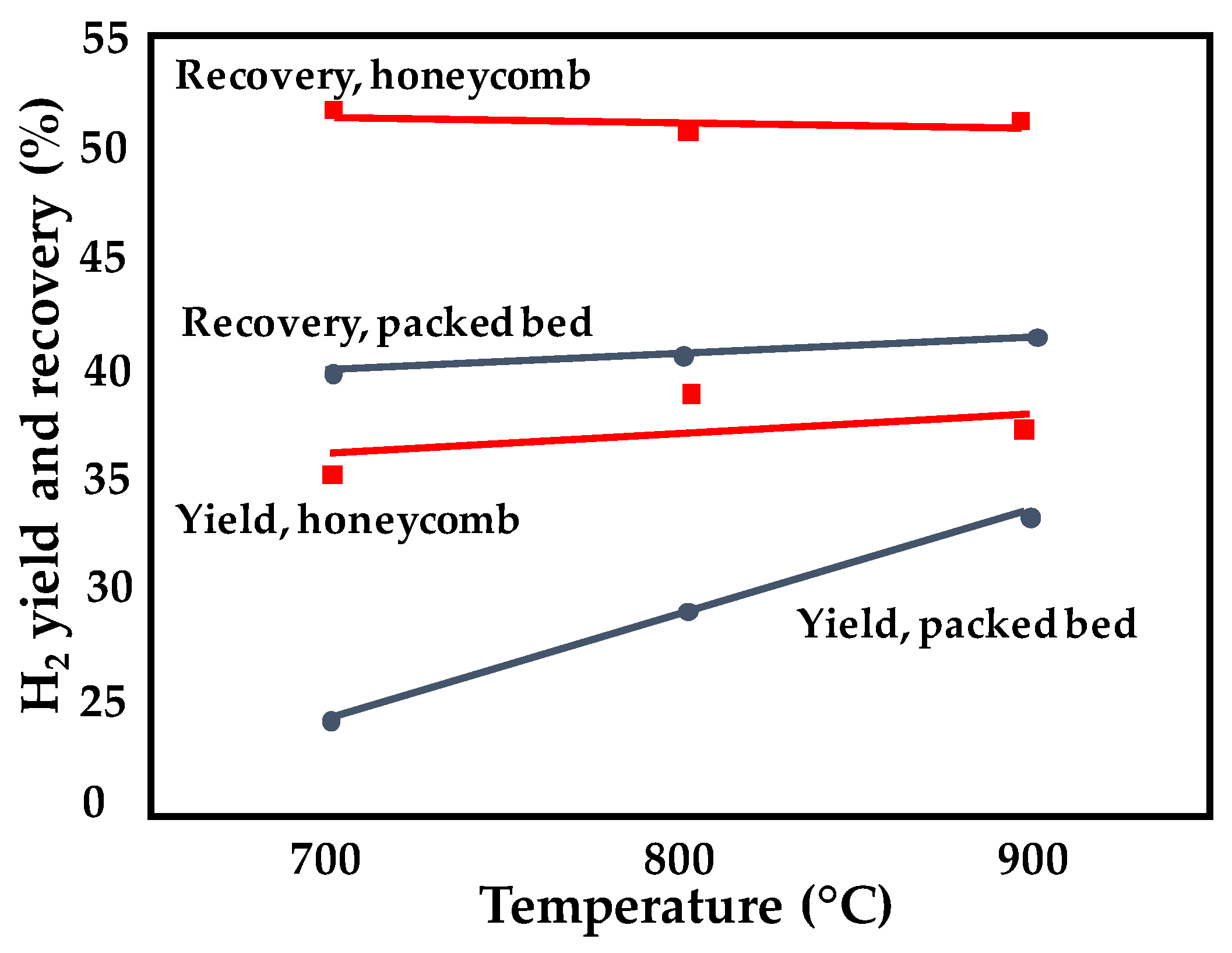
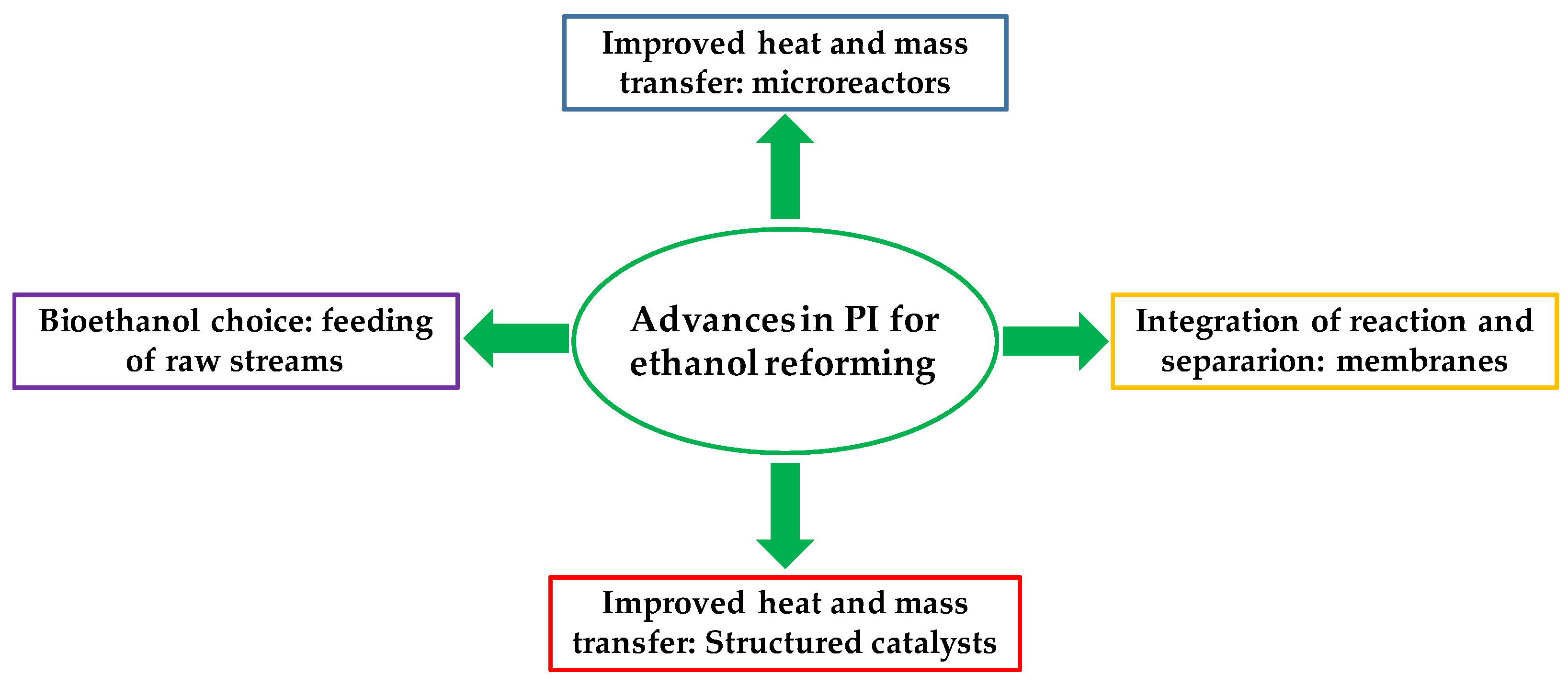
2.1.2. Structured Catalysts, Process Intensification, and Integration
2.1.3. Remarks
2.2. Process Intensification of WGS
2.2.1. Catalytic Formulations
2.2.2. Structured Catalysts, Process Intensification, and Integration
2.2.3. Remarks
2.3. CO2 Catalytic Hydrogenation to Hydrocarbons
2.3.1. CO2 to HC through Methanol Pathway
2.3.2. CO2 to HC through RWGS
2.3.3. Direct Conversion of CO2 to HC
- Catalytic formulation optimization through the investigation of new active metals or supports;
- Utilization of structured catalysts in different shapes and materials;
- Evaluation of innovative reactor configurations (membrane reactors);
- New technologies (cold plasma reactors).
Methanation over Structured Catalysts
Innovative Reactor Configurations
CO2 Methanation under NTP Process
Industrial Applications and Outlook
3. Conclusions
Author Contributions
Funding
Institutional Review Board Statement
Informed Consent Statement
Data Availability Statement
Conflicts of Interest
Abbreviation
| AM | Additive manufacturing |
| CCU | Carbon capture and utilization |
| CTLO | CO2 hydrogenation to lower olefins |
| DBD | Dielectric barrier discharges |
| DFT | Density functional theory |
| FTS | Fischer–Tropsch synthesis |
| GHSV | Gas hourly space velocity |
| HC | Hydrocarbons |
| H-SOD | Hydroxy sodalite |
| HTS | High-temperature shift |
| LTS | Low-temperature shift |
| MTO | Methanol conversion to olefins |
| NTP | Non-thermal plasma |
| OPEX | Operating expenses |
| ppi | Pores per inch |
| PPI | Process intensification |
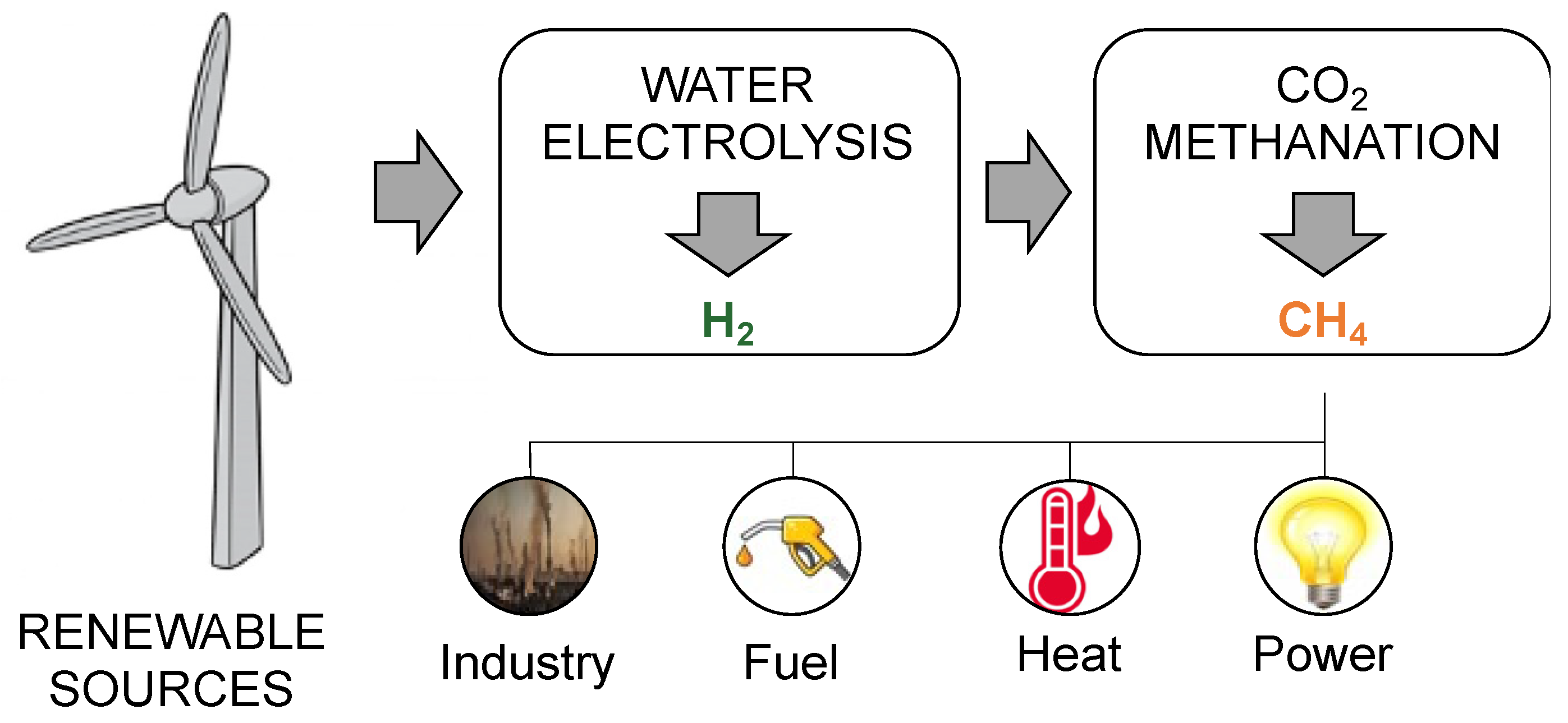
| PtM | Power-to-methane |
| RWGS | Reverse water–gas shift |
| SBA | Santa Barbara amorphous |
| SNG | Synthetic (or substitute) natural gas |
| WGS | Water–gas shift |
| WHSV | Weight hourly space velocity |
References
- The Paris Agreement. Available online: https://www.un.org/en/climatechange/paris-agreement (accessed on 18 February 2022).
- Soltani, S.M.; Lahiri, A.; Bahzad, H.; Clough, P.; Gorbounov, M.; Yan, Y. Sorption-enhanced Steam Methane Reforming for Combined CO2 Capture and Hydrogen Production: A State-of-the-Art Review. Carbon Capture Sci. Technol. 2021, 1, 100003. [Google Scholar] [CrossRef]
- Martino, M.; Ruocco, C.; Meloni, E.; Pullumbi, P.; Palma, V. Main Hydrogen Production Processes: An Overview. Catalysts 2021, 11, 547. [Google Scholar] [CrossRef]
- Safari, F.; Dincer, I. A review and comparative evaluation of thermochemical water splitting cycles for hydrogen production. Energy Convers. Manag. 2020, 205, 112182. [Google Scholar] [CrossRef]
- Yan, Y.; Thanganadar, D.; Clough, P.T.; Mukherjee, S.; Patchigolla, K.; Manovic, V.; Anthony, E.J. Process simulations of blue hydrogen production by upgraded sorption enhanced steam methane reforming (SE-SMR) processes. Energy Convers. Manag. 2020, 222, 113144. [Google Scholar] [CrossRef]
- van Renssen, S. The hydrogen solution? Nat. Clim. Chang. 2020, 10, 799–801. [Google Scholar] [CrossRef]
- European Commission. Europe’s Moment: Repair and Prepare for the Next Generation; European Commission: Bruxelles, Belgium, 2020.
- Anastas, P.T.; Warner, J.C. Green Chemistry: Theory and Practice; Oxford University Press: New York, NY, USA, 1998. [Google Scholar]
- Sheldon, R.A. Engineering a more sustainable world through catalysis and green chemistry. J. R. Soc. Interface 2016, 13, 20160087. [Google Scholar] [CrossRef] [PubMed] [Green Version]
- Huang, Y.; Wang, B.; Yuan, H.; Sun, Y.; Yang, D.; Cui, X. The catalytic dehydrogenation of ethanol by heterogeneous catalysts. Catal. Sci. Technol. 2021, 11, 1652–1664. [Google Scholar] [CrossRef]
- Constable, D.J.C. Green and sustainable chemistry—The case for a systems-based, interdisciplinary approach. iScience 2021, 24, 103489. [Google Scholar] [CrossRef] [PubMed]
- Kumar, A. Ethanol Decomposition and Dehydrogenation for Hydrogen Production: A Review of Heterogeneous Catalysts. Ind. Eng. Chem. Res. 2021, 60, 16561–16576. [Google Scholar]
- Sanchez, N.; Ruiz, R.Y.; Infante, N.; Cobo, M. Bioethanol Production from Cachaza as Hydrogen Feedstock: Effect of Ammonium Sulfate during Fermentation. Energies 2017, 10, 2112. [Google Scholar]
- Domínguez, M.; Taboada, E.; Molins, E.; Llorca, J. Co-Fe-Si Aerogel Catalytic Honeycombs for Low Temperature Ethanol Steam Reforming. Catalysts 2012, 2, 386–399. [Google Scholar]
- Song, J.H.; Yoo, S.; Yoo, J.; Park, S.; Gim, M.Y.; Kim, T.H.; Song, I.K. Hydrogen production by steam reforming of ethanol over Ni/Al2O3-La2O3 xerogel catalysts. Mol. Catal. 2017, 434, 123–133. [Google Scholar]
- Palma, V.; Ruocco, C.; Meloni, E.; Ricca, A. Influence of Catalytic Formulation and Operative Conditions on Coke Deposition over CeO2-SiO2 Based Catalysts for Ethanol Reforming. Energies 2017, 10, 1030. [Google Scholar]
- Pio, G.; Ruocco, C.; Palma, V.; Salzano, E. Detailed kinetic mechanism for the hydrogen production via the oxidative reforming of ethanol. Chem. Eng. Sci. 2021, 237, 116591. [Google Scholar]
- Palma, V.; Ruocco, C.; Cortese, M.; Martino, M. Bioalcohol Reforming: An Overview of the Recent Advances for the Enhancement of Catalyst Stability. Catalysts 2020, 10, 665. [Google Scholar]
- Palma, V.; Ruocco, C.; Ricca, A. Ceramic foams coated with PtNi/CeO2ZrO2 for bioethanol steam reforming. Int. J. Hydrog. Energy 2016, 41, 11526–11536. [Google Scholar]
- Sanchez, N.; Ruiz, R.; Hacker, V.; Cobo, M. Impact of bioethanol impurities on steam reforming for hydrogen production: A review. Int. J. Hydrog. Energy 2020, 45, 11923–11942. [Google Scholar]
- Cifuentes, B.; Gómez, J.; Sánchez, N.; Proaño, L.; Bustamante, F.; Cobo, M. Bioethanol steam reforming over monoliths washcoated with RhPt/CeO2–SiO2: The use of residual biomass to stably produce syngas. Int. J. Hydrog. Energy 2021, 46, 4007–4018. [Google Scholar]
- Sharma, Y.C.; Kumar, A.; Prasad, R.; Upadhyay, S.N. Ethanol steam reforming for hydrogen production: Latest and effective catalyst modification strategies to minimize carbonaceous deactivation. Renew. Sustain. Energy Rev. 2017, 74, 89–103. [Google Scholar]
- Ogo, S.; Sekine, Y. Recent progress in ethanol steam reforming using non-noble transition metal catalysts: A review. Fuel Process. Technol. 2020, 199, 106238. [Google Scholar]
- Ferreira, N.; Coronel, L.; Moreno, M.S.; Cornaglia, L.M.; Múnera, J.F. Active and stable Co catalysts supported on La-Si binary systems for H2 production through ethanol steam reforming. Fuel Process. Technol. 2021, 217, 106814. [Google Scholar]
- Liu, H.; Li, H.; Li, S. Ni-hydrocalumite derived catalysts for ethanol steam reforming on hydrogen production. Int. J. Hydrog. Energy 2021, 7, 141. [Google Scholar]
- Efimov, M.N.; Mironova, E.Y.; Vasilev, A.A.; Muratov, D.G.; Zhilyaeva, N.A.; Ozkan, S.Z.; Karpacheva, G.P. Comparison of bimetallic Co-Ru nanoparticles supported on highly porous activated carbonized polyacrylonitrile with monometallic ones in ethanol steam reforming. J. Environ. Chem. Eng. 2021, 9, 106429. [Google Scholar]
- Greluk, M.; Gac, W.; Rotko, M.; Słowik, G.; Turczyniak-Surdacka, S. Co/CeO2 and Ni/CeO2 catalysts for ethanol steam reforming: Effect of the cobalt/nickel dispersion on catalysts properties. J. Catal. 2021, 393, 159–178. [Google Scholar]
- Pizzolitto, C.; Menegazzo, F.; Ghedini, E.; Martínez Arias, A.; Cortés Corberán, V.; Signoretto, M. Microemulsion vs. Precipitation: Which Is the Best Synthesis of Nickel–Ceria Catalysts for Ethanol Steam Reforming? Processes 2021, 9, 77. [Google Scholar]
- Valecillos, J.; Iglesias-Vázquez, S.; Landa, L.; Remiro, A.; Bilbao, J.; Gayubo, A.G. Insights into the Reaction Routes for H2 Formation in the Ethanol Steam Reforming on a Catalyst Derived from NiAl2O4 Spinel. Energy Fuels 2021, 35, 17197–17211. [Google Scholar]
- Musso, M.; Cardozo, A.; Romero, M.; Faccio, R.; Segobia, D.; Apesteguía, C.; Bussi, J. High performance Ni-catalysts supported on rare-earth zirconates (La and Y) for hydrogen production through ethanol steam Characterization and assay. Catal. Today. in press. [CrossRef]
- Zhurka, M.D.; Lemonidou, A.A.; Kechagiopoulos, P.N. Elucidation of metal and support effects during ethanol steam reforming over Ni and Rh based catalysts supported on (CeO2)-ZrO2-La2O3. Catal. Today 2020, 368, 161–172. [Google Scholar]
- Martínez, A.H.; Lopez, E.; Cadús, L.E.; Agüero, F.N. Elucidation of the role of support in Rh/perovskite catalysts used in ethanol steam reforming reaction. Catal. Today 2021, 372, 59–69. [Google Scholar]
- Boudadi, K.; Bellifa, A.; Márquez-Álvarez, C.; Cortés Corberán, V. Nickel catalysts promoted with lanthanum for ethanol steam reforming: Influence of support and treatment on activity. Appl. Catal. A Gen. 2021, 619, 118141. [Google Scholar]
- Rajabi, Z.; Jones, L.; Martinelli, M.; Qian, D.; Cronauer, D.C.; Kropf, A.J.; Watson, C.D.; Jacobs, J. Influence of Cs Promoter on Ethanol Steam-Reforming Selectivity of Pt/m-ZrO2 Catalysts at Low Temperature. Catalysts 2021, 11, 1104. [Google Scholar]
- Martinelli, M.; Castro, J.D.; Alhraki, N.; Matamoros, M.E.; Kropf, A.J.; Cronauer, D.C.; Jacobs, G. Effect of sodium loading on Pt/ZrO2 during ethanol steam reforming. Appl. Catal. A Gen. 2021, 610, 117947. [Google Scholar]
- Martinelli, M.; Garcia, R.; Watson, C.D.; Cronauer, D.C.; Kropf, A.J.; Jacobs, G. Promoting the Selectivity of Pt/m-ZrO2 Ethanol Steam Reforming Catalysts with K and Rb Dopants. Nanomaterials 2021, 11, 2233. [Google Scholar] [PubMed]
- Matus, E.; Sukhova, O.; Ismagilov, I.; Kerzhentsev, M.; Stonkus, O.; Ismagilov, Z. Hydrogen Production through Autothermal Reforming of Ethanol: Enhancement of Ni Catalyst Performance via Promotion. Energies 2021, 14, 5176. [Google Scholar]
- An, X.; Feng, C.; Ren, J.; Shi, K.; Du, Y.; Xie, X.; Wu, X. Novel highly dispersed Ni-based oxides catalysts for ethanol steam reforming. J. Energy Inst. 2021, 99, 240–247. [Google Scholar]
- Ito, S.-. i Kameoka, S. Effect of strong metal-oxide interaction on low-temperature ethanol reforming over Fe-promoted Rh/SiO2 catalyst. Appl. Catal. A Gen. 2021, 617, 118113. [Google Scholar]
- Wu, Y.; Pei, C.; Tian, H.; Liu, T.; Zhang, X.; Chen, S.; Xiao, Q.; Wang, X.; Gong, J. Role of Fe Species of Ni-Based Catalysts for Efficient Low-Temperature Ethanol Steam Reforming. JACS Au 2021, 1, 1459–1470. [Google Scholar]
- Zanchet, D.; Santos, J.B.O.; Damyanova, S.; Gallo, J.M.R.; Bueno, J.M.C. Toward Understanding Metal-Catalyzed Ethanol Reforming. ACS Catal. 2015, 5, 3841–3863. [Google Scholar]
- Ni, M.; Leung, D.; Leung, M. A review on reforming bio-ethanol for hydorgen production. Int. J. Hydrog. Energy 2007, 32, 3238–3247. [Google Scholar] [CrossRef]
- Gu, T.; Zhu, W.; Yang, B. Ethanol steam reforming on Rh: Microkinetic analyses on the complex reaction network. Catal. Sci. Technol. 2021, 11, 7009–7017. [Google Scholar]
- Martinelli, M.; Watson, C.D.; Jacobs, G. Sodium doping of Pt/m-ZrO2 promotes C–C scission and decarboxylation during ethanol steam reforming. Int. J. Hydrog. Energy 2020, 45, 18490–18501. [Google Scholar]
- Hamryszak, A.; Madej-Lachowska, M.; Kulawska, M.; Ruggiero-MikoBajczyk, M.; Samson, K.; Zliwa, M. Investigation on binary copper-based catalysts used in the ethanol steam reforming process. React. Kinet. Mech. Catal. 2020, 130, 727–739. [Google Scholar]
- Palma, V.; Ruocco, C.; Castaldo, F.; Ricca, A.; Boettge, D. Ethanol steam reforming over bimetallic coated ceramic foams: Effect of reactor configuration and catalytic support. Int. J. Hydrog. Energy 2015, 40, 12650–12662. [Google Scholar]
- Belzunce, P.S.; Cadús, L.E.; Rodríguez, M.L. Cross-flow plate reactor for ethanol steam reforming: A theoretical study. Chem. Eng. Process.—Process. Intensif. 2021, 164, 108383. [Google Scholar]
- Escalante, Y.; Galetti, A.E.; Gómez, M.F.; Furlong, O.J.; Nazzarro, M.S.; Barroso, M.N.; Abello, M.C. Hydrogen production by ethanol steam reforming: A study of Co- and Ce-based catalysts over FeCrAlloy monoliths. Int. J. Hydrog. Energy 2020, 45, 20956–20969. [Google Scholar]
- Ruocco, C.; Palma, V.; Cortese, M.; Martino, M. Stability of bimetallic Ni/CeO2–SiO2 catalysts during fuel grade bioethanol reforming in a fluidized bed reactor. Renew. Energy 2022, 182, 913–922. [Google Scholar]
- Jia, H.; Xu, H.; Sheng, X.; Yang, X.; Shen, W.; Goldbach, A. High-temperature ethanol steam reforming in PdCu membrane reactor. J. Membr. Sci. 2020, 605, 118083. [Google Scholar]
- Eremeev, N.; Krasnov, A.; Bespalko, Y.; Bobrova, L.; Smorygo, O.; Sadykov, V. An Experimental Performance Study of a Catalytic Membrane Reactor for Ethanol Steam Reforming over a Metal Honeycomb Catalyst. Membranes 2021, 11, 790. [Google Scholar] [PubMed]
- Phung, T.K.; Le Minh Pham, T.; Nguyen, A.; Vu, K.; Giang, H.N.; Nguyen, T.; Cong Huynh, T.C.; Pham, D. Effect of Supports and Promoters on the Performance of Ni-Based Catalysts in Ethanol Steam Reforming. Chem. Eng. Technol. 2020, 42, 672–688. [Google Scholar] [CrossRef]
- Palma, V.; Ruocco, C.; Meloni, E.; Rivva, A. Oxidative reforming of ethanol over CeO2-SiO2 based catalysts in a fluidized bed reactor. Chem. Eng. Process. Process. Intensif. 2018, 124, 319–327. [Google Scholar] [CrossRef]
- Roldan, R. Technical and economic feasibility of adapting an industrial steam reforming unit for production of hydrogen from renewable ethanol. Int. J. Hydrog. Energy 2015, 40, 2035–2046. [Google Scholar] [CrossRef]
- Palma, V.; Ruocco, C.; Cortese, M.; Renda, S.; Meloni, E.; Festa, G.; Martino, M. Platinum Based Catalysts in the Water Gas Shift Reaction: Recent Advances. Metals 2020, 10, 866. [Google Scholar] [CrossRef]
- Chen, W.-H.; Chen, C.-Y. Water gas shift reaction for hydrogen production and carbon dioxide capture: A review. Appl. Energy 2020, 258, 114078. [Google Scholar] [CrossRef]
- Bang, G.; Moon, D.-K.; Kang, J.-H.; Han, Y.-J.; Kim, K.-M.; Lee, C.-H. High-purity hydrogen production via a water-gas-shift reaction in a palladium-copper catalytic membrane reactor integrated with pressure swing adsorption. Chem. Eng. J. 2021, 411, 128473. [Google Scholar] [CrossRef]
- Pal, D.; Chand, R.; Upadhyay, S.; Mishra, P.K. Performance of water gas shift reaction catalysts: A review. Renew. Sustain. Energy Rev. 2018, 93, 549–565. [Google Scholar]
- Zhu, M.; Wachs, I.E. Iron-Based Catalysts for the High-Temperature Water–Gas Shift (HT-WGS) Reaction: A Review. ACS Catal. 2015, 6, 722–732. [Google Scholar]
- Zhang, Z.; Chen, X.; Kang, J.; Yu, Z.; Tian, J.; Gong, Z.; Jia, A.; You, R.; Qian, K.; He, S.; et al. The active sites of Cu–ZnO catalysts for water gas shift and CO hydrogenation reactions. Nat. Commun. 2021, 12, 4331. [Google Scholar] [CrossRef] [PubMed]
- Dong, Z.; Liu, W.; Zhang, L.; Wang, S.; Luo, L. Structural Evolution of Cu/ZnO Catalysts during Water-Gas Shift Reaction: An In Situ Transmission Electron Microscopy Study. ACS Appl. Mater. Interfaces 2021, 13, 41707–41714. [Google Scholar] [CrossRef]
- Bian, Z.; Zhong, W.; Yu, Y.; Jiang, B.; Kawi, S. Cu/SiO2 derived from copper phyllosilicate for lowtemperature water-gas shift reaction: Role of Cu+ sites. Int. J. Hydrog. Energy 2020, 45, 27078–27088. [Google Scholar] [CrossRef]
- Salcedo, A.; Irigoyen, B. Unraveling the Origin of Ceria Activity in Water−Gas Shift by First Principles Microkinetic Modeling. J. Phys. Chem. C 2020, 124, 7823–7834. [Google Scholar] [CrossRef]
- Lee, Y.-H.; Kim, H.-M.; Jeong, C.-H.; Jeong, D.-W. Effects of precipitants on the catalytic performance of Cu/CeO2 catalysts for the water–gas shift reaction. Catal. Sci. Technol. 2021, 11, 6380. [Google Scholar] [CrossRef]
- Yu, W.-Z.; Wang, W.-W.; Ma, C.; Li, S.-Q.; Wu, K.; Zhu, J.-Z.; Zhao, H.-R.; Yan, C.-H.; Jia, C.-J. Very high loading oxidized copper supported on ceria to catalyze the water-gas shift reaction. J. Catal. 2021, 402, 83–93. [Google Scholar] [CrossRef]
- Ning, J.; Zhou, Y.; Shen, W. Atomically dispersed copper species on ceria for the low-temperature water-gas shift reaction. Sci. China Chem. 2021, 64, 1103–1110. [Google Scholar] [CrossRef]
- Liang, J.-X.; Lin, J.; Liu, J.; Wang, X.; Zhang, T.; Li, J. Dual Metal Active Sites in an Ir1/FeOx Single-Atom Catalyst: A Redox Mechanism for the Water-Gas Shift Reaction. Angew. Chem. Int. Ed. 2020, 59, 12868–12875. [Google Scholar] [CrossRef]
- Sun, L.; Xu, J.; Liu, X.; Qiao, B.; Li, L.; Ren, Y.; Wan, Q.; Lin, J.; Lin, S.; Wang, X.; et al. High-Efficiency Water Gas Shift Reaction Catalysis on α-MoC Promoted by Single-Atom Ir Species. ACS Catal. 2021, 11, 5942–5950. [Google Scholar] [CrossRef]
- Ariëns, M.I.; Chlan, V.; Novák, P.; van de Water, L.G.A.; Dugulan, A.I.; Brück, E.; Hensen, E.J.M. The role of chromium in iron-based high-temperature water-gas shift catalysts under industrial conditions. Appl. Catal. B-Environ. 2021, 297, 120465. [Google Scholar] [CrossRef]
- Yalcin, O.; Wachs, I.E.; Onal, I. Role of chromium in Cr–Fe oxide catalysts for high temperature water-gas shift reaction—A DFT study. Int. J. Hydrog. Energy 2021, 46, 17154–17162. [Google Scholar] [CrossRef]
- Ratnasamy, C.; Wagner, J.P. Water Gas Shift Catalysis. Catal. Rev. 2009, 51, 325–440. [Google Scholar] [CrossRef]
- Polo-Garzon, F.; Fung, V.; Nguyen, L.; Tang, Y.; Tao, F.; Cheng, Y.; Daemen, L.L.; Ramirez-Cuesta, R.-C.; Foo, G.S.; Zhu, M.; et al. Elucidation of the Reaction Mechanism for High-Temperature Water Gas Shift over an Industrial-Type Copper−Chromium−Iron Oxide Catalyst. J. Am. Chem. Soc. 2019, 141, 7990–7999. [Google Scholar] [CrossRef]
- Ariëns, M.I.; van de Water, L.G.A.; Dugulan, A.I.; Brück, E.; Hensen, E.J.M. Copper promotion of chromium-doped iron oxide water-gas shift catalysts under industrially relevant conditions. J. Catal. 2022, 405, 391–403. [Google Scholar] [CrossRef]
- Damma, D.; Welton, A.; Boolchand, P.; Dong, J.; Smirniotis, P.G. Ce/Cr and Ce/Co modified ferrite catalysts for high temperature water-gas shift reaction at elevated pressures. J. Catal. 2022, 405, 35–46. [Google Scholar] [CrossRef]
- Popovic, J.; Lindenthal, L.; Rameshan, R.; Ruh, T.; Nenning, A.; Löffler, S.; Opitz, A.K.; Rameshan, C. High Temperature Water Gas Shift Reactivity of Novel Perovskite Catalysts. Catalysts 2020, 10, 582. [Google Scholar] [CrossRef]
- Hongmanorom, P.; Ashok, J.; Das, S.; Dewangan, N.; Bian, Z.; Mitchell, G.; Xi, S.; Borgna, A.; Kawi, S. Zr–Ce-incorporated Ni/SBA-15 catalyst for high-temperature water gas shift reaction: Methane suppression by incorporated Zr and Ce. J. Catal. 2020, 387, 47–61. [Google Scholar] [CrossRef]
- Sadat Maboudi, N.; Meshkani, F.; Rezaei, M. Effect of mesoporous nanocrystalline supports on the performance of the Ni-Cu catalysts in the high-temperature water-gas shift reaction. J. Energy Inst. 2021, 96, 75–89. [Google Scholar] [CrossRef]
- Pei, Q.; Qiu, G.; Yu, Y.; Wang, J.; Chen Tan, K.; Guo, J.; Liu, L.; Cao, H.; He, T.; Chen, P. Fabrication of More Oxygen Vacancies and Depression of Encapsulation for Superior Catalysis in the Water−Gas Shift Reaction. J. Phys. Chem. Lett. 2021, 12, 10646–10653. [Google Scholar] [CrossRef] [PubMed]
- Pei, Q.; He, T.; Yu, Y.; Jing, Z.; Wang, J.; Chen Tan, K.; Guo, J.; Liu, L.; Cao, H.; Chen, P. Fabrication of oxygen vacancies through assembling an amorphous titanate overlayer on titanium oxide for a catalytic water–gas shift reaction. J. Mater. Chem. A 2021, 9, 2784. [Google Scholar] [CrossRef]
- Li, Y.-C.; Li, X.-S.; Zhu, B.; Zhu, A.-M. Boosting low-temperature water gas shift reaction over Au/TiO2 nanocatalyst activated by oxygen plasma. Chem. Eng. J. 2022, 430, 133013. [Google Scholar] [CrossRef]
- Shi, J.; Li, H.; Genest, A.; Zhao, W.; Qi, P.; Wang, T.; Rupprechter, G. High-performance water gas shift induced by asymmetric oxygen vacancies: Gold clusters supported by ceria-praseodymia mixed oxides. Appl. Catal. B-Environ. 2022, 301, 120789. [Google Scholar] [CrossRef]
- Meng, Y.; Chen, Y.; Zhou, X.; Pan, G.; Xia, S. Experimental and theoretical investigations into the activity and mechanism of the water-gas shift reaction catalyzed by Au nanoparticles supported on ZneAl/Cr/Fe layered double hydroxides. Int. J. Hydrog. Energy 2020, 45, 464–476. [Google Scholar] [CrossRef]
- Gabrovska, M.; Ivanov, I.; Nikolova, D.; Kovacheva, D.; Tabakova, T. Hydrogen production via water-gas shift reaction over gold supported on Ni-based layered double hydroxides. Int. J. Hydrog. Energy 2021, 46, 458–473. [Google Scholar] [CrossRef]
- Gabrovska, M.; Ivanov, I.; Nikolova, D.; Krstić, J.; Venezia, A.M.; Crişan, D.; Crişan, M.; Tenchev, K.; Idakiev, V.; Tabakova, T. Improved Water–Gas Shift Performance of Au/NiAl LDHs Nanostructured Catalysts via CeO2 Addition. Nanomaterials 2021, 11, 366. [Google Scholar] [CrossRef] [PubMed]
- Santos de Oliveira, C.; Teixeira Neto, E.; Odone Mazali, I. Stabilization and Au sintering prevention promoted by ZnO in CeOx–ZnO porous nanorods decorated with Au nanoparticles in the catalysis of the water-gas shift (WGS) reaction. J. Alloys Compd. 2021, 892, 162179. [Google Scholar] [CrossRef]
- Pastor-Pérez, L.; Ramos-Fernández, E.V.; Sepúlveda-Escribano, A. Effect of the CeO2 synthesis method on the behaviour of Pt/CeO2 catalysis for the water-gas shift reaction. Int. J. Hydrog. Energy 2019, 44, 21837–21846. [Google Scholar] [CrossRef]
- Li, Y.; Kottwitz, M.; Vincent, J.L.; Enright, M.J.; Liu, Z.; Zhang, L.; Huang, J.; Senanayake, S.D.; Yang, W.-C.D.; Crozier, P.A.; et al. Dynamic structure of active sites in ceria-supported Pt catalysts for the water gas shift reaction. Nat. Commun. 2021, 12, 914. [Google Scholar] [CrossRef] [PubMed]
- Gorlova, A.; Zadesenets, A.; Filatov, E.; Simonov, P.; Korenev, S.; Stonkus, O.; Sobyanin, V.; Snytnikov, P.; Potemkin, D. Pt-Fe nanoalloy: Structure evolution study and catalytic properties in water gas shift reaction. Mater. Res. Bull. 2022, 149, 111727. [Google Scholar] [CrossRef]
- Yuan, K.; Sun, X.-C.; Yin, H.-J.; Zhou, L.; Liu, H.-C.; Yan, C.-H.; Zhang, Y.W. Boosting the water gas shift reaction on Pt/CeO2-based nanocatalysts by compositional modification: Support doping versus bimetallic alloying. J. Energy Chem. 2022, 67, 241–249. [Google Scholar] [CrossRef]
- Palma, V.; Gallucci, F.; Pullumbi, P.; Ruocco, C.; Meloni, E.; Martino, M. Pt/Re/CeO2 Based Catalysts for CO-Water–Gas Shift Reaction: From Powders to Structured Catalyst. Catalysts 2020, 10, 564. [Google Scholar] [CrossRef]
- Palma, V.; Pisano, D.; Martino, M. Structured noble metal-based catalysts for the WGS process intensification. Int. J. Hydrog. Energy 2018, 43, 11745–11754. [Google Scholar] [CrossRef]
- García-Moncada, N.; Groppi, G.; Beretta, A.; Romero-Sarria, F.; Odriozola, J.A. Metal Micro-Monoliths for the Kinetic Study and the Intensification of the Water Gas Shift Reaction. Catalysts 2018, 8, 594. [Google Scholar] [CrossRef] [Green Version]
- Palma, V.; Pisano, D.; Martino, M. Comparative Study Between Aluminum Monolith and Foam as Carriers for The Intensification of The CO Water Gas Shift Process. Catalysts 2018, 8, 489. [Google Scholar] [CrossRef] [Green Version]
- Palma, V.; Goodall, R.; Thompson, A.; Ruocco, C.; Renda, S.; Leach, R.; Martino, M. Ceria-coated replicated aluminium sponges as catalysts for the CO-water gas shift process. Int. J. Hydrog. Energy 2021, 46, 12158–12168. [Google Scholar] [CrossRef]
- Meng, L.; Ovalle-Encinia, O.; Lin, J.Y.S. Catalyst-Free Ceramic−Carbonate Dual-Phase Membrane Reactors for High-Temperature Water Gas Shift: A Simulation Study. Ind. Eng. Chem. Res. 2021, 60, 3581–3588. [Google Scholar] [CrossRef]
- Sakakura, T.; Choi, J.-C.; Yasuda, H. Transformation of carbon dioxide. Chem. Rev. 2007, 107, 2365–2387. [Google Scholar] [PubMed]
- Song, Q.-W.; Zhou, Z.-H.; He, L.-N. Efficient, selective and sustainable catalysis of carbon dioxide. Green Chem. 2017, 19, 3707. [Google Scholar] [CrossRef]
- Hepburn, C.; Adlen, E.; Beddington, J.; Carter, E.A.; Fuss, S.; Mac Dowell, N.; Minx, J.C.; Smith, P.; Williams, C.K. The technological and economic prospects for CO2 utilization and removal. Nature 2019, 575, 87–97. [Google Scholar]
- Liang, J.; Wu, Q.; Huang, Y.B.; Cao, R. Reticular frameworks and their derived materials for CO2 conversion by thermo catalysis. Energy Chem. 2021, 3, 100064. [Google Scholar] [CrossRef]
- Shah, H.-U.R.; Ahmad, K.; Bashir, M.S.; Shah, S.S.A.; Najam, T.; Ashfaq, M. Metal organic frameworks for efficient catalytic conversion of CO2 and CO into applied products. Mol. Catal. 2022, 517, 112055. [Google Scholar] [CrossRef]
- Ali, S.S.; Tabassum, N. A review on CO2 hydrogenation to ethanol: Reaction mechanism and experimental studies. J. Environ. Chem. Eng. 2022, 10, 106962. [Google Scholar] [CrossRef]
- Grice, K.A. Carbon dioxide reduction with homogenous early transition metal complexes: Opportunities and challenges for developing CO2 catalysis. Coord. Chem. Rev. 2017, 336, 78–95. [Google Scholar]
- Sordakis, K.; Tang, C.; Vogt, L.K.; Junge, H.; Dyson, P.J.; Beller, M.; Laurenczy, G. Homogeneous catalysis for sustainable hydrogen storage in formic acid and alcohols. Chem. Rev. 2018, 118, 372–433. [Google Scholar]
- Yaashikaa, P.R.; Kumar, P.S.; Varjani, S.J.; Saravanan, A. A review on photochemical, biochemical and electrochemical transformation of CO2 into value-added products. J. CO2 Util. 2019, 33, 131–147. [Google Scholar]
- Ojelade, O.A.; Zaman, S.F. A review on CO2 hydrogenation to lower olefins: Understanding the structure-property relationships in heterogeneous catalytic systems. J. CO2 Util. 2021, 47, 101506. [Google Scholar] [CrossRef]
- De, S.; Dokania, A.; Ramirez, A.; Gascon, J. Advances in the design of heterogeneous catalysts and thermocatalytic processes for CO2 utilization. ACS Catal. 2020, 10, 14147–14185. [Google Scholar]
- Perazio, A.; Lowe, G.; Gobetto, R.; Bonin, J.; Robert, M. Light-driven catalytic conversion of CO2 with heterogenized molecular catalysts based on fourth period transition metals. Coord. Chem. Rev. 2021, 443, 214018. [Google Scholar] [CrossRef]
- Xie, B.; Lovell, E.; Hao Tan, T.; Jantarang, S.; Yu, M.; Scott, J.; Amal, R. Emerging material engineering strategies for amplifying photothermal heterogeneous CO2 catalysis. J. Energy Chem. 2021, 59, 108–125. [Google Scholar] [CrossRef]
- Chen, Z.; Wang, X.; Liu, L. Electrochemical Reduction of Carbon Dioxide to Value-Added Products: The Electrocatalyst and Microbial Electrosynthesis. Chem. Rec. 2019, 19, 1272–1282. [Google Scholar]
- Palma, V.; Cortese, M.; Renda, S.; Ruocco, C.; Martino, M.; Meloni, E. A review about the recent advances in selected nonthermal plasma assisted solid–gas phase chemical processes. Nanomaterials 2020, 10, 1596. [Google Scholar] [CrossRef]
- Garba, M.D.; Usman, M.; Khan, S.; Shehzad, F.; Galadima, A.; Fahad Ehsan, M.; Ghanem, A.S.; Humayun, M. CO2 towards fuels: A review of catalytic conversion of carbon dioxide to hydrocarbons. J. Environ. Chem. Eng. 2021, 9, 104756. [Google Scholar] [CrossRef]
- Li, Z.; Wang, J.; Qu, Y.; Liu, H.; Tang, C.; Miao, S.; Feng, Z.; An, H.; Li, C. Highly selective conversion of carbon dioxide to lower olefins. ACS Catal. 2017, 7, 8544–8548. [Google Scholar]
- Tian, H.; He, H.; Jiao, J.; Zha, F.; Guo, X.; Tang, X.; Chang, Y. Tandem catalysts composed of different morphology HZSM-5 and metal oxides for CO2 hydrogenation to aromatics. Fuel 2022, 314, 123119. [Google Scholar] [CrossRef]
- Zhou, X.; Su, T.; Jiang, Y.; Qin, Z.; Ji, H.; Guo, Z. CuO-Fe2O3-CeO2/HZSM-5 bifunctional catalyst hydrogenated CO2 for enhanced dimethyl ether synthesis. Chem. Eng. Sci. 2016, 153, 10–20. [Google Scholar]
- Wang, P.; Zha, F.; Yao, L.; Chang, Y. Synthesis of light olefins from CO2 hydrogenation over (CuO-ZnO)-kaolin/SAPO-34 molecular sieves. Appl. Clay Sci. 2018, 163, 249–256. [Google Scholar]
- Alvarez, A.; Bansode, A.; Urakawa, A.; Bavykina, A.V.; Wezendonk, T.A.; Makkee, M.; Gascon, J.; Kapteijn, F. Challenges in the greener production of Formates/Formic acid, methanol, and DME by heterogeneously catalyzed CO2 hydrogenation processes. Chem. Rev. 2017, 117, 9804–9838. [Google Scholar] [CrossRef] [PubMed]
- Yarulina, I.; De Wispelaere, K.; Bailleul, S.; Goetze, J.; Radersma, M.; Abou-Hamad, E.; Vollmer, I.; Goesten, M.; Mezari, B.; Hensen, E.J.M.; et al. Structure–performance descriptors and the role of Lewis acidity in the methanol-to-propylene process. Nat. Chem. 2018, 10, 804–812. [Google Scholar] [CrossRef] [Green Version]
- Chowdhury, A.D.; Houben, K.; Whiting, G.T.; Mokhtar, M.; Asiri, A.M.; Al-Thabaiti, S.A.; Basahel, S.N.; Baldus, M.; Weckhuysen, B.M. Initial carbon–Carbon bond formation during the early stages of the methanol-to-Olefin process proven by zeolite-trapped acetate and methyl acetate. Angew. Chem. Int. 2016, 55, 15840–15845. [Google Scholar] [CrossRef]
- Cai, D.; Wang, Q.; Jia, Z.; Ma, Y.; Cui, Y.; Muhammad, U.; Wang, Y.; Qian, W.; Wei, F. Equilibrium analysis of methylbenzene intermediates for a methanol-to-olefins process. Catal. Sci. Technol. 2016, 6, 1297–1301. [Google Scholar] [CrossRef]
- Yarulina, I.; Chowdhury, A.D.; Meirer, F.; Weckhuysen, B.M.; Gascon, J. Recent trends and fundamental insights in the methanol-to-hydrocarbons process. Nat. Catal. 2018, 1, 398–411. [Google Scholar] [CrossRef]
- Zhu, J.; Li, Y.; Muhammad, U.; Wang, D.; Wang, Y. Effect of alkene co-feed on the MTO reactions over SAPO-34. Chem. Eng. J. 2017, 316, 187–195. [Google Scholar] [CrossRef]
- Usman, M.; Zhu, J.; Chuiyang, K.; Arslan, M.T.; Khan, A.; Galadima, A.; Muraza, O.; Khan, I.; Helal, A.; Al-Maythalony, B.A.; et al. Propene adsorption-chemisorption behaviors on H-SAPO-34 zeolite catalysts at different temperatures. Catalysts 2019, 9, 919. [Google Scholar]
- Tada, S.; Kinoshita, H.; Ochiai, N.; Chokkalingam, A.; Hu, P.; Yamauchi, N.; Kobayashi, Y.; Iyoki, K. Search for solid acid catalysts aiming at the development of bifunctional tandem catalysts for the one-pass synthesis of lower olefins via CO2 hydrogenation. Int. J. Hydrog. Energy 2021, 46, 36721–36730. [Google Scholar] [CrossRef]
- Tong, M.; Chizema, L.G.; Chang, X.; Hondo, E.; Dai, L.; Zeng, Y.; Zeng, C.; Ahmad, H.; Yang, R.; Lu, P. Tandem catalysis over tailored ZnO-ZrO2/MnSAPO-34 composite catalyst for enhanced light olefins selectivity in CO2 hydrogenation. Microporous Mesoporous Mater. 2021, 320, 111105. [Google Scholar] [CrossRef]
- Mou, J.; Fan, X.; Liu, F.; Wang, X.; Zhao, T.; Chen, P.; Li, Z.; Yang, C.; Cao, J. CO2 hydrogenation to lower olefins over Mn2O3-ZnO/SAPO-34 tandem catalysts. Chem. Eng. J. 2021, 421, 129978. [Google Scholar] [CrossRef]
- Dorner, R.W.; Hardy, D.R.; Williams, F.W.; Willauer, H.D. Heterogeneous catalytic CO2 conversion to value-added hydrocarbons. Energy Environ. Sci. 2010, 3, 884–890. [Google Scholar] [CrossRef]
- Smith, Z.P.; Bachman, J.E.; Li, T.; Gludovatz, B.; Kusuma, V.A.; Xu, T.; Hopkinson, D.P.; Ritchie, R.O.; Long, J.R. Increasing M2(dobdc) loading in selective mixed-matrix membranes: A rubber toughening approach. Chem. Mater. 2018, 30, 1484–1495. [Google Scholar] [CrossRef]
- Batchu, R.; Galvita, V.V.; Alexopoulos, K.; Van der Borght, K.; Poelman, H.; Reyniers, M.-F.; Marin, G.B. Role of intermediates in reaction pathways from ethene to hydrocarbons over H-ZSM-5. Appl. Catal. A Gen. 2017, 538, 207–220. [Google Scholar] [CrossRef]
- Kotrel, S.; Knozinger, H.; Gates, B.C. The Haag–Dessau mechanism of protolytic cracking of alkanes. Microporous Mesoporous Mater. 2000, 35–36, 11–20. [Google Scholar] [CrossRef]
- Sartipi, S.; Makkee, M.; Kapteijn, F.; Gascon, J. Catalysis engineering of bifunctional solids for the one-step synthesis of liquid fuels from syngas: A review. Catal. Sci. Technol. 2014, 4, 893–907. [Google Scholar] [CrossRef] [Green Version]
- Hagen, A.; Roessner, F. Ethane to aromatic hydrocarbons: Past, present, Future. Catal. Rev. 2000, 42, 403–437. [Google Scholar] [CrossRef]
- Joshi, Y.V.; Thomson, K.T. Brønsted Acid Catalyzed Cyclization of C7 and C8 Dienes in HZSM-5: A Hybrid QM/MM Study and Comparison with C6 Diene Cyclization. J. Phys. Chem. C 2008, 112, 12825–12833. [Google Scholar] [CrossRef]
- Tabor, E.; Bernauer, M.; Wichterlova, B.; Dedecek, J. Enhancement of propene oligomerization and aromatization by proximate protons in zeolites; FTIR study of the reaction pathway in ZSM-5. Catal. Sci. Technol. 2019, 9, 4262–4275. [Google Scholar] [CrossRef]
- Zhang, Z.; Huang, G.; Tang, X.; Yin, H.; Kang, J.; Zhang, Q.; Wang, Y. Zn and Na promoted Fe catalysts for sustainable production of high-valued olefins by CO2 hydrogenation. Fuel 2022, 309, 122105. [Google Scholar] [CrossRef]
- Sun, Z.; Chen, X.; Lu, F.; Zhou, L.; Zhang, Y. Effect of Rb promoter on Fe3O4 microsphere catalyst for CO2 hydrogenation to light olefins. Catal. Commun. 2022, 162, 106387. [Google Scholar] [CrossRef]
- Zhang, Z.; Liu, Y.; Jia, L.; Sun, C.; Chen, B.; Liu, R.; Tan, Y.; Tu, W. Effects of the reducing gas atmosphere on performance of FeCeNa catalyst for the hydrogenation of CO2 to olefins. Chem. Eng. J. 2022, 428, 131388. [Google Scholar] [CrossRef]
- Lino, A.V.P.; Assaf, E.M.; Assaf, J.M. Production of light hydrocarbons at atmospheric pressure from CO2 hydrogenation using CexZr(1-x)O2 iron-based catalysts. J. CO2 Util. 2022, 55, 101805. [Google Scholar] [CrossRef]
- Al-Zakwani, S.S.; Maroufmashat, A.; Mazouz, A.; Fowler, M.; Elkamel, A. Allocation of Ontario’s Surplus Electricity to Different Power-to-Gas Applications. Energies 2019, 12, 2675. [Google Scholar]
- Castellani, B.; Gambelli, A.M.; Morini, E.; Nastasi, B.; Presciutti, A.; Filipponi, M.; Nicolini, A.; Rossi, F. Experimental Investigation on CO2 Methanation Process for Solar Energy Storage Compared to CO2-Based Methanol Synthesis. Energies 2017, 10, 855. [Google Scholar] [CrossRef]
- Sterner, M.; Specht, M. Power-to-Gas and Power-to-X–The Hystory and Results of Developing a New Storage Concept. Energies 2021, 14, 6594. [Google Scholar]
- Garbarino, G.; Pugliese, F.; Cavattoni, T.; Busca, G.; Costamagna, P. A Study on CO2 Methanation and Steam Methane Reforming over Commercial Ni/Calcium Aluminate Catalysts. Energies 2020, 13, 2792. [Google Scholar] [CrossRef]
- Rozzi, E.; Minuto, F.D.; Lanzini, A.; Leone, P. Green Synthetic Fuels: Renewable Routes for the Conversion of Non-Fossil Feedstocks into Gaseous Fuels and Their End Uses. Energies 2020, 13, 420. [Google Scholar] [CrossRef] [Green Version]
- Cao, H.; Wang, W.; Cui, T.; Wang, H.; Zhu, G.; Ren, X. Enhancing CO2 Hydrogenation to Methane by Ni-Based Catalyst with V Species Using 3D-mesoporous KIT-6 as Support. Energies 2020, 13, 2235. [Google Scholar] [CrossRef]
- Tsiotsias, A.I.; Charisiou, N.D.; Yentekakis, I.V.; Goula, M.A. Bimetallic Ni-based catalysts for CO2 methanation: A review. Nanomaterials 2021, 11, 28. [Google Scholar] [CrossRef]
- Renda, S.; Ricca, A.; Palma, V. Study of the effect of noble metal promotion in Ni-based catalyst for the Sabatier reaction. Int. J. Hydrog. Energy 2020, 46, 12117–12127. [Google Scholar] [CrossRef]
- Ghaib, K.; Nitz, K.; Ben-Fares, F.Z. Chemical methanation of CO2: A review. ChemBioEng Rev. 2016, 3, 266–275. [Google Scholar] [CrossRef]
- Di Stasi, C.; Renda, S.; Greco, G.; González, B.; Palma, V.; Manyà, J.J. Wheat-straw-derived activated biochar as a renewable support of Ni-CeO2 catalysts for CO2 methanation. Sustainability 2021, 13, 8939. [Google Scholar] [CrossRef]
- Frontera, P.; Macario, A.; Ferraro, M.; Antonucci, P.L. Supported catalysts for CO2 methanation: A review. Catalysts 2017, 7, 59. [Google Scholar] [CrossRef]
- Lee, W.J.; Li, C.; Prajitno, H.; Yoo, J.; Patel, J.; Yang, Y.; Lim, S. Recent trend in thermal catalytic low temperature CO2 methanation: A critical review. Catal. Today 2021, 368, 2–19. [Google Scholar] [CrossRef]
- Ashok, J.; Pati, S.; Hongmanorom, P.; Tianxi, Z.; Junmei, C.; Kawi, S. A review of recent catalyst advances in CO2 methanation processes. Catal. Today 2020, 356, 471–489. [Google Scholar] [CrossRef]
- Fan, W.K.; Tahir, M. Recent trends in developments of active metals and heterogenous materials for catalytic CO2 hydrogenation to renewable methane: A review. J. Environ. Chem. Eng. 2021, 9, 105460. [Google Scholar]
- Huynh, H.L.; Yu, Z. CO2 Methanation on Hydrotalcite-Derived Catalysts and Structured Reactors: A Review. Energy Technol. 2020, 8, 1901475. [Google Scholar] [CrossRef] [Green Version]
- Huynh, H.L.; Tucho, W.M.; Shen, Q.; Yu, Z. Bed packing configuration and hot-spot utilization for low-temperature CO2 methanation on monolithic reactor. Chem. Eng. J. 2022, 428, 131106. [Google Scholar]
- García-Moncada, N.; Navarro, J.C.; Odriozola, J.A.; Lefferts, L.; Faria, J.A. Enhanced catalytic activity and stability of nanoshaped Ni/CeO2 for CO2 methanation in micro-monoliths. Catal. Today 2022, 383, 205–215. [Google Scholar] [CrossRef]
- Navarro, J.C.; Centeno, M.A.; Laguna, O.H.; Odriozola, J.A. Ru–Ni/MgAl2O4 structured catalyst for CO2 methanation. Renew. Energy 2020, 161, 120–132. [Google Scholar] [CrossRef]
- Ratchahat, S.; Sudoh, M.; Suzuki, Y.; Kawasaki, W.; Watanabe, R.; Fukuhara, C. Development of a powerful CO2 methanation process using a structured Ni/CeO2 catalyst. J. CO2 Util. 2018, 24, 210–219. [Google Scholar] [CrossRef]
- Vita, A.; Italiano, C.; Pino, L.; Laganà, M.; Ferraro, M.; Antonucci, V. High-temperature CO2 methanation over structured Ni/GDC catalysts: Performance and scale-up for Power-to-Gas application. Fuel Process. Technol. 2020, 202, 106365. [Google Scholar] [CrossRef]
- Ricca, A.; Truda, L.; Palma, V. Study of the role of chemical support and structured carrier on the CO2 methanation reaction. Chem. Eng. J. 2019, 377, 120461. [Google Scholar] [CrossRef]
- Cimino, S.; Cepollaro, E.M.; Lisi, L.; Fasolin, S.; Musiani, M.; Vázquez-Gómez, L. Ru/ce/ni metal foams as structured catalysts for the methanation of CO2. Catalysts 2021, 11, 13. [Google Scholar] [CrossRef]
- Italiano, C.; Ferrante, G.D.; Pino, L.; Laganà, M.; Ferrato, M.; Antonucci, V.; Vita, A. Silicon carbide and alumina open-cell foams activated by Ni/CeO2-ZrO2 catalyst for CO2 methanation in a heat-exchanger reactor. Chem. Eng. J. 2022, 434, 134685. [Google Scholar] [CrossRef]
- Sánchez, A.; Milt, V.G.; Miró, E.E.; Güttel, R. Impact of heat transport properties and configuration of ceramic fibrous catalyst structures for CO2 methanation: A simulation study. J. Environ. Chem. Eng. 2022, 10, 107148. [Google Scholar] [CrossRef]
- Danaci, S.; Protasova, L.; Lefevere, J.; Bedel, L.; Guilet, R.; Marty, P. Efficient CO2 methanation over Ni/Al2O3 coated structured catalysts. Catal. Today 2016, 273, 234–243. [Google Scholar] [CrossRef]
- Danaci, S.; Protasova, L.; Snijkers, F.; Bouwen, W.; Bengaouer, A.; Marty, P. Innovative 3D-manufacture of structured copper supports post-coated with catalytic material for CO2 methanation. Chem. Eng. Process.—Process Intensif. 2018, 127, 168–177. [Google Scholar] [CrossRef]
- Fuentes, I.; Gracia, F. Fluid dynamic analytical model of CO2 methanation in a microreactor with potential application in Power-to-Gas technology. Chem. Eng. Sci. 2022, 251, 117465, in press. [Google Scholar] [CrossRef]
- Catarina Faria, A.; Miguel, C.V.; Madeira, L.M. Thermodynamic analysis of the CO2 methanation reaction with in situ water removal for biogas upgrading. J. CO2 Util. 2018, 26, 271–280. [Google Scholar] [CrossRef]
- Ohya, H.; Fun, J.; Kawamura, H.; Itoh, K.; Ohashi, H.; Aihara, M.; Tanisho, S.; Negishi, Y. Methanation of carbon dioxide by using membrane reactor integrated with water vapor permselective membrane and its analysis. J. Memb. Sci. 1997, 131, 237–247. [Google Scholar] [CrossRef]
- Catarina Faria, A.; Miguel, C.V.; Rodrigues, A.E.; Madeira, L.M. Modeling and Simulation of a Steam-Selective Membrane Reactor for Enhanced CO2 Methanation. Ind. Eng. Chem. Res. 2020, 59, 16170–16184. [Google Scholar] [CrossRef]
- Liu, Z.; Bian, Z.; Wang, Z.; Jiang, B. A CFD study on the performance of CO2 methanation in a water-permeable membrane reactor system. React. Chem. Eng. 2022, 7, 450–459. [Google Scholar] [CrossRef]
- Miyamoto, M.; Hayakawa, R.; Makino, Y.; Oumi, Y.; Uemiya, S.; Asanuma, M. CO2 methanation combined with NH3 decomposition by in situ H2 separation using a Pd membrane reactor. Int. J. Hydrog. Energy 2014, 39, 10154–10160. [Google Scholar] [CrossRef]
- Bian, Z.; Xia, H.; Zhong, W.; Jiang, B.; Yu, Y.; Wang, Z.; Yu, K. CFD simulation on hydrogen-membrane reactor integrating cyclohexane dehydrogenation and CO2 methanation reactions: A conceptual study. Energy Convers. Manag. 2021, 235, 113989. [Google Scholar] [CrossRef]
- Bacariza, M.C.; Biset-Peiró, M.; Graça, I.; Guilera, J.; Morante, J.; Lopes, J.M.; Andreu, T.; Henriques, C. DBD plasma-assisted CO2 methanation using zeolite-based catalysts: Structure composition-reactivity approach and effect of Ce as promoter. J. CO2 Util. 2018, 26, 202–211. [Google Scholar] [CrossRef]
- Ahmad, F.; Lovell, E.C.; Masood, H.; Cullen, P.J.; Ostrikov, K.K.; Scott, J.A.; Amal, R. Low-Temperature CO2 Methanation: Synergistic Effects in Plasma-Ni Hybrid Catalytic System. ACS Sustain. Chem. Eng. 2020, 8, 1888–1898. [Google Scholar] [CrossRef]
- Wierzbicki, D.; Moreno, M.V.; Ognier, S.; Motak, M.; Grzybek, T.; Da Costa, P.; Gálvez, M.E. Ni-Fe layered double hydroxide derived catalysts for non-plasma and DBD plasma-assisted CO2 methanation. Int. J. Hydrog. Energy 2020, 45, 10423–10432. [Google Scholar] [CrossRef]
- Biset-Peiró, M.; Mey, R.; Guilera, J.; Andreu, T. Adiabatic plasma-catalytic reactor configuration: Energy efficiency enhancement by plasma and thermal synergies on CO2 methanation. Chem. Eng. J. 2020, 393, 124786. [Google Scholar] [CrossRef]
- Gao, Y.; Dou, L.; Zhang, S.; Zong, L.; Pan, J.; Hu, X.; Sun, H.; Ostrikov, K.; Shao, T. Coupling bimetallic Ni-Fe catalysts and nanosecond pulsed plasma for synergistic low-temperature CO2 methanation. Chem. Eng. J. 2021, 420, 127693. [Google Scholar] [CrossRef]
- Gao, W.; Chen, H. Mechanochemical Synthesis of Ni−Y/CeO2 Catalyst for Nonthermal Plasma Catalytic CO2 Methanation. Ind. Eng. Chem. Res. 2022, 61, 1666–1674. [Google Scholar] [CrossRef]


| Catalyst | (D a, %) or (d b,nm) | Experimental Results | Strategy | Ref. |
|---|---|---|---|---|
| Co/La2O3–SiO2 | dCo = 6 nm | X c = 100% for 25 h T = 500 °C f.r. d = 5 W/F e= 3.3 102 g h L−1 CFR f = 1.4·10−3 gc·gcat−1·h−1 | Metal loading: enhancement of catalyst surface area upon the increase in metal content | [24,25] |
| Ni/hydrocalumite | dNi = 28 nm | X = 99% T = 550–700 °C f.r. = 6 | Metal loading: enhancement of catalyst surface area upon the increase in metal content | |
| Co–Ru/carbon | dCo-Ru = 12 nm | X = 100% for 16 h T = 550 °C f.r. = 3 GHSV g = 89 h−1 | Preparation method: pyrolysis of polyacrylonitrile | [26] |
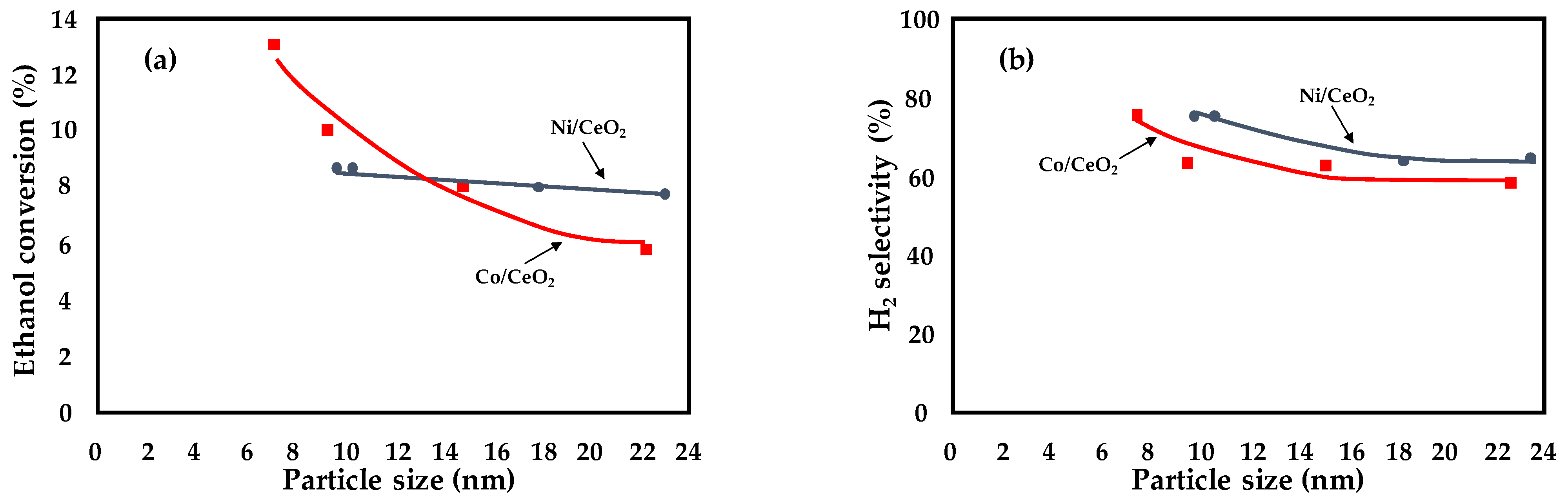
| Ni/CeO2 Co/CeO2 | dCo/Ni = 10–22 nm | X = 8% T = 420 °C f.r = 12 GHSV = 1,286,000 mL h−1·g−1 | Preparation method: use of acetates as salt precursors; addition of citric acid to nitrate salt precursors | [27] |
| Ni/CeO2 | dNi = 25 nm | X = 100% T = 500 °C f.r. = 6 W/F = 0.12 gcat·h·mol−1 | Preparation method: impregnation instead of microemulsion | [28] |
| Ni/Al2O3 | dNi = 50 nm | X = 100% for 48 h T = 600 °C f.r. = 3 Space time = 0.2 CFR = 0.4 gc·gcat−1·h- | Preparation method: coprecipitation instead of impregnation | [29] |
| Ni/Me2Zr2O7 | dNi = 15 nm | X = 100% for 50 h T = 650 °C f.r. = 9 GHSV = 41,000 h−1 CFR = 9 10−4 gc·gcat−1·h−1 | Promoter: yttria addition with a Me/Zr molar ratio of 1:1 | [30] |
| Rh/ZrO2–La2O3 | DRh = 29% | X = 95% for 4 h T = 500 °C f.r. = 6 W/F = 358.57 g·s·gethanol−1 CFR = 2.5 10−4 gc·gcat−1·h−1 | Promoter: addition of CeO2 to the support | [31,32] |
| Rh/LaAl2O3 | - | X = 100% for 24 h T = 500 °C f.r. = 5 WHSV= 10−3 mL·mgcat−1 min−1 CFR = 5.5 10−4 gc·gcat−1·h−1 | Promoter: addition of CeO2 to the support | |
| Ni/Al2O3 | dNi = 20 nm | X = 50% after 6 h T = 500 °C f.r. = 6 CFR = 1.7 10−2 gc·gcat−1·h−1 | Promoter: addition of La2O3 to the support | [33] |
| Ni/Ce0.8La0.201.9 | dNi = 15 nm | X = 100% T = 400 °C f.r. = 4 | Promoter: Re addition to Ni instead of Pt, Pd or Rh | [37] |
| NiAl layered double hydroxides | dNi = 11 nm | X = 100% for 18 h T = 500 °C f.r. = 3 | Promoter: Cu and Mg addition (molar ratio Mg2+/(Ni2++Cu2+) = 2/1) | [38] |
| Ni/MgAl2O4 catalyst | dNi = 8 nm | X = 100% for 3 h T = 400 °C f.r. = 8 GHSV = 59,146 mL·g−1·h−1 | Promoter: Fe addition with an Fe/Ni molar ratio of 1:1 | [40] |
| Reaction | Equation | Remarks |
|---|---|---|
| Sufficient steam supply | C2H5OH + 3H2O ↔ 6H2 + 2CO2 | Ideal pathway, the highest hydrogen production |
| Insufficient steam supply | C2H5OH + H2O ↔ 4H2 + 2CO C2H5OH + 2H2 ↔ 2CH4 + H2O | Undesirable products, lower hydrogen production |
| Dehydrogenation | C2H5OH ↔ C2H4O + H2 | Reaction pathways for hydrogen production in practice |
| Acetaldehyde decomposition | C2H4O ↔ CH4 + CO | |
| Acetaldehyde steam reforming | C2H4O + H2O ↔ 3H2 + 2CO | |
| Dehydration | C2H5OH ↔ C2H4 + H2O | Undesired pathway, main source of coke formation |
| Coke formation | C2H4→polymeric deposits (coke) | |
| Decomposition | C2H5OH ↔ CO + H2 + CH4 | Coke formation, low hydrogen production |
| 2C2H5OH ↔ C3H6O + CO + 3H2 | ||
| C2H5OH↔0.5CO2 + 1.5CH4 | ||
| Reaction of decomposition products | ||
| Methanation | CO + 3H2 ↔ CH4 + H2O | |
| CO2 + 4H2 ↔ CH4 + 2H2O | ||
| Methane decomposition | CH4 → 2H2 + C | |
| Boudouard reaction | 2CO → CO2 + C | |
| Water–gas shift | CO + H2O ↔ CO2 + H2 | Reduce coke formation, enhance hydrogen production |
| Selected Catalyst | Reaction Conditions | CO Conversion; Time on Stream | Reference |
|---|---|---|---|
| 9%ZnO/c-Cu-34 | CO/H2O/Ar = 5/10/85; 200 °C; GHSV = 3600 h−1 | XCO ≈ 80% | [60] |
| Cu/SiO2 | CO/H2O/He = 5/5/40; 250 °C; GHSV = 30,000 h−1 | XCO ≈ 27%; 24 h | [62] |
| Cu/CeO2 | CO/CO2/CH4/H2/H2O/N2 = 9/10/1/60/60/20; 360 °C; GHSV = 50,102 h−1 | XCO ≈ 60%; 110 h | [64] |
| 20CuCe-NS | CO/H2O/N2 = 2/10/88; 250 °C; GHSV = 42,000 h−1 | XCO ≈ 92%; 73 h | [65] |
| Cu/CeO2 | CO/H2O/N2 = 1/3/96; 200 °C; GHSV = 40,000 h−1 | XCO ≈ 30%; 12 h | [66] |
| Ir/ɑ-MoC | CO/H2O/He = 2/10/88; 150 °C; GHSV = 18,000 h−1 | XCO ≈ 100% | [68] |
| Cr2O3/ɑ-Fe2O3 | H2/CO/CO2/N2/H2O = 37/9/4/17/33; 450 °C | XCO ≈ 75%; 90 h | [69] |
| α-Fe2O3/Cr2O3/CuO | H2/CO/CO2/N2/H2O = 37/9/4/17/33; 450 °C; 25 bar | XCO ≈ 75%; 90 h | [73] |
| FeCeCoOx | CO/H2O = 2/7; 500 °C; 20 bar; GHSV = 30,000 h−1 | XCO ≈ 90%; 150 h | [74] |
| Ni/Zr–Ce-SBA-15 | CO/H2O/He = 5/25/70; 400 °C; GHSV = 40,000 h−1 | XCO ≈ 98%; 70 h | [76] |
| 7Ni-7.5Cu/CeO2–Al2O3 | H2/CO/CO2/H2O = 6/3/1/6; 400 °C; GHSV = 30,000 h−1 | XCO ≈ 35%; 20 h | [77] |
| Ni/TiO2(A)-Na | CO/H2O/He = 5/20/75; 350 °C, GHSV = 60,000 mL·g−1·h−1 | XCO ≈ 42%; 8 h | [78] |
| Ni–Na-R350 | CO/H2O/He = 5/20/75; 350 °C; GHSV = 20,000 mL·g−1·h−1 | XCO ≈ 98% | [79] |
| Au/TiO2 | CO/H2O/He = 5/10/85; 150 °C; GHSV = 12,000 mL·g−1·h−1 | XCO ≈ 70%; 4 h | [80] |
| Au/Ce4Pr1OX | CO/H2O/N2 = 2/10/88; 300 °C; GHSV = 54,000 mL·g−1·h−1 | XCO ≈ 70%; 50 h | [81] |
| Au/ZnCr-LDHs | CO/H2O/Ar = 3/15/82; 300 °C; GHSV = 90,000 mL·g−1·h−1 | XCO ≈ 75%; 50 h | [82] |
| Au/NiMgAl | CO/H2O/Ar = 3.76/25.01/71.23; 260 °C; GHSV = 4000 h−1 | XCO ≈ 95% | [83] |
| Au/eCeNiAl | CO/H2O/Ar = 3.76/25.01/71.23; 220 °C; GHSV = 4000 h−1 | XCO ≈ 99% | [84] |
| Pt/CeO2-urea | CO/H2O/H2/CO2/He = 7/30/50/9/4; 380 °C; GHSV = 40,000 mL·g−1·h−1 | XCO ≈ 70% | [86] |
| Pt0.5Fe0.5/SiO2 | CO/CO2/H2O/H2 = 10/15/30/45; 350 °C; GHSV = 75,000 mL·g−1·h−1 | XCO ≈ 55% | [88] |
| PtRe/CeO2/Al-foam | H2/CO2/CO/H2O/CH4 = 37.41/9.31/9.31/42.19/1.37; 330 °C; τ = 53 ms | XCO ≈ 85% | [90] |
| 1Pt/1Re/CeZrO4/Al2O3/Al-foam10_10 | CO/CO2/H2O/H2/N2 = 5.36/5.36/26.56/42.72/20; 300 °C; GHSV = 20,000 h−1 | XCO ≈ 90% | [91] |
| PtCeAl-ZrEuMo/monolith | CO/CO2/H2O/H2 = 9/11/30/50; 330 °C; GHSV = 80,000 mL·g−1·h−1 | XCO ≈ 25%; 70 h | [92] |
| Pt/CeO2/Al-monolith | CO/H2O/N2 = 8/30/62; 255 °C; τc = 360 ms | XCO ≈ 99% | [93] |
| Pt/CeO2/Al-sponge | CO/H2O/N2 = 8/30/62; 320 °C; τc = 38 ms | XCO ≈ 55%; 35 h | [94] |
| Object of the Study | Main Findings | Ref. |
|---|---|---|
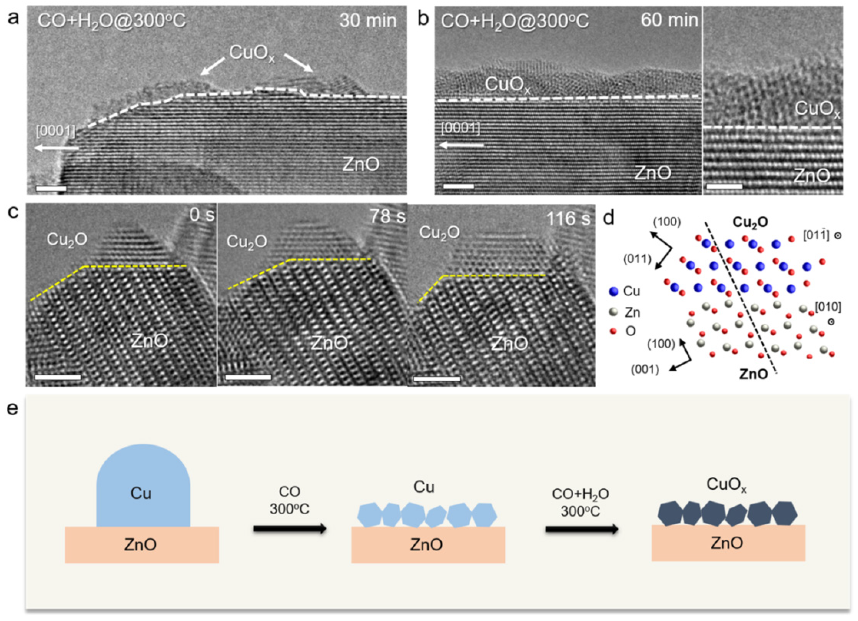
| The structure of LTS catalysts | ZnO–Cu catalysts undergo in situ Cu restructuring during the WGS reaction, forming a mixed phase of CuOx–ZnOx with an empty shell structure. | [60-.61] |
| Alternative LTS catalytic systems | Cu-based catalysts supported on various oxides (SiO2, CeO2) are proposed. α-MoC modified by Ir1 single-atom catalyst shows a CO conversion of ∼100% at 150 °C. Ir is a promoter that affects the electronic structure of active Mo sites. | [62,68] |
| The role of chromium in HTS catalysts | Chromium is a structural promoter, and its incorporation in the octahedral sites of magnetite prevents the reduction of Fe3+ ions. Doping with a metal may affect the Fe3+/Fe2+ ratio on the ferrite surface. | [69,70,71,72,73,74] |
| Alternative HTS catalytic systems | Ni-based catalysts are the most interesting alternative to conventional HTS catalysts. These include both perovskite-type oxides and those supported on various oxides such as SBA, ZrO2, CeO2, and TiO2. | [75,76,77,78,79] |
| Au-based catalyst activation and stability | O2 plasma allows control of the Au nanoparticle size and modulation of the electronic structure at interfaces. Double-layered support and nanorods allow better dispersion of Au nanoparticles. | [80,81,82,83,84,85] |
| Pt-based catalyst activity | The metal–support interaction depends on the morphology of the support. The redox path at the dynamic perimeter Pt0-O vacancy-Ce3+ site is preferred. The bimetallic PtFe system shows enhanced activity both as alloy and when supported on ceria. | [86,87,88,89] |
| Comparison between powder and conductive structured catalysts | The improved management of the reaction heat on the conductive structured catalyst is beneficial for kinetics and CO conversion. | [90,91] |
| Pt-based washcoated microchannel metal structure | The reaction order is around zero for carbon monoxide, negative for hydrogen, and 0.36 for water. | [92] |
| Structured catalyst reactor configuration | Foam structures provide improved heat and mass transfer compared to the honeycomb monolith structure. | [93,94] |
| Ceramic–carbonate dual-phase membrane reactor | Hydrogen purity > 90%, CO2 capture ratio > 98%. | [95] |
| Integrated Pd–Cu membrane reactor | The conversion rate increases by 10.0–16.7%, and Co conversion increases from 85.4 to 94.8%. | [57] |
| Catalyst | Reaction Conditions | CO2 Conversion | Reference |
|---|---|---|---|
| ZnZr7O(500)-sheetZ5 | 360 °C; 3 MPa; 4800 mL⋅g−1 h−1 | 17.2% | [113] |
| ZnZr7O(500)-hollowZ5 | 360 °C; 3 MPa; 4800 mL⋅g−1 h−1 | 14.1% | [113] |
| ZnZr7O(500)-sphericalZ5 | 360 °C; 3 MPa; 4800 mL⋅g−1 h−1 | 10.8% | [113] |
| ZnZr7O(500)-chainZ5 | 360 °C; 3 MPa; 4800 mL⋅g−1 h−1 | 13.5% | [113] |
| In2O3-sheetZ5 | 360 °C; 3 MPa; 4800 mL⋅g−1 h−1 | 24.9% | [113] |
| Cu–ZnO–Al2O3-sheetZ5 | 360 °C; 3 MPa; 4800 mL⋅g−1 h−1 | 34.5% | [113] |
| ZnZrOx + MOR | 375 °C; 10 bar; 2100 mL⋅g−1 h−1 | 20.9% | [123] |
| ZnZrOx + SAPO-34 | 375 °C; 10 bar; 2100 mL⋅g−1 h−1 | 17.9% | [123] |
| ZnZrOx + ERI | 375 °C; 10 bar; 2100 mL⋅g−1 h−1 | 23.6% | [123] |
| ZnZrOx + MFI | 375 °C; 10 bar; 2100 mL⋅g−1 h−1 | 22.0% | [123] |
| 13%ZnO–ZrO2 | 380 °C; 2.0 MPa; 4800 h−1; ratio of ZnO–ZrO2 to zeolite = 1 | 15.9% | [124] |
| 13%ZnO–ZrO2/ SAPO-34 | 380 °C; 2.0 MPa; 4800 h−1; ratio of ZnO–ZrO2 to zeolite = 1 | 17.3% | [124] |
| 13%ZnO–ZrO2/ Mn0.1SAPO- 34 | 380 °C; 2.0 MPa; 4800 h−1; ratio of ZnO–ZrO2 to zeolite = 1 | 21.3% | [124] |
| 13%ZnO–ZrO2/ Zn0.1SAPO-34 | 380 °C; 2.0 MPa; 4800 h−1; ratio of ZnO–ZrO2 to zeolite = 1 | 18.0% | [124] |
| 13%ZnO–ZrO2/ Zr0.1SAPO-34 | 380 °C; 2.0 MPa; 4800 h−1; ratio of ZnO–ZrO2 to zeolite = 1 | 19.6% | [124] |
| ZnO/SAPO-34-BM | 380 °C; 3.0 MPa; 3600 mL g−1 h−1; ratio of oxide to zeolite = 3:1 | 18.1% | [125] |
| 5%Mn2O3–ZnO/SAPO- 34-BM | 380 °C; 3.0 MPa; 3600 mL g−1 h−1; ratio of oxide to zeolite = 3:1 | 23.9% | [125] |
| 20%Mn2O3–ZnO/SAPO- 34-BM | 380 °C; 3.0 MPa; 3600 mL g−1 h−1; ratio of oxide to zeolite = 3:1 | 29.8% | [125] |
| 20%Mn2O3/ZnO/SAPO- 34-BM | 380 °C; 3.0 MPa; 3600 mL g−1 h−1; ratio of oxide to zeolite = 3:1 | 19.9% | [125] |
| 70%Mn2O3–ZnO/SAPO- 34-BM | 380 °C; 3.0 MPa; 3600 mL g−1 h−1; ratio of oxide to zeolite = 3:1 | 21.6% | [125] |
| Mn2O3/SAPO-34-BM | 380 °C; 3.0 MPa; 3600 mL g−1 h−1; ratio of oxide to zeolite = 3:1 | 8.8% | [125] |
| Catalyst | Reaction Conditions | CO2 Conversion | Reference |
|---|---|---|---|
| Fe | 340 °C; 2.5 MPa; 15,000 mL g−1 h−1 GHSV | 18% | [134] |
| Zn–Fe | 340 °C; 2.5 MPa; 15,000 mL g−1 h−1 GHSV | 23% | [134] |
| Na–Fe | 340 °C; 2.5 MPa; 15,000 mL g−1 h−1 GHSV | 31% | [134] |
| Na–Zn–Fe | 340 °C; 2.5 MPa; 15,000 mL g−1 h−1 GHSV | 39% | [134] |
| Na–Zn–Fe | 340 °C; 2.5 MPa; 300,000 mL g−1 h−1 GHSV | 15% | [134] |
| Fe3O4 | 300 °C; 0.5 MPa; 2500 mL g−1 h−1 GHSV | 37.2% | [135] |
| 1wt%Rb/Fe3O4 | 300 °C; 0.5 MPa; 2500 mL g−1 h−1 GHSV | 40.8% | [135] |
| 3wt%Rb/Fe3O4 | 300 °C; 0.5 MPa; 2500 mL g−1 h−1 GHSV | 39.7% | [135] |
| 5wt%Rb/Fe3O4 | 300 °C; 0.5 MPa; 2500 mL g−1 h−1 GHSV | 38.8% | [135] |
| 8wt%Rb/Fe3O4 | 300 °C; 0.5 MPa; 2500 mL g−1 h−1 GHSV | 38.2% | [135] |
| Na–Fe | 320 °C; 2.0 MPa; 9000 mL g−1 h−1 GHSV | 25% | [136] |
| 1Ce–Na–Fe | 320 °C; 2.0 MPa; 9000 mL g−1 h−1 GHSV | 27.5% | [136] |
| 3Ce–Na–Fe | 320 °C; 2.0 MPa; 9000 mL g−1 h−1 GHSV | 13.6% | [136] |
| 5Ce–Na–Fe | 320 °C; 2.0 MPa; 9000 mL g−1 h−1 GHSV | 23.2% | [136] |
| FeCe100 | 370 °C; 1 bar; 16 mL min−1 flow rate; 0.3 gcat | 19.5% | [137] |
| FeCe75Zr25 | 370 °C; 1 bar; 16 mL min−1 flow rate; 0.3 gcat | 24.4% | [137] |
| FeCe50Zr50 | 370 °C; 1 bar; 16 mL min−1 flow rate; 0.3 gcat | 26.6% | [137] |
| FeCe25Zr75 | 370 °C; 1 bar; 16 mL min−1 flow rate; 0.3 gcat | 22.8% | [137] |
| FeZr100 | 370 °C; 1 bar; 16 mL min−1 flow rate; 0.3 gcat | 16.9% | [137] |
| Fe100 | 370 °C; 1 bar; 16 mL min−1 flow rate; 0.3 gcat | 13.1% | [137] |
| Technology | Catalyst | Study Outcomes | Ref. |
|---|---|---|---|
| Structured catalysts | NiFe/cordierite monoliths | Low- and high-activity catalysts can be conveniently alternated over the bed to smooth the temperature increase due to the reaction | [153] |
| FeCrAlloy sheets + CeO2 nanoroads | Highly active and selective compared to the powder catalysts | [153] | |
| FeCrAlloy micro-monoliths with 15 wt.% Ni, 0.5 wt.% Ru, and 10 wt.% Mg | The structured catalyst exhibited sintering but no changes in textural properties. High WHSV led to transport limitations due to the channeling structure | [155] | |
| Al sheet with Ni/CeO2 coating | Avoiding channeling flow regime is beneficial for the reaction | [156] | |
| Alumina open-cell foam and cordierite monolith | External mass transfer is maximized for the open-cell foam | [157] | |
| Aluminum open-cell foams and SiC monolith | Foams provide the best methane yield and light-off temperature | [158] | |
| Ni foams coated with CeO2 | Outstanding transport properties thanks to low coating thickness and high pore density of the foam | [159] | |
| Alumina and SiC open-cell foams | SiC foam offered a flatter thermal profile and allowed easier heat removal | [160] | |
| SS-AM catalysts | The “zig-zag” organization allowed improved heat and mass transfer | [162] | |
| SS and copper AM catalysts | SS ensures better coating adhesion and therefore better catalytic activity | [163] | |
| Microchannel reactors | (Simulation study) | Methane production can be enhanced by many channels having small cross-sectional area, which increase diffusion | [164] |
| H2O-permeable membrane | (Simulation study) | 100% CO2 conversion when water removal efficiency is 0.99 | [165] |
| - | Increase in CO2 conversion of 18% with the membrane reactor | [166] | |
| - | Water-permeable H-SOD membrane enhances CO2 conversion and potentially reduces OPEX | [167] | |
| (Simulation study) | 90% water removal induces an 8.3% increase in CO2 conversion | [168] | |
| H2 permeable membrane | - | Coupling of NH3 decomposition with CO2 methanation: the system has outstanding CH4 selectivity even though the H2 supply was too low; therefore, the overall reaction rate is comparable to a packed-bed reactor system | [169] |
| - | Cyclohexane dehydrogenation coupled with CO2 methanation: the higher the membrane permeance, the higher the enhancement of both reactions | [170] | |
| NTP | Si/Al zeolite | Plasma is particularly useful for removing water molecules from the catalyst surface | [171] |
| Ni catalyst | The hybrid plasma–Ni system offered a CO2 conversion 20 times higher and a CH4 selectivity 5 times higher than the thermal–Ni system | [172] | |
| - | Pseudo-adiabatic plasma-assisted system could exploit the exothermicity of the process, yielding an energy efficiency of 73% | [174] | |
| - | The system is structure-dependent: different catalyst structures give different CH4 selectivities due to dissimilar discharges within the bed | [175] | |
| Ni-Y/CeO2 | Excellent stability of the plasma-assisted system for 12 h, with CO2 conversion of 84% and CH4 selectivity of 83% | [176] |
Publisher’s Note: MDPI stays neutral with regard to jurisdictional claims in published maps and institutional affiliations. |
© 2022 by the authors. Licensee MDPI, Basel, Switzerland. This article is an open access article distributed under the terms and conditions of the Creative Commons Attribution (CC BY) license (https://creativecommons.org/licenses/by/4.0/).
Share and Cite
Meloni, E.; Martino, M.; Iervolino, G.; Ruocco, C.; Renda, S.; Festa, G.; Palma, V. The Route from Green H2 Production through Bioethanol Reforming to CO2 Catalytic Conversion: A Review. Energies 2022, 15, 2383. https://doi.org/10.3390/en15072383
Meloni E, Martino M, Iervolino G, Ruocco C, Renda S, Festa G, Palma V. The Route from Green H2 Production through Bioethanol Reforming to CO2 Catalytic Conversion: A Review. Energies. 2022; 15(7):2383. https://doi.org/10.3390/en15072383
Chicago/Turabian StyleMeloni, Eugenio, Marco Martino, Giuseppina Iervolino, Concetta Ruocco, Simona Renda, Giovanni Festa, and Vincenzo Palma. 2022. "The Route from Green H2 Production through Bioethanol Reforming to CO2 Catalytic Conversion: A Review" Energies 15, no. 7: 2383. https://doi.org/10.3390/en15072383