1. Introduction
Accurate rotor position information is indispensable for high-performance alternating current (AC) electric drives in automotive applications. Moreover, it is also a prerequisite to measure three-phase variables such as phase currents, phase voltages, and back Electro Motive Forces (EMFs) [
1,
2,
3]. The three-phase variables are an AC quantity whose fundamental frequency synchronously varies with the rotor position and speed of the AC motor in the case of variable frequency drives [
4].
However, the inherent characteristics of the LPF cause gain attenuation and phase delay of the fundamental component. The gain attenuation and phase delay become larger as the fundamental frequency of the measured three-phase variables approaches the cut-off frequency of the LPF, i.e., at increasingly higher frequency.
A programmable LPF (PLPF) was first proposed as an alternative solution to direct current (DC)-drift errors of a pure integrator-based flux vector synthesis for sensorless drives [
5,
6,
7,
8,
9]. The PLPF can also be applied as a noise filter instead of the LPF [
10]. In contrast with the general LPF, the PLPF adjusts its cut-off frequency according to the synchronous frequency of the AC motors. Moreover, it compensates for gain attenuation and phase delay of the fundamental component signal [
7]. The phase delay strongly affects not only the system performance but also the stability of the AC drives [
11,
12].
The conventional PLPF can only be applied to variables in the stationary reference frame. In order to obtain filtered three-phase variables, an inverse reference frame transformation is required.
For traditional vector controls and sensorless drives of AC motors, transformed variables in the synchronous reference frame or stationary reference frame are more popularly used than the original three-phase variables [
1]. Recently, novel algorithms that directly use three-phase variables without variable transformation have been developed for various purposes in not only closed-loop but also open-loop cases, e.g., inverter dead-time compensation based on a polarity check of phase currents [
13,
14], and inverter open-switch fault detection based on measurements of phase voltages [
15].
Use of the conventional PLPF and inverse transforms to obtain filtered three-phase variables results in complicated signal flows that include both three-phase variables and variables in the stationary reference frame.
This paper proposes an extended structure of a programmable low-pass filter (PLPF) for direct filtering of three-phase variables in AC drives. The extended structure includes reference frame transformations and can remove the noise at the earlier stage before these transformations. The extended PLPF is more useful for making signal flows clear and intuitive when organizing an algorithm that directly requires three-phase variables.
2. Variable Measurements for AC Drives
2.1. AC Drive Systems
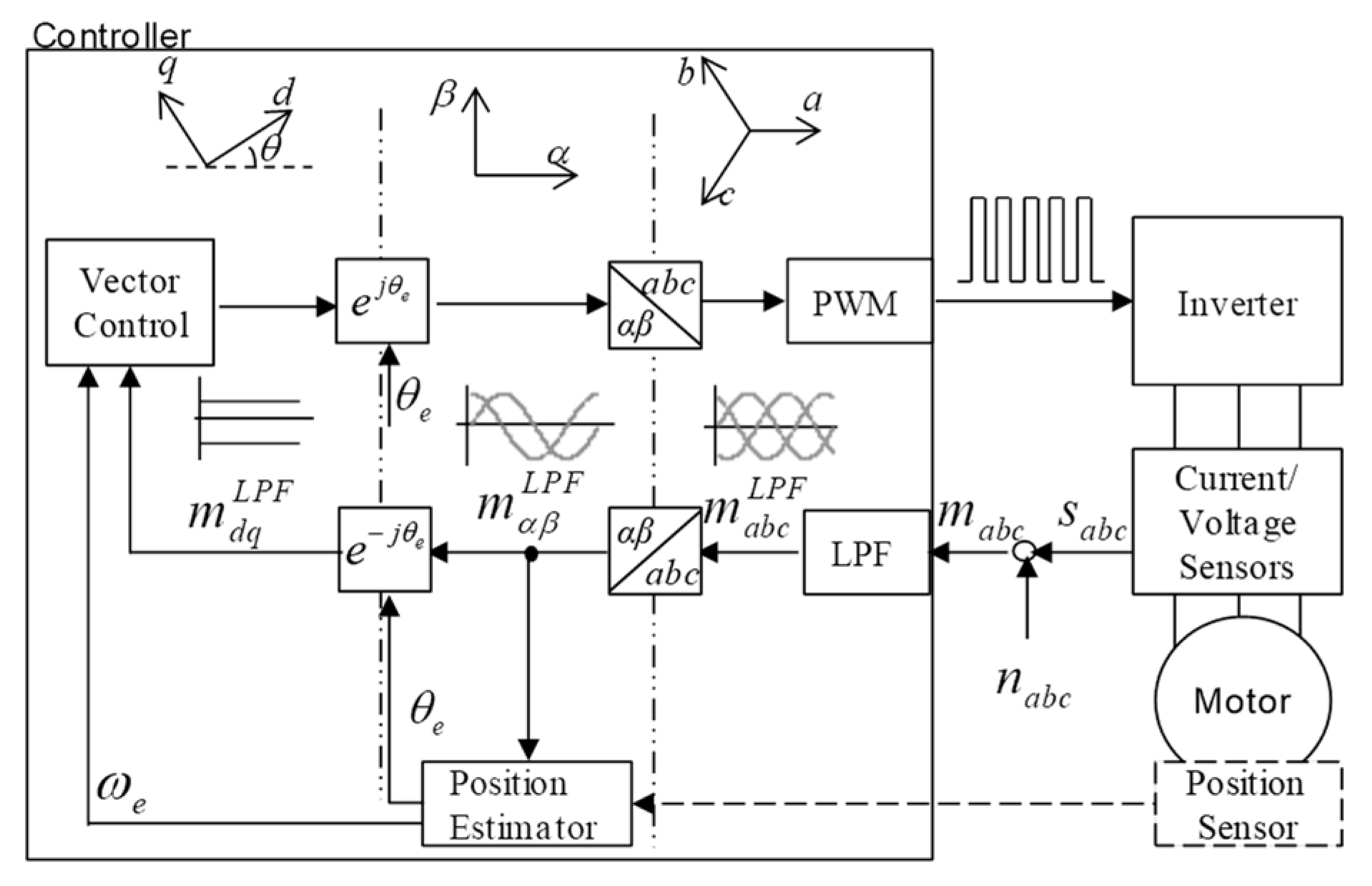
Figure 1 shows a general scheme of an AC drive system that consists of a controller, inverter, AC motor, and various sensors.
The controller executes a vector control algorithm for driving the AC motor. For ease of control, the electrical variables such as voltage, current, and flux in the a, b, and c phases of a three-phase system can be transformed to variables in orthogonal d and q axes of the synchronous reference frame. In addition to the vector control algorithm, high performance control and fault diagnosis algorithms are introduced. These methods use not only variables in the synchronous reference frame (
mdq) but also variables in the stationary reference frame (
mαβ), and the three-phase variables (
mabc) are directly used without transforms. The variables in the stationary reference frame are widely used for estimation algorithms based on vector tracking. The rotor position estimation algorithm for a sensorless drive is a typical case, as shown in
Figure 1. The three-phase variables are usually applied for fault detection and provide distinct information for isolating faulty phases.
2.2. General LPF
AC electric drive systems fed by a pulse width modulation (PWM) inverter include noise signals such as switching noise, sampling noise, and analog to digital conversion (ADC) noise. A digital low-pass filter (LPF) enhances signal integrity by eliminating undesirable frequency and noise components.
However, the inherent characteristics of the LPF cause gain attenuation and phase delay of the fundamental component. The gain attenuation and phase delay become larger as the fundamental frequency of the measured three-phase variables approaches the cut-off frequency of the LPF, i.e., as the frequency becomes higher.
The transfer characteristic of the first order LPF is given by:
where
ωc is the cut-off frequency.
The gain attenuation and phase delay of the LPF at synchronous frequency
ωe can be respectively given as (2) and (3) [
5,
6,
7,
8,
9]:
The phase delay results in cross-coupling of the current dynamics of the d-q axis in the synchronous reference frame. Moreover, the current regulation performance will be degraded and, in an extreme case, the current regulation loop may be unstable.
As the drive has to operate over a wide speed range, such frequency-sensitive gain attenuation and phase delay should be avoided. In addition, the cut-off frequency of the filter should be adjusted according to the synchronous frequency of the AC motors.
3. Programmable LPF (PLPF)
3.1. AC Drive Systems
Differently from the LPF, the PLPF adjusts its cut-off frequency according to the synchronous frequency. Moreover, it compensates for gain attenuation and phase delay of the fundamental component signal, which are caused by the LPF.
Gain compensation
G and phase compensation
P can be expressed by the inverse relationship of (2) and (3) as:
The gain attenuation and phase delay are compensated for by multiplying (4) and (5) by (1) as follows:
By use of the relationships of (7), (6) can be simplified as (8):
Equation (8) can be expressed using the orthogonal property of each axis in the stationary reference frames, as (9):
The cut-off frequency
ωc is determined to vary proportionally to the synchronous frequency
ωe of the AC motor as delineated in (10):
Finally, the PLPF is expressed as:
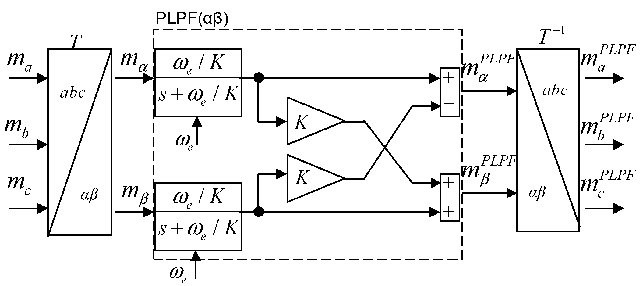
This conventional PLPF can only be applied to variables in the stationary reference frame. In order to obtain filtered three-phase variables, an inverse reference frame transformation is required, as shown in
Figure 2.
3.2. Extended PLPF
In this paper, an extended structure of the PLPF is proposed for direct filtering of three-phase variables. The details are as follows. If (12) is substituted into (8) and both sides are multiplied by
T−1, the extended PLPF is expressed as:
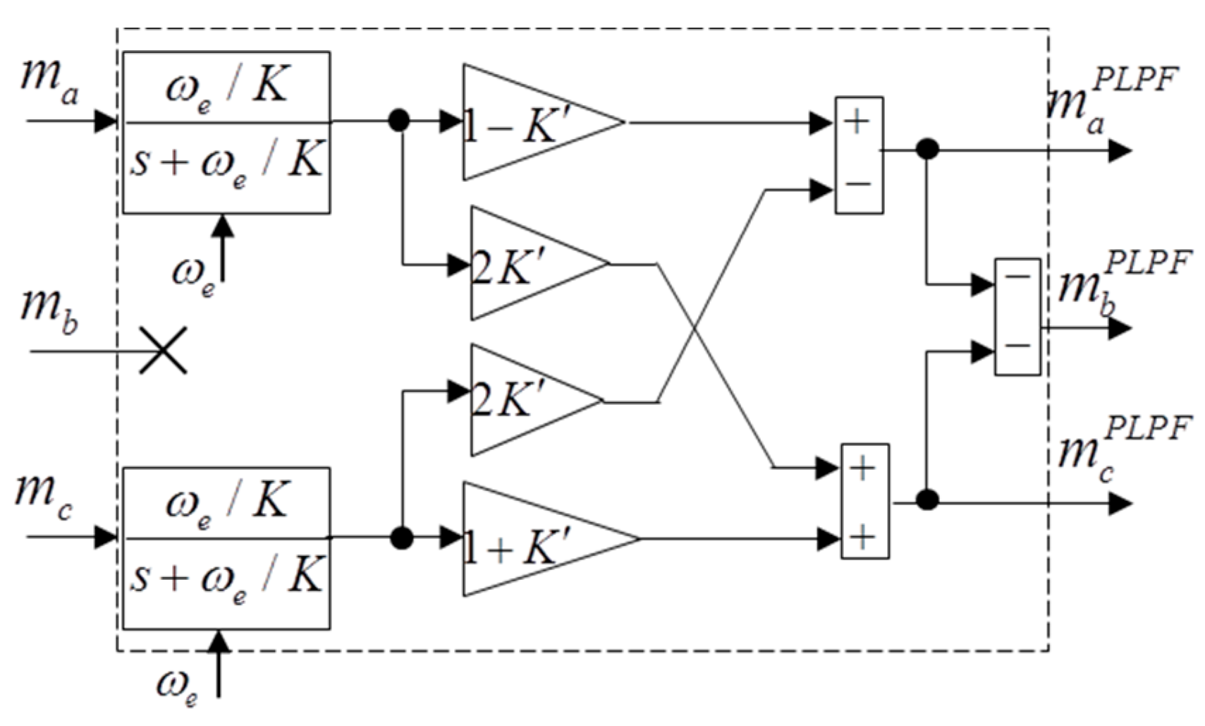
By applying Kirchhoff’s law, i.e.,
ma +
mb +
mc = 0, (13) can be written as (15):
Equation (15) can be simplified further using two-phase information through
mb = − mb –
mc as:
Figure 3 shows a block diagram of the final form for the extended PLPF.
4. Comparison between Two PLPFs
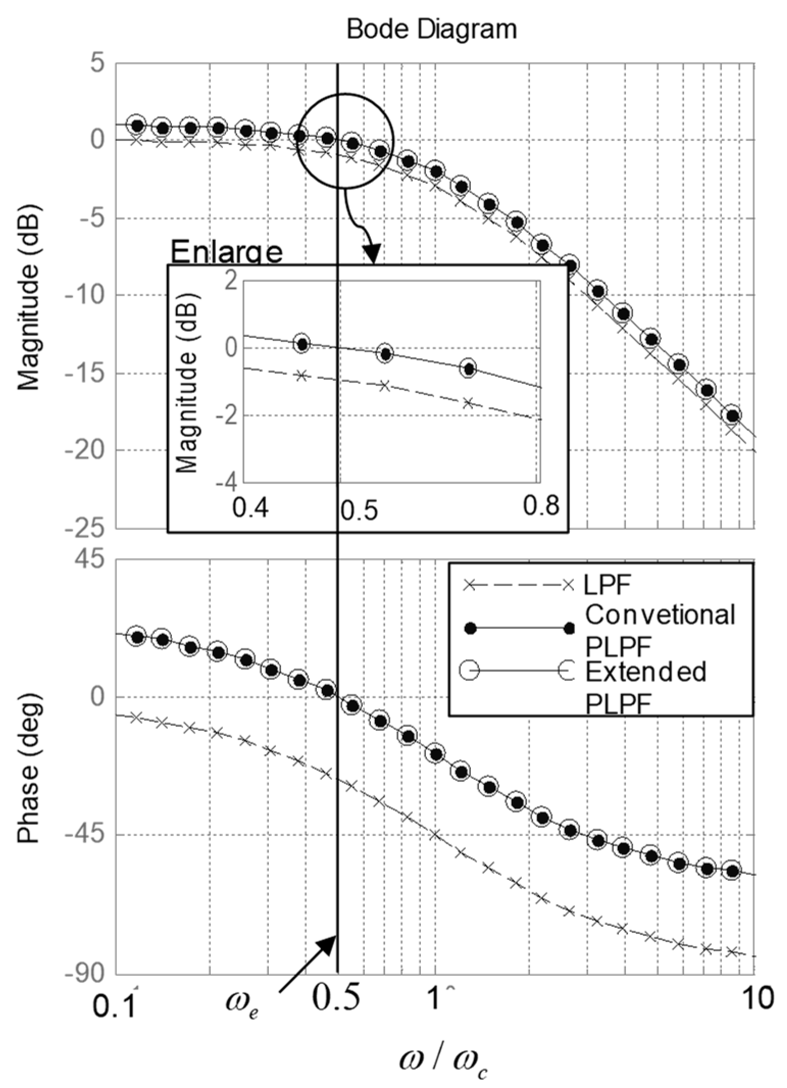
Figure 4 compares the bode plots among the general LPF, conventional PLPF, and extended PLPF. In an extreme case where the cut-off frequency is twice the synchronous frequency, the general LPF results in gain attenuation and phase delay of approximately −1 dB and 30 degrees, respectively. However, the conventional PLPF and extended PLPF provide the fundamental component without distortion by compensating for the gain attenuation and phase delay.
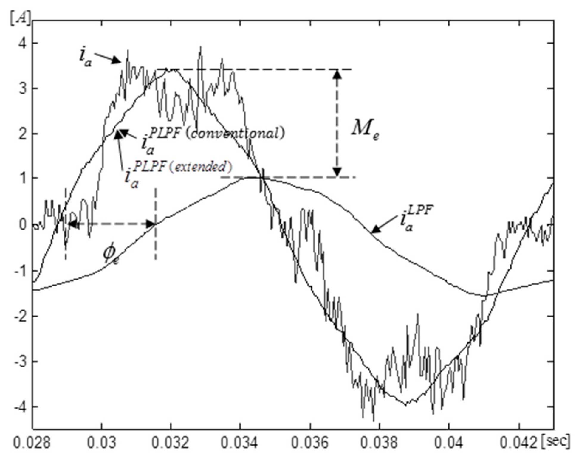
Figure 5 shows experimentally measured signals for phase currents. A 16-bit microcontroller, which has a 12-bit ADC and 16 kHz sampling rate, measures the signal from current sensors whose maximum rating is 150 A. The raw signal
ia includes high-level noise components. The PLPF eliminates the noise without gain attenuation and phase delay, in contrast with the LPF.
The conventional PLPF and extended PLPF are identical from the standpoints of filter performance and compensation performance, as shown in the above results. However, from a signal flow perspective, there is a difference between the two PLPFs.
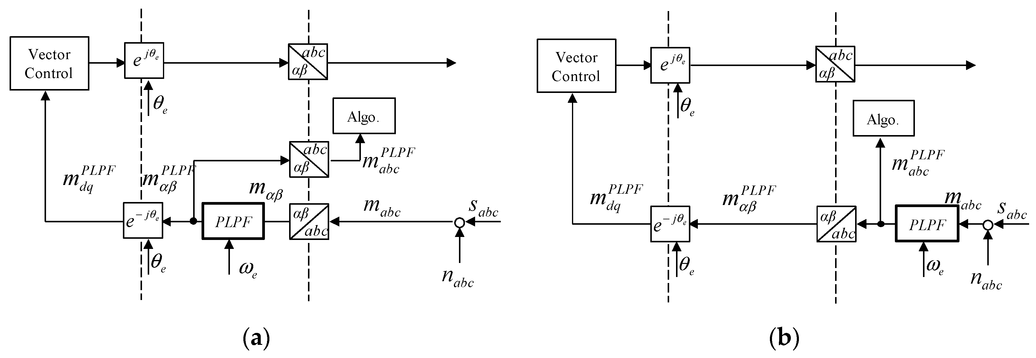
As shown in
Figure 6a, the conventional PLPF requires an inverse reference frame transformation in order to obtain filtered three-phase variables. Therefore, the signal flows are complicated and mix both three-phase variables and variables in the stationary reference frame when adding an algorithm that directly requires three-phase variables.
In contrast to the conventional PLPF, the extended PLPF can directly provide the filtered three-phase variables to the algorithm. The extended PLPF is more useful for making signal flows clear and intuitive when organizing the algorithm, as shown in
Figure 6b.
Table 1 compares the implementation equation between two PLPFs. The equations of the PLPF are discretized by using the backward Euler approximate method.
In recent years, commercial digital signal processors (DSPs) and microcontrollers have multiply and accumulate (MAC) instructions, which are useful for the calculation of digital signal processing, as follows:
The execution load between two PLPFs can be analyzed by counting the execution number of MAC instructions. The filter coefficient part, third phase calculation part, LPF, and gain and phase-compensation part in
Table 1 are commonly executed and required the same execution load in the two PLPFs. The case of the inverse transformation,
T−1 is not required in the extended PLPF because it deals with three-phase variables directly.
The microcontroller, from the DSC56F8xxx family of Freescale Semiconductor, Inc., provides software libraries for the forward and inverse transformations, T and T−1. Both libraries require approximately 80 clock cycles. In consideration of the 40 MHz clock frequency of the microcontroller, execution time of approximately 2μ seconds is required for the execution of T−1. The minimum requirement for implementing vector control of AC motor drives is 40 MHz, considering a nominal PWM frequency range from 10 to 20 kHz. This PWM frequency requires 50–100μ seconds of sampling time and execution time dead line. Adding filters having the same sampling time of PWM may be critical for keeping real-time properties. The extended PLPF can reduce this amount of time in comparison with the conventional PLPF.
5. Case Studies
5.1. Phase Current Measurement Based Dead-Time Compensation
To perform the correct status change of the power switches in the inverter leg, a PWM generator should insert a small amount of time between the required switching edges for top and bottom switches. This time is called dead time. The dead time results in a distortion between the actual voltage,
vxact, and the reference voltage,
vxref, as in (18) and (19):
where
Tdead is dead time,
Tpwm is PWM period,
Vdc is DC bus voltage.
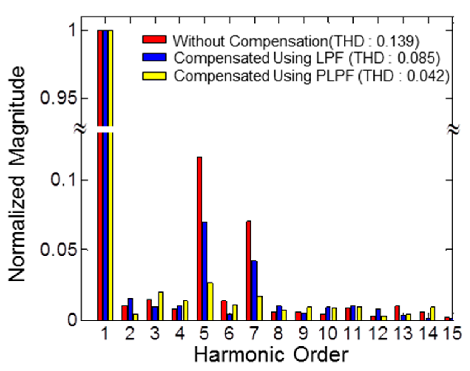
This distortion due to the dead time is one of main factors of 5 and 7th order harmonic components for three-phase current of electric motors [
16]. The harmonic components result as a torque ripple and zipper noise, which are critical technical issues in high performance electric control systems such as an electric power steering system.
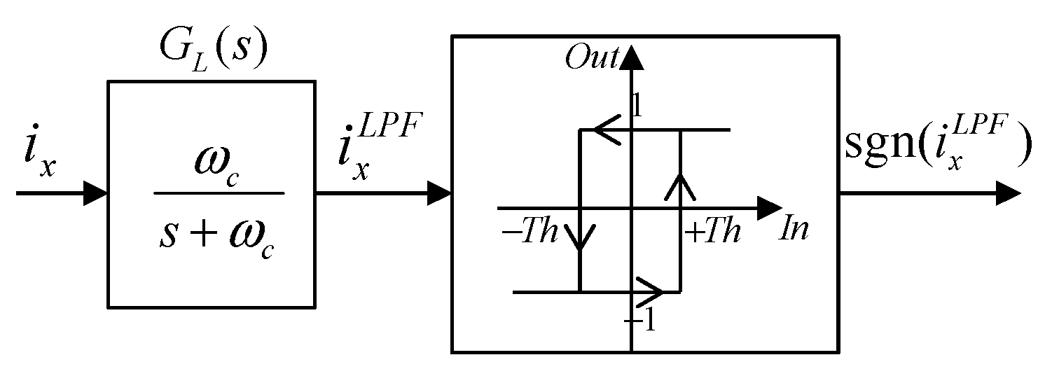
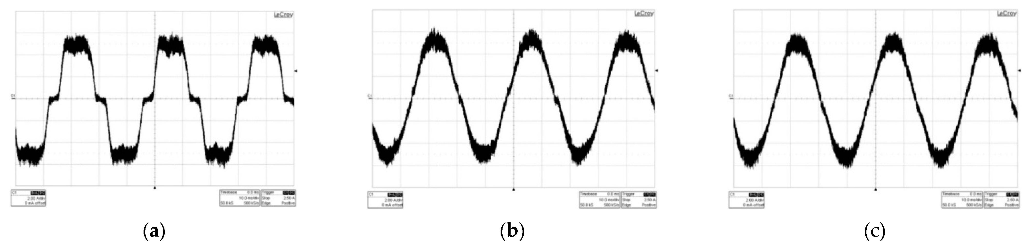
For the dead-time compensation, the LPF and hysteresis band are generally used as shown in
Figure 7. However, the LPF and hysteresis band has limitations when the current value is relatively small, as shown in
Figure 8b. The polarity detection using the PLPF is an alternative solution of a conventional method which uses a general low-pass filter and hysteresis bands in order to avoid jittering due to noises as shown in
Figure 8c.
Figure 9 shows Total Harmonic Distortion (THD) analysis of phase currents according to compensation methods.
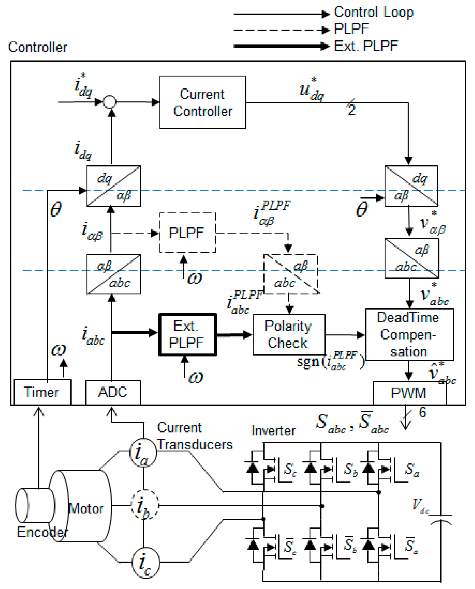
When applying PLPF to the dead-time compensation, the extended PLPF is more intuitive and efficient than the conventional PLPF because the measured three-phase currents are directly used for compensating three-phase voltages, as explained in
Figure 10. All algorithms are implemented in one layer of three-phase variables without any cross-layer signal flow.
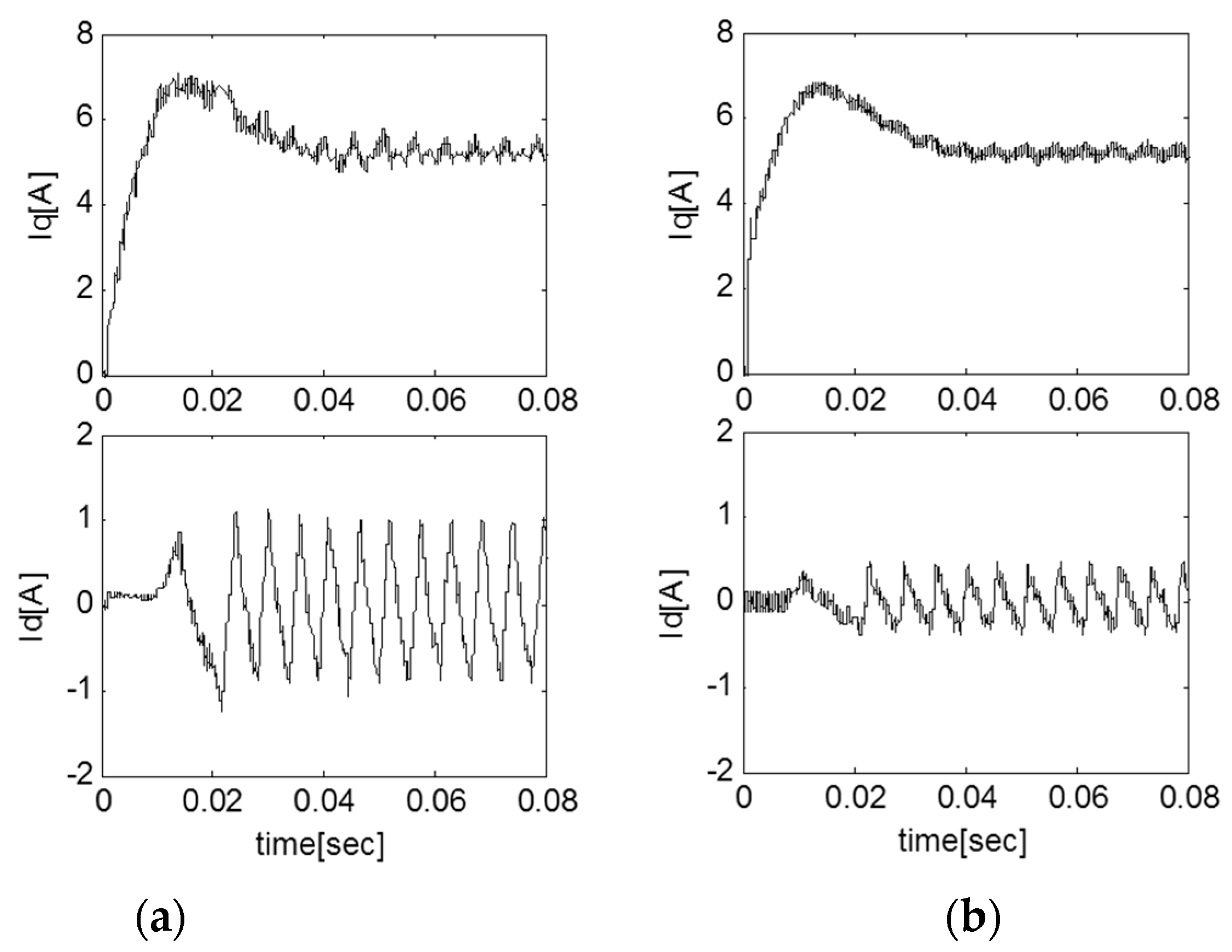
Figure 11 shows d- and q-axis current during start-up tests. The distortion of phase current results in d- and q-axis current ripples. As shown in
Figure 11b, the proposed PLPF can be effectively applied during the start-up and transient state. However, for the transient performance, the fractional value
K between the cut-off frequency and synchronous frequency in Equation (10) should be carefully determined. If higher speed dynamics is required, a smaller value of
K should be selected.
5.2. Phase Voltage Measurement Based Open-Phase Fault Detection
There have been many studies on the detection of the open-switch faults. The detection methods for open-switch faults are largely classified into two categories, according to whether the methods are current-based or voltage-based [
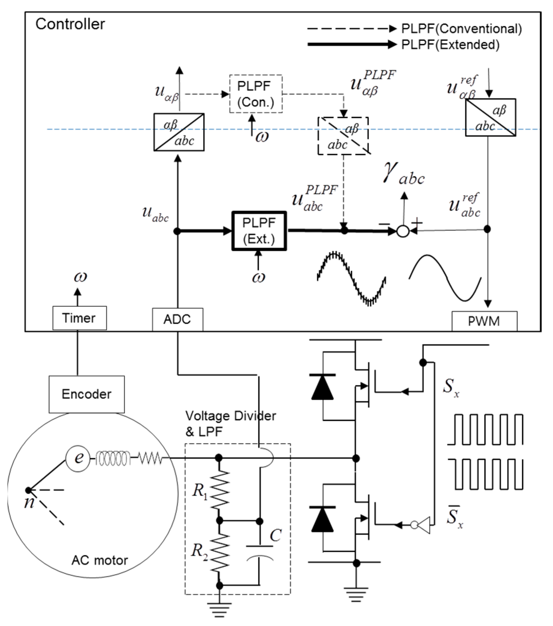
15]. In current-based methods, it is difficult to isolate if a fault has occurred in the inverter from within the machine under fast dynamic load conditions. In contrast, the voltage-based method has the advantage of isolating the source of faults. However, the voltage-based method requires additional conditioning circuits, including voltage dividers and filtering circuits, in order to remove high frequency switching components of a pulse width modulation (PWM) inverter.
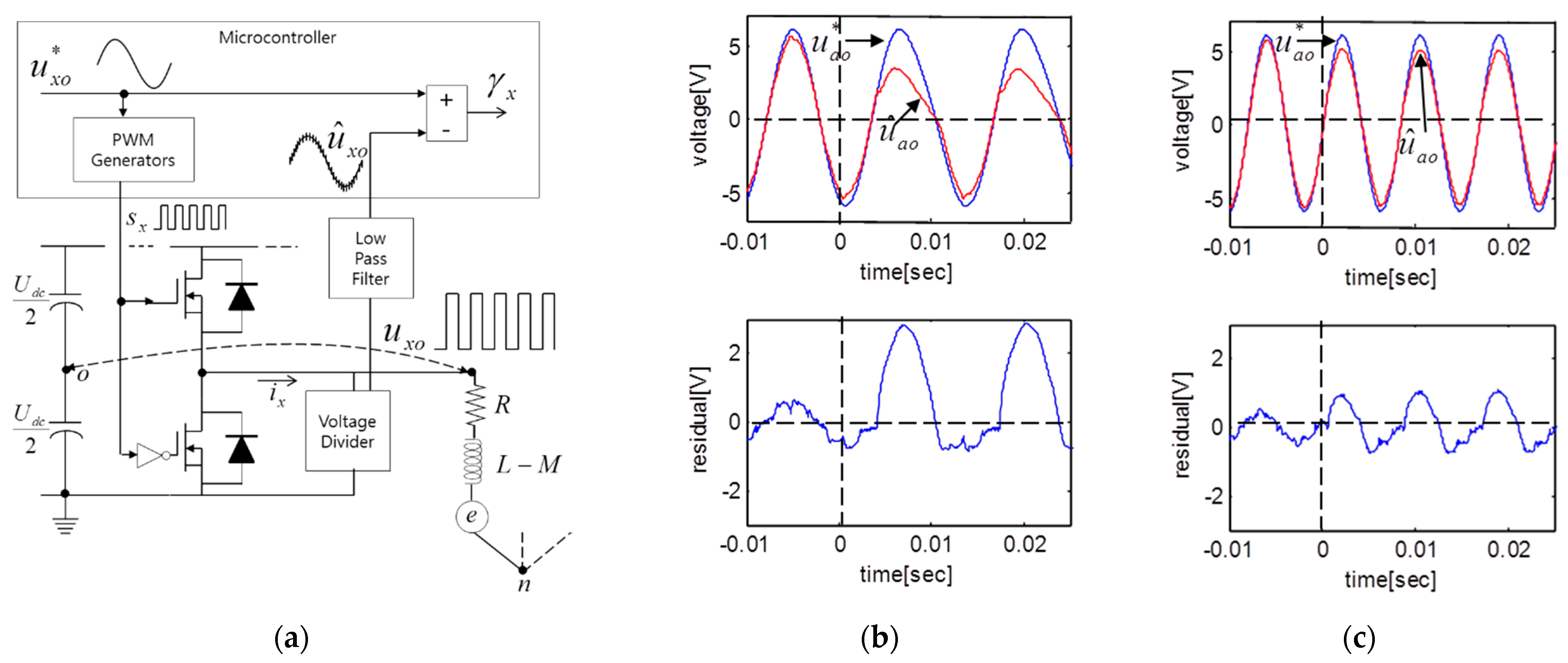
Figure 12a shows the basic concept of detection of open-switch faults of one phase using voltage measurements. The measured voltage,
, is directly compared with the reference value,
, of the controller. The comparison result is used as an instantaneous residual in order to detect whether the switch state is normal or open faulted.
Figure 12b,c show the experimental results in order to indicate the instantaneous residual variation both at the normal and at the fault state. The top switch of phase A is open at zero seconds, and the peak value of the reference voltage is 6 V.
Figure 12a shows the case with a load torque of approximately 0.5 Nm; in
Figure 12b the load torque is 0.1 Nm. The specifications and parameters of the sample motor are given in
Table 2. The residual varies according to the operating conditions because the angular velocity and the back EMF vary according to the amount of applied loads [
15].
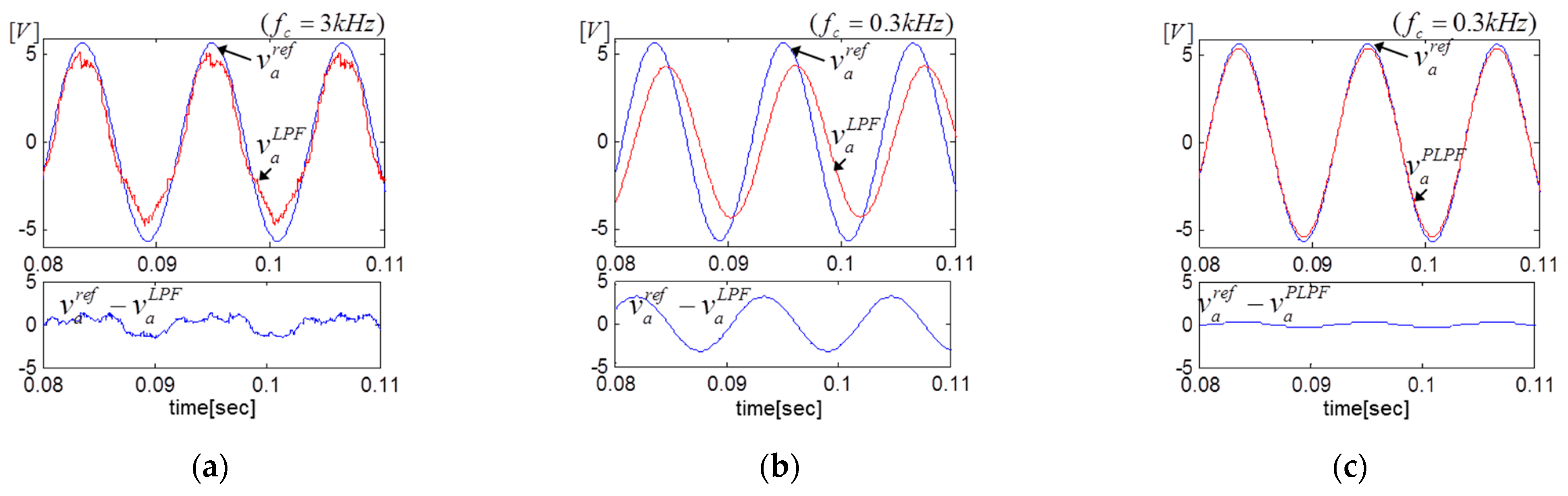
As mentioned in previous sections of this paper, the low-pass filter (LPF) circuit with a proper cut-off frequency is indispensable but the LPF causes a gain attenuation and phase delay. To determine proper cut-off frequency is the main consideration to avoid mis-alarms or false alarms of the open-phase detection, as shown in
Figure 13.
With a higher cut-off frequency of 3 kHz, as shown in
Figure 13a, the gain attenuation and phase delay can be neglected, but it is not enough to remove the switching components of voltage. Higher harmonic components remain, thus making it difficult to detect normal or fault conditions under the light load conditions. If the cut-off frequency is reduced to 300 Hz in order to strongly remove the switching components, the gain attenuation and phase delay effects increase, as shown in
Figure 13b.
The proposed extended PLPF is directly applied to the phase voltage measurements to remove high-frequency switching components and to avoid the gain attenuation and phase delay effects of low-pass filter, as shown in
Figure 13c. In contrast to the conventional PLPF, the extended PLPF makes the signal flows clear and intuitive only in the three-phase variable layer, as shown in
Figure 14. It also helps to reduce execution time in the same manner as for dead-time compensation, as discussed in
Section 5.1.
6. Conclusions
This paper proposes an extended structure of a programmable low-pass filter (PLPF) and compares it with the conventional PLPF. The two PLPFs are identical from a filter performance standpoint, and both filters adjust cut-off frequency according to the synchronous frequency, and compensates for gain attenuation and phase delay.
The conventional PLPF, however, can only be applied to variables in the stationary reference frame. In order to obtain filtered three-phase variables, an inverse reference frame transformation is required. However, the extended structure, which includes reference frame transformations, can be directly applied to three-phase variables and can remove the noise in the earlier stage before transformation. The extended PLPF is more useful for making signal flows clear and intuitive when organizing an algorithm that directly requires three-phase variables, e.g., inverter dead-time compensation based on a polarity check of phase currents, and inverter open-switch fault detection based on measurements of phase voltages for low-cost automotive applications such as electric pump and fans.
From comparison results for the implementation equations between the two PLPFs, the extended PLPF reduces the execution time by 2–3 μ seconds in comparison with the conventional PLPF based on a low-cost microcontroller with a 40 MHz clock frequency. Although this may appear to be a small improvement, the reduction in the execution time is not a negligible contribution considering that the entire control algorithm should be executed within 50–100 μ seconds of the general PWM period (10–20 kHz PWM frequency) and the software of the AC drive system is becoming more complicated and more integrated.
Author Contributions
Methodology, C.C.; formal analysis, W.L.; software, C.C; writing—original draft preparation, C.C.; writing—review and editing, W.L.; visualization, C.C.; supervision, W.L. All authors have read and agreed to the published version of the manuscript.
Funding
This research received no external funding.
Institutional Review Board Statement
Not applicable.
Informed Consent Statement
Not applicable.
Data Availability Statement
Not applicable.
Acknowledgments
The authors express their gratitude to Myunghwa Ind. Co., Ltd. and Changwon National University for administrative and technical support. The authors would also like to thank the reviewers and the editor for their helpful comments on an earlier version of the manuscript.
Conflicts of Interest
The authors declare that they have no conflict of interest.
References
- Carpaneto, M.; Fazio, P.; Marchesoni, M.; Parodi, G. Dynamic Performance Evaluation of Sensorless Permanent-Magnet Synchronous Motor Drives With Reduced Current Sensors. IEEE Trans. Ind. Electron. 2012, 59, 4579–4589. [Google Scholar] [CrossRef]
- Kan, L.; Zhu, Z.Q.; Qiao, Z.; Jing, Z. Influence of Nonideal Voltage Measurement on Parameter Estimation in Permanent-Magnet Synchronous Machines. IEEE Trans. Ind. Electron. 2012, 59, 2438–2447. [Google Scholar]
- Kwon, Y.-C.; Kim, S.; Sul, S.-K. Voltage Feedback Current Control Scheme for Improved Transient Performance of Permanent Magnet Synchronous Machine Drives. IEEE Trans. Ind. Electron. 2012, 59, 3373–3382. [Google Scholar] [CrossRef]
- Lee, C.S.; Yoon, M.H.; Hong, J.P.; Kim, Y.K. Novel Rotor Design Of Wound Field Synchronous Motor For Torque Ripple Reduction In ISG System. Int. J. Automot. Technol. 2019, 20, 307–312. [Google Scholar] [CrossRef]
- Bose, B.K.; Patel, N.R. A programmable cascaded low-pass filter-based flux synthesis for a stator flux-oriented vector-controlled induction motor drive. IEEE Trans. Ind. Electron. 1997, 44, 140–143. [Google Scholar] [CrossRef]
- Da Silva, L.E.B.; Bose, B.K.; Pinto, J.O.P. Recurrent-neural-network-based implementation of a programmable cascaded low-pass filter used in stator flux synthesis of vector-controlled induction motor drive. IEEE Trans. Ind. Electron. 1999, 46, 662–665. [Google Scholar] [CrossRef]
- Shin, M.-H.; Hyun, D.-S.; Cho, D.-S.; Choe, S.-Y. An improved stator flux estimation for speed sensorless stator flux orientation control of induction motors. IEEE Trans. Power Electron. 2000, 15, 312–318. [Google Scholar] [CrossRef]
- Karanayil, B.; Rahman, M.F.; Grantham, C. An implementation of a programmable cascaded low-pass filter for a rotor flux synthesizer for an induction motor drive. IEEE Trans. Power Electron. 2004, 19, 257–263. [Google Scholar] [CrossRef]
- Ghaderi, A.; Hanamoto, T. Wide-Speed-Range Sensorless Vector Control of Synchronous Reluctance Motors Based on Extended Programmable Cascaded Low-Pass Filters. IEEE Trans. Ind. Electron. 2011, 58, 2322–2333. [Google Scholar] [CrossRef]
- Kim, S.-Y.; Park, S.-Y. Stator Flux Oriented Sensorless Vector Control with Phase/Gain Compensated LPF for Induction Motor. Trans. Korean Inst. Electrial Eng. B 2005, 54, 201–207. [Google Scholar]
- Choi, C.; Lee, K.; Lee, W. Design and Temporal Analysis of Hardware-in-the-loop Simulation for Testing Motor Control Unit. J. Electr. Eng. Technol. 2012, 7, 366–375. [Google Scholar] [CrossRef] [Green Version]
- Choi, C.; Lee, W. Analysis and Compensation of Time Delay Effects in Hardware-in-the-Loop Simulation for Automotive PMSM Drive System. IEEE Trans. Ind. Electron. 2012, 59, 3403–3410. [Google Scholar] [CrossRef]
- Jeong, S.-G.; Park, M.H. The analysis and compensation of dead-time effects in PWM inverters. IEEE Trans. Ind. Electron. 1991, 38, 108–114. [Google Scholar] [CrossRef]
- Leggate, D.; Kerkman, R.J. Pulse-based dead-time compensator for PWM voltage inverters. IEEE Trans. Ind. Electron. 1997, 44, 191–197. [Google Scholar] [CrossRef]
- Choi, C.; Lee, W. Design and evaluation of voltage measurement-based sectoral diagnosis method for inverter open switch faults of permanent magnet synchronous motor drives. Electr. Power Appl. IET 2012, 6, 526–532. [Google Scholar] [CrossRef]
- Musumeci, S.; Mandrile, F.; Barba, V.; Palma, M. Low-Voltage GaN FETs in Motor Control Application; Issues and Advantages: A Review. Energies 2021, 14, 6378. [Google Scholar] [CrossRef]
| Publisher’s Note: MDPI stays neutral with regard to jurisdictional claims in published maps and institutional affiliations. |
© 2022 by the authors. Licensee MDPI, Basel, Switzerland. This article is an open access article distributed under the terms and conditions of the Creative Commons Attribution (CC BY) license (https://creativecommons.org/licenses/by/4.0/).


