Article

Numerical Modeling of the Hydrodynamic Performance of Slanted Axial-Flow Urban Drainage Pumps at Shut-Off Condition

1
State Key Laboratory of Fluid Power and Mechatronic Systems, Zhejiang University, Hangzhou 310027, China
2
School of Mechanical Engineering, Zhejiang University, Hangzhou 310027, China
3
Hangzhou Hangfa Electrical Equipment Co., Ltd., Hangzhou 311251, China
*
Author to whom correspondence should be addressed.
Energies 2022, 15(5), 1905; https://doi.org/10.3390/en15051905
Submission received: 14 February 2022 / Revised: 27 February 2022 / Accepted: 3 March 2022 / Published: 4 March 2022
(This article belongs to the Special Issue Sustainable and Low-Carbon Technologies for Future Energy Systems)

Abstract

:
Increasing extreme rainfall events caused by global climate change have had a significant impact on urban drainage systems. As a critical component of a pumping station, a large-scale slanted axial-flow pump (SAFP) featuring high specific speed plays a critical role in mitigating urban flooding and waterlogging. In this study, to reveal the transient characteristics of a SAFP at shut-off conditions, a computational fluid dynamics (CFD) based approach with dynamic mesh was proposed. Multiple shut-off conditions with various shut-down speeds of the sluice gate (SG) were modeled. Our analysis demonstrated that both the shut-off conditions and the slanted structure have conspicuous impacts on the hydrodynamic performance of a SAFP. Reducing the shut-down speed leads to a greater reverse flow rate and higher runner speed. The water hammer effect was simulated with different shut-down speeds, increasing the water head by 5.07–10.42 m, the axial force by 163.46–297.06 kN∙m, and the axial moment by 116.05–224.01 kN∙m. Compared with the axial direction, moments in the radial directions were found with more obvious oscillation as a result of stronger rotor–stator interaction. Due to the gravitational effect of the slanted structure, the fluctuation of the runner in vertical direction presented an off-axis characteristic compared with the horizontal one. As the SG speed increased, pressure fluctuations gradually decreased at various locations across the SAFP.

1. Introduction

In recent years, global warming has caused a significant increase in extreme weather. The insufficient drainage capacity of urban sewer systems and rapidly increasing water levels often expose cities to the risk of flooding and waterlogging [1,2,3]. In order to quickly mitigate the danger of flooding and waterlogging, large-scale pumping stations have been extensively constructed in large cities [4,5,6,7,8,9,10]. In urban drainage pump stations, axial-flow pumps have been widely used because of their relatively simple structure and good performance with a low head section. Among the vertical, horizontal and slanted axial-flow pumps, slanted axial-flow pumps (SAFPs) have been increasingly adopted by urban drainage pump stations, since they are more economical to construct, more convenient to maintain and superior in operation performance, by virtue of their extraordinarily simple and compact structure [11]. A few studies have been conducted on it. Wang et al. [12] analyzed the operation parameters and characteristics of a SAFP during a transient process under different flow rates. Yang et al. [13] studied how the installation height of a SAFP influences the external and force characteristics, and proposed the reference nominal height of pump concept. Zhang et al. [14] launched research on the hydraulic and cavitation characteristics of a SAFP with different turbulence models, and found that the predictive performance of a filter-based model was better than that of a k-ε model. Kang et al. [10] investigated the flow characteristics of a SAFP in direct and reverse mode. According to their results, cavitation only existed in the direct mode. In order to reveal the reason for flow deviation in the s-shaped flow passage in a SAFP, Wang et al. [15] carried out numerical calculations in a 15° model and observed the detailed flow mechanism. To find out the reason that resulted in impeller damage and vortex in a SAFP, Yang et al. [11] performed numerical calculation to study the pressure fluctuations under different flow rates. While the slanted structure of a SAFP will lead to some specific motion characteristics that influence the pump’s safety, nonetheless, the aforementioned research has not mentioned this. Additionally, these studies revolved around the conventional pump and flow passage, which neglected the interaction between the pump and the SG.
Transient processes, such as power-on, shut-off, and flow rate adjustment, which are accompanied by the greatest instability during pump operation, are vital during pump operation [16,17,18,19]. If not properly handled, serious vibration, noise, and cavitation phenomena may happen and lead to damage to the pump and the pipe system, or eventually induce pump station breakdowns [20,21,22]. The surge in extreme weather has also brought more uncertainties to pumps’ transient processes. Hence, attention should be paid to the transient processes of large-scale pumps. With the development of computer technology, accurate CFD numerical calculation for large-scale units is accessible and convenient [23]. Compared with experiments, using the numerical method for large-scale units can circumvent damages resulting from such tests. In this decade, many scholars have launched studies on transient processes of large-scale pumps based on the CFD method. Fu et al. [24] conducted experimental and numerical studies on the transient characteristics during the start-up of an axial-flow pump with a gate opening motion. According to the CFD results, the transient characteristic parameters of the pump, such as runner speed, head, and flow rate, changed dramatically. The vortex core region also reached the maximum area and number at a moment during the start-up process. Han et al. [25] numerically studied the transient characteristics of pump turbines under pumping conditions with different guide vane openings based on the dynamic mesh technology. Compared with the constant guide vane opening condition, the flow in the pump was more unstable under moving guide vane conditions, and there were complex vortex structures and flow blocking phenomena with small guide vane openings. Liu et al. [26] applied a CFD-based fluid volume method to analyze the internal and external characteristic parameters of the pumping mode, braking mode, and turbine mode during the stoppage process in an axial-flow pump with a siphon outlet. They found that the opening time of the air valve located at the top of the siphon outlet greatly influenced the performance. Kan et al. [27] predicted and compared the transient characteristics of a shaft extension tubular pump during shut-off with two kinds of numerical prediction model, which supposed the upper layer of the inlet reservoir and the outlet reservoir as a free air layer and a rigid-lid layer, respectively. Their results showed that the maximum runaway speed of the former model was closer to the experimental results. In order to find out the flow mechanism during the closure process of guide vane, Li et al. [28] launched a 3-D simulation with incompressible fluid and a shear stress transition turbulence model. They utilized dynamic mesh to simulate the closing process of the guide vane, and analyzed the performance characteristics and the flow phenomenon during this period. Wang et al. [29] simulated the rotation of wicket gate vanes from rated condition to shut-off condition with a novel dynamic mesh method. The flow rate, shaft power, and pressure were monitored and analyzed by means of Fast Fourier Transform and Continuous Wavelet Transform. The above researchers have revealed the internal mechanism of several large-scale pumps’ transient processes based on the CFD method. Among the transient processes of SAFPs, the shut-off condition has drawn strong attention for the sake of the exposure to reverse flow of the rotor system without any electric control. However, throughout these investigations, the shut-off conditions of SAFPs with SG motion have not been mentioned, meaning that there is no available reference for analyzing this transient process.
In most transient processes, the water flow switches, such as the SGs of axial-flow pumps and the wicket gates of mixed-flow pumps, are the core components to implement the regulation order [30,31,32]. If the switch is not properly handled, a large reverse flow rate may contribute to positive axial force [33,34]. Even worse lifting and runaway phenomena may happen, accompanied by strong vibration, which is harmful for the long-term stable operation of the unit [35,36,37,38]. Consequently, the proper operation speed of the switch is indispensable for guaranteeing the safety of the unit [39]. Cui et al. [40] proposed a new non-linear evaluation function to optimize the closing speed of a turbine gate under different water conditions. According to the one-dimensional (1-D) calculation results, this function was better in terms of the distribution of the safety margins of each optimization objective than the traditional one. With the aim of detecting the influence of the guide vane closing law on the load rejection process, Yao et al. [41] designed five cases with different turning points in the process. After considering some typical dynamic parameters obtained by 1-D calculation and safety of the pump turbine, they determined the ultimate guide vane closing case. Taking the maximum overpressure and the minimum pump turbine overspeed during full load rejection as the goals, Rezghi et al. [42] optimized the guide vane closing law and the position of the surge tank. Their 3-D simulation results indicated that the optimized guide vane closing law and surge tank position could reduce the maximum overpressure and the pump turbine overspeed to 4.2% and 7.1%, respectively. The shut-down speed of the SG is essential for SAFPs during shut-off conditions to guarantee the safety of the pump system [43]. If not appropriately designed, the gate will suffer from huge impact and pulsations, resulting in friction and wear between the SG and the wall. What is worse, the incontrollable flow will lead to great uncertainty in the runner, making it harmful for the safety of the system and reducing the life of the SG [44]. However previous studies have either focused on 1-D calculation, which are not as reliable as 3-D ones [45], or they were not related to gate closing speed, making them inadequate for providing SAFP units with references for gate regulation.
In order to improve the hydrodynamic performance of a SAFP during shut-off conditions, and to find out how the SG shut-down speed and the slanted structure affect the pump’s performance, a CFD-based approach with dynamic mesh was proposed. Multiple shut-off conditions with various shut-down speeds of the SG were modeled. The incompressible simulation was based on the SST k-ω turbulence model. The layering dynamic mesh method was adopted to actualize the shut-down process of the SG. The hydraulics, force and moment, and pressure fluctuation characteristics were analyzed and compared in the five cases. This study helped to uncover the specific internal mechanics of SAFPs during the shut-off condition, and provides an available reference for designing SG shut-down speeds. The article is organized as follows. Section 2 introduces the modeling process of the SAFP and the CFD-based hydrodynamic performance research approach. Section 3 analyzes the hydrodynamic performance of different shut-off conditions in terms of the hydraulics, force, moment, and pressure fluctuation characteristics. Lastly, the main conclusion is presented in Section 4.

2. Materials and Methods
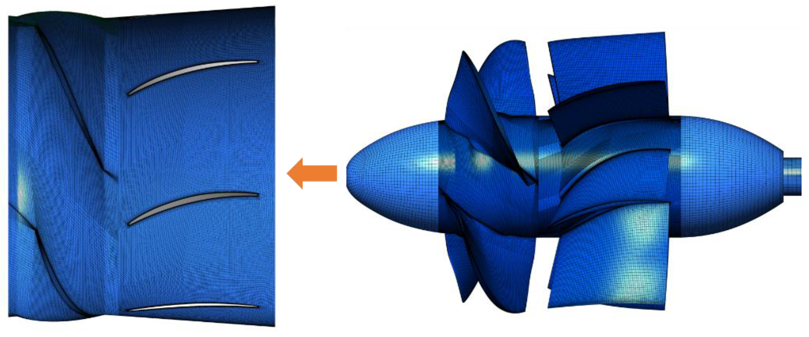
2.1. Physical Model

The research pump is a 20° SAFP that will go online in an urban drainage pump station of China in the near future. The diameter of the runner, the rated flow rate, rated rotation speed, and rated head are 3.6 m, 50 m3, 113 rpm and 4.6 m, respectively. The pump system consists of an s-shaped inlet and outlet conduit, a slanted medium conduit with a runner and a fixed rear guide vane inside it, and downstream and upstream reservoirs, as shown in Figure 1. The number of runner blades and guide vane blades is 4 and 7, respectively.

2.2. Mesh Description and Independence Test

In consideration of the large scale and geometry complexity of the computational domain, a hexahedral structured mesh was adopted for all domains to maximize the calculation’s accuracy. Block splitting methods varied among domains to generate mesh with high structural adaptability, especially for domains that enclosed the runner and guide vane. Partial encryption was performed near the blades and other locations with small sizes. The detailed mesh scheme is displayed in Figure 2. To ensure an appropriate element size, five different generation schemes were designed to check the mesh’s independence, as seen in Table 1, for which steady-state calculations were performed to obtain the external characteristics of these schemes. It was found that when the number of total elements reached 9,046,973, the head ascends too slowly to create a great impact. Therefore, Scheme 4 was adopted, considering its higher calculation accuracy and fewer calculation costs. The y+ value of the first mesh layer near the wall regions is 1~10.

2.3. Numerical Schemes and Settings

As the flow rate in this article was much slower than acoustic velocity, the 3-D unsteady flow during the shut-off condition was assumed to be incompressible. The temperature was supposed to be constant; correspondingly, the mass and energy of single-medium water were conserved [46]. The Reynolds-averaged flow governing equations that solve the viscous turbulence flow can be written as follows [47,48,49]:
( ρ u ) = 0
ρ u t + ( ρ u ) u = ρ f i p + μ 2 u
where ρ is the density of the fluid, u is the velocity, p is the static pressure, ∇ is the Hamilton operator, ∇2 is the Laplacian operator, μ is the viscosity of the fluid, and fi is the external body force term. In previous transient studies of large-scale fluid machinery such as axial-flow pumps, mixed-flow pumps, and turbines, the shear–stress transport (SST) k- ω turbulence model has been widely used for its good applicability to these kinds of 3-D models [15,27,28,30,35,36,37,50,51]. The SST k-ω turbulence model blends the advantages of the k-ω turbulence model and the k-e turbulence model, showing great accuracy in calculations with strong swirling flow with high shear and great sensitivity to adverse pressure gradients. Therefore, this study utilized the SST k-ω turbulence model to carry out the governing equations.
The shut-off transient condition in this study was simulated with the commercial software ANSYS Fluent 20.0, based on the finite volume method. The SIMPLEC algorithm was adopted for coupling pressure and velocity. A second-order scheme was chosen to discretize the pressure items. A second-order upwind scheme was utilized to discretize the momentum item, and a first-order upwind scheme was used for the kinetic energy of turbulence and the specific dissipation rate.

2.4. Boundary Conditions

Owning to the large scale of the calculation model in this study, gravity was considered during the simulation. Hence, the fluid flow surfaces of the downstream and upstream reservoir were set as pressure gradient boundary conditions. However, for the shut-off condition, the three surfaces of the downstream reservoir were set as outlet boundaries and the three surfaces of the upstream reservoir were set as inlet boundaries. The water heights of both reservoirs were in accordance with the designed scheme. All walls were supposed to be smooth, and the stationary walls were set as no-slip boundary conditions. In order to avoid the influence of reservoir size, the length and width of the reservoir was set to at least 5 times the inlet and outlet channels’ cross-section size.

2.5. Validation of Numerical Calculation

To verify the reliability of the simulation settings, the external characteristic curves of the simulation, and an experiment obtained from a model pump (Figure 3a), are drawn and compared, as seen in Figure 3b. The conversion formulas of the corresponding flow rate, head, shaft power, and efficiency between the prototype and the model pump are exhibited in Equations (3) and (6).
Q = λ 3 n n M Q M
H = λ 2 ( n n M ) 2 H M
P = λ 5 ( n n M ) 3 P M
η = ρ g Q H 1000 P
where Q, H, P, and n, and QM, HM, PM, and nM represent the external characteristics and rated speed of the prototype pump and model pump respectively, and λ is a dimensionless coefficient which equals the ratio of the impeller diameter of the prototype to that of the model pump.
According to Figure 3b, it can be observed that the changing trends of the two groups of curves are almost the same. Under a large flow rate, the head and efficiency between the experiment and numerical calculation differed the most. This is reasonable in reality, as flow leakage and frictional loss are aggravated under a larger flow. The maximum deviation of head and efficiency were all less than 10%, indicating that the simulation settings were convincing and supportive for the following analysis.

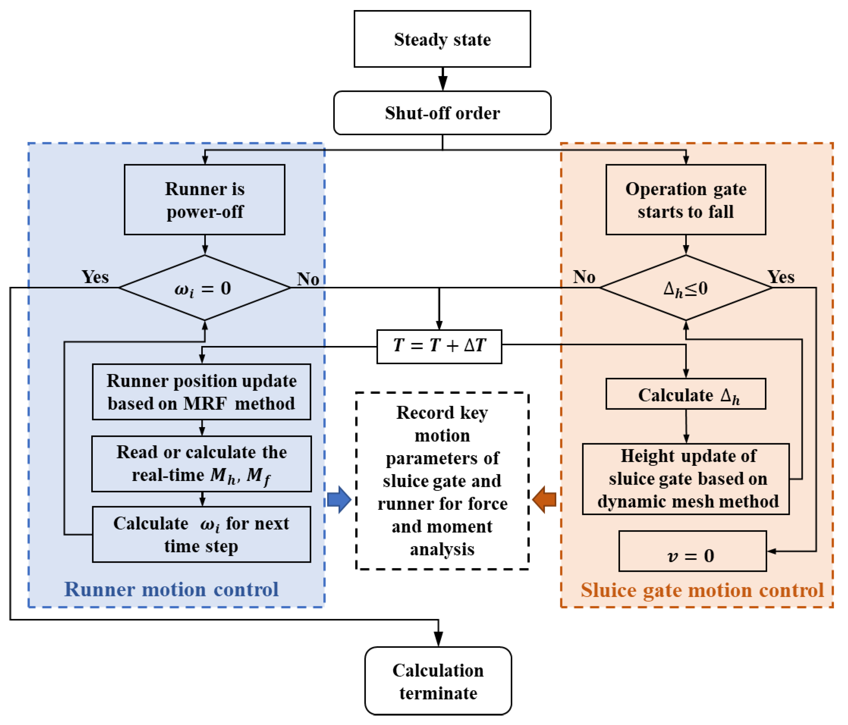
2.6. Collaborative Control Schemes of the SG and Runner

To determine how the SG shut-down speed influences the pump performance, various SG speeds, which needed to be within the achievable range of the pump station shown in Figure 4, were investigated. Balancing the computational cost and research accuracy, five cases (Case 1 to Case 5) with different SG speeds, which were 10 m/min, 12.5 m/min, 15 m/min, 17.5 m/min, and 20 m/min, were designed.
The four flap doors located on the SG were simplified to plane surfaces, as they mainly work during power-on conditions [24]. The system state at every time step is actualized through cooperative control of the runner and the SG, a schematic of which is shown in Figure 5. As for the runner, the speed at every time step was calculated according to the moment balance equation shown in Equations (7) and (8).
J d ω d t = M h + M f
ω i + 1 = ω i + M h + M f J × Δ T
where wi, wi+1, ΔT, Mh, Mf, and J stand for the rotation speed of the current time step, the rotation speed of the next time step, the time step size, the hydraulic moment, the mechanical resistance moment, and the inertia moment of the runner, respectively.
If we suppose that the SG descends at a constant speed, the opening of SG can be calculated as Equation (9), where t, v, Δh, and Gh stand for cumulative time, SG speed, remaining height at the gate port, and the designed height of the gate, respectively. The grid of the SG was divided by a hexahedral structured mesh, so a layering dynamic mesh method could be utilized to simulate the movement of the SG. Besides, the motion of the SG during the calculation could be actualized by a user-defined function method.
Δ h = G h v × t

3. Results and Discussion

3.1. Comparison of External Characteristics

The moment when the rotor reaches a stable state after running for a period under rated working conditions is regarded as 0 s in the transition process, at which the SG begins to descend, and the rotor is disconnected from the power supply. The external characteristic parameters of the five cases are presented to clarify the hydrodynamic performance of the SAFP during shut-off conditions, as shown in Figure 6a–c show the results for the head, the rotation speed of the runner, and flow rate, respectively.
In Figure 6a, when the runner is de-energized, the rapidly falling water pressure in the outlet conduit incurs a sharp drop in head. After that, the pressure difference between the inlet and the outlet decreases gradually until ta, when the water hammer phenomenon intensifies, resulting in a rapid increase in the inlet pressure and a rapid decrease in the outlet pressure. Later, the differential pressure between the inlet and the outlet of the five cases reaches the reverse maximum for a short period before the gate fully closes. Surprisingly, the water hammer effect worsened as the SG shut-down speed increased, and the maximum reverse head increased from 5.07 to 10.42.
The flow rate and the runner speed of the five cases were similar in variation tendency (Figure 6b,c). Take Case 1 for example: from time 0 s to time 3.41 s, the flow rate and runner speed decreased evenly and rapidly, and the SAFP was in pumping mode during this period as the flow rate reached 0. After that, the water flow reversed and the runner continually braked until just after 4.33 s, when the direction of the runner reversed, indicating that the pump shifted from pump-braking mode to turbine mode. Later, the speed of the flow and the runner grew steady till they reached their peaks at 19.09 s and 18.07 s, respectively. Subsequently, both dropped to 0. As a whole, the maximum flow rate and runner speed of the five cases varied greatly. Noticeably, the peak value of the maximum flow rate and the runner speed of Case 1 exceeded those of Case 5 by 16% and 17.4%, respectively. Additionally, in Figure 6b, it can be observed that before the SG shuts down in each case, the decrease in the speed of the runner becomes faster, then slows from then on.

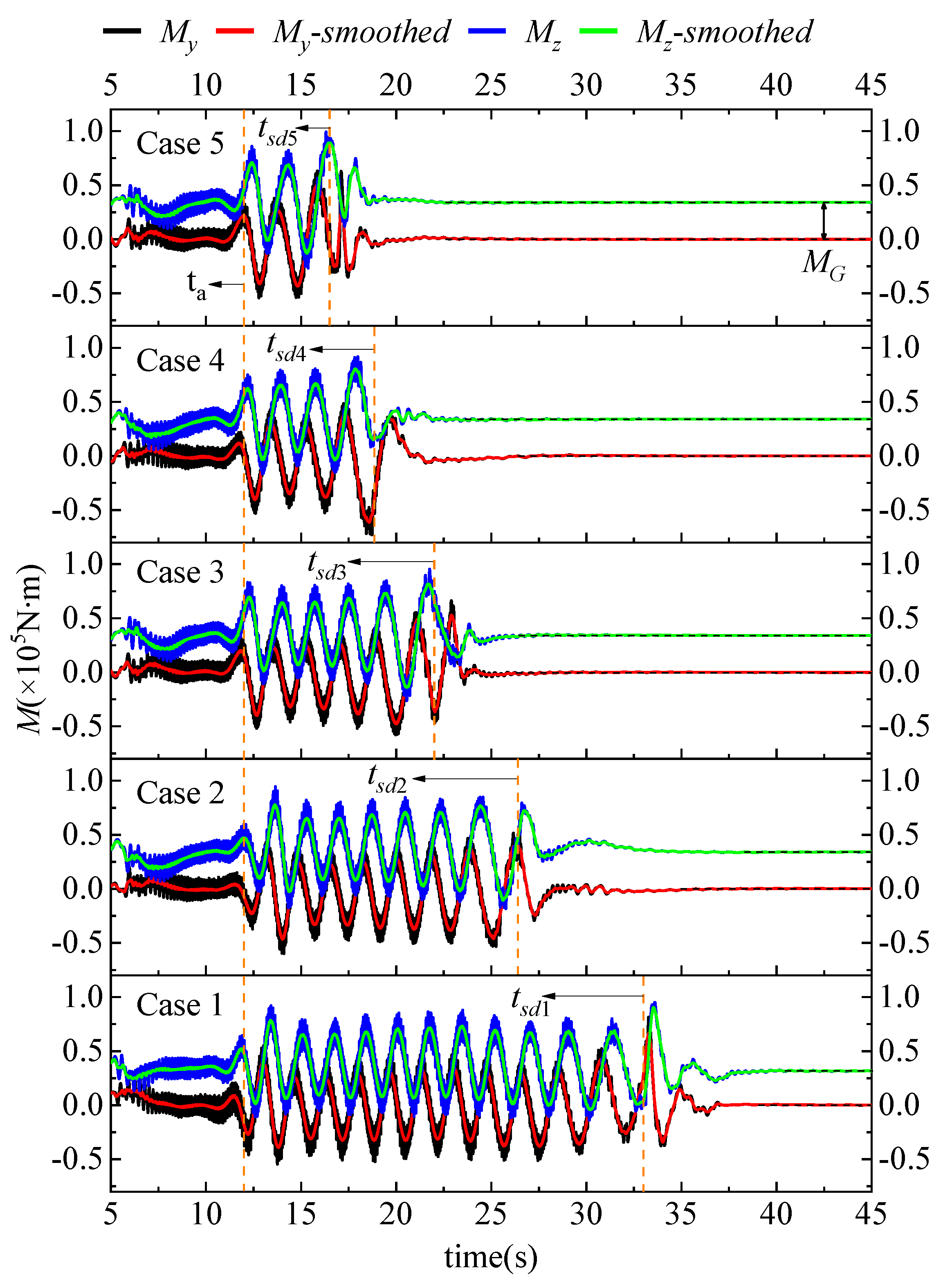
3.2. Comparison of Force and Moment Characteristics

To figure out the impact of water flow on the motion and deformation of the pump during shut-off conditions, the force and moment of the runner and SG were measured and are depicted in Figure 7. Hereafter, let us suppose that the pumping, braking, and turbine modes are Regions A, B, and C in each part. In Region A, the wave force at the SG port changes from positive to negative quickly; on top of that, a maximum value appears. This indicates that the flow direction at higher height changes firstly because of gravity and a reduction in runner speed. And the emerging reverse flow brings about great uncertainty in the SG. Following on, at the beginning of B, the decreasing hydraulic axial force and moment have rebounded, which is a result of the water hammer caused by reverse flow (Figure 7b). Immediately switching to Region C, the rotary reverse of the runner exacerbates the water hammer effect and causes a fluctuation period at D and G. In Region C, the maximum reverse flow contributes to a secondary hump in the SG wave force (Figure 7a). During Periods E and H, it can be seen that a secondary water hammer caused by flow increment (Figure 6c) incurs a short-term fluctuation in the axial force and moment of the runner after t a (Figure 7b). Obviously, the axial force and moment will not drop until the SG has nearly closed. The maximum axial forces and moments differ greatly and increase from Case 1 to Case 5, and those of Case 5 is 1.82 times those of Case 1. In Figure 7b, the axial component of gravity is presented as G x to distinguish the lifting phenomenon. As seen in Period F, severe lifting happens when the SG speed surpasses 15 m/min. Moreover, the faster the SG speed is, the more severe the lifting will be. From Figure 7c, it can be concluded that the direction of the axial moment is decided by the runner’s direction, as their intersection point on the 0-value line is coincident.
From the above external and force characteristic curves, we can observe an obvious correlation between SG speed and the maximum values of the performance parameters of turbine mode. Here, the determination coefficient (R2), root mean squared error (RSME) and mean absolute error (MAE) were applied to verify this assumption [52]. The expressions for the RSME and MAE performance metrics are listed as Equations (10) and (11).
MSE = 1 N i = 1 N ( Q 0 i Q 1 i ) 2
RMSE = 1 N i = 1 N ( Q 0 i Q 1 i ) 2
where Q0i is the extreme value of the CFD results for performance parameter i, Q1i is the fitting result of the linear fit calculation, and N is the number of parameters. According to Table 2, the R2 of each parameter is greater than 0.8; moreover, the MAE and RSME are almost completely below 1, proving that the characteristic parameters are directly affected by SG speed.
In order to explore the specific properties of the SAFP, the runner moments in two orthogonal-radial directions y and z (seen in Figure 1) were measured in this study, as exhibited in Figure 8. Conspicuous differences can be observed between My and Mz in the five cases. Before ta, the two moments fluctuate in only a small range. However, from ta on, regular fluctuations follow until tsd in each case. The total fluctuation time of Case 1 is 3.65 times that of Case 5. Additionally, in each case, the attraction difference MG between My and Mz was detected, indicating that gravity has a strong effect on the motion of the pump in the vertical direction, which results in an off-axis phenomenon in the vertical direction. This may lead to severe gear rotary eccentricity; more seriously, bearing wear and damage may happen [53].
To compare the off-axis intensity of the five cases, a peak intensity coefficient K ¯ was defined as shown in Equation (12), where β was used instead of the number of internal peaks and where the first and the last peak were excluded to improve the calculation accuracy. Ki is the value of each internal peak for the smoothed signal curve. The K ¯ of the five cases is shown in Figure 9. It is clear that K ¯ reaches its minimum in Case 4. This indicates that too slow or too rapid movement of the gate will bring about not only longer oscillations but also more severe amplitudes, which will lead to frequent fatigue damage to the shaft and eccentric motion wear of the bearings. Hence, the proper SG speed is fundamental to ease the off-axis effect of gear motion.
K ¯ = i = 2 n 1   K i β 2
To find out the intrinsic factor of the moment pulsation, the STFT method was applied to process the moment signals, as presented in Figure 10. Evidently, blade passing frequency (BPF) bands were found throughout the entire transient process, suggesting that the blade motion engenders the pulsation of runner moments. Extraordinarily, the moment pulsation intensity in the axial direction was not as strong as in the other two directions. From Figure 1, it can be concluded that the strong interaction between the impeller blades and the flow passage wall gives rise to the fluctuation of the runner in the radial direction; this interaction is much stronger than the axial one.

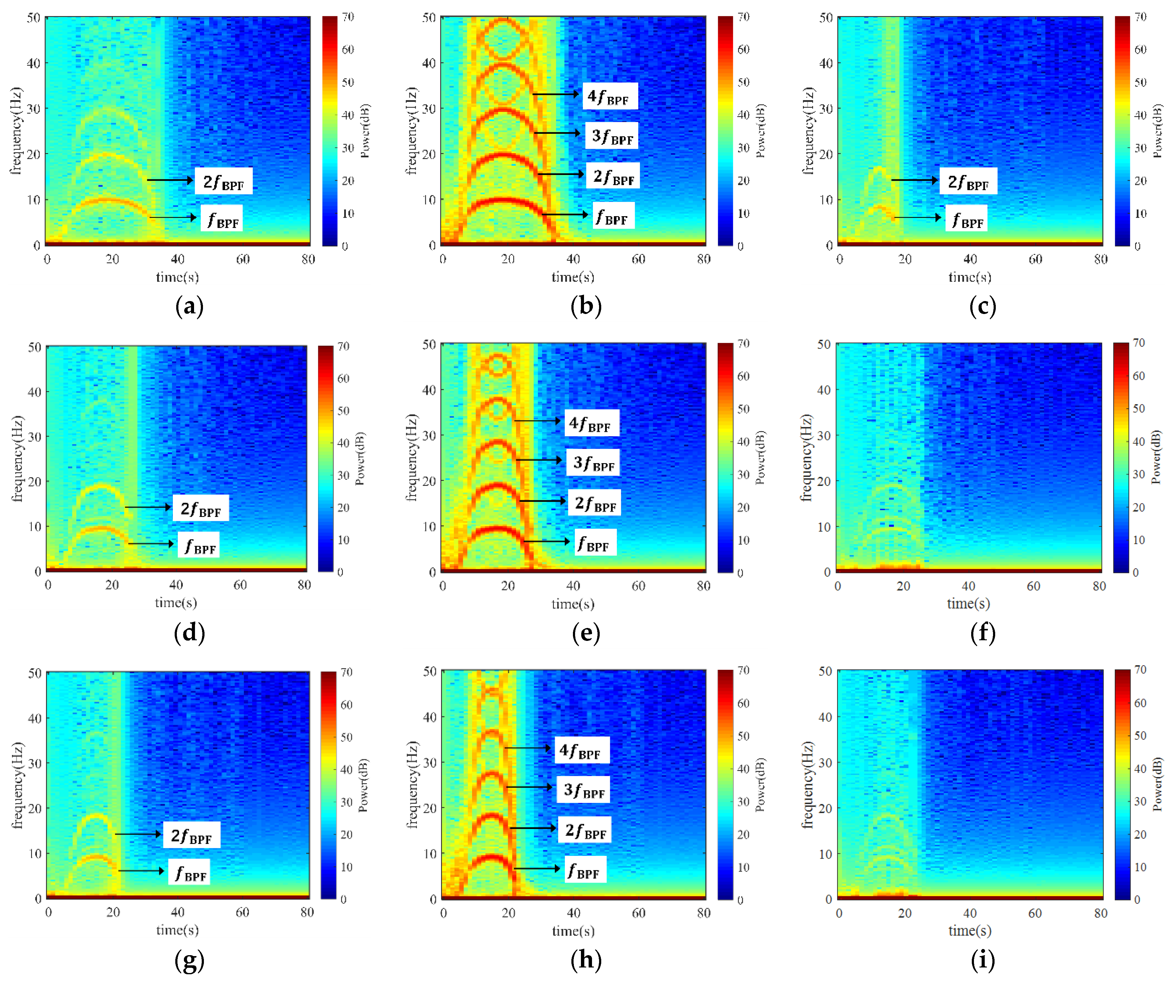
3.3. Comparison of Pressure Fluctuation Characteristics

To figure out the distribution of pressure fluctuation in the pump, three monitoring points were set before the runner in the inlet conduit (Point 1), between the impeller and guide vane (Point 2), and after the guide vane (Point 3), as shown in Figure 11. To elaborate on the development of pressure during the shut-off condition, the STFT method was applied to process the monitored signals, as depicted in Figure 12, where the five sets of results represent the five cases at the three locations. If we take Case 1 as an example (Figure 12a,c), noticeable BPF bands with high amplitude were captured at the three monitored positions. Among them, the signal magnitude at Point 2 was the strongest, Point 1 came second, and Point 3 was the last. If we compare the five cases, the width of the frequency bands narrowed from Case 1 to Case 5. Moreover, the maximum magnitudes at the three locations also dropped by 1.04, 1.03, and 1.26 times, respectively. Unambiguously, a faster SG shut-down time will not only result in longer oscillation time but also stronger oscillation intensity.

4. Conclusions

This article proposes a CFD-based approach with dynamic mesh and a high precision SAFP computational model, and reveals the effect of SG speed and a slanted structure on the shut-off performance. Five shut-off conditions with various SG shut-down speeds were modeled. Based on accurate external characteristic verification with a model pump, the results showed that the SG shut-down speed and the slanted structure had a significant effect on the performance of the SAFP. A faster SG shut-down speed leads to larger reverse maximum head, axial force, and axial moment due to a more severe water hammer effect, which is contrary to the maximum reverse flow rate and the runner speed. According to the comparison of the hydraulic axial force and gravity in the axial components, a serious lifting phenomenon happens when the SG speed exceeds 15 m/min and worsens as the SG speed increases. Compared with the axial moments, the radial moments present stronger harmonic fluctuations due to the stronger rotor–stator interaction. Specially, the fluctuation of the runner in the vertical direction presents an off-axis characteristic compared with the horizontal one due to the effect of gravity on the slanted structure. Moreover, the 17.5 m/min SG speed achieved the smallest off-axis intensity. According to the STFT analysis, the BPF led to the fluctuation at different locations in the pump, and the location closest to the impeller presented the largest oscillatory intensity.
This study introduces a useful approach for studying large-scale SAFPs in urban pump stations under SG shut-down conditions. The effects of SG speed and the slanted structure in large hydraulic fluid machinery were investigated, which can be adapted for optimization of the SAFP. In the future, simulation-derived correlation functions among SG speed, SAFP geometry, and operating parameters will be studied for a wide range of SAFP models.

Author Contributions

Conceptualization, modeling, methodology, and writing—original draft preparation, Z.Y.; methodology, project administration and writing—review and editing, Z.T.; project administration and data checking, Q.H. and Q.Y. All authors have read and agreed to the published version of the manuscript.

Funding

This work was supported by the National Natural Science Foundation of China (52075481), the Zhejiang Provincial Natural Science Foundation (LR19E050002), and the Major Science and Technology Program in Xiaoshan District, Zhejiang Province (2020112).

Institutional Review Board Statement

Not applicable.

Informed Consent Statement

Not applicable.

Data Availability Statement

Not applicable.

Conflicts of Interest

The authors declare no conflict of interest.

Nomenclature

FxAxial force in the x direction (N)
FgWave force at the gate port (N)
GxGravity in the axial component (N)
HHead of the prototype pump (m)
HMHead of the model pump (m)
JInertia moment of the runner (kg.m2)
KiValue of each internal peak (N∙m)
KPeak intensity coefficient of Mz (N∙m)
MfMechanical resistance moment (N∙m)
MGMoment caused by gravity (N∙m)
MhHydraulic moment (N∙m)
MxMoment in the x direction (N∙m)
MyMoment in the y direction (N∙m)
MzMoment in the z direction (N∙m)
nFlow rate of the prototype pump (rpm)
nMFlow rate of the model pump (rpm)
PShaft power of the prototype pump (W)
PMShaft power of the model pump (W)
QFlow rate of the prototype pump (m3/s)
QMFlow rate of the model pump (m3/s)
QrRated flow rate (m3/s)
taTime when water hammer intensifies
tQm1~tQm5Time at the maximum flow rate for Case 1 to Case 5 (s)
tsd1~tsd5Time when the gate shut down for Case 1 to Case 5 (s)
twm1~twm5Time at the maximum rotation speed for Case 1 to Case 5 (s)
wiRotation speed of the current time step (rad/s)
wi+1Rotation speed of next time step (rad/s)
βNumber of internal peaks of the MZ curve (-)
ρDensity of water (kg/m3)
λThe size ratio between the prototype pump and the model pump (-)
ΔTTime step size (s)

Abbreviations

1-DOne-dimensional
3-DThree-dimensional
BPFBlade passing frequency
CFDComputational fluid dynamics
MAEMean absolute error
R2Determination coefficient
RSMERoot mean square error
SGSluice gate
SAFPSlanted axial-flow pump
STFTShort-tern Fourier transformation
TKETurbulence kinetic energy

References

  1. Kandler, N.; Annus, I.; Vassiljev, A. Controlling peak runoff from plots by coupling street storage with distributed real time control. Urban Water J. 2022, 19, 97–108. [Google Scholar] [CrossRef]
  2. Truu, M.; Annus, I.; Roosimagi, J.; Kaendler, N.; Vassiljev, A.; Kaur, K. Integrated Decision Support System for Pluvial Flood-Resilient Spatial Planning in Urban Areas. Water 2021, 13, 3340. [Google Scholar] [CrossRef]
  3. Qiang, Y.; Zhang, L.; He, J.; Xiao, T.; Huang, H.; Wang, H. Urban flood analysis for Pearl River Delta cities using an equivalent drainage method upon combined rainfall-high tide-storm surge events. J. Hydrol. 2021, 597, 126293. [Google Scholar] [CrossRef]
  4. Zambrano, J.C.I.; Michavila, J.; Arenas Pinilla, E.; Diehl, J.C.; Ertsen, M.W. Water lifting water: A comprehensive spatiotemporal review on the hydro-powered water pumping technologies. Water 2019, 11, 1677. [Google Scholar] [CrossRef] [Green Version]
  5. Gopal, C.; Mohanraj, M.; Chandramohan, P.; Chandrasekar, P. Renewable energy source water pumping systems-A literature review. Renew. Sustain. Energy Rev. 2013, 25, 351–370. [Google Scholar] [CrossRef]
  6. Li, D.; Wang, H.; Qin, Y.; Wei, X.; Qin, D. Numerical simulation of hysteresis characteristic in the hump region of a pump-turbine model. Renew. Energy 2018, 115, 433–447. [Google Scholar] [CrossRef]
  7. Kan, K.; Zheng, Y.; Fu, S.; Liu, H.; Yang, C.; Zhang, X. Dynamic stress of impeller blade of shaft extension tubular pump device based on bidirectional fluid-structure interaction. J. Mech. Sci. Technol. 2017, 31, 1561–1568. [Google Scholar] [CrossRef]
  8. Pei, J.; Meng, F.; Li, Y.; Yuan, S.; Chen, J. Fluid-structure coupling analysis of deformation and stress in impeller of an axial-flow pump with two-way passage. Adv. Mech. Eng. 2016, 8, 1687814016646266. [Google Scholar] [CrossRef] [Green Version]
  9. Zhang, D.-S.; Shi, W.-D.; Chen, B.; Guan, X.-F. Unsteady flow analysis and experimental investigation of axial-flow pump. J. Hydrodyn. 2010, 22, 35–43. [Google Scholar] [CrossRef]
  10. Kang, C.; Yu, X.; Gong, W.; Li, C.; Huang, Q. Influence of stator vane number on performance of the axial-flow pump. J. Mech. Sci. Technol. 2015, 29, 2025–2034. [Google Scholar] [CrossRef]
  11. Yang, F.; Chang, P.; Hu, W.; Mao, B.; Liu, C.; Li, Z. Numerical study on pressure pulsation in a slanted axial-flow pump device under partial loads. Processes 2021, 9, 1404. [Google Scholar] [CrossRef]
  12. Wang, Z.; Peng, G.; Zhou, L.; Hu, D. Hydraulic performance of a large slanted axial-flow pump. Eng. Comput. 2010, 27, 243–256. [Google Scholar] [CrossRef]
  13. Yang, F.; Liu, C. Numerical and experimental investigation of slanted axial-flow pumping system. J. Eng. Sci. Technol. Rev. 2013, 6, 62–68. [Google Scholar] [CrossRef]
  14. Zhang, R.; Chen, H.-X. Numerical analysis of cavitation within slanted axial-flow pump. J. Hydrodyn. 2013, 25, 663–672. [Google Scholar] [CrossRef]
  15. Wang, C.; Wang, F.; Tang, Y.; Zi, D.; Xie, L.; He, C.; Zhu, Q.; Huang, C. Investigation into the phenomenon of flow deviation in the s-shaped discharge passage of a slanted axial-flow pumping system. J. Fluids Eng. Trans. ASME 2020, 142, 041205. [Google Scholar] [CrossRef]
  16. Liu, J.; Li, Z.; Wang, L.; Jiao, L. Numerical simulation of the transient flow in a radial flow pump during stopping period. J. Fluids Eng. Trans. ASME 2011, 133, 111101. [Google Scholar] [CrossRef]
  17. Fu, X.; Li, D.; Wang, H.; Zhang, G.; Li, Z.; Wei, X.; Qin, D. Energy analysis in a pump-turbine during the load rejection process. J. Fluids Eng. Trans. ASME 2018, 140, 101107. [Google Scholar] [CrossRef]
  18. Zeng, W.; Yang, J.; Hu, J.; Yang, J. Guide-Vane Closing Schemes for Pump-Turbines Based on Transient Characteristics in S-shaped Region. J. Fluids Eng. Trans. ASME 2016, 138, 051302. [Google Scholar] [CrossRef]
  19. Zhou, D.; Chen, H.; Zhang, L. Investigation of pumped storage hydropower power-off transient process using 3d numerical simulation based on sp-vof hybrid model. Energies 2018, 11, 1020. [Google Scholar] [CrossRef] [Green Version]
  20. Urbanowicz, K.; Bergant, A.; Kodura, A.; Kubrak, M.; Malesiska, A.; Bury, P.; Stosiak, M. Modeling transient pipe flow in plastic pipes with modified discrete bubble cavitation model. Energies 2021, 14, 6756. [Google Scholar] [CrossRef]
  21. Coronado-Hernandez, O.E.; Besharat, M.; Fuertes-Miquel, V.S.; Ramos, H.M. Effect of a commercial air valve on the rapid filling of a single pipeline: A numerical and experimental analysis. Water 2019, 11, 1814. [Google Scholar] [CrossRef] [Green Version]
  22. Tong, Z.-M.; Xin, J.-G.; Tong, S.-G.; Yang, Z.-Q.; Zhao, J.-Y.; Mao, J.-H. Internal flow structure, fault detection, and performance optimization of centrifugal pumps. J. Zhejiang Univ. Sci. A 2020, 21, 85–117. [Google Scholar] [CrossRef]
  23. Tong, Z.; Xin, J.; Ling, C. Many-Objective Hybrid Optimization method for impeller profile design of low specific speed centrifugal pump in district energy systems. Sustainability 2021, 13, 10537. [Google Scholar] [CrossRef]
  24. Fu, S.; Zheng, Y.; Kan, K.; Chen, H.; Han, X.; Liang, X.; Liu, H.; Tian, X. Numerical simulation and experimental study of transient characteristics in an axial flow pump during start-up. Renew. Energy 2020, 146, 1879–1887. [Google Scholar] [CrossRef]
  25. Han, L.; Wang, H.J.; Gao, Y.H.; Li, D.Y.; Gong, R.Z.; Wei, X.Z. Dynamic Simulation in Guide Vane Opening Process of a Pump-Turbine in Pump Mode. J. Appl. Fluid Mech. 2017, 10, 1441–1449. [Google Scholar] [CrossRef]
  26. Liu, Y.; Zhou, J.; Zhou, D. Transient flow analysis in axial-flow pump system during stoppage. Adv. Mech. Eng. 2017, 9, 1687814017723280. [Google Scholar] [CrossRef] [Green Version]
  27. Kan, K.; Chen, H.; Zheng, Y.; Zhou, D.; Binama, M.; Dai, J. Transient characteristics during power-off process in a shaft extension tubular pump by using a suitable numerical model. Renew. Energy 2021, 164, 109–121. [Google Scholar] [CrossRef]
  28. Li, D.; Wang, H.; Li, Z.; Nielsen, T.K.; Goyal, R.; Wei, X.; Qin, D. Transient characteristics during the closure of guide vanes in a pump turbine in pump mode. Renew. Energy 2018, 118, 973–983. [Google Scholar] [CrossRef]
  29. Wang, W.; Pavesi, G.; Pei, J.; Yuan, S. Transient simulation on closure of wicket gates in a high-head Francis-type reversible turbine operating in pump mode. Renew. Energy 2020, 145, 1817–1830. [Google Scholar] [CrossRef]
  30. Chen, H.; Zhou, D.; Zheng, Y.; Jiang, S.; Yu, A.; Guo, Y. Load rejection transient process simulation of a kaplan turbine model by co-adjusting guide vanes and runner blades. Energies 2018, 11, 3354. [Google Scholar] [CrossRef] [Green Version]
  31. Mao, X.; Dal Monte, A.; Benini, E.; Zheng, Y. Numerical study on the internal flow field of a reversible turbine during continuous guide vane closing. Energies 2017, 10, 988. [Google Scholar] [CrossRef]
  32. Cheng, Z.; Tong, S.; Tong, Z. Bi-directional nozzle control of multistage radial-inflow turbine for optimal part-load operation of compressed air energy storage. Energy Convers. Manag. 2019, 181, 485–500. [Google Scholar] [CrossRef]
  33. Sun, H.; Lv, Y.; Ni, J.; Jiang, X.; Wang, Z. Effect of seal locations of pump-turbine on axial hydraulic trust. J. Mar. Sci. Eng. 2021, 9, 623. [Google Scholar] [CrossRef]
  34. Fu, X.; Li, D.; Wang, H.; Zhang, G.; Li, Z.; Wei, X. Numerical simulationof the transient flowin a pump-turbine duringthe load rejection processwith special emphasison the cavitation effect. J. Fluids Eng. Trans. ASME 2020, 142, 011103. [Google Scholar] [CrossRef]
  35. Su, W.-T.; Li, X.-B.; Xia, Y.-X.; Liu, Q.-Z.; Binama, M.; Zhang, Y.-N. Pressure fluctuation characteristics of a model pump-turbine during runaway transient. Renew. Energy 2021, 163, 517–529. [Google Scholar] [CrossRef]
  36. Lu, J.; Qian, Z.; Lee, Y.-H. Numerical investigation of unsteady characteristics of a pump turbine under runaway condition. Renew. Energy 2021, 169, 905–924. [Google Scholar] [CrossRef]
  37. Kan, K.; Zheng, Y.; Chen, H.; Zhou, D.; Dai, J.; Binama, M.; Yu, A. Numerical simulation of transient flow in a shaft extension tubular pump unit during runaway process caused by power failure. Renew. Energy 2020, 154, 1153–1164. [Google Scholar] [CrossRef]
  38. Tong, Z.; Miao, J.; Tong, S.; Lu, Y. Early prediction of remaining useful life for Lithium-ion batteries based on a hybrid machine learning method. J. Clean. Prod. 2021, 317, 128265. [Google Scholar] [CrossRef]
  39. Tong, Z.; Cheng, Z.; Tong, S. Preliminary design of multistage radial turbines based on rotor loss characteristics under variable operating conditions. Energies 2019, 12, 2550. [Google Scholar] [CrossRef] [Green Version]
  40. Cui, H.C.; Fan, H.G.; Chen, N.X. Optimization of wicket-gate closing law considering different cases. In Proceedings of the 26th IAHR Symposium on Hydraulic Machinery and Systems, Beijing, China, 19–23 August 2012. [Google Scholar]
  41. Yao, Z.; Bi, H.L.; Huang, Q.S.; Li, Z.J.; Wang, Z.W. Analysis on influence of guide vanes closure laws of pump-turbine on load rejection transient process. In Proceedings of the 6th International Conference on Pumps and Fans with Compressors and Wind Turbines (ICPF), Beijing, China, 19–22 September 2013. [Google Scholar]
  42. Rezghi, A.; Riasi, A.; Tazraei, P. Multi-objective optimization of hydraulic transient condition in a pump-turbine hydropower considering the wicket-gates closing law and the surge tank position. Renew. Energy 2020, 148, 478–491. [Google Scholar] [CrossRef]
  43. Sun, Y.; Yu, G.; Liu, C. Research on closing control of the sluice gate for sudden power off of large pump. Adv. Sci. Lett. 2011, 4, 2316–2320. [Google Scholar] [CrossRef]
  44. Lee, B.-R.; Yun, T.-J.; Oh, W.-B.; Lee, C.-W.; Kim, H.-H.; Jeong, Y.-J.; Kim, I.-S. Study on floodgate resonance avoidance using FSI analyses. Trans. Korean Soc. Mech. Eng. A 2021, 45, 223–230. [Google Scholar] [CrossRef]
  45. Zhang, Q.; Tong, Z.; Tong, S.; Cheng, Z. Modeling and dynamic performance research on proton exchange membrane fuel cell system with hydrogen cycle and dead-ended anode. Energy 2021, 218, 119476. [Google Scholar] [CrossRef]
  46. Fu, X.; Li, D.; Wang, H.; Zhang, G.; Li, Z.; Wei, X. Influence of the clearance flow on the load rejection process in a pump-turbine. Renew. Energy 2018, 127, 310–321. [Google Scholar] [CrossRef]
  47. Ivanov, E.A.; Zharkovsky, A.A.; Borshchev, I.O.; Svoboda, D.G. Technique for axial pump characteristics predicting in CFD package OpenFOAM. In Oil and Gas Engineering; Myshlyavtsev, A.V., Likholobov, V.A., Yusha, V.L., Eds.; AIP Publishing: Melville, NY, USA, 2019; Volume 2141. [Google Scholar]
  48. Zhou, D.; Chen, H.; Zhang, J.; Jiang, S.; Gui, J.; Yang, C.; Yu, A. Numerical Study on Flow Characteristics in a Francis Turbine during Load Rejection. Energies 2019, 12, 716. [Google Scholar] [CrossRef] [Green Version]
  49. Tong, Z.; Chen, Y.; Tong, S.; Yu, Y.; Li, J.; Hao, G. Multi-objective optimization design of low specific speed centrifugal pumps based on NSGA-Ⅲ algorithm. China Mech. Eng. 2020, 31, 2239–2246. [Google Scholar]
  50. Chen, H.; Zhou, D.; Kan, K.; Guo, J.; Zheng, Y.; Binama, M.; Xu, Z.; Feng, J. Transient characteristics during the co-closing guide vanes and runner blades of a bulb turbine in load rejection process. Renew. Energy 2021, 165, 28–41. [Google Scholar] [CrossRef]
  51. Wang, C.; Wang, F.; Xie, L.; Wang, B.; Yao, Z.; Xiao, R. On the vortical characteristics of horn-like vortices in stator corner separation flow in an axial flow pump. J. Fluids Eng. Trans. ASME 2021, 143, 061201. [Google Scholar] [CrossRef]
  52. Burgan, H.I.; Aksoy, H. Daily flow duration curve model for ungauged intermittent subbasins of gauged rivers. J. Hydrol. 2022, 604, 127249. [Google Scholar] [CrossRef]
  53. Chen, Z.; Jiang, Y.; Li, S.; Tong, Z.; Tong, S.; Tang, N. Effect of lubricant viscosity on dynamics of high-precision gear considering lubricant-induced backlash reduction. Tribol. Int. 2022, 168, 107447. [Google Scholar] [CrossRef]
Figure 1. The schematic diagram of the pump system under shut-off conditions.
Energies 15 01905 g001
Figure 2. The grid model of the main calculation domains.
Energies 15 01905 g002
Figure 3. Test rig and variation of head and efficiency under steady-state conditions. (a) Test rig of the model pump. (b) Comparison of head and efficiency between the test and the simulation.
Energies 15 01905 g003
Figure 4. The allowable range of SG speed required by the pump station.
Energies 15 01905 g004
Figure 5. The cooperative control of the runner and SG during the calculation. The left and right sides represent the runner and SG control steps, respectively.
Energies 15 01905 g005
Figure 6. Variation in the hydraulic characteristic parameters during shut-off conditions of the five cases. (a) Head; (b) runner speed; (c) flow rate.
Energies 15 01905 g006
Figure 7. The variation in the hydraulic force and moment parameters during shut-off conditions in the five cases. (a) Wave force at the SG port; (b) axial force of impeller; (c) axial moment of the impeller.
Energies 15 01905 g007
Figure 8. The moment in the y direction and z direction in the five cases.
Energies 15 01905 g008
Figure 9. Comparison of K ¯ in the five cases.
Energies 15 01905 g009
Figure 10. STFT of runner moment in three orthogonal directions x, y, and z. (a) Axial moment in the x direction; (b) diagonal-radial moment in the y direction; (c) horizontal-radial moment in the z direction.
Energies 15 01905 g010
Figure 11. Distribution of the three monitoring points.
Energies 15 01905 g011
Figure 12. STFT of pressure at the three monitoring points in the five cases. (a) Point 1 of Case 1; (b) Point 2 of Case 1; (c) Point 3 of Case 1; (d) Point 1 of Case 2; (e) Point 2 of Case 2; (f) Point 3 of Case 2; (g) Point 1 of Case 3; (h) Point 2 of Case 3; (i) Point 3 of Case 3; (j) Point 1 of Case 4; (k) Point 2 of Case 4; (l) Point 3 of Case 4; (m) Point 1 of Case 5; (n) Point 2 of Case 5; (o) Point 3 of Case 5.
Energies 15 01905 g012aEnergies 15 01905 g012b
Table 1. Mesh schemes and corresponding external characteristics.
Mesh SchemeTotal ElementsHead (m)
13,856,2615.59
25,173,9235.67
36,956,9735.73
49,046,9735.76
512,037,2485.77
Table 2. Performance matrix of typical parameters in the five cases.
Parameter NamePerformance Metrics
R2MAERSME
The maximum reverse flowrate0.800.70.88
The maximum reverse runner speed0.920.150.18
The maximum reverse head0.950.330.46
The maximum reverse axial force0.930.941.06
The maximum wave force at the gate port0.850.140.15
The maximum reverse axial moment0.900.700.88
Publisher’s Note: MDPI stays neutral with regard to jurisdictional claims in published maps and institutional affiliations.

