Article

Stable Crack Propagation Model of Rock Based on Crack Strain

1
Key Laboratory of Ministry of Education for Geomechanics and Embankment Engineering, Hohai University, Nanjing 210024, China
2
Research Institute of Geotechnical Engineering, Hohai University, Nanjing 210024, China
3
School of Earth Sciences and Engineering, Hohai University, Nanjing 211100, China
*
Author to whom correspondence should be addressed.
Energies 2022, 15(5), 1885; https://doi.org/10.3390/en15051885
Submission received: 25 January 2022 / Revised: 22 February 2022 / Accepted: 2 March 2022 / Published: 3 March 2022
(This article belongs to the Collection State of the Art Geo-Energy Technology in China)

Abstract

:
The establishment of a rock constitutive model considering microcrack propagation characteristics is an important channel to reflect the progressive damage and failure of rocks. The prepeak crack strain evolution curve of rock is divided into three stages based on the triaxial compression test results of granite and the definition of crack strain. According to the nonlinear variation characteristics of crack strain in the stage of rock crack stable propagation, rock deformation is expressed as the sum of matrix strain and crack strain. Then, the exponential constitutive relationship of rock crack stable propagation is deduced. The axial crack strains of the rock sample and its longitudinal section are equal. Thus, the longitudinal symmetry plane of the rock sample is abstracted as a model containing sliding crack structure in an elastic body, and the evolution equation of crack geometric parameters in the process of stable crack propagation is obtained. Compared with the experimental data, results show that the rock crack stable propagation model based on crack strain can adequately describe the evolution law of crack strain and wing crack length. In addition, the wing crack propagates easily when the elastic body with small width contains an initial crack with a large length and an axial dip angle of 45° under compressive load. This study provides a new idea for the analysis of the stable propagation characteristics and laws of rock cracks under compressive load.

1. Introduction

The damage and failure of rock mass are closely related to the evolution behavior of cracks. For many rock engineering disasters, such as rock burst in deep tunnels, splitting of high sidewalls of large caverns, and coal/water outburst in mining engineering, the key to exploring their mesoforming mechanism is to understand the propagation and evolution process of microcracks [1,2,3]. However, the fracture combination of natural rock mass is complex and changeable, and the expansion and penetration path under load cannot be determined easily; thus, the study of mesoscopic damage and fracture of rock mass has always been a popular and difficult issue in rock mechanics [4]. In recent years, acoustic emission (AE) and other methods have effectively identified the evolution characteristics of cracks in loaded rock samples [5,6]. The corresponding relationship between the evolution process of cracks in rocks and the stress–strain curve of rocks has been also clarified. Therefore, the establishment of a rock stress–strain constitutive model considering microcrack propagation is an important channel to reflect progressive damage and rock failure. This approach is essential to understand the crack evolution law and construct rock engineering disaster assessment and warning systems.
The deformation and failure of rocks result from closure, initiation, propagation, and coalescence of the internal cracks under the action of external load. Theoretical studies related to cracking processes can be broadly classified into three categories [7,8,9,10], namely, development and verification of crack initiation criteria, studies based on analytical methods, and studies based on numerical methods. The effects of loading conditions, sample boundary size, crack geometric characteristics, crack angle, crack number, and crack surface mechanical parameters on crack phenomena and crack patterns on rock samples were observed and studied through a large number of laboratory and numerical tests [11,12,13,14,15,16]. The effects of off-notch location on the crack initiation and propagation behaviors were examined by in situ observation, which indicated that the strength, failure patterns, and deformation properties of the rocks containing the pre-existing flaws evidently depended on the crack evolution [17]. Lee et al. [18] carried out a numerical simulation for the coalescence characteristics in Hwangdeung granite containing two unparallel fissures by using PFC2D, and the simulated peak strength, crack initiation stress and ultimate failure mode of Hwangdeung granite were compared with the experimental results. Martin proposed the definition of crack strain [19,20] to describe the crack size quantitatively and provided a method to determine the damage stress based on the inflection point of volume crack strain. Cai et al. [21] proposed a generalized crack initiation stress and crack damage stress threshold of rock mass according to crack strain.
The existence of initial cracks in hard and brittle rocks and the evolution of crack propagation during loading have an important influence on the stress–strain relationship of rocks. Liu et al. [22] and Zhao et al. [23] proposed the stress–strain relationship of porous rock under different stress states by using the double-strain Hooke law. Li et al. [24] theoretically analyzed the macro stress–strain relationship of rocks caused by crack propagation based on the airfoil crack model assuming crack angle. Zhang et al. [25] abstracted brittle rock as fracture material and skeleton material. They also established a constitutive model of brittle rock by considering initial void closure and its influence. Zuo et al. [26] regarded rock matrix and porous materials as “hard part” and “soft part” and proposed axial crack closure model and axial crack propagation model.
Mesoscopic damage and macroscopic deformation failure caused by crack evolution in rocks have been widely studied, mainly because of the randomness of crack distribution and uncertainty of evolution. However, the crack strain ignores the complex distribution shape of the crack and only considers the overall macrodeformation of the crack, effectively avoiding the difficulties caused by this uncertainty [27,28]. Based on the axial crack strain, the prepeak crack evolution behavior and its propagation model of rock have been preliminarily studied. However, the crack propagation in the model starts from the yield damage of rocks. The crack has been generated and propagated slowly and stably before the differential stress reaches the yield damage stress. When AE/microseismic technology is used to monitor the damage degree of rock mass in the actual rock engineering site to evaluate the stability of surrounding rock [29], the crack characteristics in the stable crack propagation stage before the yield damage (long-term strength) of surrounding rock must be mastered. Therefore, studying the stable propagation characteristics and laws of rock cracks under compressive load is necessary.
Given the above knowledge, the evolution characteristics of crack strain in the process of rock deformation and failure are analyzed in this study based on the stress–strain curve data of typical granite peaks. A rock crack stable propagation constitutive model was also established based on axial crack strain. This model was verified by comparing the results with the experimental data. Based on the principle that the axial crack strains of a rock sample and its longitudinal plane are equal, the equation describing the variation of crack geometric parameters in the process of stable crack propagation of rock sample is deduced, and the law of stable crack propagation is revealed.

2. Constitutive Model of Rock Crack Stable Propagation Based on Axial Crack Strain

Spatial AE for real-time positioning combined with stress–strain relationship is commonly used to describe the evolution process of crack damage during rock deformation [30,31]. Figure 1 shows the stage characteristics and stress levels at key points of the prepeak deformation process of granite. In general, the prepeak stress–strain curve of rocks can be divided into four stages, namely, crack closure stage, linear elastic deformation stage, stable crack propagation stage, and unstable crack propagation stage. The characteristic stresses corresponding to different stages are crack closure stress σcc, crack initiation stress σci, crack damage stress σcd, and peak stress σc. The crack initiation stress level is the beginning of crack initiation and stable propagation, accompanied by AE events. The crack damage stress level indicates the beginning of unstable crack propagation, which is usually determined by the inflection point of volume strain. In addition, the crack in the rock may close under hydrostatic pressure when the confining pressure is sufficiently large. Thus, the differential stress–strain curve has no crack closure stage.

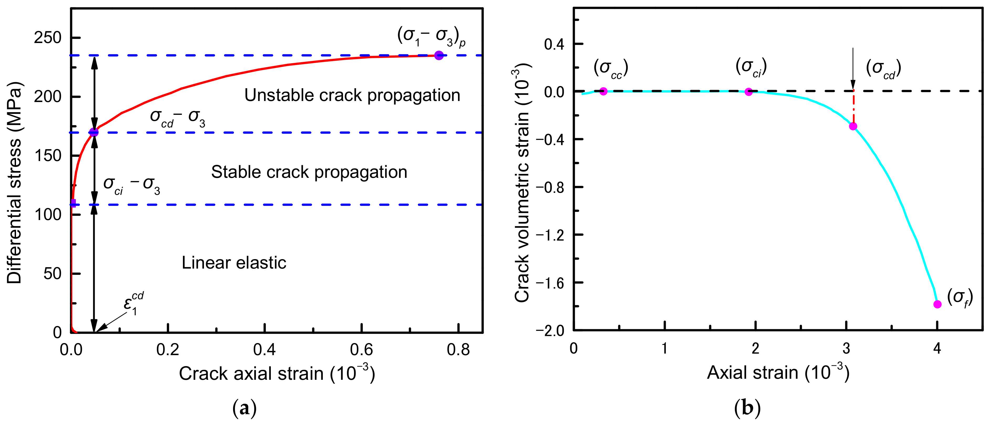
2.1. Evolution Characteristics of Prepeak Crack in the Rock

The closure, initiation, propagation, and coalescence of internal cracks in rocks under compressive load cause rock deformation. The crack strain represents the rock deformation caused by the crack or the deformation of the cracked body, and its value is equal to the total measured strain minus the elastic strain of the rock. The crack strain ignores the complicated distribution patterns of the crack in the rock deformation process and directly represents the total macrodeformation of cracks, which can quantitatively describe the characteristics of crack evolution. Under conventional triaxial compression, the crack strain [19] can be expressed as follows:
ε 1 c = ε 1 1 E σ 1 2 μ σ 3
ε v c = ε v 1 2 μ E σ 1 + 2 σ 3
where ε 1 c and ε v c   represent axial crack strain and volumetric crack strain, respectively; ε1 and εv are axial strain and volumetric strain, respectively; σ1 and σ3 represent axial stress and lateral stress, respectively; E and μ are the elastic modulus and Poisson’s ratio at the linear elastic stage, respectively.
This section analyzes the variation law of crack strain based on the triaxial compression test data of typical rock to describe the prepeak crack evolution characteristics of the rock. The triaxial test rock samples were taken from fine-grained granite with a buried depth of 450–460 m, mainly composed of plagioclase, quartz, alkaline feldspar, and biotite. Figure 2 shows the prepeak stress–strain curve of granite under different confining pressures. The increase in confining pressures increases the peak strength, elastic modulus, and peak strain of granite, and the initial compaction stage almost does not appear. According to the definition of crack strain in Equations (1) and (2), the variation trend of crack strain before granite peak under 10 MPa confining pressure is calculated and plotted, as shown in Figure 3. Under confining pressure, the prepeak differential stress–axial crack strain curve can be roughly divided into three stages, namely, linear elastic stage, stable crack growth stage, and unstable crack growth stage. First, the increase in the differential stress makes the axial crack strain nearly equal to 0, indicating that the cracks in the rock are closed. Second, the axial crack strain increases when the differential stress increases to the effective crack initiation stress (σciσ3). However, the rate of increase is slow, indicating that the crack initiation and propagation in the rock are stable. The axial crack strain increases at a fast rate when the differential stress reaches the effective crack damage stress (σcdσ3), indicating that the crack is in a state of unstable propagation. The variation trend of crack volumetric strain can also reflect the evolution characteristics of cracks in the rock. The variation law of crack volume strain is similar to that of axial crack strain, which is not explained further.

2.2. Constitutive Model of Stable Crack Propagation

Rock is a natural heterogeneous material. Its physical composition includes hard materials, such as rock grain skeleton, and soft materials, such as a large number of cracks or pores. Therefore, the macroscopic deformation of rock can be expressed as the sum of matrix strain and crack strain [22], as shown in Figure 4. The crack body is assumed as a unique material with its own physical and mechanical properties to reflect reasonably the deformation in the mechanical properties of soft and hard materials, and its deformation can be described by natural strain [32]. In comparison, the rock matrix is an elastic material, and its deformation is described by engineering strain. On the basis of this idea, Zuo studied the stress–strain relationship model of the prepeak crack closure stage and the unstable crack propagation stage [26] and regarded the stable crack propagation stage as the linear elastic stage. However, the crack strain changes nonlinearly during the stable crack propagation in rock, as shown in the above section. On the basis of the above ideas, a model of stable axial crack propagation in front of rock peak is attempted to be established in this section.
The natural strain is the ratio of the absolute deformation to the existing size of the sample, which is suitable for describing the deformation of soft matter. If the compression direction is positive and the tensile direction is negative, then the strain of the crack body during stable propagation is as follows:
d ε 1 c = dh c h c
where hc is the equivalent height of crack in the process of stable crack propagation.
The crack propagation in the rock is stable when the differential stress is between the effective crack initiation stress (σciσ3) and effective crack damage stress (σcdσ3). In this study, the effective differential stress (σe) is defined, that is, the differential stress minus the effective crack initiation stress, as expressed in Equation (4). A uniformly distributed force is imposed on the surface of the rock specimen (including cracks and the matrix). Therefore, the stress on the crack body in the process of stable crack propagation is the effective differential stress σe.
σ e = σ 1 σ 3 σ ci σ 3
d σ e = E c   d ε 1 c
where Ec is the equivalent elastic modulus of the crack body.
The substitution of Equation (3) into Equation (5) and their integration obtain σe.
σ e = E c   ln h c + C
where C is the integration constant.
Cracks in the rock begin to crack when the differential stress reaches the effective crack initiation stress. Therefore, the crack initiation conditions can be obtained as follows: σe = 0, hc = Hci ≈ 0. Hci is the equivalent crack height at the moment of crack initiation in rock. However, this condition makes Equation (6) mathematically meaningless. Assuming that the equivalent height of the crack is Hcd, the crack damage conditions can be obtained as follows: σe = σcdσci, hc = Hcd. The integral constant C can be obtained by substituting this condition into Equation (6).
C = σ cd σ ci E c   ln H cd
hc can be obtained by substituting Equation (7) into Equation (6).
h c = H cd   exp σ e σ cd σ ci E c
Based on Equation (8), the relationship between axial crack strain and effective differential stress of the crack body at the stage of stable crack propagation can be obtained.
ε 1 c = H cd H   exp σ e σ cd σ ci E c
where H is the height of the rock sample.
The stress–strain relationship model at the stage of steady crack growth can be obtained by replacing Hcd/H with ε 1 cd and substituting Equation (4) into Equation (9).
ε 1 c = ε 1 cd   exp σ 1 σ cd E c
where ε 1 cd is the axial crack strain of rock under yield damage.
The relation between stress and axial strain can be obtained by substituting Equation (10) into Equation (1) in the stable crack propagation stage (σci < σ1 < σcd).
ε 1 = ε 1 cd   exp σ 1 σ cd E c + 1 E σ 1 2 μ σ 3

2.3. Model Validation

The stable crack propagation growth model is verified by the test data, as shown in Figure 5. The test data were taken from the stable crack propagation stage of the typical granite stress–strain curve (Figure 2). By using the definition of crack strain, the test data of differential stress–axial crack strain and axial stress–axial strain of granite under different confining pressures can be obtained. From Equations (10) and (11), combined with relevant fitting parameters, the corresponding theoretical curve can be drawn. Figure 5a shows that the stable crack growth model is highly consistent with the test data of differential stress–axial crack strain, and the model can well describe the nonlinear evolution characteristics of crack strain in the stable crack growth stage before the rock peak. The stress–strain constitutive relation curve obtained based on this model at the stage of stable crack growth also coincides well with the test data, verifying the correctness of the model again, as shown in Figure 5b. The relevant fitting parameters are shown in Table 1.
The evolution starting point of axial crack strain shown in Figure 5a is not zero because a certain number of wing cracks are generated at the moment of crack initiation under low confining pressure. The axial crack strain at the moment of crack initiation in rock is denoted as ε 1 ci , and its theoretical value can be obtained by substituting σ 1 = σ ci into Equation (10). ε 1 ci is related to the confining pressure, and the model parameters ε 1 cd and Ec are affected by the confining pressure.
The effects of low confining pressure σ3 (0–10 MPa) on the damage axial crack strain ε 1 cd , crack equivalent elastic modulus Ec, and instantaneous crack initiation axial crack strain ε 1 ci are shown in Figure 6. The equivalent elastic modulus Ec of crack increases with the increase in confining pressure, whereas the damage axial crack strain ε 1 cd and the instantaneous crack initiation axial crack strain ε 1 ci show a decreasing trend. Compared with no confining pressure, the confining pressure of 10 MPa increased Ec by 31.8%, whereas ε 1 cd and ε 1 ci decreased by 54.6% and 71.7%, respectively. These results indicate that confining pressure has an obvious inhibition effect on crack initiation and stable propagation.

3. Evolution Model of Crack Geometric Parameters in the Process of Stable Crack Propagation in Rock

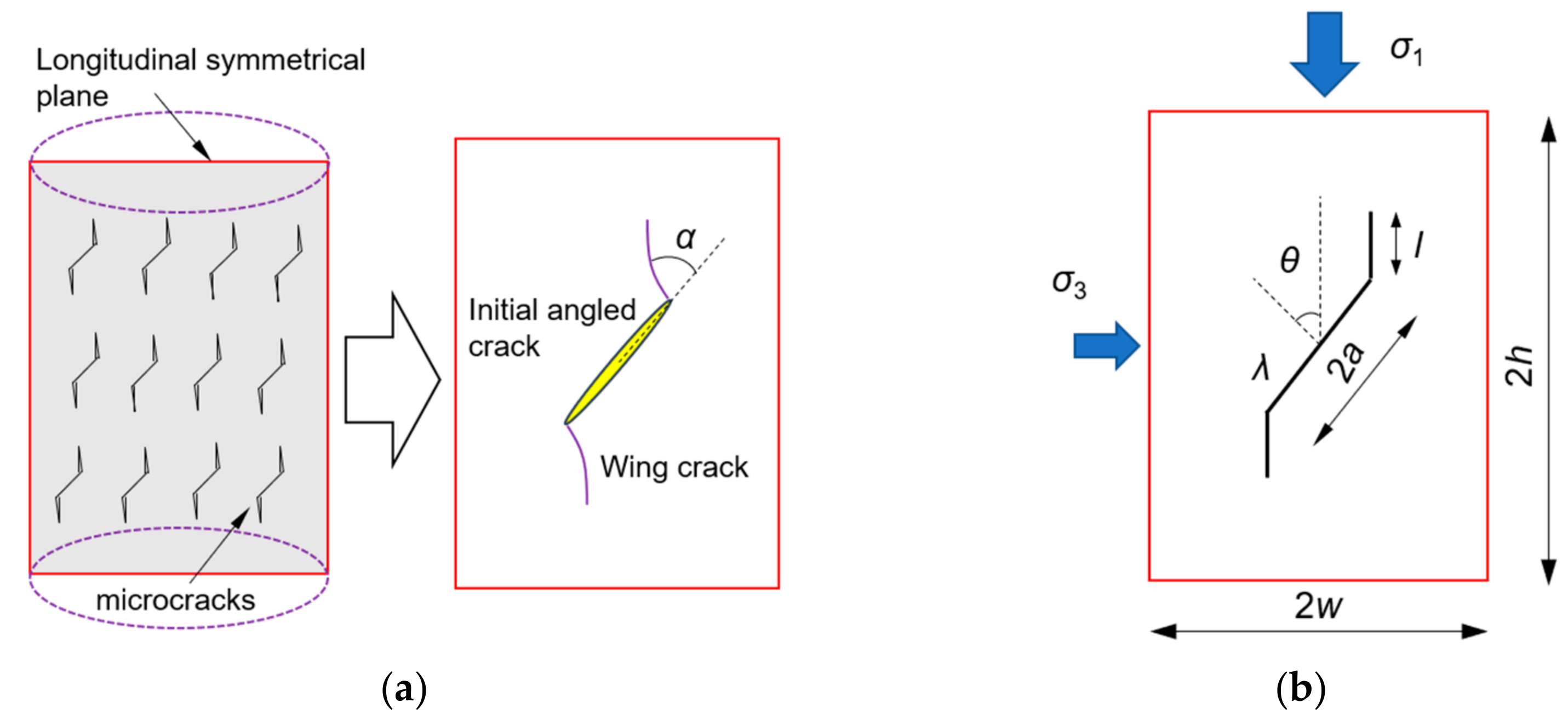
3.1. Mechanical Model of Structures with Cracks

New cracks begin to sprout in the rock when the axial stress reaches the crack initiation stress σci. A large number of microscopic observation test results [33,34] show that the new cracks generated at the end of the initial crack are tensile cracks. Most of them are consistent with the direction of the maximum compressive stress, and the new cracks only expand to some extent under a given stress increment. On the basis of this finding, some scholars proposed a two-dimensional plane strain model with crack structure and performed mechanical analysis. If the rock sample is considered an assembly of extremely thin longitudinal sections, the axial crack strain of the rock sample is equal to the axial crack strain of each longitudinal section. Therefore, the longitudinal plane of symmetry of the rock sample is abstracted as a model containing a sliding crack structure in an elastic body. An equation that can characterize the change of crack geometric parameters (wing crack length) during the stable crack propagation process of the rock sample can be obtained by calculating the axial crack strain and combining this calculation with the formula of the axial crack strain of the rock sample proposed above.
No interaction exists between microcracks at the stage of stable crack propagation. Each microcrack extends along different propagation paths until the axial stress reaches the crack damage stress σcd, and the intersection and penetration occur between them. Therefore, the deformation caused by each microcrack in the longitudinal symmetry plane of the rock sample in the process of stable expansion is superimposed as equivalent to the impact of a single crack structure on the rock, as shown in Figure 7a. Some scholars proposed an actual sliding crack model with a curved wing crack, but the stress intensity factor solution of this structure has no analytical form [35]. Therefore, the sliding crack model with straight axial wing crack is often adopted, as shown in Figure 7b, and this structure is confirmed to be an effective approximation in the analysis [36].

3.2. Evolution Equation of Crack Geometric Parameters

In the two-dimensional plane strain mechanical model shown in Figure 7b, the length of the elastic body is 2w, the height is 2h, the sliding crack with half-length a is at an angle θ with the horizontal plane, and the initial length of the wing crack is l. They are subjected to axial and lateral compressive stresses σ1 and σ3 and resist sliding through friction. The stress intensity factor solution for this structure [21] is as follows:
K I = 2 a τ cos θ π l σ 3 π l
where KI is the I-type stress intensity factor at the crack tip. When KI = KIC, the crack begins to grow stably; KIC is the fracture toughness of the rock. τ is the driving shear stress, which is expressed as follows:
τ = 1 2 σ 1 σ 3 sin 2 θ λ [ σ 1 + σ 3 + ( σ 1 σ 3 ) cos 2 θ ]
where λ is the coefficient of friction.
The axial displacement of the model is the sum of the axial displacement caused by the applied stress in the noncracked body and the axial displacement caused by the sliding crack. The axial displacement caused by sliding cracks can be derived from elastic strain energy, and the derivation process can be referred to in Reference [37]. The effective axial strain of the crack under the applied load is finally obtained by dividing the axial displacement by the height of the model.
ε 1 c = 2 a sin θ 1 μ 2 Ewh π τ a 4 cos θ + 2 a τ cos θ π ln l a σ 3 l a
where E is Young’s modulus, and μ is Poisson’s ratio.
The stress–strain curves of the crack body are obtained by abstracting the rock sample and its longitudinal symmetry plane into a matrix–crack composite model and an elastomer–slip crack structure model, respectively, i.e., Equations (10) and (14). The evolution equation with the geometric parameters of the crack in the stable crack propagation stage (σci < σ1 < σcd) under low confining pressure can be obtained by combining the two models.
ε 1 cd exp σ 1 σ cd E c = 2 a sin θ 1 μ 2 Ewh π τ a 4 cos θ + 2 a τ cos θ π ln l a σ 3 l a

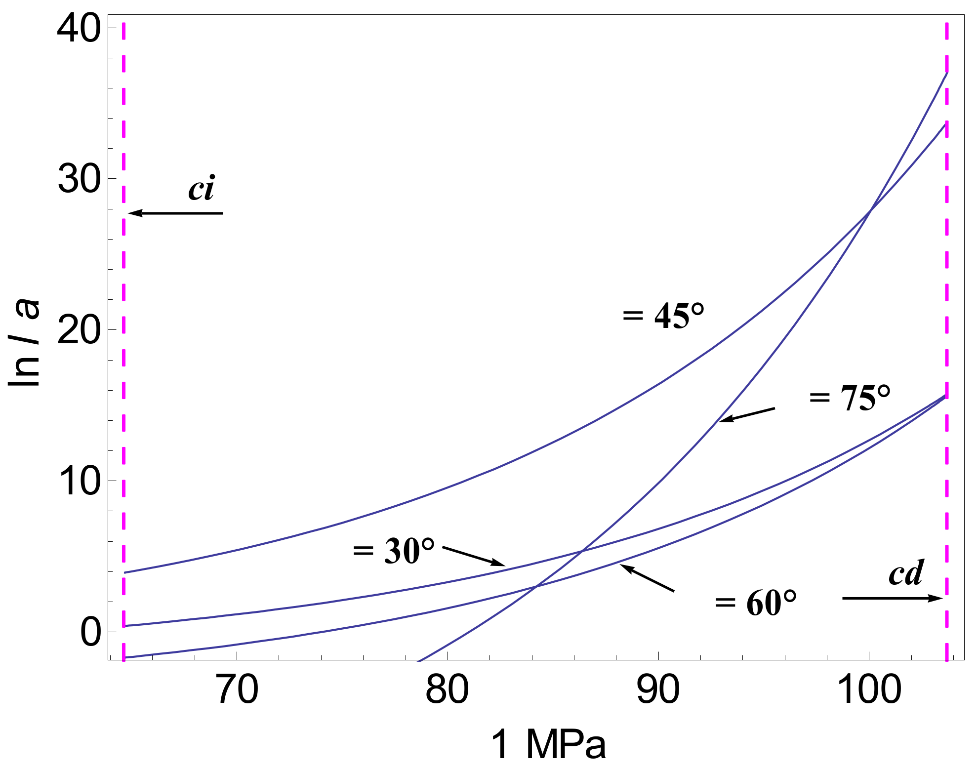
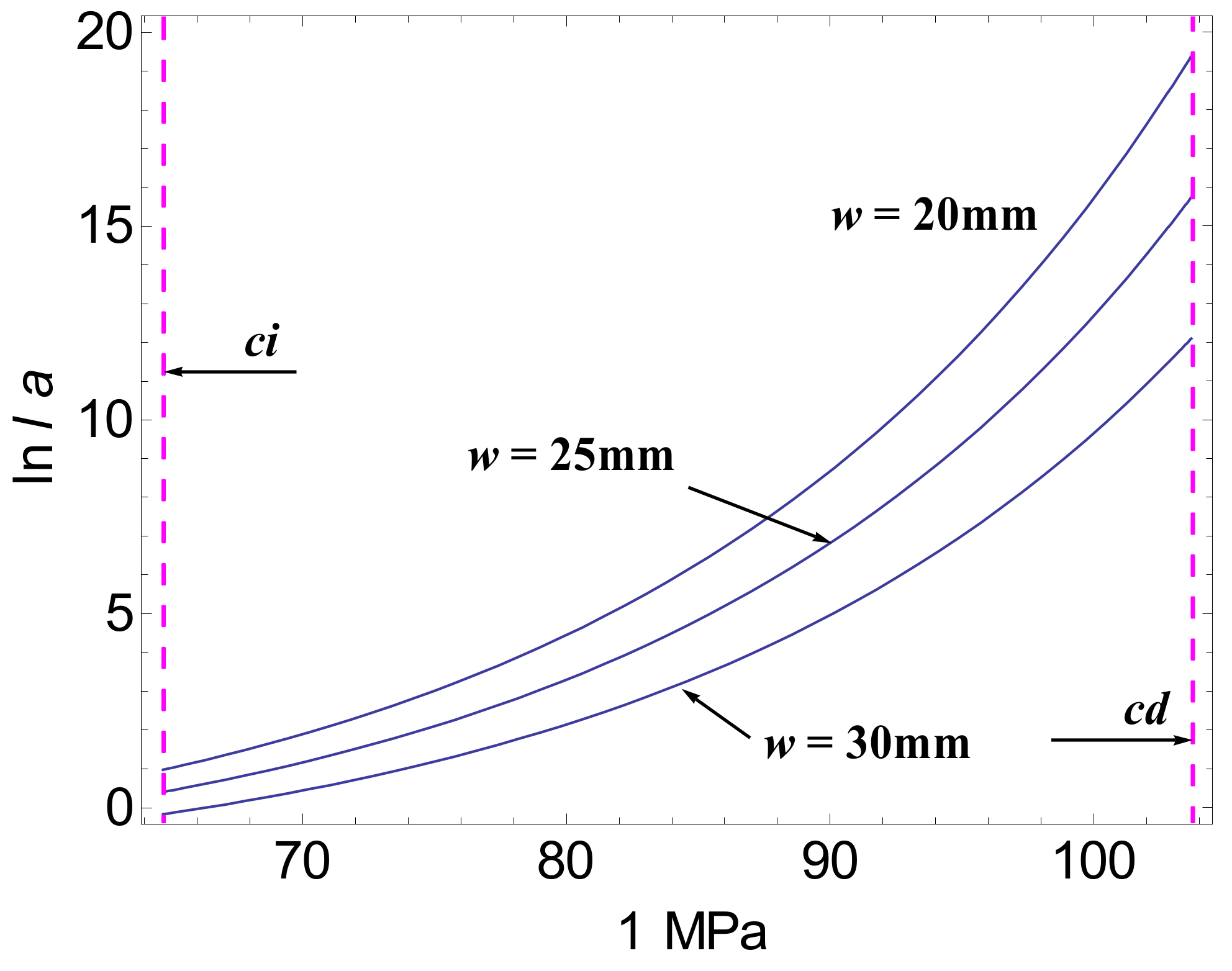
3.3. Evolution of Wing Crack Length in the Stage of Stable Crack Propagation

The relevant parameters in the evolution equation of geometric parameters with cracks in the stable crack propagation stage (σci < σ1 < σcd) of rock are assigned, the variation law of wing crack length with axial stress is analyzed, and the influence of some parameters on it is discussed. The related parameters are assigned as follows: the height of the elastic body with sliding crack structure 2h = 100 mm and its mechanical parameters (E, μ) are the same as those of the rock sample at the linear elastic stage, and λ = 0.3 is the friction coefficient between initial cracks. Other related parameters are shown in Table 1. The effects of the initial crack inclination angle θ and the elastic half-width w on the evolution of the wing crack length with the axial stress are analyzed and compared with the experimental results by taking the case without confining pressure as an example. The effect of the initial crack half-length a on the wing crack growth is also discussed.
Figure 8 and Figure 9 show the growth of wing crack length with axial stress under different initial crack inclination angles θ and different model half-widths w, respectively. In the stable crack growth stage, the wing crack length increases slowly at first, and then the increasing rate increases continuously. When the initial crack inclination angle is 45°, the wing crack tends to expand. Cracks in the narrow elastic body spread easily. The results of the progressive compression test of a prefabricated single crack in PMMA plates carried out by Ashy [36] showed that the cracks grow much more easily in narrow samples and cracks which lie near 45° to the compression axis grow most easily, though all those in the range 30 < θ< 60 nucleated wings at nearly the same stress. These results are consistent with the results of the test carried out by Ashy, which verified the correctness of the geometric parameter equation with cracks in the stable crack propagation stage proposed in this study.
The initial crack length a also has an important influence on the wing crack growth, as shown in Figure 10. The increase in the initial crack length simplifies wing crack propagation. The longer the initial crack is, the larger the total length of the compacted cracks in the rock is, or the greater the number of microcracks is. The new cracks may be initiated under a low axial compression.

4. Conclusions

The evolution characteristics of crack strain before peak are analyzed in this study based on the triaxial compression test results of typical granite and the definition of crack strain. On this basis, the constitutive relationship of stable crack propagation and the evolution equation of crack geometric parameters are derived by abstracting the rock sample and its longitudinal symmetry plane into a matrix–crack composite model and an elastomer–slip crack structure model, respectively. Moreover, the law of stable crack propagation is revealed. The main conclusions are listed below.
(1)
The prepeak differential stress–axial/volume crack strain curve of granite can be roughly divided into three stages: linear elastic stage (crack strain is approximately 0), stable crack growth stage (nonlinear change with slow crack strain growth), and unstable crack growth stage (nonlinear change with fast crack strain growth).
(2)
The exponential constitutive relation of rock crack stable propagation derived from the matrix–crack composite model can thoroughly describe the nonlinear evolution characteristics of crack strain in the stage of stable crack propagation.
(3)
Based on the principle that the axial crack strain of the rock sample and its longitudinal section are equal, the equation of the change of crack geometric parameters in the process of rock crack stable propagation can well reflect the evolution law of wing crack length.
(4)
The crack equivalent elastic modulus increases with the increase in confining pressure, whereas the damage axial crack strain and the instantaneous crack initiation axial crack strain show a decreasing trend. The initial crack inclination angle is 45°, the elastomer width is small, the initial crack length is large, and the wing crack is easy to expand.
(5)
The stable crack propagation model of rock based on axial crack strain supplements the neglect of the stable crack growth stage in previous studies and can semiquantitatively describe the evolution law of crack strain and wing crack length with fewer parameters. By embedding the proposed model into numerical software, more extensive studies on crack stable propagation can be carried out in the future.

Author Contributions

Conceptualization, X.H. and H.R.; funding acquisition, C.S.; investigation, X.H.; software, X.H. and C.S.; supervision, H.R.; validation, X.H.; visualization, X.H.; writing—original draft, X.H.; writing—review and editing, X.H., Y.Z. and W.Z. All authors have read and agreed to the published version of the manuscript.

Funding

The work presented in this paper was financially supported by the National Natural Science Foundation of China (Grants Nos. 41831278, 51679071), the Fundamental Research Funds for the Central Universities (2017B642 × 14) and Postgraduate Research and Practice Innovation Program of Jiangsu Province (KYCX17_0463).

Institutional Review Board Statement

Not applicable.

Informed Consent Statement

Not applicable.

Data Availability Statement

Not applicable.

Conflicts of Interest

The authors declare no conflict of interest.

References

  1. He, M.C.; Miao, J.L.; Feng, J.L. Rock burst process of limestone and its acoustic emission characteristics under true-triaxial unloading conditions. Int. J. Rock Mech. Min. Sci. 2010, 47, 286–298. [Google Scholar] [CrossRef]
  2. Jiang, Q.; Feng, X.T.; Fan, Y.L.; Fan, Q.X.; Liu, G.F.; Pei, S.F.; Duan, S.Q. In situ experimental investigation of basalt spalling in a large underground powerhouse cavern. Tunn. Undergr. Space Technol. 2017, 68, 82–94. [Google Scholar] [CrossRef]
  3. Shreedharan, S.; Kulatilake, P. Discontinuum-equivalent continuum analysis of the stability of tunnels in a deep coal mine using the distinct element method. Rock Mech. Rock Eng. 2016, 49, 1903–1922. [Google Scholar] [CrossRef]
  4. Lai, Y.; Zhang, Y.X. Study on macro-and meso-damage composite model of rock and crack propagation rule. Chin. J. Rock Mech. Eng. 2008, 27, 534–542. [Google Scholar] [CrossRef]
  5. Zhang, H.J.; Zhang, X.H.; Zhou, H.B. Research on acoustic emission characteristics and constitutive model of rock damage evolution with different sizes. Adv. Civ. Eng. 2020, 2020, 6660595. [Google Scholar] [CrossRef]
  6. Dou, L.T.; Yang, K.; Chi, X.L. Fracture behavior and acoustic emission characteristics of sandstone samples with inclined precracks. Int. J. Coal Sci. Technol. 2021, 8, 77–87. [Google Scholar] [CrossRef]
  7. Li, H.Q.; Wong, L. Influence of flaw inclination angle and loading condition on crack initiation and propagation. Int. J. Solids Struct. 2012, 49, 2482–2499. [Google Scholar] [CrossRef] [Green Version]
  8. David, E.C.; Brantut, N.; Schubnel, A.; Zimmerman, R.W. Sliding crack model for nonlinearity and hysteresis in the uniaxial stress–strain curve of rock. Int. J. Rock Mech. Min. Sci. 2012, 52, 9–17. [Google Scholar] [CrossRef]
  9. Lajtai, E.Z.; Carter, B.J.; Ayari, M.L. Criteria for brittle fracture in compression. Eng. Fract. Mech. 1990, 37, 59–74. [Google Scholar] [CrossRef]
  10. Wang, E.Z.; Shrive, N.G. On the griffith criteria for brittle fracture in compression. Eng. Fract. Mech. 1993, 46, 15–26. [Google Scholar] [CrossRef]
  11. Zhao, C.; Zhou, Y.M.; Zhang, Q.Z.; Zhao, C.F.; Matsuda, H. Influence of inclination angles and confining pressures on mechanical behavior of rock materials containing a preexisting crack. Int. J. Numer. Anal. Methods Geomech. 2020, 44, 353–370. [Google Scholar] [CrossRef]
  12. Li, Y.P.; Chen, L.Z.; Wang, Y.H. Experimental research on pre-cracked marble under compression. Int. J. Solids Struct. 2005, 42, 2505–2516. [Google Scholar] [CrossRef]
  13. Yang, S.Q.; Huang, Y.H.; Jing, H.W.; Liu, X.R. Discrete element modeling on fracture coalescence behavior of red sandstone containing two unparallel fissures under uniaxial compression. Eng. Geol. 2014, 178, 28–48. [Google Scholar] [CrossRef]
  14. Dong, Q.Q.; Ma, G.W.; Wang, Q.S. Different damage parameters on failure properties with non-straight marble under uniaxial compression. Electron. J. Geotech. Eng. 2015, 20, 6151–6167. [Google Scholar]
  15. Maligno, A.R.; Rajaratnam, S.; Leen, S.B.; Williams, E.J. A three-dimensional (3D) numerical study of fatigue crack growth using remeshing techniques. Eng. Fract. Mech. 2010, 77, 94–111. [Google Scholar] [CrossRef]
  16. Tang, C.A.; Liu, H.; Lee, P.K.K.; Tsui, Y.; Tham, L. Numerical studies of the influence of microstructure on rock failure in uniaxial compression—Part I: Effect of heterogeneity. Int. J. Rock Mech. Min. Sci. 2000, 37, 555–569. [Google Scholar] [CrossRef]
  17. Zuo, J.P.; Wang, X.S.; Mao, D.Q. SEM in-situ study on the effect of offset-notch on basalt cracking behavior under three-point bending load. Eng. Fract. Mech. 2014, 131, 504–513. [Google Scholar] [CrossRef]
  18. Lee, H.; Jeon, S. An experimental and numerical study of fracture coalescence in pre-cracked specimens under uniaxial compression. Int. J. Solids Struct. 2011, 48, 979–999. [Google Scholar] [CrossRef] [Green Version]
  19. Martin, C.D.; Chandler, N.A. The progressive fracture of Lac du Bonnet granite. Int. J. Rock Mech. Min. Sci. 1994, 31, 643–659. [Google Scholar] [CrossRef]
  20. Martin, C.D. Seventeenth Canadian Geotechnical Colloquium: The effect of cohesion loss and stress path on brittle rock strength. Can. Geotech. J. 1997, 34, 698–725. [Google Scholar] [CrossRef]
  21. Cai, M.; Kaiser, P.K.; Tasaka, Y.; Maejima, T.; Morioka, H.; Minami, M. Generalized crack initiation and crack damage stress thresholds of brittle rock masses near underground excavations. Int. J. Rock Mech. Min. Sci. 2004, 41, 833–847. [Google Scholar] [CrossRef]
  22. Liu, H.H.; Rutqvist, J.; Berryman, J.G. On the relationship between stress and elastic strain for porous and fractured rock. Int. J. Rock Mech. Min. Sci. 2009, 46, 289–296. [Google Scholar] [CrossRef] [Green Version]
  23. Zhao, Y.; Liu, H.H. An elastic stress–strain relationship for porous rock under anisotropic stress conditions. Rock Mech. Rock Eng. 2012, 45, 389–399. [Google Scholar] [CrossRef]
  24. Li, X.Z.; Qi, C.Z.; Shao, Z.S. Study on strength weakening model induced by microcrack growth in rocks. Chin. J. Undergr. Space Eng 2020, 16, 30–38. Available online: https://kns.cnki.net/kcms/detail/detail.aspx?dbcode=CJFD&dbname=CJFDLAST2020&filename=BASE202001004&uniplatform=NZKPT&v=CGfGiiZyuN3E9HVQCoLLkWurJ5Ds26eroTznKZ33nHyUjzRD2-_LEXQCjrASHf4j (accessed on 8 October 2021).
  25. Zhang, C.; Chen, Q.N.; Yang, Q.J.; Lei, Y. Whole process simulation method of brittle rocks deformation and failure considering initial voids closure and its influence. J. Chin. Coal Soc. 2020, 45, 1044–1052. [Google Scholar] [CrossRef]
  26. Zuo, J.P.; Chen, Y.; Song, H.Q.; Xu, W. Evolution of pre-peak axial crack strain and nonlinear model for coal-rock combined body. Chin. J. Geotech. Eng. 2017, 39, 1609–1615. [Google Scholar] [CrossRef]
  27. Cai, M. Practical estimates of tensile strength and Hoek–Brown strength parameter mi of brittle rocks. Rock Mech. Rock Eng. 2010, 43, 167–184. [Google Scholar] [CrossRef]
  28. Zuo, J.P.; Chen, Y.; Liu, X.L. Crack evolution behavior of rocks under confining pressures and its propagation model before peak stress. J. Cent. South Univ. 2019, 26, 3045–3056. [Google Scholar] [CrossRef]
  29. Liu, J.P.; Xu, S.D.; Li, Y.H. Analysis of rock mass stability according to power-law attenuation characteristics of acoustic emission and microseismic activities. Tunn. Undergr. Space Technol. 2019, 83, 303–312. [Google Scholar] [CrossRef]
  30. Zhao, X.G.; Cai, M.; Wang, J.; Ma, L.K. Damage stress and acoustic emission characteristics of the Beishan granite. Int. J. Rock Mech. Min. Sci. 2013, 64, 258–269. [Google Scholar] [CrossRef]
  31. Liang, D.X.; Zhang, N.; Rong, H.Y. An Experimental and Numerical Study on Acoustic Emission in the Process of Rock Damage at Different Stress Paths. Geofluids 2021, 2021, 1–13. [Google Scholar] [CrossRef]
  32. Hencky, H. The law of elasticity for isotropic and quasi-isotropic substances by finite deformations. J. Rheol. 1931, 2, 169–176. [Google Scholar] [CrossRef]
  33. Hoek, E.; Bieniawski, Z.T. Brittle fracture propagation in rock under compression. Int. J. Fract. 1965, 1, 137–155. [Google Scholar] [CrossRef]
  34. Wong, R.H.C.; Tang, C.A.; Chau, K.T.; Lin, P. Splitting failure in brittle rocks containing pre-existing flaws under uniaxial compression. Eng. Fract. Mech. 2002, 69, 1853–1871. [Google Scholar] [CrossRef]
  35. Horii, H.; Nemat-Nasser, S. Compression-induced microcrack growth in brittle solids: Axial splitting and shear failure. J. Geophys. Res. 1985, 90, 3105–3125. [Google Scholar] [CrossRef]
  36. Ashby, M.F.; Hallam, S.D. The failure of brittle solids containing small cracks under compressive stress states. Acta Mater. 1986, 34, 497–510. [Google Scholar] [CrossRef]
  37. Kemeny, J.M.; Cook, N.G.W. Crack models for the failure of rocks in compression. Fract. Mech. 1986, 7, 1–13. Available online: https://escholarship.org/uc/item/13r6q6vs (accessed on 13 October 2020).
Figure 1. Stage division of the prepeak deformation and failure process of brittle rock. Reproduced from [19], Elsevier Science Ltd.: 1994.
Energies 15 01885 g001
Figure 2. Prepeak stress–strain curves of typical granites under different confining pressures.
Energies 15 01885 g002
Figure 3. Prepeak crack strain trend of typical granites under confining pressure (10 MPa): (a) the differential stress–axial crack strain curve; (b) the axial strain–volume crack strain curve.
Energies 15 01885 g003
Figure 4. Schematic of rock deformation analysis: (a) mesoscopic treatment of rock; (b) rock deformation after loading.
Energies 15 01885 g004
Figure 5. Stress–strain test values and theoretical curves at the stage of stable crack propagation in rock: (a) differential stress–axial crack strain; (b) axial stress–axial strain.
Energies 15 01885 g005
Figure 6. Effect of confining pressure on model parameters ε 1 cd , Ec, and ε 1 ci .
Energies 15 01885 g006
Figure 7. Rock model with crack structure: (a) superposition equivalence of microcracks; (b) sliding cracks with long wing crack limit.
Energies 15 01885 g007
Figure 8. Variation curves of wing crack length during stable crack propagation under different initial crack inclination angles θ (σ3 = 0, w = 25 mm, a = 5 mm).
Energies 15 01885 g008
Figure 9. Variation curves of the wing crack length during stable crack propagation of rock under different model half-widths w (σ3 = 0, θ = 30°, a = 5 mm).
Energies 15 01885 g009
Figure 10. Variation curves of the wing crack length in rock crack stable propagation stage under different initial crack lengths a (σ3 = 0, θ = 45°, w = 25 mm).
Energies 15 01885 g010
Table 1. Theoretical parameters of granite crack stable propagation model.
σ3/MPaE/GPaμσcd/MPa ε 1 cd /10−3Ec/MPa
Test ValueTheoretical Value
064.050.15103.700.12810.128416.81
575.690.17161.270.07090.071021.14
1077.980.19174.470.05800.058322.15
Publisher’s Note: MDPI stays neutral with regard to jurisdictional claims in published maps and institutional affiliations.

