1. Introduction
In generating stations, the auxiliary power system is subdivided into a medium voltage system and a low voltage system. The vacuum circuit breakers and related protective relays are installed for circuit protection in the medium voltage power distribution networks. The air circuit breakers with direct trip devices are used for the protection of low voltage networks. Protective relays and direct trip devices have multiple protection functions required for the protection of equipment and feeders. Among them, overcurrent relays are a major component of protective relays. The overcurrent relay monitors and protects the protected equipment and cables to operate normally within the rated current range.
Therefore, the overcurrent relay is set considering the rating and operation range of the equipment. In that case, relay setting criteria is given by linguistic value rather than crisp value. This makes it hard to assess the protection level of the overcurrent relay. In many cases, a relay unit has both time-overcurrent relay and instant overcurrent relay and, a relay unit must coordinate with upstream relay and downstream relay. Relay setting is made by component-wise and a coordination check is conducted. However, the component-wise protection level, device-wise and pair-wise protection coordination levels are not known to the system operators. Where component-wise protection means protection by each relay element of the integrated protection relay. The device-wise protection means combined protection by all overcurrent relays of the integrated protection relay. The pair-wise protection coordination means cooperative protection by downstream protection relay and upstream protection relay. Currently, it is common to set the relays after completing the electrical facility construction and check the relay setting status based on the setting calculation after one to two years of operation. This means that the electrical system operator does not know the overcurrent relay protection level as the setting calculations do not provide a protection level by crisp index.
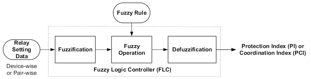
This paper proposes the method of assessing and utilizing the protection level of the overcurrent relay of the power distribution system in a nuclear power plant. For the overcurrent relay protection level assessment is realized in the digital protective relays with the fuzzy logic controller [
1].
Section 2 introduces the results of literature reviews.
Section 3 and
Section 4 introduce a PCI evaluation method.
Section 5 is dedicated to the verification of the methodology introduced in
Section 3 and
Section 4.
Section 6 describes the results of research and discussions. Finally,
Section 7 describes the effectiveness of the PCI evaluation method proposed in this paper as the conclusion of this research.
2. Literature Review for Fuzzy Logic Controller Based Overcurrent Protection
In general, electric motors are protected by a motor protection relay (MPR). If the MPR detect failures or faults in the system, it trips the motor after the preset delay time. If it immediately stops a motor as soon as the system detects an error, then the production line is disrupted. On the contrary, waiting too long without stopping the motor, even when the system is critically faulty, can cause serious faults. In this regard, the results of a recently published study to improve the function and performance of overcurrent relays using the Fuzzy logic controller are described below.
References [
2,
3] suggest using fuzzy logic to put a delay between 0 and 4.5 s depending on the error type. If the fault is not recovered after this waiting time, stopping of the motor should be considered. In reference [
4], a fuzzy logic-based condition monitoring system to detect the condition of an induction motor was proposed. The overvoltage, overcurrent, temperature, voltage unbalance, current unbalance and undervoltage conditions of the induction motor were modeled using the Simulink program. Stress factor of ac induction motor was introduced as a factor for the status of the motor, which can be used by less experienced engineers and for multiple customer processes. Reference [
5] used fuzzy tool box in MATLAB to create a fuzzy inference system for detecting motor failure, and observe the data set to construct fuzzy rules and membership functions. As more insight is required into the data regarding stator current measurements, a membership functions were created with the currents in each phase (negative large zero, positive large). The output variables generated for the motor state are normal, average, and abnormal. A membership function is created by observing the data set and the behavior of the stator currents that are likely to cause the motor to faults.
Reference [
6] proposed a fuzzy logic-based overcurrent protection system for low voltage induction motor protection. Current sensors, timers, current limiters and contactors are used in this system. A current sensor is used to detect overcurrent and provide a signal to the timer. If the current is not too high or at a level that allows continuous operation, the microcontroller signals the current limiter to limit the current. The contactor functions to disconnect the circuit from the mains when the current is high enough to damage the circuit. Reference [
7] proposed a method of applying fuzzy logic to automate the pickup current (
Ip) setting of the inverse overcurrent relay. The fuzzy system uses the measured current to determine the optimal pick-up current value. The algorithm of the fuzzy system estimates the output (
Ip) using two input variables: the pre-fault current (
Ipre) and the current variation (Δ
I).
Ip, which was initially a static value, becomes a dynamic variable and is updated periodically. The second harmonic restraint stabilization method used in the existing transformer differential protection relay may cause malfunctions under internal faults and misoperation during transformer energization. Therefore, recently, new technologies to improve security and reliability have been reported mainly based on fuzzy logic [
8].
As discussed above, in terms of the implementation of artificial intelligence technology, most studies on overcurrent protection focused on fault determination algorithms by fuzzy logic. On the other hand, this paper deals with the evaluation of the protection level of overcurrent relays. The protection level means the level of setting an overcurrent relay compared to the optimum setting to protect the protected equipment to operate within its maximum capacity range and not operate beyond its operational range.
3. Fuzzification of Overcurrent Relay Setting Rule
The scope of this study is the medium voltage network of a nuclear power plant. The medium voltage switchgears are divided into 13.8 kV and 4.16 kV switchgears. The medium voltage switchgears are composed of redundant incoming feeders, motor feeders and transformer feeders. This first defines the overcurrent relay setting criteria with linguistic data and then perform fuzzification of the setting rules.
3.1. Overcurrent Relay Setting Criteria Ubsection
The overcurrent relay consists of an overcurrent element and a high dropout instantaneous element.
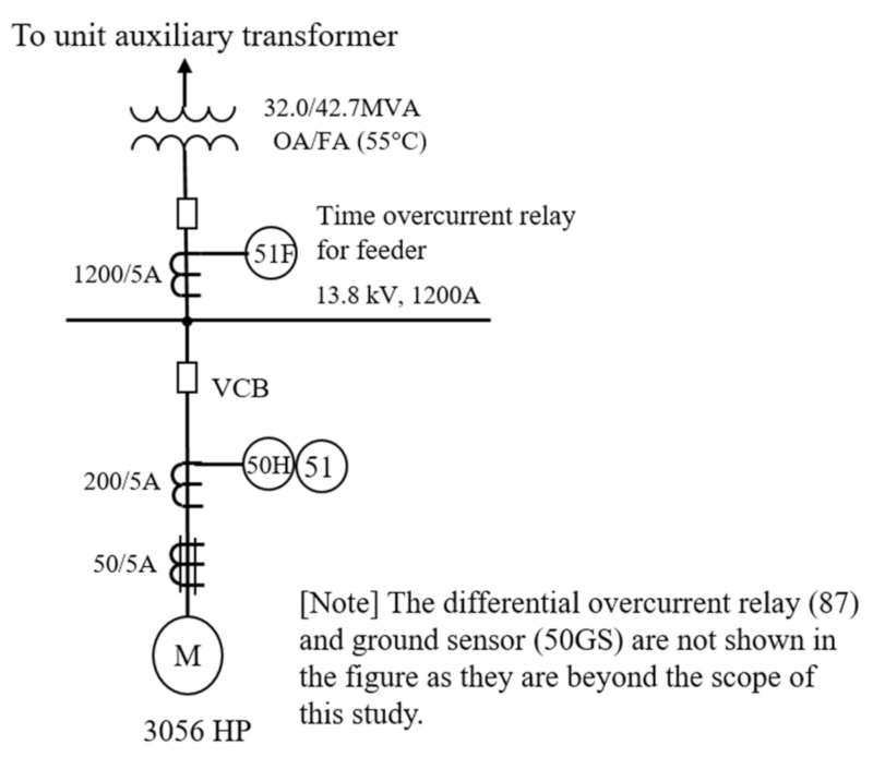
Figure 1 shows the relaying diagram of the condensate pump motor for the Korean standard nuclear power plant. The condensate pump motor protection system was used for the case study of the relay protection index assessment.
Table 1 and
Table 2 show the ratings and setting data of the condensate pump motor.
Time overcurrent relay (TOC; 51) is set at 115% of the full load current (FLC) for smaller than 1500 Hp motors of 4.16 kV switchgear and smaller than 5000 Hp motors of 13.8 kV switchgear, and, it is set at 120~140% of FLC for equal or greater than 1500 Hp motors of 4.16 kV switchgear and equal or greater than 5000 Hp motors of 13.8 kV switchgear [
9]. TOC is used for the alarm only.
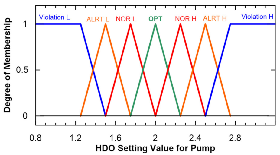
High dropout (HDO; 50H) element is set at 200% of the full load current (FLC) for smaller than 1500 Hp motors of 4.16 kV switchgear and smaller than 5000 Hp motors of 13.8 kV switchgear, and, it is set at 125% of locked rotor current (LRC) for equal or greater than 1500 Hp motors of 4.16 kV switchgear and equal or greater than 5000 Hp motors of 13.8 kV switchgear. HDO permits tripping when the TOC contacts are closed and the current is above the set value. Instantaneous trip (IT) element is set at the next calibration mark above 200% LRC and trip on short circuit only [
9]. In the above example circuit, a differential current relay is used instead of an IT element.
Transformer protection has primary side and secondary side protection. The secondary should be set to approximately 125–200% of its oil-immersed self-cooled (OA) rating and not exceed ANSI points and thermal limit points. And the secondary protection relay setting value should be decided in consideration of protection coordination with downstream relays, inrush current and acceleration time, and constant load current. The setting current of the transformer primary protective relay is set to 200–300% of the transformer OA rating. The instantaneous overcurrent (IOC, 50) relay on the primary side of the transformer is set at the next calibration mark above 175% of the let through fault current [
10].
3.2. Fuzzy Membership Functions of Overcurrent Relays
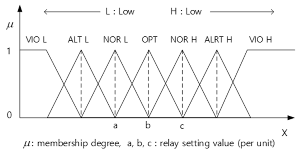
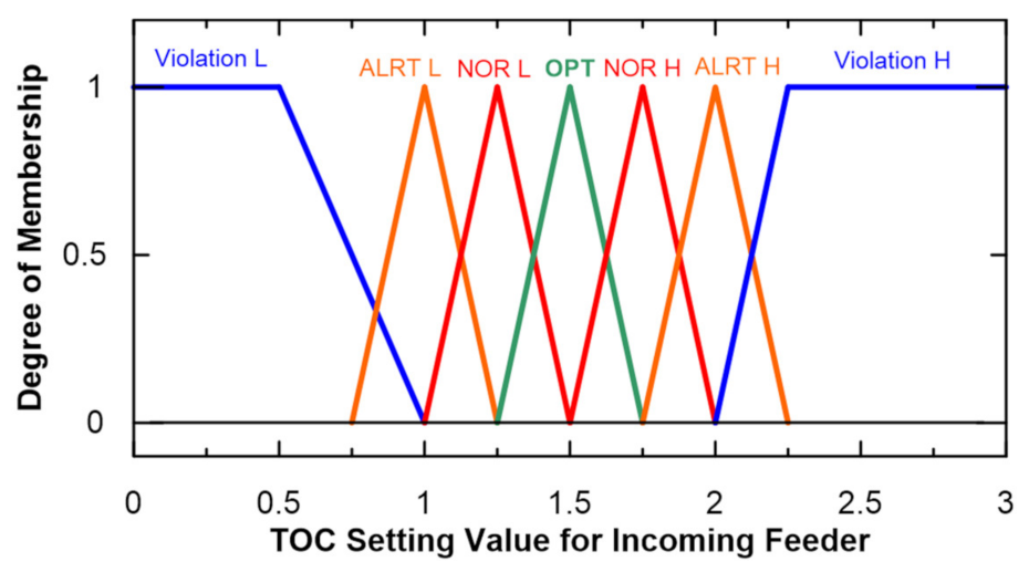
The overcurrent relay protection index is classified into seven fuzzy sets. Optimal (OPT) denotes that the overcurrent relay is set optimally according to the relay setting criteria. OPT is a single set. Normal (NOR) denotes that the overcurrent relay is set within the acceptable range according to the relay setting criteria. Alert (ALT) denotes that the over-current relay is set at a level just before it deviates from the relay setting criteria. Violation (VIO) denotes that the overcurrent relay is set to deviate from the relay setting criteria. Normal (NOR), alert (ALRT), and violation (VIO) sets are divided into a low set and high set as shown in
Figure 2.
According to the setting criteria in
Section 3.1, fuzzy membership functions of overcurrent relays were defined as
Figure 2,
Figure 3,
Figure 4 and
Figure 5. The value of the abscissa in
Figure 3,
Figure 4 and
Figure 5 were defined according to the setting criteria in
Section 3.1. In
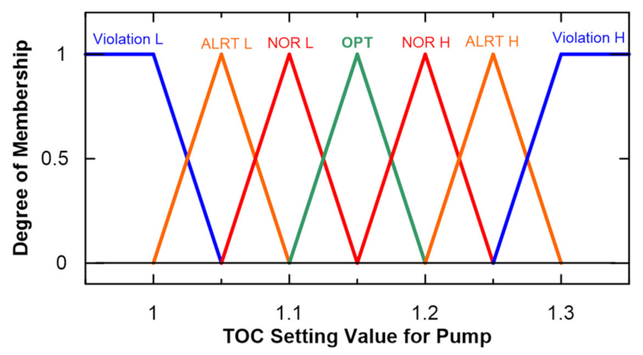
Figure 3, the optimal setting level of time overcurrent relay (TOC; 51) is 115% of the full load current (FLC). It is 1.15 pu of FLC. Then normal low level is 1.1 pu and normal high level is 1.2 pu. If setting level is lower than 1 pu or higher than 3 pu then it is a violation of the setting criteria. The value of the abscissa in
Figure 3,
Figure 4 and
Figure 5 were defined in the same manner as
Figure 2.
3.3. Membership Degree
The degree of membership, μ(x) in each of the fuzzy sets (violation, alert, normal, and optimum) was calculated with fuzzy membership functions and relay setting data.
Membership degree of the fuzzy sets, optimal (OPT), normal (NOR) and alert (ALRT) are calculated using Equation (1) [
11]:
Membership degree of the fuzzy sets, low violation (VIO_L), and high violation (VIO_H) are calculated with Equations (2) and (3).
Accordingly, when the overcurrent relay (51) is set at 1.18 pu of the motor FLC, membership degrees of the time overcurrent relay (51) for condensate pump motor are as follows:
When the high dropout relay (50H) is set at 2.02 pu of the motor FLC, membership degree of the high dropout relay (50H) are as follows:
In the same manner, if the 13.8 kV switchgear incoming feeder protection relay (51) is set at 150% of full load current, the degree of membership are as follows:
Therefore , (1.5) and (1.5) are all zero (0).
4. Fuzzy Operation
4.1. Fuzzy Operation Rules for Device-Wise Protection
Fuzzy rules were defined as follows for the evaluation of device-wise fuzzy memberships. There are a total of 49 rules and the fuzzy associative memory matrix (FAMM) is as shown in
Table 3. The condensate pump motor feeder is provided with HDO and TOC as two protective elements. The device-wise protection of the motor feeder is achieved by a combination of the HDO and TOC relays. HDO and TOC relays have seven fuzzy sets each. So there are 49 combinations and 49 fuzzy rules.
The first 10 rules among them are as follows:
Rule 1 if (TOC is optimal) and (HDO is optimal) then (Fuzzy output is optimal);
Rule 2 if (TOC is optimal) and (HDO is normal_L) then (Fuzzy output is normal);
Rule 3 if (TOC is optimal) and (HDO is normal_H) then (Fuzzy output is normal);
Rule 4 if (TOC is optimal) and (HDO is alert_L) then (Fuzzy output is alert);
Rule 5 if (TOC is optimal) and (HDO is alert_H) then (Fuzzy output is alert);
Rule 6 if (TOC is optimal) and (HDO is violation_L) then (Fuzzy output is violation);
Rule 7 if (TOC is optimal) and (HDO is violation_H) then (Fuzzy output is violation);
Rule 8 if (TOC is normal_L) and (HDO is optimal) then (Fuzzy output is normal);
Rule 9 if (TOC is normal_L) and (HDO is normal_L) then (Fuzzy output is normal);
Rule 10 if (TOC is normal_L) and (HDO is normal_H) then (Fuzzy output is normal).
The above fuzzy operation result can be summarized as
Table 3: Fuzzy rule table for the medium voltage motor protection.
In the process of defuzzification, fuzzy membership sets should be converted to crisp quantity. Therefore, weighting factors in
Table 4 were provided for the fuzzy membership sets in
Table 3, where weighting factors are defined as; optimal is 1, normal is 0.66, alert is 0.33 and violation is 0.0. This means that the optimal setting condition of the relay is considered as unit (1) and the violation is considered as zero (0) condition.
4.2. Fuzzy Operation Rules for Pair-Wise Protection Coordination
Pair-wise protection coordination means the protection coordination between the downstream motor protection and the upstream switchgear incoming feeder protection as shown
Figure 1. There are a total of 28 rules and FAMM is shown in
Table 5. As shown in
Table 5, the branch feeder have four (4) device-wise fuzzy sets and the incoming feeder have seven (7) device-wise fuzzy sets. The incoming feeder has only one protective element. The combinations of pair-wise fuzzy sets between the branch feeder and incoming feeder are 28, as shown in
Table 6.
The first 10 rules of them are as follows:
Rule 1 if (TOC_feeder is optimal) and (Device-wise is optimal) then (Pair-wise is optimal);
Rule 2 if (TOC_feeder is normal_L) and (Device-wise is optimal) then (Pair-wise is normal);
Rule 3 if (TOC_feeder is normal_H) and (Device-wise is optimal) then (Pair-wise is normal);
Rule 4 if (TOC_feeder is alert_L) and (Device-wise is optimal) then (Pair-wise is alert);
Rule 5 if (TOC_feeder is alert_H) and (Device-wise is optimal) then (Pair-wise is alert);
Rule 6 if (TOC_feeder is violation_L) and (Device-wise is optimal) then (Pair-wise is violation);
Rule 7 if (TOC_feeder is violation_H) and (Device-wise is optimal) then (Pair-wise is violation);
Rule 8 if (TOC_feeder is optimal) and (Device-wise is normal) then (Pair-wise is normal);
Rule 9 if (TOC_feeder is normal_L) and (Device-wise is normal) then (Pair-wise is normal);
Rule 10 if (TOC_feeder is normal_H) and (Device-wise is normal) then (Pair-wise is normal).
The weighting factors in
Table 6 are applied to the fuzzy outputs in the process of defuzzification.
4.3. Device-Wise Fuzzy Logic Operation and Defuzzification
Form the calculation result of
Section 3.2, the membership degree of each relay element are as follows:
To find the device-wise fuzzy membership degree fuzzy intersection operation was performed.
Then,
where
μoo is membership degree of optimal and optimal,
μno is membership degree of normal and optimal,
μon is membership degree of optimal and normal, and
μnn is membership degree of normal and normal pair.
By the defuzzification of the fuzzy outputs convert the fuzzy quantities into crisp quantities. The center of mass defuzzification method of Equation (4) was used:
where
P is defuzzified crisp quantity,
μx is membership degree for point x,
x is weight of membership set.
Based on the center of mass defuzzification method (Equation (4)) device-wise protection index (
Pd) is calculated as below:
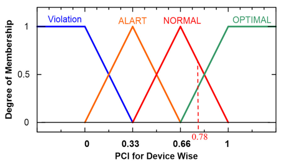
The protection index 0.78 indicates that the motor protection relay setting level is 0.78 pu compared to the Optimal (51)–Optimal (50H) condition of 1 pu. (See
Figure 6) This is also a slightly better condition than the Normal (51)–Normal (50H) protection index of 0.66.
Again, the Pd was converted into a membership degree of each protection condition.
Then, the membership degree of device-wise protection relay is:
4.4. Pair-Wise Fuzzy Logic Operation and Defuzzification
According to the above calculation result, the membership degree of device-wise protection relay and switchgear incoming feeder protection relay are as below.
Then, by the fuzzy intersection operation pair-wise fuzzy membership were calculated.
Based on Equation (4) pair-wise protection coordination index (
Pp) was calculated as below:
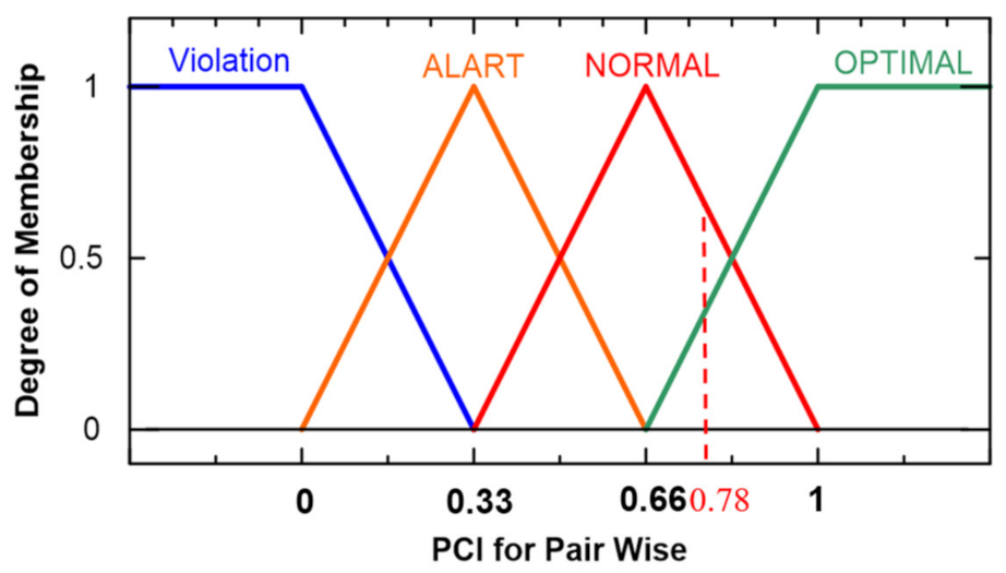
Pair-wise protection coordination index (PCI) is also 0.78. It means that the protection coordination level is in between the normal state and the optimal state as shown in below
Figure 7.
5. Verification by MATLAB Simulation
5.1. Modeling Fuzzy Logic Controller
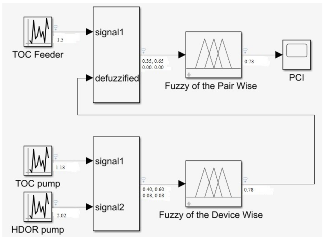
Fuzzy logic controllers were modeled using the MATLAB Simulink program as shown in
Figure 8 [
12].
Device-wise fuzzy logic controller was modelled with the membership functions shown in
Figure 3 and
Figure 4, and the operational rules defined in
Section 4.1. Using the membership functions of the switchgear input feeder’s time overcurrent relay, the output of the device-wise fuzzy controller and the operation rules defined in
Section 4.2, the pair-wise fuzzy logic controller was modeled.
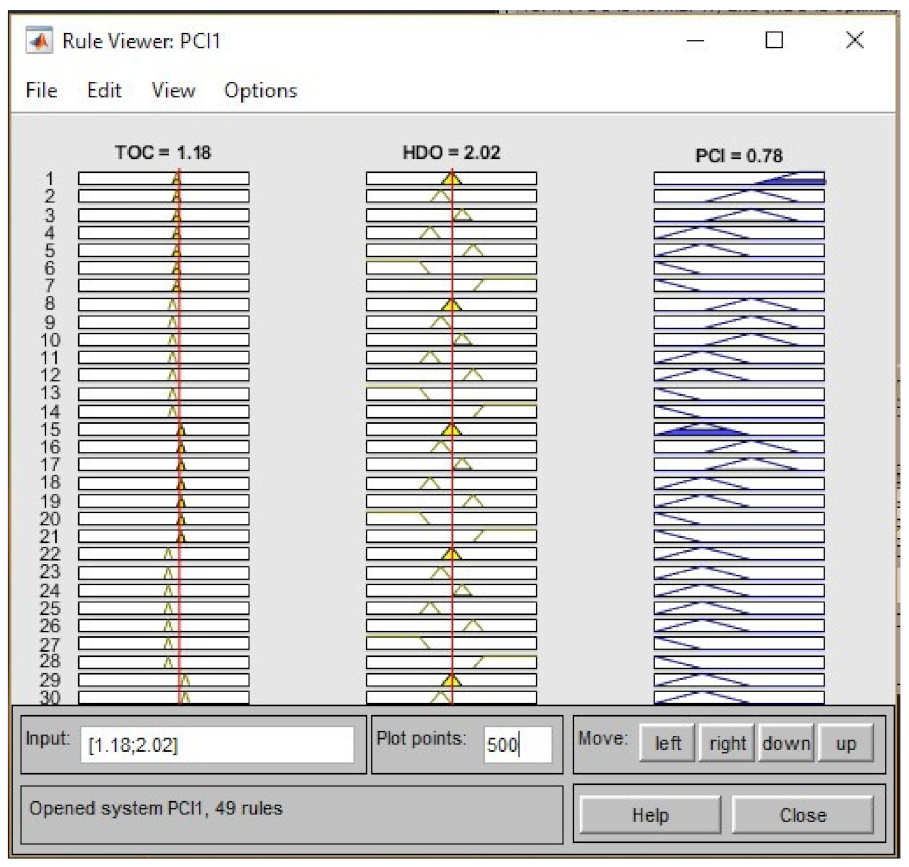
The output of the pair-wise fuzzy logic controller is the pair-wise protection coordination index. After implementing the fuzzy logic controller in MATLAB, it was used to verify the PCI evaluation results of the manual calculation, which was carried out in
Section 3 and
Section 4. It was also used to verify the behavior of the fuzzy logic controller under the same relay setting levels and different system operation conditions. When the setting levels of the TOC and HDO relays for the pump are set at 1.18 pu and 2.02 pu of FLC, respectively, the output (device-wise PCI) was 0.78, as shown in
Figure 9.
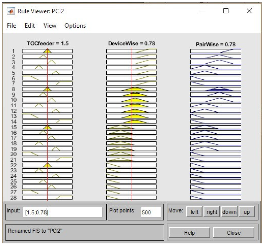
It is the same as the result of the hand calculation. The second fuzzy logic controller that is for the TOC of the incoming feeder was set to 1.5 pu, and, the output of the first fuzzy logic controller is 0.78. As a result the pair wise protection coordination index is 0.78 as shown in
Figure 10. The pair wise protection coordination index is also the same as the result of the manual calculation.
5.2. Case Study for Different System Operation Condition
Depending on the transformer operating conditions, the cooling mode and temperature rise limit may change. In other words, the allowable capacity of the transformer depends on the operating conditions. So when the cooling mode or temperature rise limit changes, the FLC of the transformer changes. In the study case, the time overcurrent relay installed in the transformer secondary side was set at 1912.5 A. As specified in
Section 3.1, the recommended setting level of the time overcurrent relay is 1.25 to 2.0 pu of the full load current at OA mode.
Table 7 shows the pu of the relay setting current based on the FLC at each operation condition.
When the transformer is operating at OA mode and the temperature rise condition is 55 °C, the relay setting level is 1.5 pu of the FLC. This means, according to
Figure 5, the relay protection index is ‘Optimal (1.5)’.
6. Results and Discussion
The current electrical protection system is operated regardless of the operation conditions of the electrical system after setting the relay once. In some cases, this may result in the relay set value falling outside the appropriate level [
13]. This paper proposed a method to evaluate device-wise protection index (PI) and pair-wise protection coordination index (PCI) using a fuzzy logic controller. The PI indicates how accurately the overcurrent relay has been set and the PCI indicates how optimally relays have been coordinated according to the relay setup guidelines. In other words, this research proposed a method for the operator to check the protection level of the overcurrent relays as needed. Overcurrent relays require protection cooperation between downstream and upstream relays. The downstream relay for the protection of the condensate pump motor, is a combination of high dropout overcurrent relay (50H) component and time overcurrent relay (51) component. Device-wise PI was obtained using the component level’s fuzzy membership degrees and fuzzy rules. The device-wise protection index (PI) of the motor overcurrent relay in
Figure 1 is 0.78. According to
Figure 7, 0.78 is the higher value than Normal (0.66) and lower value than Optimal (1). It is not the optimum level, however, it is pretty good level and obtains PCI for each pair by performing fuzzy operations once again with PI for each device and PI for upstream relay.
Figure 11 shows the fuzzy inference process used in this study.
By the above method, it is possible to evaluate the PCI variation in the overcurrent relay when the operation mode of the auxiliary transformer of the power plant is changed. According to the result, it may be possible to provide an alarm for the operator when the relay protection index is alert level. It is also possible to adjust the overcurrent relay’s setting level using protection coordination index if required due to the change of system configuration or equipment capacity. In
Section 5, the calculation processes of
Section 3 and
Section 4 were verified using MATLAB. The verification results were consistent.
The main purpose of this paper is to propose a PCI evaluation algorithm. In this paper, the basic principles are presented. In practical systems, the system configuration of the power distribution system is larger and more complex than
Figure 1. However any power distribution switchgear or distribution panel can also be decomposed into device-wise and pair-wise components. Thus, protection zone is divided into two categories; device-wise and pair-wise. The pair-wise protection means coordination between upstream relay and downstream relay.
7. Conclusions
Currently, there is no way to know how well the overcurrent relay is set. This paper proposed a PCI evaluation method for overcurrent relays using the fuzzy logic controller, which converts linguistic language to crisp language. This is a completely new and unique idea. PCI provides electrical system operators with the appropriateness of overcurrent relay setting levels and adjustment results. Therefore, PCI helps electrical engineers operate distribution systems safely and reliably.
As the unit capacity of the plant grows, the capacity of the electric power system continues to increase, as well as the complexity of the electric power system. In particular, the introduction of distributed power will further increase the complexity of the power system. Therefore, it is sometimes necessary to adjust the set value of the over-current system according to the various operation modes. Due to the advancement of digital protection relay, the setting of the protective relay can be implemented remotely.
The assessment of PCI discussed and proposed in this paper is the core part required to make the autonomous protection and coordination system for overcurrent protection relays. If the algorithm introduced in this paper is included in the digital relay, autonomous relay setting and adjustment will also be made. Following this study, research will be conducted on how to implement a reliable high-speed autonomous relay setting and adjustment system for the auxiliary power systems of power generating stations.


