Article

Research on Module Layout and Module Coverage of an Automobile Exhaust Thermoelectric Power Generation System

1
Automotive Engineering Research Institute, Jiangsu University, Zhenjiang 212013, China
2
School of Automotive and Traffic Engineering, Jiangsu University, Zhenjiang 212013, China
*
Authors to whom correspondence should be addressed.
Energies 2022, 15(3), 987; https://doi.org/10.3390/en15030987
Submission received: 9 December 2021 / Revised: 20 January 2022 / Accepted: 21 January 2022 / Published: 28 January 2022
(This article belongs to the Topic Thermoelectric Energy Harvesting)

Abstract

:
Due to the low efficiency of thermoelectric generators (TEGs), many scholars have focused on the structural optimization of TEGs rather than on the optimization of the layout of thermoelectric modules. We aimed to investigate the effect of module layout on the output power of an automotive exhaust thermoelectric power generation system. The module spacing and module coverage ratio were compared under different working conditions based on a numerical simulation. The results show that, under high-temperature conditions, when the module spacing expands from 5 mm to 35 mm, the output power growth rate of modules of different sizes ranges between 8% and 9%. Moreover, under low-temperature conditions, a high coverage ratio of modules will not increase the total output power but, instead, make it decline. In fact, choosing a larger-size module can improve the temperature uniformity, thereby increasing the output power of the automotive thermoelectric power generation system. Hence, the present study has verified that, under different working conditions, different module layouts and module coverage ratios have an impact on the output power of the thermoelectric power generation system, which sheds new light on the improvement of automotive thermoelectric power generation systems.

1. Introduction

While automobiles bring comfort and convenience to human beings, they also cause problems such as energy shortages and environmental pollution. About 40% of the energy produced by the combustion of automobile fuel is dissipated in the form of exhaust heat [1,2]. Therefore, the reasonable recovery of waste heat from automobile exhausts can effectively improve fuel reusability and allow energy-saving measures and emission reduction [3]. In recent years, thermoelectric power generation technology has attracted wide attention from scholars at home and abroad due to it having the advantages of small size, light weight, no noise, and no pollution [4,5,6]. However, it has not been widely used in the automotive industry due to its low efficiency, the high cost of thermoelectric modules (TEM), the non-uniform temperature distribution of the hot side, space limitations, and parasitic penalties [7,8]. Therefore, many experts and scholars have tried to improve the efficiency of thermoelectric recovery by looking for better thermoelectric materials or optimizing the structural design of thermoelectric generators [9].
For the optimal design of thermoelectric modules, many researchers have mainly focused on the length, shape, and number of thermoelectric legs, as well as the cross-sectional area. Min et al. [10] found that when the length of the thermoelectric leg was reduced by 55%, the output power increased by 48%, while the conversion efficiency was reduced by less than 10%. Kumar et al. [11] used numerical methods to study the thermoelectric modules of Skutterudite, and the results showed that a certain leg height and filling rate can increase the maximum output power and reduce the amount of material used. Similarly, Shen et al. [12] studied the performance of segmented thermoelectric coolers and found that the maximum cooling capacity, the maximum temperature difference, and the maximum performance coefficient all decreased with an increase in leg length. Nemati et al. [13] investigated an electrically separated two-stage thermoelectric cooler and concluded that the best cross-sectional area ratio was less than 1. Shittu et al. [14] used a three-dimensional model to study the optimal geometric structure of a hybrid photovoltaic–thermoelectric (PV–TE) unicouple that could achieve the maximum efficiency and discovered that the efficiency of the hybrid PV–TE unicouple increased with the increase in the cross-sectional area of the leg. Lamba et al. [15] examined the influence of the thermoelectric leg configuration on the performance of the thermoelectric power generation system and revealed that the exergy and energy efficiency of the trapezoidal thermoelectric generator (TEG) increased by 2.31% and 2.32%, respectively, under a certain thermoelectric leg configuration. Fabián-Mijangos et al. [16] conducted numerical and experimental studies on thermoelectric generators with asymmetrical thermoelectric legs and proved the impact of the performance of thermoelectric power generation on the improvement. In a similar vein, Karana et al. [17] also verified that an asymmetrical design could increase the output power. Hodes et al. [18] proposed a method by which to optimize the number of thermoelectric legs to obtain the maximum output power or conversion efficiency. Their results showed that in the cooling mode, the number of thermoelectric legs had no effect on performance or efficiency, whereas in the power generation mode, under a specific power output and load resistance, the number and height of thermoelectric legs must be optimized at the same time. Ji et al. [19] used simulations and experiments to study the number of thermoelectric legs on power generation sheets, and the results showed that the output power increased with the increase in the number of thermoelectric legs, but the efficiency declined after an initial increase. Similarly, Luo et al. [20] found that as the number of thermoelectric legs increased, the maximum output power and maximum efficiency of the thermoelectric power generation module increased by 1% and 1.2%, respectively.
The optimized design of the heat exchanger mainly focuses on its shape and internal structure. Exhaust pressure drop is an important parameter for evaluating the rationality of the optimized design, which needs to be elaborated further. The heat exchanger mainly consists of two shapes—namely, a flat plate and a hexagon. The flat-plate heat exchanger has a simple structure, which permits an easy arrangement of a large number of thermoelectric modules on the upper and lower surfaces. Nonetheless, the corresponding temperature distribution between the modules is uneven. A hexagonal heat exchanger guarantees a better uniformity of the hot-surface temperature distribution, but the structure is rather complicated, and the modules are hard to install [21]. Thacher et al. [22] designed a rectangular exhaust heat exchanger with offset fins. Experiments have shown that fuel efficiency can be improved by about 1–2% with this method. Crane et al. [23] invented a cylindrical heat exchanger to simplify the structure of the thermoelectric generator and reduce the generator’s volume. Experiments have shown that the maximum fuel efficiency of the BMW X6 equipped with this type of thermoelectric generator is increased by more than 1.2%. Deng et al. [24] compared the flat-plate and hexagonal heat exchangers and found that, under the same inlet conditions, the average temperature of the hot surface of the flat-plate heat exchanger was higher. Kim et al. [21] designed the exhaust pipe into a hexagon and evaluated the performance of the hexagonal thermoelectric generator under eight working conditions. The experimental results showed that the pressure drop was 2.1 KPa when the maximum output power was 98.8 W. Luo et al. [25] proposed a converging thermoelectric power generation system, which led to higher output power and lower back-pressure power loss, compared with the traditional structures. Specifically, when the air temperature was 550 K, and the air mass flow was 60 g/s, the output power of the tapered thermoelectric power generation system was about 5.9% higher than that of the traditional system. A group of scholars also attempted to improve the temperature distribution and increase the surface temperature of the hot side by optimizing the internal structure of the heat exchanger. Bai et al. [26] conducted a numerical study on six heat exchangers with different internal structures and found that the series plate heat exchanger had the highest heat transfer capacity and pressure drop. Vale et al. [27] designed two heat exchangers with plain fins and offset strip fins, the former of which had a better performance. Wang et al. [28,29] proposed a heat exchanger with cylindrical grooves on the surface and studied the influence of channel height on TEG performance. The numerical simulation results showed that, in comparison with fin-type heat exchangers, heat exchangers with cylindrical grooves can improve the efficiency of thermoelectric power generation modules under low back pressure, with 8 mm as the optimal height of the channel. Marvão et al. [30] studied three heat exchangers with plain fins, offset strip fins, and triangular fins and discovered that thinner fins can better increase the net power. Pacheco et al. [31] artificially enhanced heat transfer by embedding a heat pipe in the channel, which caused a large pressure drop due to the small channel size. Fernández-Yañez et al. [32] studied four internal structures of heat exchangers, including one type of long fins, two types of short fins, and one type of channel-arranged fins. The long-fin structure performed better when taking heat transfer and pressure drop into consideration.
Other scholars have also conducted research on the arrangement and quantity of thermoelectric power generation modules. Favarel et al. [33,34] studied the module coverage ratio of the modular thermoelectric power generation system through numerical simulations and experiments. Their results showed that there was an optimal coverage ratio for each thermoelectric device, which also confirms the necessity of optimizing the location and number of modules. Li et al. [35] performed a three-step optimization on the number of modules and the distribution model of the hexagonal thermoelectric power generation system. The research results further confirmed the existence of an optimal number and distribution, and exceeding these will lower the output power. Rakesh et al. [36] studied four TEM electrical connection methods (i.e., series–parallel, all-tied, bridge-joint, and bee-hive structures) using MATLAB (Simulink) under uniform and non-uniform temperature distribution conditions. Their results showed that the bridge-joint structure was able to achieve the maximum output power. Samir et al. [37] proposed a model for predicting the electric behavior of vehicle thermoelectric generators at different operating points. The simulations and experiments showed that, under non-uniform thermal surface conditions, the interconnection of thermoelectric modules has a significant negative effect on electricity generation. The pertinent literature mostly concerns power generation modules of the same size, taking the layout and amount of these modules as variables. Thus, these studies have neglected the impact of module size on automobile exhaust thermoelectric power generation systems. This current study took this factor into account, thereby enriching the existing research. Moreover, we also investigated the impact of module spacing and coverage ratio on an automobile exhaust thermoelectric power generation system in great detail.
In summary, much of the literature centers on the structural optimization of thermoelectric generators rather than on the optimization of the layout of thermoelectric power generation modules. Moreover, previous studies have not considered the influence of module spacing on the thermoelectric power generation system. Therefore, we compared the module spacing and module coverage under different working conditions, with the aim of confirming the feasibility of improving the thermoelectric power generation system’s performance through a reasonable module layout optimization. By achieving this objective, the study can provide a reference for the module layout of automobile exhaust thermoelectric power generation systems.

2. Materials and Methods

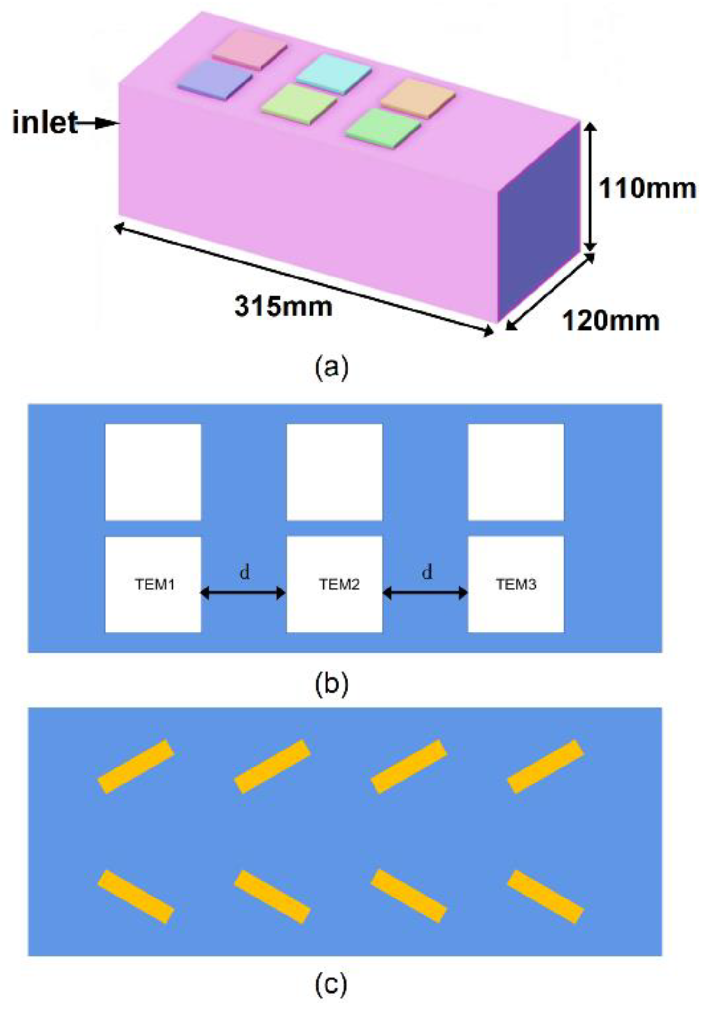
2.1. Thermoelectric Power Generation Model

The thermoelectric power generation system usually consists of an exhaust channel and a thermoelectric power generation module. The thermoelectric module is arranged above the channel. The hot side of the module absorbs heat, and the cold side dissipates heat. Electricity is generated through the Seebeck effect. The flat-plate thermoelectric power generation device can lay the thermoelectric modules on the upper and lower surfaces of the box under the rectangular exhaust channel. It has the advantage of enormous module numbers and is convenient for arranging the cooling water box. Therefore, we used a rectangular exhaust channel box. In the middle of the exhaust channel was a rectangular parallelepiped with a size of 315 mm × 120 mm × 110 mm [38]. The channel contained fin spoilers to enhance the heat transfer effect. The size of the fins was 40 mm × 10 mm × 10 mm. The simulation model is shown in Figure 1, for which three types of square thermoelectric modules were selected with side lengths of 30 mm, 40 mm, and 50 mm, respectively, and a thickness of 3.8 mm. The module spacing and module coverage were studied under three different working conditions. The materials of the three types of modules were identical, but the size of the modules was different, due to the different number of thermoelectric legs made up of bismuth telluride contained inside. The relevant parameters of modules are shown in Table 1 [39]. To control the variables, the number of modules was set at six, the layout of which is shown in Figure 1. Due to the symmetry of the model, the temperatures of the hot side of the modules in the study of module spacing are represented by three modules located on the same side—namely, TEM1, TEM2, and TEM3.

2.2. Model Assumptions and Governing Equations

2.2.1. Model Assumptions

In this study, the following model assumptions were included:
(1)
Automobile exhaust fluid was regarded as a steady-state incompressible ideal fluid;
(2)
The contact thermal resistance between the module and the heat exchanger was ignored;
(3)
The influence of gravity was neglected;
(4)
The influence of heat radiation was not considered.

2.2.2. Governing Equations

Continuity equation:
u x + v y + w z = 0
Momentum conservation equation:
ρ ( u u x + v v y + w w z ) + p x = μ ( 2 u x 2 + 2 u y 2 + 2 u z 2 )
ρ ( u u x + v v y + w w z ) + p y = μ ( 2 v x 2 + 2 v y 2 + 2 v z 2 )
ρ ( u u x + v v y + w w z ) + p z = μ ( 2 w x 2 + 2 w y 2 + 2 w z 2 )
where u , v , and w represent the velocity components in the direction of x , y , and z , respectively. ρ is the fluid density, and μ is the dynamic viscosity.
Taking the high Reynolds’ number for flow in an automobile exhaust pipe into consideration, we used the k ε turbulence model and a simple algorithm to solve the model in ANSYS Workbencn21 software, and the convergence standard of each residual error was set at 10−6.

2.3. Boundary Conditions

In this study, three different working conditions were considered [40]. The relevant parameters are shown in Table 2. The convective heat transfer coefficient of 30 W / ( m 2 · K ) was selected for the outer surface of the heat exchanger, the ambient temperature was 300 K , and the cold side of the module was set to 3000 W / ( m 2 · K ) to replace the heat dissipation effect of the water cooling [41].

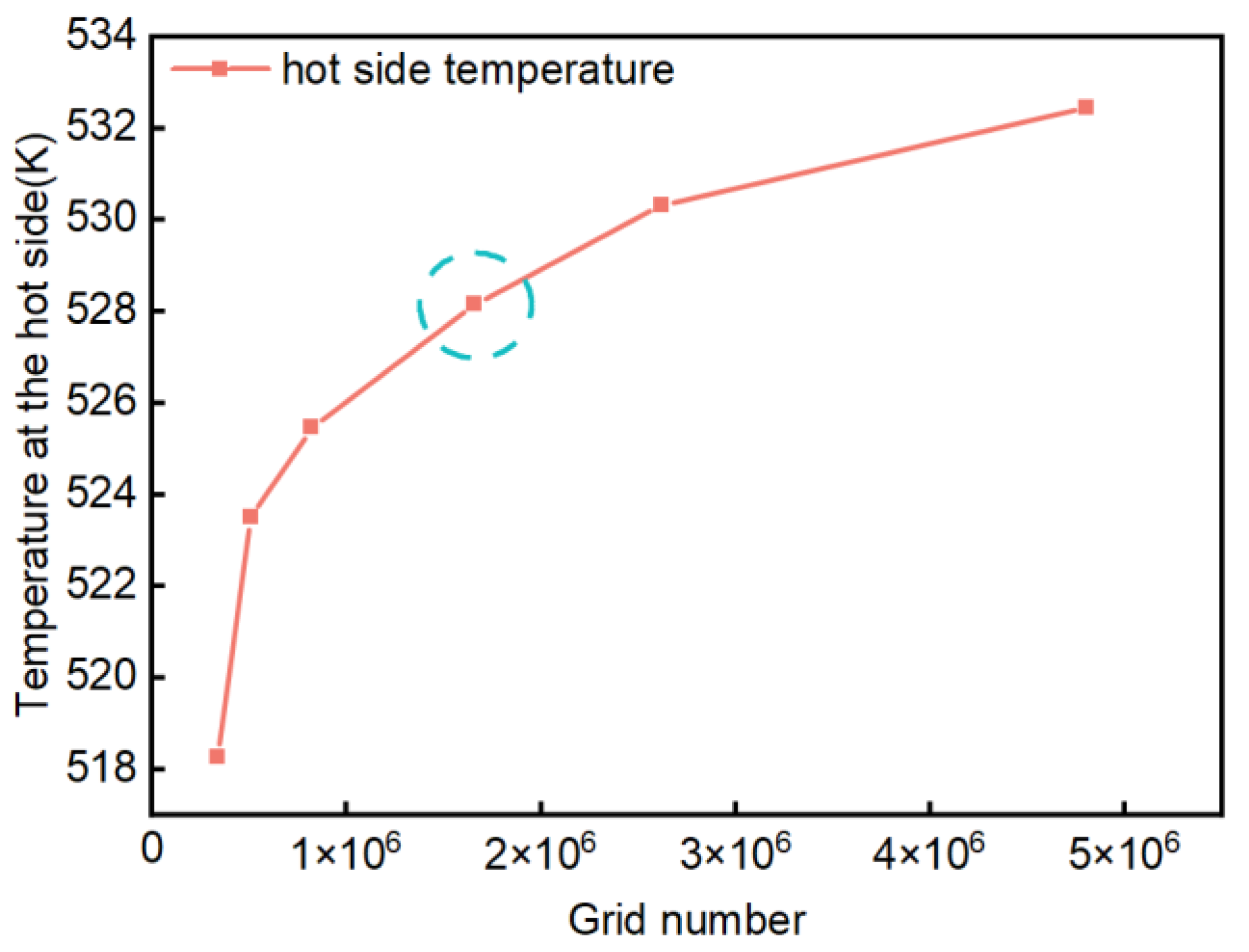
2.4. Grid Independence Verification

In the present study, six different grid numbers were selected. Simulation analyses were carried out for each module under the conditions of an inlet gas velocity of 30 m / s and an inlet gas temperature of 678 K . The relationship between the number of grids and the temperature of the hot side of the module is shown in Figure 2. Taking the simulation accuracy and the time required for the simulation into consideration, the grids were divided based on the method in the circled dotted line. Thus, the number of grids was 1,658,970.

2.5. Power Calculation

Module Power Calculation

When the temperature of the cold and hot sides of a pair of thermoelectric legs (PN segments) is determined, the open-circuit voltage can be calculated through the following formula:
U 0 = ( α P α N ) × ( T h T c )
where α P and α N represent the Seebeck coefficient of P-type and N-type semiconductors, respectively. T h and T c stand for the temperature of the hot side and cold side of the thermoelectric legs, respectively. A single thermoelectric module is composed of multiple thermoelectric legs, and the open-circuit voltage of a single thermoelectric module is as follows:
U M = n U 0
where n is the number of thermoelectric legs in the thermoelectric module.
The formulae for calculating a single module’s current and output power are as follows:
I L = U M R i n + R L = n ( α P α N ) ( T h T c ) R i n + R L
P out = U M 2 R L ( R L + R i n ) 2
where R L is the load resistance, and R i n is the internal resistance of the module. The corresponding calculation formula is as follows:
R i n = n ( ρ N l N A N + ρ P l P A P )
where ρ P and ρ N represent the resistivity of P-type semiconductors, and N-type semiconductors, respectively. l P and l N are the length of PN segments. A P and A N stand for the cross-sectional area of the PN segments.
When the load resistance is equal to the internal resistance, the maximum output power of the module is
P max = n 2 ( α P α N ) 2 ( T h T c ) 4 R i n
The following equation shows the efficiency of the exhaust thermoelectric power generation system:
η = P output m ˙ C p ( T in T out )
where η is the efficiency, Poutput is the thermoelectric generator power output, m ˙ is the exhaust gas mass flow rate, Cp is the exhaust gas specific heat, Tin is the exhaust inlet temperature, and Tout is the exhaust outlet temperature.

3. Results and Discussion

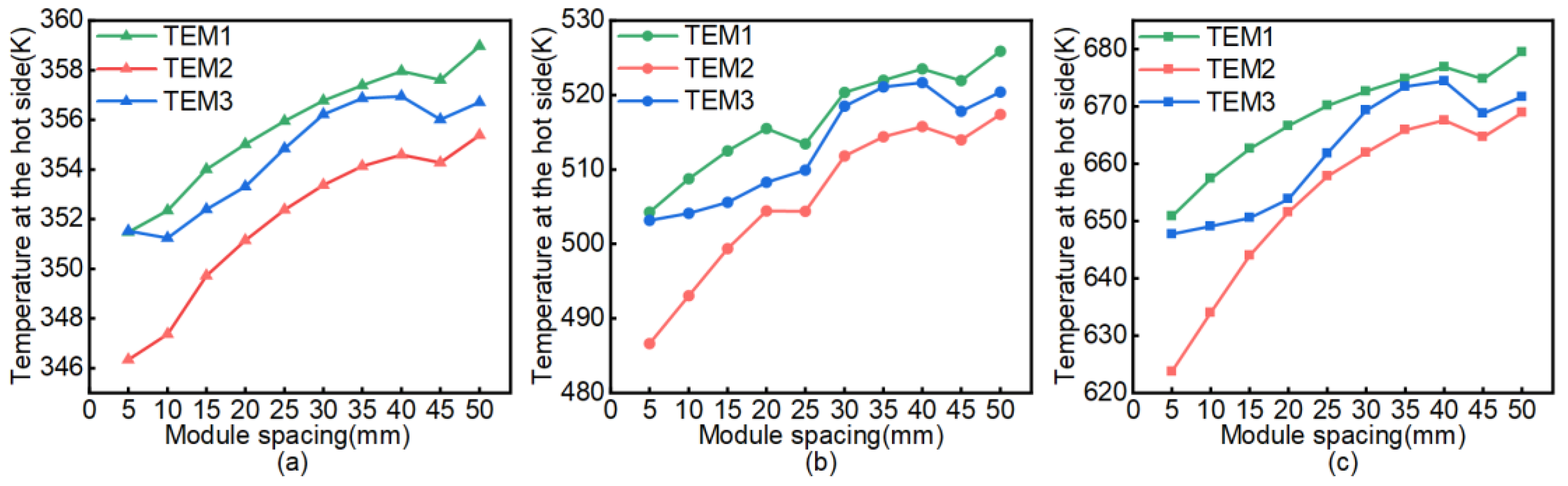
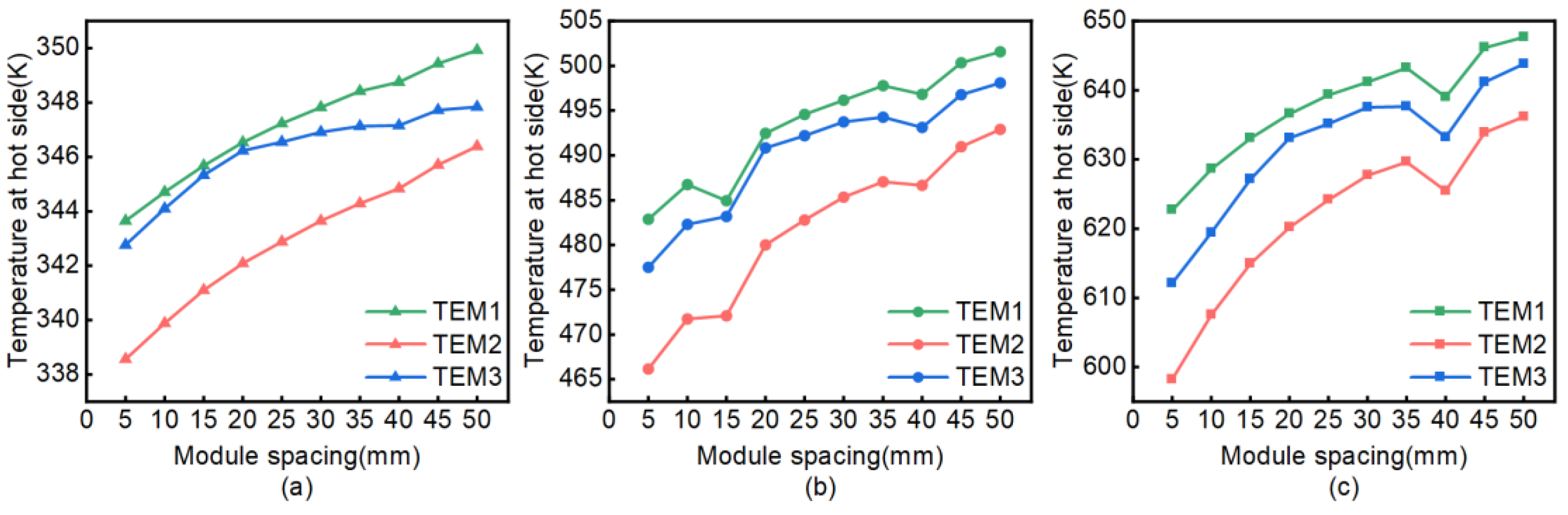
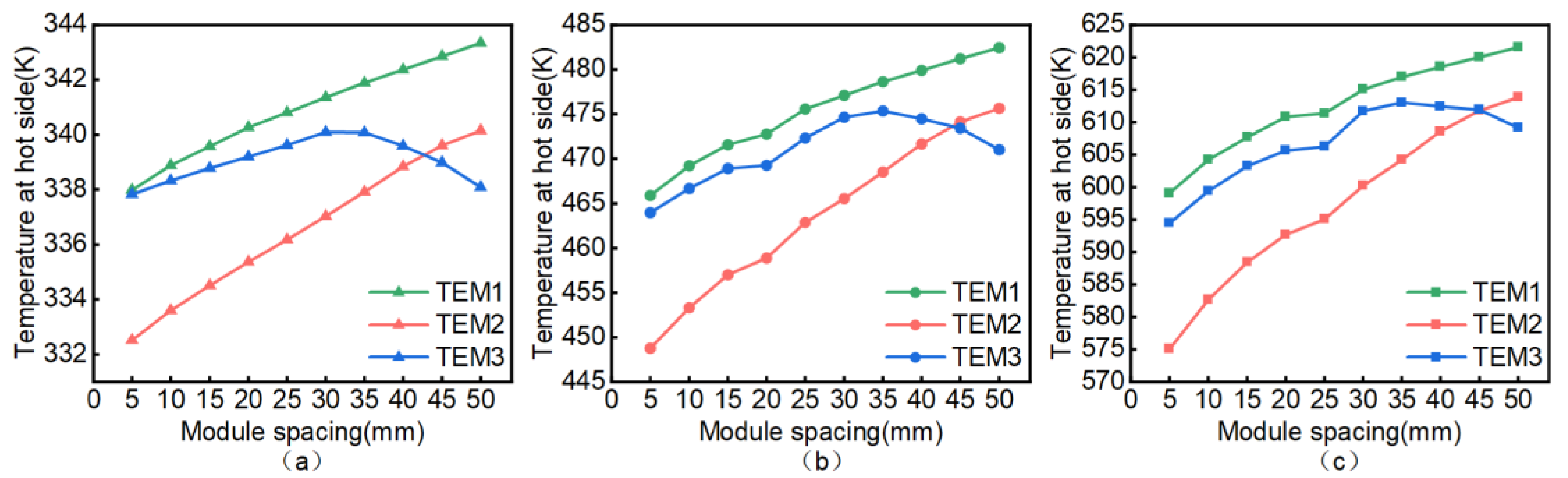
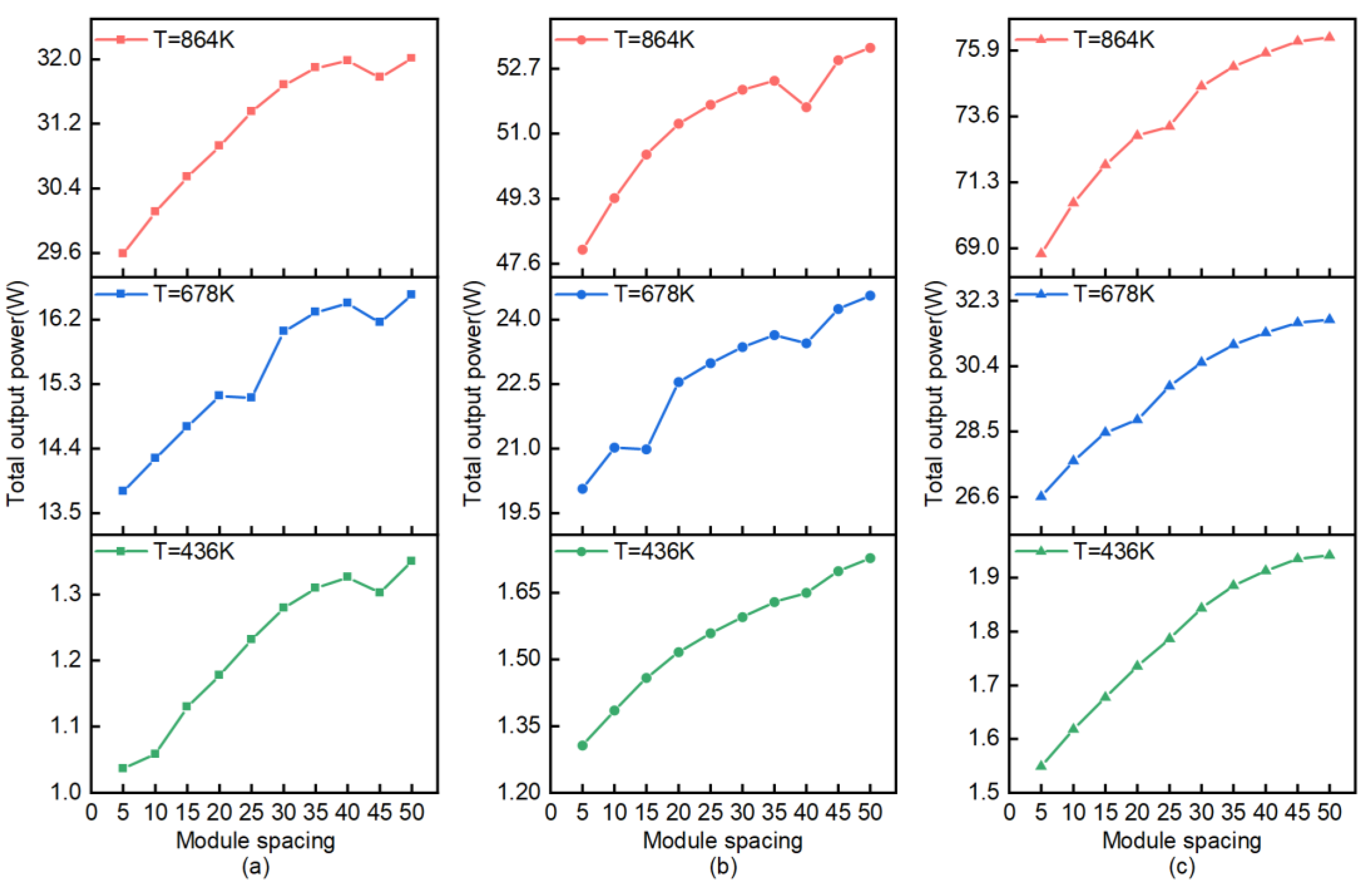
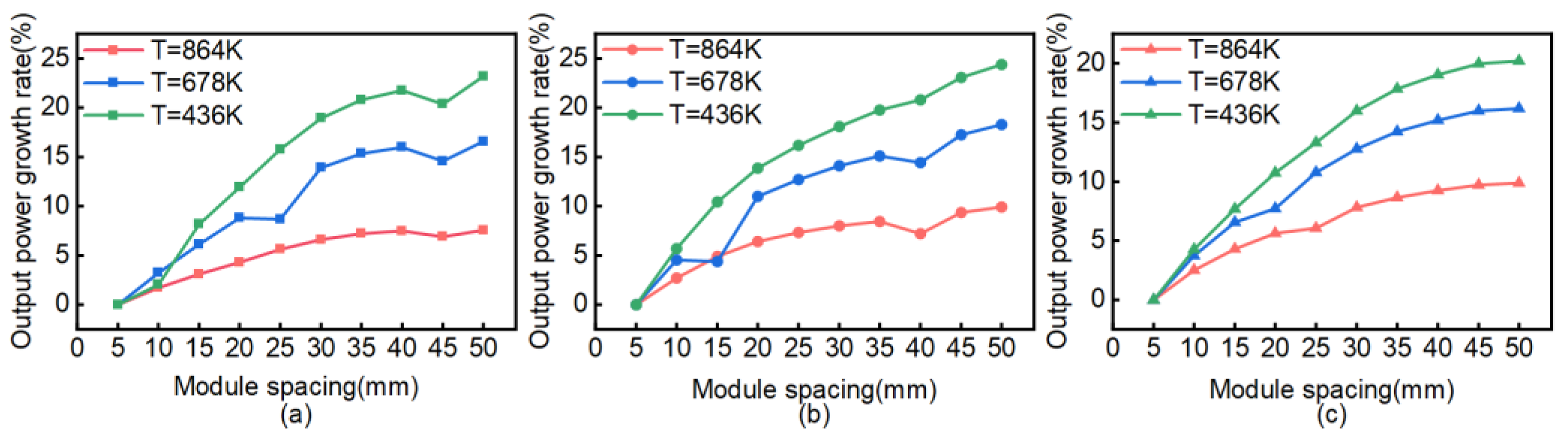
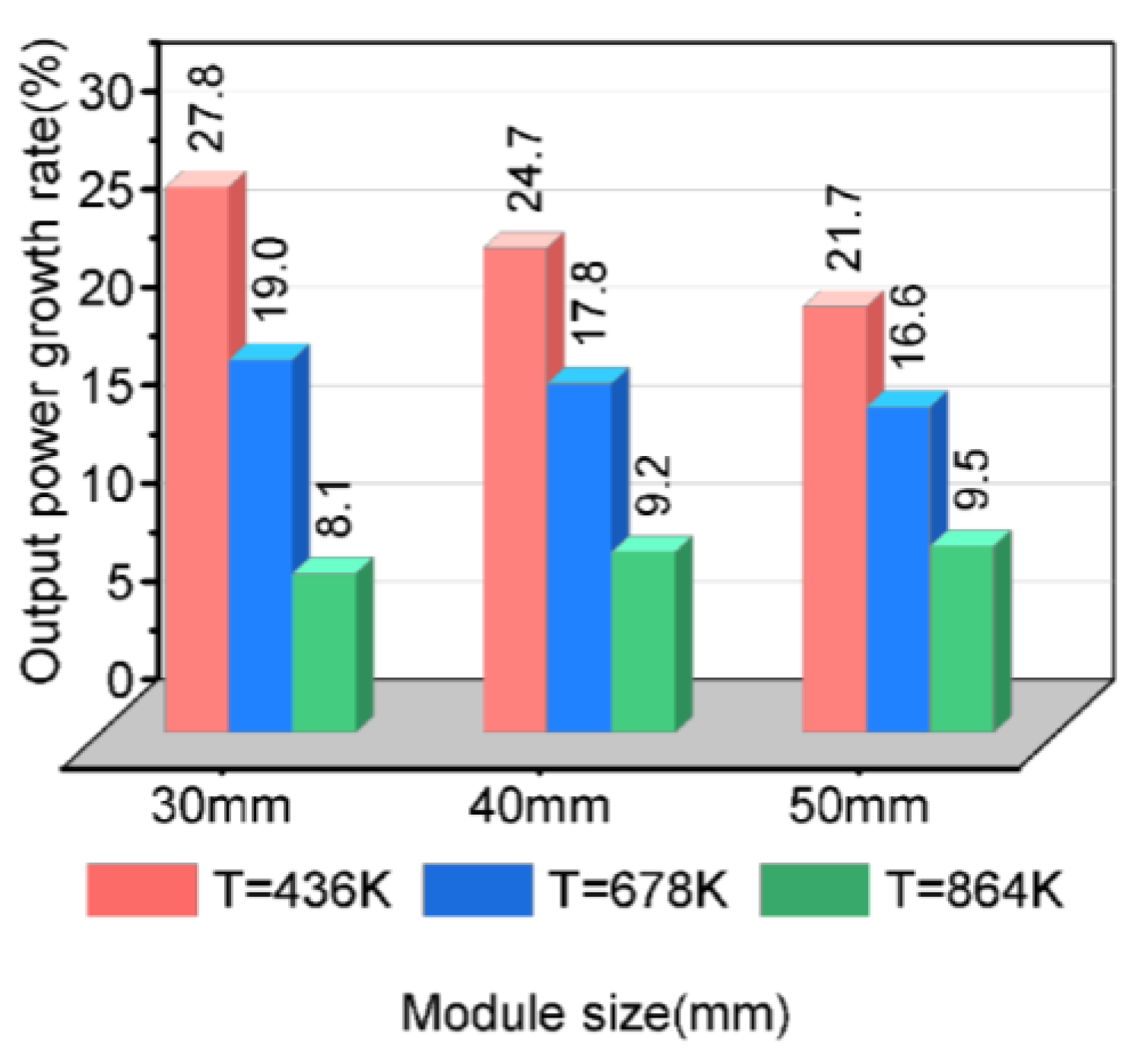
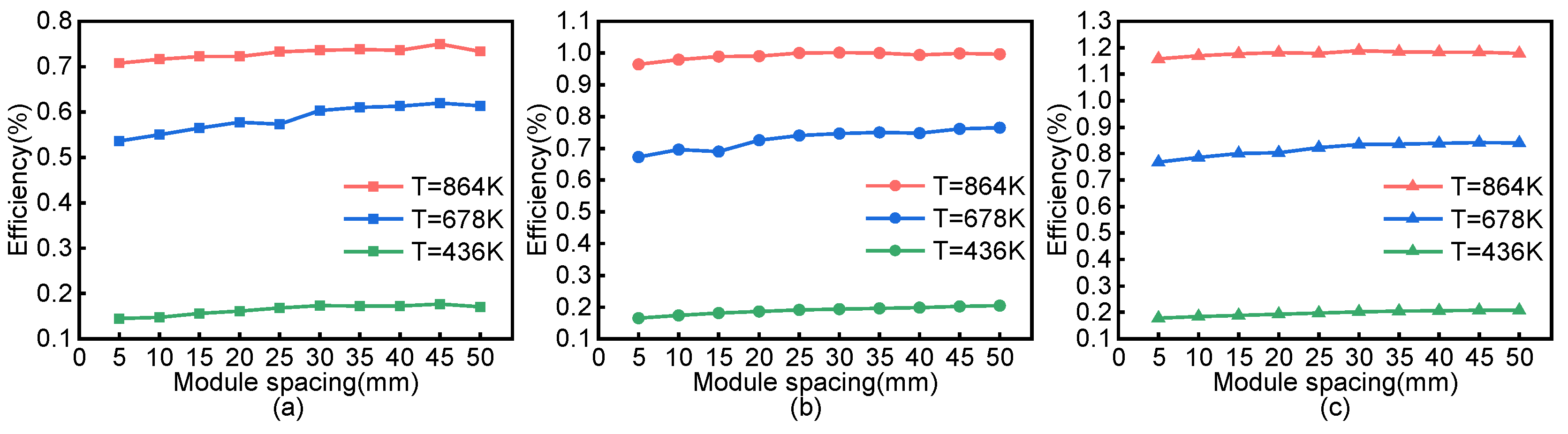
3.1. Research on Module Spacing

We set the total number of modules at six, the size of which differed. The first columns of modules were fixed, and the modules were arranged with spacing ranging from 5 mm to 50 mm in 5 mm intervals. The corresponding simulation calculations were performed under three different working conditions. Due to the symmetry of the model and the relationship between the hot-side temperature and the module spacing, the temperature of the modules’ hot sides is represented by the modules TEM1, TEM2, and TEM3 on the same side.
It can be seen from Figure 3, Figure 4 and Figure 5 that the hot-side temperature of modules was positively correlated with the module spacing. Overall, a larger module spacing led to a higher hot-side temperature. There were also some slight decreases and increases in the hot-side temperature during the process, which was related to the position of the modules and the underlying spoilers. Taking the second working condition of the modules with a side length of 50 mm as an example (Figure 5), Figure 6 displays the hot-side temperature and the spoiler position with a module spacing of 35 mm, 40 mm, and 45 mm. TEM2 in the middle was affected by the front and rear spoilers, and the area of the green temperature area was reduced, which corresponds to a decrease in the module’s hot-side temperature. The position change of the spoiler affected the temperature change of the module. Nonetheless, the module spacing was still the main factor contributing to the module’s temperature change. In different fin arrangements, the density and size of the fins indeed had an impact on the hot-side temperature and power output of the thermoelectric modules. If the fin density and size are small, the exhaust-gas convection heat transfer will be weak, and the hot-end temperature and output power will be low. Nevertheless, if the fin density and size are large, the exhaust-gas convection heat transfer will be strong, and the hot-end temperature and output power will increase, which may also cause a relatively dramatic pressure drop. Therefore, it is necessary to keep the fin density and size within a reasonable range, with the aim of enhancing the convective heat transfer effect of the exhaust gas and increasing the temperature of the hot end of the TEM, thereby increasing the output power of the entire system.
As shown in Figure 4 and Figure 5, TEM2, in the middle of the three modules, had a lower temperature at the hot side but a higher temperature at the two ends. This phenomenon was even more obvious under medium- and high-temperature conditions (Tinlet = 678 K and Tinlet = 864 K). When the module spacing is small, the thermoelectric power generation modules at the front end will absorb part of the heat from the exhaust gas, and the temperature around the thermoelectric power generation modules at the rear end will decrease, resulting in a reduction in the output power of the thermoelectric power generation modules at the rear end. When the module spacing increases, such a mutual influence between modules will be weakened. In the meantime, the back-end modules will absorb more heat, and the output power will increase. Hence, the module thermal temperature rises as the module spacing increases. Hence, when the number of modules is large, a smaller module spacing will have a greater impact on the internal modules, which leads to relatively low hot-side temperature and, thus, affects the output power.
For modules with a side length of 30 mm, when the module spacing was between 30 mm and 40 mm, the hot side performed well under three different working conditions, as shown in Figure 3. In other words, a high hot-side temperature was obtained when the module spacing was relatively small. In a similar vein, for modules with a side length of 40 mm and 50 mm, a module spacing between 30 mm and 40 mm was reasonable.
The temperature difference between the hot and cold sides of modules determines their output power. To put it simply, the rise and fall of the modules’ hot-side temperature impact the magnitude of the output power. Figure 7 demonstrates the relationship between the module spacing and the total system output power. It can be seen that the output power of the module had a similar trend to that of the temperature of the hot side. As the module spacing increased, the output power increased accordingly. Similarly, a higher inlet temperature led to a higher output power of the module. Under the same intake-air temperature condition, larger modules had more internal thermoelectric legs, which led to a higher output power of the modules.
Figure 8 displays the comparative results of the system output power of modules with side lengths of 30 mm, 40 mm, and 50 mm and at a module spacing between 5 mm and 50 mm. When the module spacing was larger than 30 mm, the output power of modules of different sizes witnessed a greater increase under different working conditions. For instance, in Figure 9, when the module spacing was 35 mm, the modules’ output power was not high under low-temperature conditions with a small base value, resulting in a higher growth rate. On the contrary, under high-temperature conditions, the output power growth rate of modules of different sizes was 8~9%. In summary, when the number of modules is set, a reasonable increase in module spacing can increase the output power of the modules.
Efficiency is the ratio of output power to absorbed heat. When the heat is constant, the increase in output power will lead to an increase in efficiency. Figure 10 illustrates that the power generation of modules of different sizes changed little with the increase in module spacing. The power generation efficiency is mainly related to the inlet gas temperature. A higher inlet temperature leads to a higher amount of power generation, thereby increasing the corresponding power generation efficiency. The power generation efficiency of modules of different sizes was about 0.15% under low-temperature conditions, from 0.5% to 0.8% under medium-temperature conditions, and from 0.7% to 1.2% under high-temperature conditions.

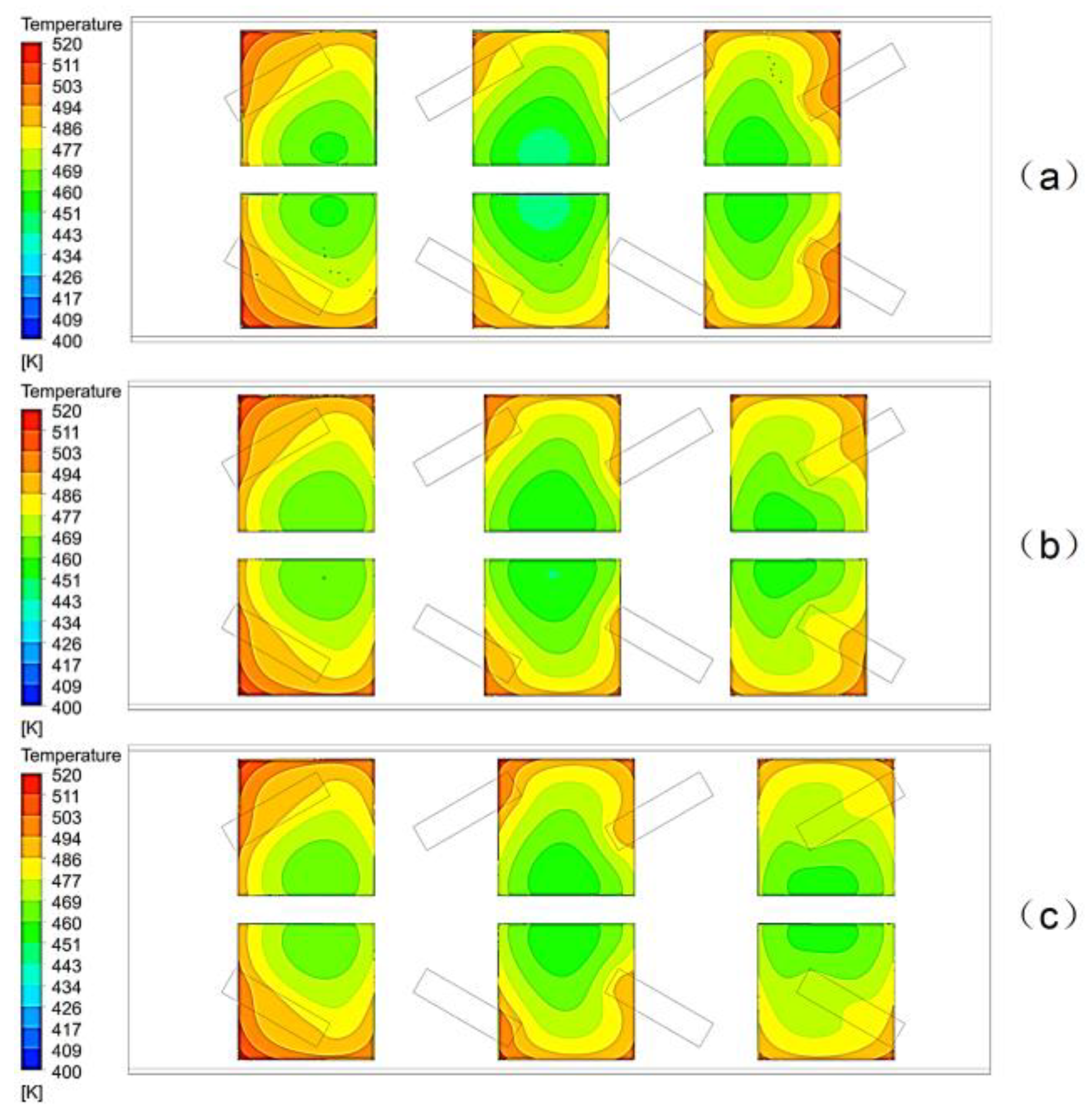
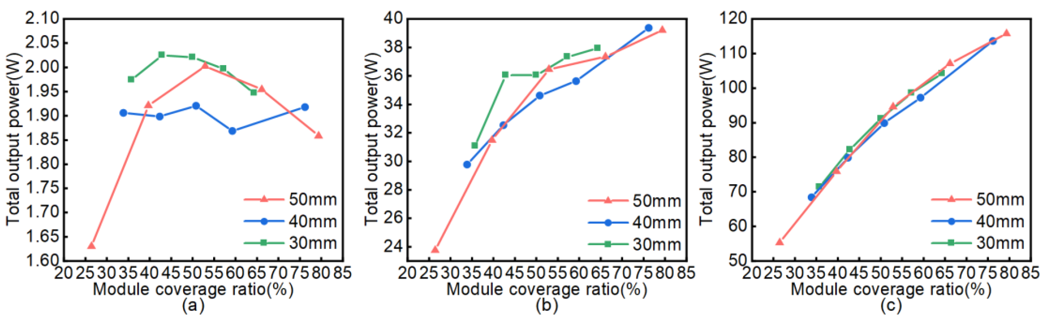
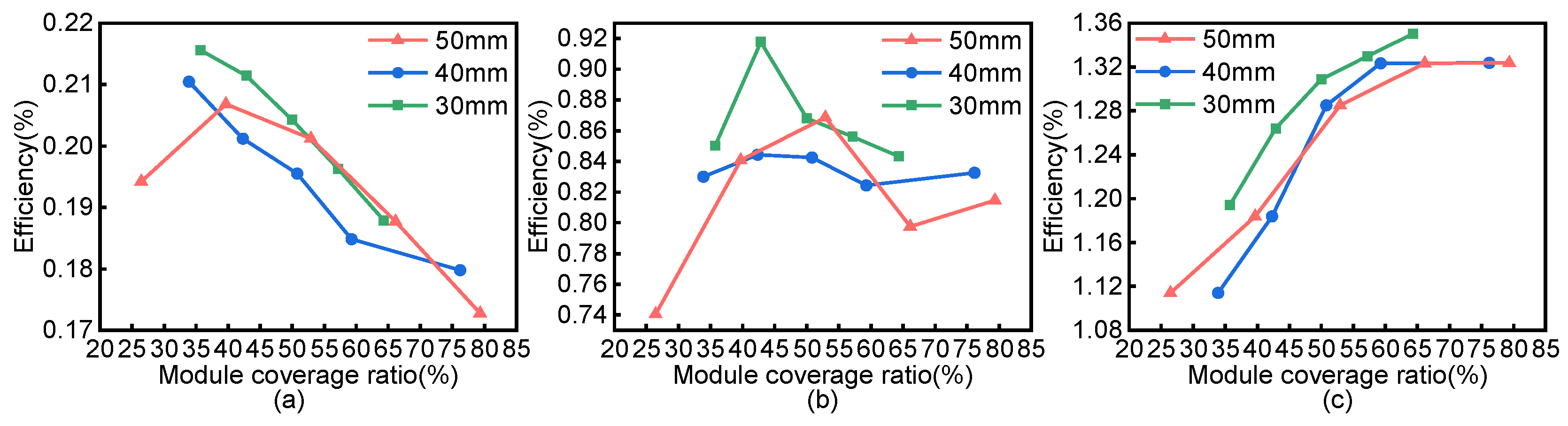
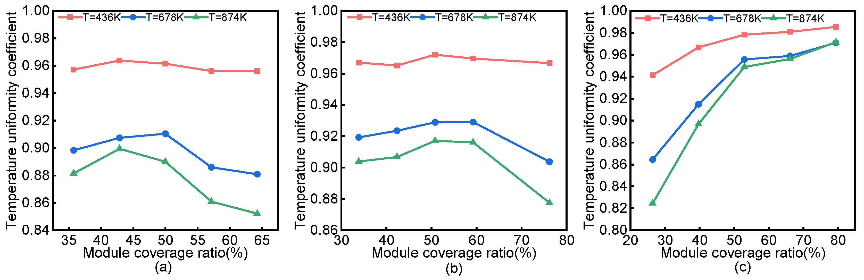
3.2. Research on Module Coverage

Five different coverage ratios (i.e., the ratio of the total modular area to the surface area of the hot side) were selected for each type of module, with side lengths of 30 mm, 40 mm, and 50 mm, as shown in Table 3. Comparative studies were carried out under three different working conditions, and the results are shown in Figure 11. The results show that when the coverage ratio of modules of different sizes was similar, the total output power of the system showed little difference. Under low-temperature conditions (Tinlet = 436 K), with the increase in module coverage ratio, the total power underwent an initial rise and a subsequent fall, which resulted from the low temperature of the inlet gas. When the temperature of the inlet gas is low, the heat provided is quite limited. Under such a circumstance, a large number of modules will cause insufficient and uneven heat absorption of each module, resulting in a low temperature at the hot side and a decrease in the total output power of the system. When the module coverage ratio was about 55%, the total output power was relatively high. In fact, excessive module coverage under low-temperature conditions cannot increase the output power of the system. Under medium- and high-temperature conditions, the temperature of the inlet gas increased, which could provide more heat to modules. Thus, as the coverage ratio increased, the total output power of the modules also rose. This phenomenon was more obvious under high-temperature conditions.
As can be seen in Figure 11 and Figure 12, the overall trend of the efficiency curve is similar to that of the total power curve. Under low-temperature conditions, a higher coverage ratio of modules led to less efficient power generation. Under medium-temperature conditions, higher efficiency was obtained when the module coverage ratio was moderate. However, under high-temperature conditions, the power generation efficiency was positively correlated with the module coverage ratio.

Analysis of Temperature Uniformity

To allow the thermoelectric power generation system to generate a larger voltage, all thermoelectric power generation modules are usually connected in series. However, the output current of the entire thermoelectric power generation system is limited by the minimum current in the thermoelectric modules, resulting in an additional power loss. Studies have shown that improving the temperature uniformity of the hot side of a thermoelectric power generation system can effectively solve this problem. This study used the temperature uniformity coefficient γ , and its expression is as follows [25]:
γ = 1 1 n i = 1 n | T i T m e a n | T m e a n
where n is the number of thermoelectric power generation modules, T i is the average temperature of the area where the power generation module block i is located, and T m e a n is the average temperature at the hot side of the thermoelectric power generation system. When the temperature uniformity coefficient γ is close to 1, the temperature uniformity at the hot side is ideal.
It can be seen from Figure 13 that when the module coverage ratio is determined, the overall trends of the temperature uniformity coefficient under different working conditions are similar. Specifically, when the coverage ratio is set, the inlet gas temperature and velocity increase, which will reduce the temperature uniformity. For modules with side lengths of 30 mm and 40 mm, a larger coverage ratio led to a smaller temperature uniformity coefficient. This is because a higher coverage ratio indicates an increase in the number of modules and a decrease in the module spacing, which results in insufficient absorption of heat among the internal modules, a larger difference in temperature between modules, and, finally, a decrease in the temperature uniformity coefficient. This phenomenon was more obvious under high-temperature conditions. For modules with a side length of 50 mm, due to the larger size and higher module coverage ratio, the number of modules used was far less than for those with side lengths of 30 mm and 40 mm. Hence, the modules were not compacted, and the module spacing was not small, which contributed to a relatively uniform temperature distribution among the modules. This, therefore, suggests that larger-size modules can be selected to improve the temperature uniformity of the thermoelectric power generation system, thereby effectively increasing the output power of the system.
Compared with the existing research, the current study investigated the impact of module spacing on an automobile exhaust thermoelectric power generation system in greater detail, by considering the module spacing of differently sized modules. It was found that when the number of thermoelectric power generation modules is determined, a reasonable increase in the layout spacing can effectively increase the total output power of the power generation modules under different working conditions. Additionally, when the module coverage ratio is moderate, choosing larger-sized power generation modules can improve the temperature uniformity of the thermoelectric power generation system and increase the system’s output power.

4. Conclusions

In the current study, the results showed that when the number of thermoelectric modules is set, a reasonable increase in module spacing can effectively increase the total output power of the power generation system under different working conditions, which verifies the necessity of optimizing the arrangement of the thermoelectric modules. When the spacing was 35 mm, the output power of the modules was compared with that when the spacing was 5 mm. Under low-temperature conditions, the growth rate of the output power of modules of different sizes was about 24%; under medium-temperature conditions, the output power growth rate of modules of different sizes was between 16% and 19%; under high-temperature conditions, the output power growth rate of modules of different sizes was between 8% and 9%. Under low-temperature conditions, the module coverage ratio should not be too high. Under medium- and high-temperature conditions, increasing the module coverage ratio can effectively increase the total output power of the system. The temperature uniformity of the hot side of the thermoelectric power generation system is closely related to the module coverage ratio and the temperature and speed of the inlet gas. Under low-temperature conditions, the temperature uniformity of modules is generally better. When the spacing between modules of 40 mm and 50 mm in size was set at around 35 mm, the power generation system achieves a relatively higher output power. Moreover, when the module coverage ratio was about 55%, the output power and temperature uniformity were more satisfactory. Future research can consider the impact of transverse spacing of modules on automotive exhaust thermoelectric power generation systems. More in-depth studies can be carried out on the module layout under transient conditions.

Author Contributions

W.Z., J.Y., Q.Q., J.Z., S.X., D.L. and R.W. contributed to the study’s conception and design. Material preparation, data collection, and analysis were performed by W.Z. and J.Y. The first draft of the manuscript was written by J.Y. and W.Z. J.Y., Q.Q., J.Z., S.X., D.L. and R.W. commented on previous versions of the manuscript. All authors have read and agreed to the published version of the manuscript.

Funding

This research was funded by the National Natural Science Foundation of China, Grant Number 51977100.

Institutional Review Board Statement

Not applicable.

Informed Consent Statement

Not applicable.

Data Availability Statement

Not applicable.

Acknowledgments

The authors are grateful for the financial support from the National Natural Science Foundation of China (51977100).

Conflicts of Interest

The authors declare that they have no conflict of interest.

References

  1. Champier, D. Thermoelectric generators: A review of applications. Energy Convers. Manag. 2017, 140, 167–181. [Google Scholar] [CrossRef]
  2. Yang, J.; Stabler, F.R. Automotive applications of thermoelectric materials. J. Electron. Mater. 2009, 38, 1245–1251. [Google Scholar] [CrossRef]
  3. Weng, C.C.; Huang, M.J. A simulation study of automotive waste heat recovery using a thermoelectric power generator. Int. J. Therm. Sci. 2013, 71, 302–309. [Google Scholar] [CrossRef]
  4. Bell, L.E. Cooling, Heating, Generating Heat with and Recovering Waste Thermoelectric. Science 2008, 321, 1457–1461. [Google Scholar] [CrossRef] [Green Version]
  5. Twaha, S.; Zhu, J.; Yan, Y.; Li, B. A comprehensive review of thermoelectric technology: Materials, applications, modelling and performance improvement. Renew. Sustain. Energy Rev. 2016, 65, 698–726. [Google Scholar] [CrossRef]
  6. Patyk, A. Thermoelectric generators for efficiency improvement of power generation by motor generators—Environmental and economic perspectives. Appl. Energy 2013, 102, 1448–1457. [Google Scholar] [CrossRef]
  7. Lee, H.S. Optimal design of thermoelectric devices with dimensional analysis. Appl. Energy 2013, 106, 79–88. [Google Scholar] [CrossRef]
  8. He, W.; Wang, S.; Yang, Y. Peak power evaluation and optimal dimension design of exhaust heat exchanger for different gas parameters in automobile thermoelectric generator. Energy Convers. Manag. 2017, 151, 661–669. [Google Scholar] [CrossRef]
  9. Yazawa, K.; Koh, Y.R.; Shakouri, A. Optimization of thermoelectric topping combined steam turbine cycles for energy economy. Appl. Energy 2013, 109, 1–9. [Google Scholar] [CrossRef]
  10. Min, G.; Rowe, D.M. Optimisation of thermoelectric module geometry for “waste heat” electric power generation. J. Power Sources 1992, 38, 253–259. [Google Scholar] [CrossRef]
  11. Kumar, S.; Heister, S.D.; Xu, X.; Salvador, J.R. Optimization of Thermoelectric Components for Automobile Waste Heat Recovery Systems. J. Electron. Mater. 2015, 44, 3627–3636. [Google Scholar] [CrossRef]
  12. Shen, L.; Zhang, W.; Liu, G.; Tu, Z.; Lu, Q.; Chen, H.; Huang, Q. Performance enhancement investigation of thermoelectric cooler with segmented configuration. Appl. Therm. Eng. 2020, 168, 114852. [Google Scholar] [CrossRef]
  13. Nemati, A.; Nami, H.; Yari, M.; Ranjbar, F. Effet de la géométrie et des courants appliqués sur l’exergie et la performance exergo-économique d’un refroidisseur thermoélectrique bi-étagé en cascade. Int. J. Refrig. 2018, 85, 1–12. [Google Scholar] [CrossRef]
  14. Shittu, S.; Li, G.; Zhao, X.; Ma, X. Series of detail comparison and optimization of thermoelectric element geometry considering the PV effect. Renew. Energy 2019, 130, 930–942. [Google Scholar] [CrossRef]
  15. Lamba, R.; Kaushik, S.C. Thermodynamic analysis of thermoelectric generator including influence of Thomson effect and leg geometry configuration. Energy Convers. Manag. 2017, 144, 388–398. [Google Scholar] [CrossRef]
  16. Fabián-Mijangos, A.; Min, G.; Alvarez-Quintana, J. Enhanced performance thermoelectric module having asymmetrical legs. Energy Convers. Manag. 2017, 148, 1372–1381. [Google Scholar] [CrossRef]
  17. Karana, D.R.; Sahoo, R.R. Influence of geometric parameter on the performance of a new asymmetrical and segmented thermoelectric generator. Energy 2019, 179, 90–99. [Google Scholar] [CrossRef]
  18. Hodes, M. Optimal pellet geometries for thermoelectric power generation. IEEE Trans. Compon. Packag. Technol. 2010, 33, 307–318. [Google Scholar] [CrossRef]
  19. Dongxu, J.; Zhongbao, W.; Pou, J.; Mazzoni, S.; Rajoo, S.; Romagnoli, A. Geometry optimization of thermoelectric modules: Simulation and experimental study. Energy Convers. Manag. 2019, 195, 236–243. [Google Scholar] [CrossRef]
  20. Luo, D.; Wang, R.; Yu, W.; Zhou, W. Parametric study of a thermoelectric module used for both power generation and cooling. Renew. Energy 2020, 154, 542–552. [Google Scholar] [CrossRef]
  21. Kim, T.Y.; Kwak, J.; Kim, B.W. Energy harvesting performance of hexagonal shaped thermoelectric generator for passenger vehicle applications: An experimental approach. Energy Convers. Manag. 2018, 160, 14–21. [Google Scholar] [CrossRef]
  22. Thacher, E.F.; Helenbrook, B.T.; Karri, M.A.; Richter, C.J. Testing of an automobile exhaust thermoelectric generator in a light truck. Proc. Inst. Mech. Eng. Part D J. Automob. Eng. 2007, 221, 95–107. [Google Scholar] [CrossRef]
  23. Crane, D.; Lagrandeur, J.; Jovovic, V.; Ranalli, M.; Adldinger, M.; Poliquin, E.; Dean, J.; Kossakovski, D.; Mazar, B.; Maranville, C. TEG on-vehicle performance and model validation and what it means for further teg development. J. Electron. Mater. 2013, 42, 1582–1591. [Google Scholar] [CrossRef]
  24. Deng, Y.D.; Liu, X.; Chen, S.; Tong, N.Q. Thermal optimization of the heat exchanger in an automotive exhaust-based thermoelectric generator. J. Electron. Mater. 2013, 42, 1634–1640. [Google Scholar] [CrossRef]
  25. Luo, D.; Wang, R.; Yu, W.; Zhou, W. A numerical study on the performance of a converging thermoelectric generator system used for waste heat recovery. Appl. Energy 2020, 270, 115181. [Google Scholar] [CrossRef]
  26. Bai, S.; Lu, H.; Wu, T.; Yin, X.; Shi, X.; Chen, L. Numerical and experimental analysis for exhaust heat exchangers in automobile thermoelectric generators. Case Stud. Therm. Eng. 2014, 4, 99–112. [Google Scholar] [CrossRef] [Green Version]
  27. Vale, S.; Heber, L.; Coelho, P.J.; Silva, C.M. Parametric study of a thermoelectric generator system for exhaust gas energy recovery in diesel road freight transportation. Energy Convers. Manag. 2017, 133, 167–177. [Google Scholar] [CrossRef]
  28. Wang, Y.; Li, S.; Xie, X.; Deng, Y.; Liu, X.; Su, C. Performance evaluation of an automotive thermoelectric generator with inserted fins or dimpled-surface hot heat exchanger. Appl. Energy 2018, 218, 391–401. [Google Scholar] [CrossRef]
  29. Wang, Y.; Li, S.; Zhang, Y.; Yang, X.; Deng, Y.; Su, C. The influence of inner topology of exhaust heat exchanger and thermoelectric module distribution on the performance of automotive thermoelectric generator. Energy Convers. Manag. 2016, 126, 266–277. [Google Scholar] [CrossRef]
  30. Marvão, A.; Coelho, P.J.; Rodrigues, H.C. Optimization of a thermoelectric generator for heavy-duty vehicles. Energy Convers. Manag. 2019, 179, 178–191. [Google Scholar] [CrossRef]
  31. Pacheco, N.; Brito, F.P.; Vieira, R.; Martins, J.; Barbosa, H.; Goncalves, L.M. Compact automotive thermoelectric generator with embedded heat pipes for thermal control. Energy 2020, 197, 117154. [Google Scholar] [CrossRef]
  32. Fernández-Yañez, P.; Armas, O.; Capetillo, A.; Martínez-Martínez, S. Thermal analysis of a thermoelectric generator for light-duty diesel engines. Appl. Energy 2018, 226, 690–702. [Google Scholar] [CrossRef]
  33. Favarel, C.; Bédécarrats, J.P.; Kousksou, T.; Champier, D. Numerical optimization of the occupancy rate of thermoelectric generators to produce the highest electrical power. Energy 2014, 68, 104–116. [Google Scholar] [CrossRef]
  34. Favarel, C.; Bédécarrats, J.P.; Kousksou, T.; Champier, D. Experimental analysis with numerical comparison for different thermoelectric generators configurations. Energy Convers. Manag. 2016, 107, 114–122. [Google Scholar] [CrossRef]
  35. Li, X.; Xie, C.; Quan, S.; Shi, Y.; Tang, Z. Optimization of Thermoelectric Modules’ Number and Distribution Pattern in an Automotive Exhaust Thermoelectric Generator. IEEE Access 2019, 7, 72143–72157. [Google Scholar] [CrossRef]
  36. Thankakan, R.; Samuel Nadar, E.R. Investigation of novel thermoelectric sensor array configurations operating under non-uniform temperature distribution conditions for the measurement of maximum output power in an energy harvesting system. IET Sci. Meas. Technol. 2021, 15, 446–458. [Google Scholar] [CrossRef]
  37. Ezzitouni, S.; Fernández-Yáñez, P.; Rodríguez, L.S.; Armas, O.; de las Morenas, J.; Massaguer, E.; Massaguer, A. Electrical modelling and mismatch effects of thermoelectric modules on performance of a thermoelectric generator for energy recovery in diesel exhaust systems. Energies 2021, 14, 3189. [Google Scholar] [CrossRef]
  38. Wang, R.; Yu, W.; Meng, X. Performance investigation and energy optimization of a thermoelectric generator for a mild hybrid vehicle. Energy 2018, 162, 1016–1028. [Google Scholar] [CrossRef]
  39. Eldesoukey, A.; Hassan, H. 3D model of thermoelectric generator (TEG) case study: Effect of flow regime on the TEG performance. Energy Convers. Manag. 2019, 180, 231–239. [Google Scholar] [CrossRef]
  40. Liu, L. Simulation and Optimization of Heat Transfer Performance of Cold and Hot Side of Automobile Exhaust Temperature Difference Generator; CNKI, China National Knowledge Infrastructure: Beijing, China, 2018; Available online: https://wap.cnki.net/touch/web/Dissertation/Article/10555-1018279255.nh.html (accessed on 20 September 2021).
  41. Chen, W.H.; Lin, Y.X.; Chiou, Y.B.; Lin, Y.L.; Wang, X.D. A computational fluid dynamics (CFD) approach of thermoelectric generator (TEG) for power generation. Appl. Therm. Eng. 2020, 173, 115203. [Google Scholar] [CrossRef]
Figure 1. Thermoelectric power generation model: (a) thermoelectric power generation simulation model; (b) module spacing; (c) internal spoiler.
Energies 15 00987 g001
Figure 2. Grid independence.
Energies 15 00987 g002
Figure 3. Diagram of the hot-side temperature of the module with a side length of 30 mm: (a) the inlet gas temperature = 436 K; (b) the inlet gas temperature = 678 K; (c) the inlet gas temperature = 864 K.
Energies 15 00987 g003
Figure 4. Diagram of the hot-side temperature of the module with a side length of 40 mm: (a) the inlet gas temperature = 436 K; (b) the inlet gas temperature = 678 K; (c) the inlet gas temperature = 864 K.
Energies 15 00987 g004
Figure 5. Diagram of the hot-side temperature of the module with a side length of 50 mm: (a) the inlet gas temperature = 436 K; (b) the inlet gas temperature = 678 K; (c) the inlet gas temperature = 864 K.
Energies 15 00987 g005
Figure 6. Cloud chart of the hot-side temperature: (a) module spacing: 35 mm; (b) module spacing: 40 mm; (c) module spacing: 45 mm.
Energies 15 00987 g006
Figure 7. The relationship between module spacing and output power: (a) modules with a side length of 30 mm; (b) modules with a side length of 40 mm; (c) modules with a side length of 50 mm.
Energies 15 00987 g007
Figure 8. Output power growth rate: (a) modules with a side length of 30 mm; (b) modules with a side length of 40 mm; (c) modules with a side length of 50 mm.
Energies 15 00987 g008
Figure 9. Output power growth rate of modules with a spacing of 35 mm.
Energies 15 00987 g009
Figure 10. Relationship plot of module spacing and efficiency: (a) modules with a side length of 30 mm; (b) modules with a side length of 40 mm; (c) modules with a side length of 50 mm.
Energies 15 00987 g010
Figure 11. The relationship between module coverage ratio and total system output power: (a) the inlet gas temperature = 436 K; (b) the inlet gas temperature = 678 K; (c) the inlet gas temperature = 864 K.
Energies 15 00987 g011
Figure 12. The relationship plot of module coverage ratio and efficiency: (a) the inlet gas temperature = 436 K; (b) the inlet gas temperature = 678 K; (c) the inlet gas temperature = 864 K.
Energies 15 00987 g012
Figure 13. Temperature uniformity coefficient of modules with different coverage ratios: (a) modules with a side length of 30 mm; (b) modules with a side length of 40 mm; (c) modules with a side length of 50 mm.
Energies 15 00987 g013
Table 1. Parameters of the thermoelectric power generation module.
ParametersNumerical ValueUnit
P TypeSeebeck coefficient ( 5.921376 × 10 13 ) × T 3 ( 3.274207 × 10 9 ) × T 2 + ( 2.422355 × 10 6 ) × T 2.743842 × 10 4 V · K 1
Resistivity ( 2.248899 × 10 14 ) × T 3 ( 1.250867 × 10 10 ) × T 2 + ( 1.388189 × 10 7 ) × T 2.244786 × 10 5 Ω · m
Thermal conductivity ( 1.251606 × 10 7 ) × T 3 ( 1.242845 × 10 4 ) × T 2 + ( 3.873788 × 10 2 ) × T 2.362707 W / ( m · K )
N TypeSeebeck coefficient ( 1.291689 × 10 13 ) × T 3 + ( 1.074408 × 10 9 ) × T 2 ( 9.271759 × 10 7 ) × T + 8.95888 × 10 6 V · K 1
Resistivity ( 1.24614 × 10 14 ) × T 3 ( 6.429015 × 10 11 ) × T 2 + ( 9.103036 × 10 8 ) × T 1.049646 × 10 5 Ω · m
Thermal conductivity ( 1.592653 × 10 8 ) × T 3 + ( 2.905845 × 10 5 ) × T 2 ( 1.58323 × 10 2 ) × T + 3.727526 W / ( m · K )
Table 2. Gas parameters under three working conditions.
ParameterWorking Condition IWorking Condition IIWorking Condition IIIParameter Unit
Inlet gas velocity73065 m / s
Inlet gas temperature436678864K
Density0.80760.51960.4187 kg / m 3
Specific heat capacity1018.61070.41113.8 J / ( kg · K )
Thermal conductivity0.03670.05210.062 W / ( m · K )
Dynamic viscosity2.44843.323713.8821 10 5   Pa · S
Table 3. Coverage ratio of modules of different sizes.
Scheme 1Scheme 2Scheme 3Scheme 4Scheme 5
Modules with a side length of 30 mmModule number1518212427
Coverage ratio35.71%42.86%50.00%57.14%64.29%
Modules with a side length of 40 mmModule number810121418
Coverage ratio33.86%42.33%50.79%59.26%76.19%
Modules with a side length of 50 mmModule number4681012
Coverage ratio26.46%39.68%52.91%66.14%79.37%
Publisher’s Note: MDPI stays neutral with regard to jurisdictional claims in published maps and institutional affiliations.

