
A Redesign Methodology to Improve the Performance of a Thermal Energy Storage with Phase Change Materials: A Numerical Approach

 , ,
, ,  and
and 
Abstract
:1. Introduction
2. Description of the Thermal Energy Storage System for Redesign
3. Improvement Opportunities for a Redesign
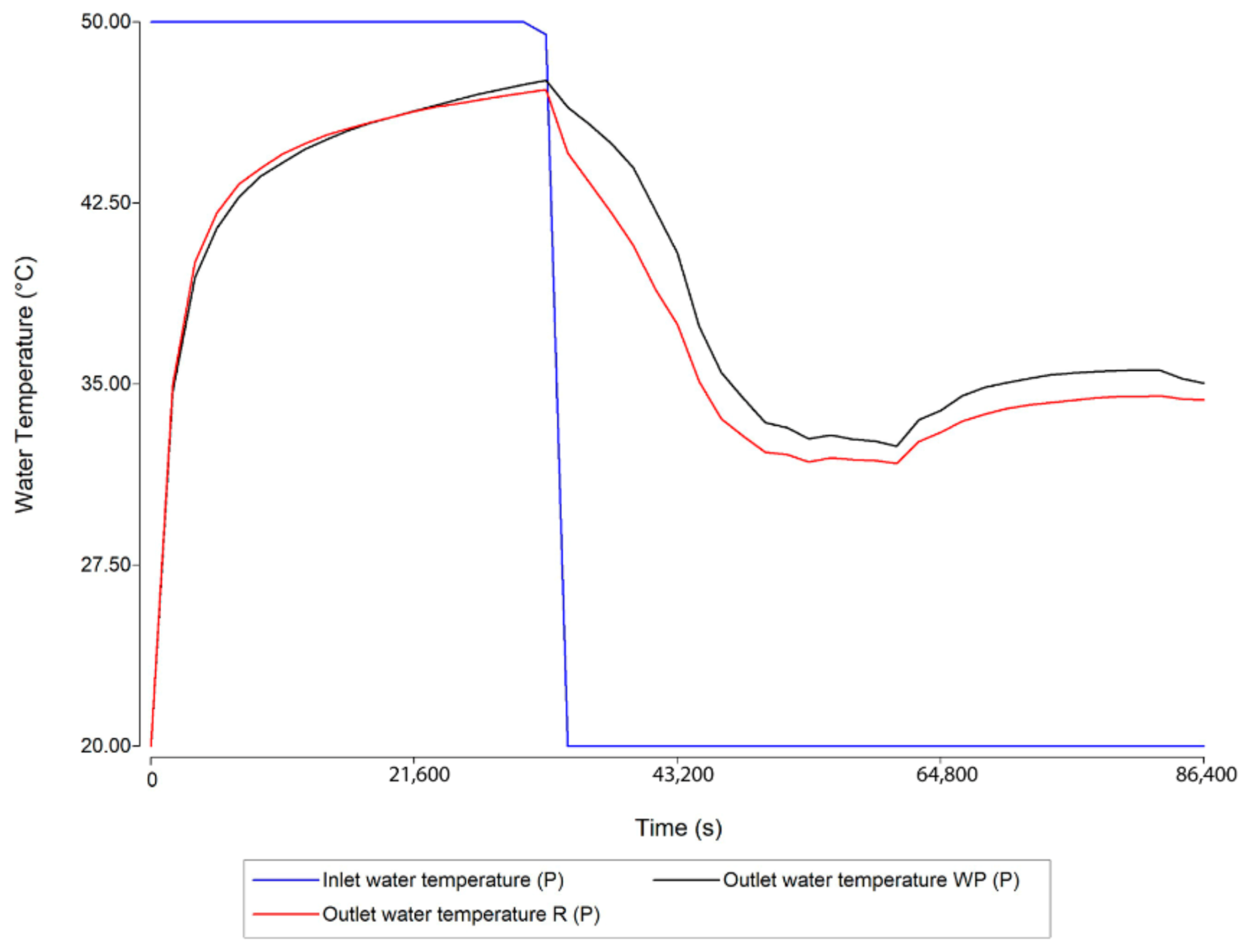
- In the reference study, the TES with PCM was not compared to the case without PCM (WP-TES) to evaluate whether the PCM improves the performance. The presence of PCM does not guarantee improvement in the system’s performance [8,30,31]. The design should be evaluated for the case of only sensible heat storage material to define the current needs to enhance the performance with PCMs.
- The technical requirements are crucial when selecting a PCM for a specific application [32]. Therefore, it is necessary to set a minimum hot water outlet temperature goal based on the technical requirements and select a new PCM with a melting temperature near the minimum target temperature of the hot water according to the literature [19].
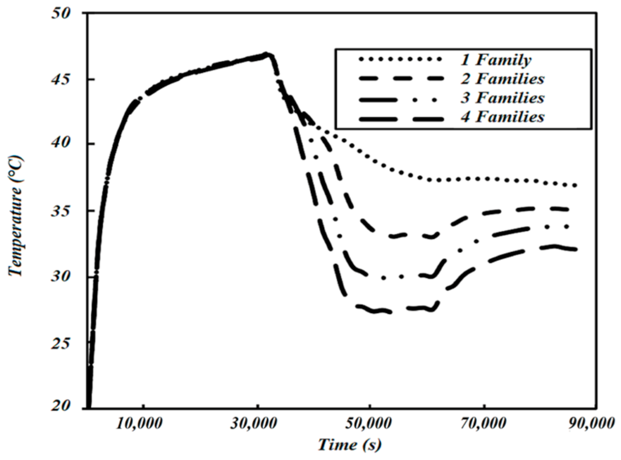
- In the reference study, neither of the flow rates selected could completely charge the PCM during the charging period (9 h). In addition, the PCM capsules were not completely solidified after any discharging period, which suggests the need to reevaluate the PCM amount [33] and encapsulation shape [34].
- The effect of the sensible heat storage material in the TES system is crucial because it consists of a well-balanced combination of latent and sensible heat storage materials [35]. Therefore, an improvement option consists of evaluating if water is the best option as a sensible heat storage material, and selecting another material on the contrary case [36]. The selected TES with PCM configuration allows considering a sensible storage material other than water due to the non-existence of contact between the hot drinking water and the TES materials [37].
4. Methodology
4.1. Step 1: Definition of Current Operating Conditions and Comparison of the Reference TES with the TES without PCM
4.2. Step 2: Selection of New PCM
4.3. Step 3: Evaluation of Geometry and Size of PCM Encapsulation
4.4. Step 4: Evaluation of Sensible Heat Storage Substance
5. Numerical Model
- The liquid phase is a Newtonian and incompressible fluid [13].
- The flow in the coil is laminar [13].
- The natural convection in the movement and behavior during the melting process is neglected for simplicity [15].
- The PCM encapsulation material does not affect the heat transfer rate between the sensible and latent heat storage substances, meaning it is considered to be entirely thermally conductive [15].
- The volume of the PCM does not experience changes during the phase transition [15].
- A stagnated substance surrounds the PCM prisms, and its velocity is zero [15].
- The velocity of PCM during the solid phase is zero even when surrounded by liquid [15].
- PCM is homogeneous and isotropic [34].
- The system is assumed stationary [53].
- PCM melting and solidifying temperatures are the same [54].
6. Results and Discussion
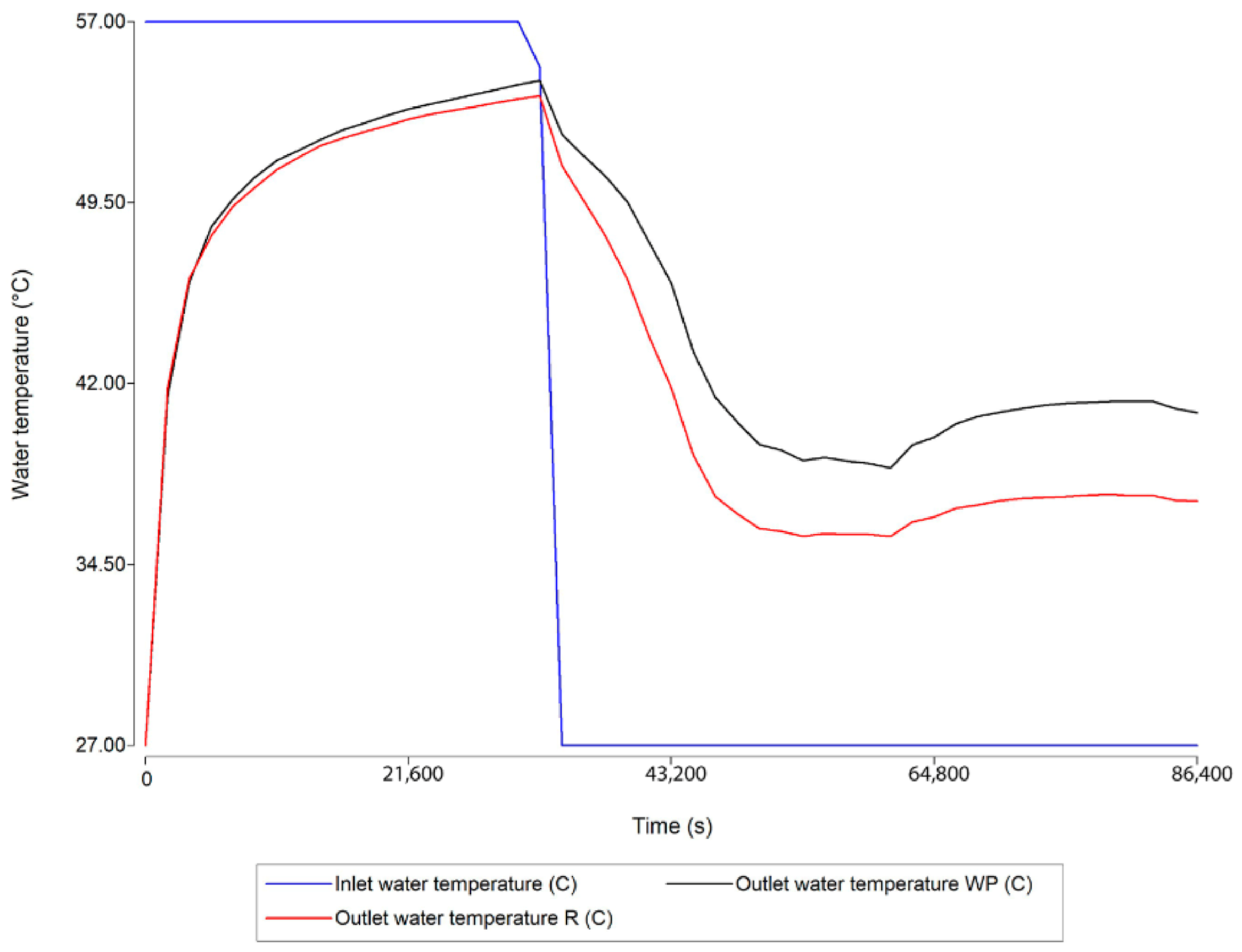
6.1. Implementation of Step 1: Definition of Current Operating Conditions and Comparison of the Reference TES with the TES without PCM
6.2. Implementation of Step 2: Selection of a New PCM
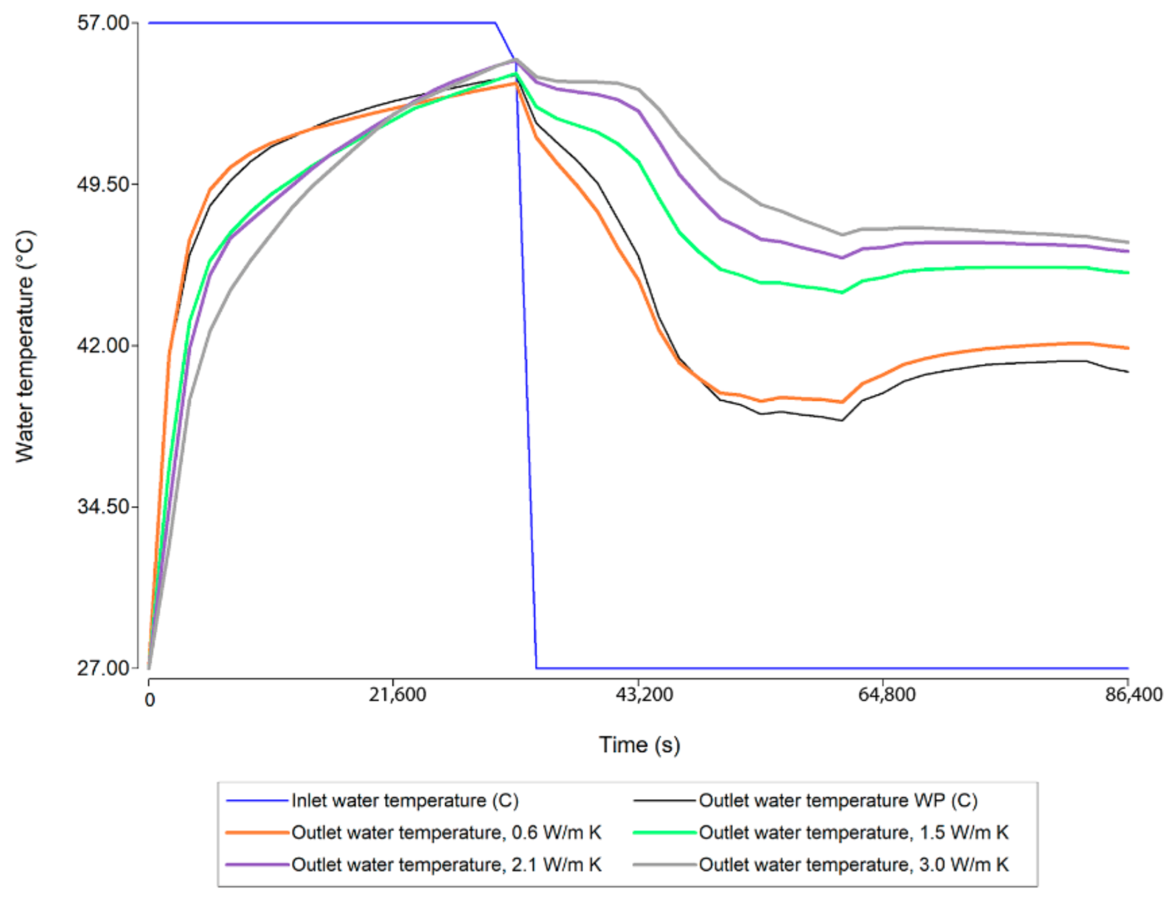
6.3. Implementation of Step 3: Evaluation of Geometry and Size of PCM Encapsulation
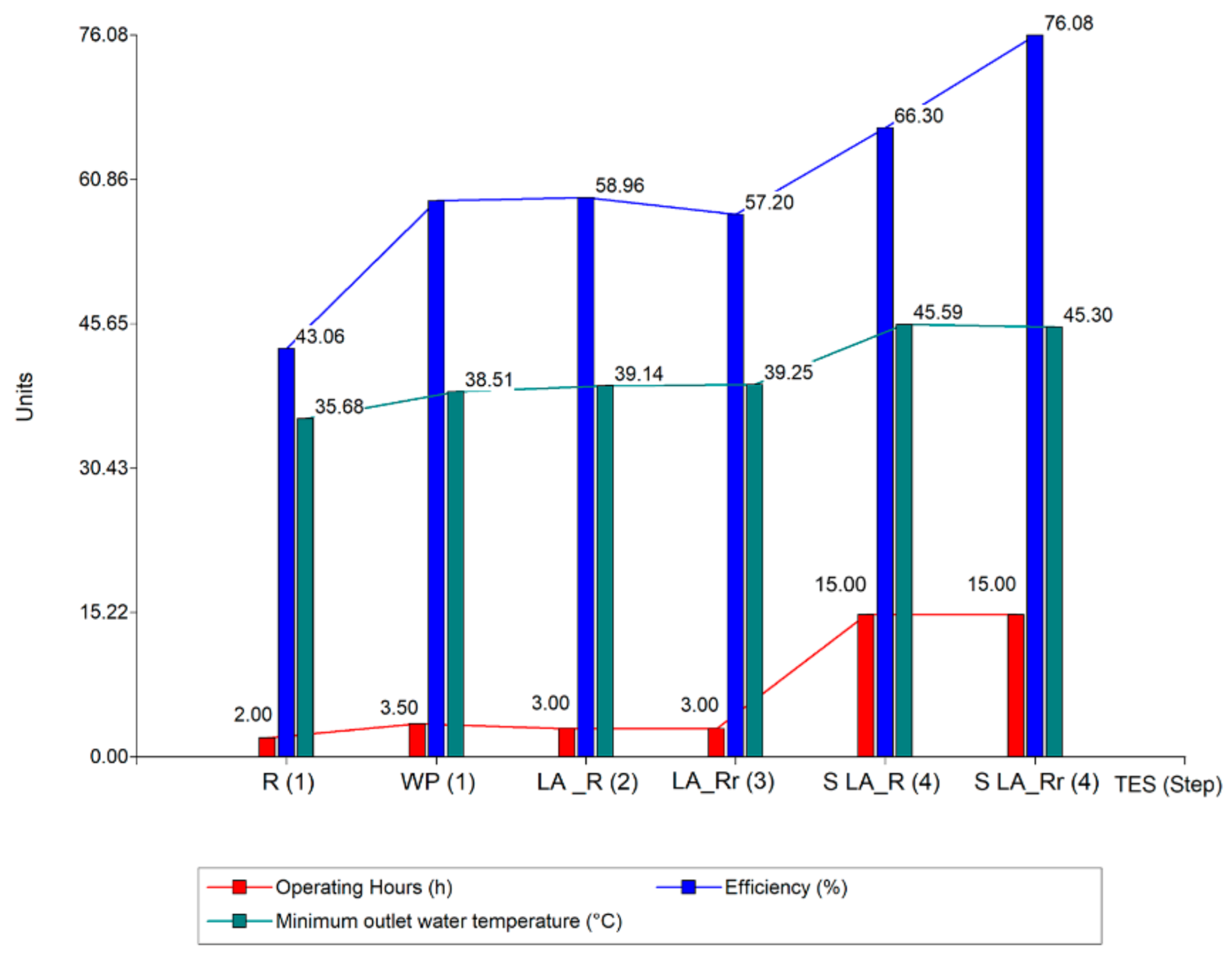
6.4. Implementation of Step 4: Evaluation of Sensible Heat Storage Substance
7. Conclusions and Future Work
Author Contributions
Funding
Institutional Review Board Statement
Informed Consent Statement
Data Availability Statement
Acknowledgments
Conflicts of Interest
References
- Kozlova, M. Real option valuation in renewable energy literature: Research focus, trends and design. Renew. Sustain. Energy Rev. 2017, 80, 180–196. [Google Scholar] [CrossRef]
- IRENA. Global Renewables Outlook: Energy Transformation 2050; International Renewable Energy Agency: Abu Dhabi, United Arab Emirates, 2020. [Google Scholar]
- IRENA. IRENA’s Energy Transition Support to Strengthen Climate Action; International Renewable Energy Agency: Abu Dhabi, United Arab Emirates, 2021. [Google Scholar]
- Naghavi, M.S.; Ong, K.S.; Badruddin, I.A.; Metselaar, H.S.C.; Mehrali, M.; Akhiani, A.R. Solar hot water production by using latent heat storage under tropical conditions. In Proceedings of the ISES Solar World Congress 2015, Daegu, Korea, 8–12 November 2015; pp. 1–12. [Google Scholar] [CrossRef]
- Liu, Z.; Wang, Z.; Ma, C. An experimental study on heat transfer characteristics of heat pipe heat exchanger with latent heat storage. Part I: Charging only and discharging only modes. Energy Convers. Manag. 2006, 47, 944–966. [Google Scholar] [CrossRef]
- Khot, S.A.; Sane, N.K.; Gawali, B.S. Thermal Energy Storage using PCM for Solar Domestic Hot Water Systems: A Review. J. Inst. Eng. Ser. C 2012, 93, 171–176. [Google Scholar] [CrossRef]
- Naghavi, M.; Metselaar, H.; Ang, B.; Zamiri, G.; Esmailzadeh, A.; Nasiri-Tabrizi, B. A critical assessment on synergistic improvement in PCM based thermal batteries. Renew. Sustain. Energy Rev. 2020, 135, 110259. [Google Scholar] [CrossRef]
- Bouhal, T.; El Rhafiki, T.; Kousksou, T.; Jamil, A.; Zeraouli, Y. PCM addition inside solar water heaters: Numerical comparative approach. J. Energy Storage 2018, 19, 232–246. [Google Scholar] [CrossRef]
- Abhat, A. Low temperature latent heat thermal energy storage: Heat storage materials. Sol. Energy 1983, 30, 313–333. [Google Scholar] [CrossRef]
- Luu, M.T.; Milani, D.; Nomvar, M.; Abbas, A. Dynamic modelling and analysis of a novel latent heat battery in tankless domestic solar water heating. Energy Build. 2017, 152, 227–242. [Google Scholar] [CrossRef]
- Carmona, M.; Palacio, M. Thermal modelling of a flat plate solar collector with latent heat storage validated with experimental data in outdoor conditions. Sol. Energy 2018, 177, 620–633. [Google Scholar] [CrossRef]
- Wu, W.; Dai, S.; Liu, Z.; Dou, Y.; Hua, J.; Li, M.; Wang, X.; Wang, X. Experimental study on the performance of a novel solar water heating system with and without PCM. Sol. Energy 2018, 171, 604–612. [Google Scholar] [CrossRef]
- Bayomy, A.; Davies, S.; Saghir, Z. Domestic Hot Water Storage Tank Utilizing Phase Change Materials (PCMs): Numerical Approach. Energies 2019, 12, 2170. [Google Scholar] [CrossRef] [Green Version]
- Kılıçkap, S.; El, E.; Yıldız, C. Investigation of the effect on the efficiency of phase change material placed in solar collector tank. Therm. Sci. Eng. Prog. 2018, 5, 25–31. [Google Scholar] [CrossRef]
- Seitov, A.; Akhmetov, B.; Georgiev, A.G.; Kaltayev, A.; Popov, R.K.; Dzhonova-Atanasova, D.B.; Tungatarova, M.S. Numerical simulation of thermal energy storage based on phase change materials. Bulg. Chem. Commun. 2016, 48, 181–188. [Google Scholar]
- Işık, S.; Yıldız, C. Improving thermal energy storage efficiency of solar collector tanks by placing phase change materials in novel finned-type cells. Therm. Sci. Eng. Prog. 2020, 19, 100618. [Google Scholar] [CrossRef]
- Naghavi, M.; Ang, B.; Rahmanian, B.; Bazri, S.; Mahmoodian, R.; Metselaar, H. On-demand dynamic performance of a thermal battery in tankless domestic solar water heating in the tropical region. Appl. Therm. Eng. 2019, 167, 114790. [Google Scholar] [CrossRef]
- Cetina-Quiñones, A.; Xamán, J.; Bassam, A.; Soberanis, M.E.; Perez-Quintana, I. Thermo-economic analysis of a flat solar collector with a phase changing material under tropical climate conditions: Residential and industrial case. Appl. Therm. Eng. 2020, 182, 116082. [Google Scholar] [CrossRef]
- Kyriaki, E.; Stergiopoulos, S.; Papadopoulos, A.M. Phase change materials to increase the storage potential of solar thermal systems. In Proceedings of the 2019 4th International Conference on Smart and Sustainable Technologies (SpliTech), Split, Croatia, 18–21 June 2019; pp. 1–7. [Google Scholar] [CrossRef]
- Zhao, J.; Ji, Y.; Yuan, Y.; Zhang, Z.; Lu, J. Energy-Saving Analysis of Solar Heating System with PCM Storage Tank. Energies 2018, 11, 237. [Google Scholar] [CrossRef] [Green Version]
- Ge, H.; Li, H.; Mei, S.; Liu, J. Low melting point liquid metal as a new class of phase change material: An emerging frontier in energy area. Renew. Sustain. Energy Rev. 2013, 21, 331–346. [Google Scholar] [CrossRef]
- Kanimozhi, B.; Bapu, B.R.; Pranesh, V. Thermal energy storage system operating with phase change materials for solar water heating applications: DOE modelling. Appl. Therm. Eng. 2017, 123, 614–624. [Google Scholar] [CrossRef]
- Badiei, Z.; Eslami, M.; Jafarpur, K. Performance improvements in solar flat plate collectors by integrating with phase change materials and fins: A CFD modeling. Energy 2019, 192, 116719. [Google Scholar] [CrossRef]
- Addad, Y.; Abutayeh, M.; Abu-Nada, E. Effects of Nanofluids on the Performance of a PCM-Based Thermal Energy Storage System. J. Energy Eng. 2017, 143, 04017006. [Google Scholar] [CrossRef]
- Kumar, P.M.; Mylsamy, K. A comprehensive study on thermal storage characteristics of nano-CeO2 embedded phase change material and its influence on the performance of evacuated tube solar water heater. Renew. Energy 2020, 162, 662–676. [Google Scholar] [CrossRef]
- Kee, S.Y.; Munusamy, Y.; Ong, K.S. Review of solar water heaters incorporating solid-liquid organic phase change materials as thermal storage. Appl. Therm. Eng. 2017, 131, 455–471. [Google Scholar] [CrossRef]
- Mofijur, M.; Mahlia, T.M.I.; Silitonga, A.S.; Ong, H.C.; Silakhori, M.; Hasan, M.H.; Putra, N.; Rahman, S.M.A. Phase Change Materials (PCM) for Solar Energy Usages and Storage: An Overview. Energies 2019, 12, 3167. [Google Scholar] [CrossRef] [Green Version]
- Fairey, P.; Parker, D. A Review of Hot Water Draw Profiles Used in Performance Analysis of Residential Domestic Hot Water Systems. Fla. Sol. Energy Cent. 2004, 2, 8. [Google Scholar]
- ASME. Performance Requirements for Water Temperature Limiting Devices 2020. Available online: https://www.plumbingfoundation.nyc/wp-content/uploads/2014/10/Summary-Plumbing-Code.Dec_.31.2014.pdf (accessed on 19 September 2021).
- Padovan, R.; Manzan, M. Development of a stratified tank storage component for ESP-r with embedded phase change material modules. Proc. Inst. Mech. Eng. Part A J. Power Energy 2013, 1, 56–61. [Google Scholar] [CrossRef]
- Porteiro, J.; Míguez, J.L.; Crespo, B.; De Lara, J.; Pousada, J.M. On the Behavior of Different PCMs in a Hot Water Storage Tank against Thermal Demands. Materials 2016, 9, 213. [Google Scholar] [CrossRef] [PubMed] [Green Version]
- Haillot, D.; Franquet, E.; Gibout, S.; Bédécarrats, J.-P. Optimization of solar DHW system including PCM media. Appl. Energy 2012, 109, 470–475. [Google Scholar] [CrossRef]
- Padovan, R.; Manzan, M. Genetic optimization of a PCM enhanced storage tank for Solar Domestic Hot Water Systems. Sol. Energy 2014, 103, 563–573. [Google Scholar] [CrossRef]
- Patel, J.R.; Joshi, V.; Rathod, M.K. Thermal performance investigations of the melting and solidification in differently shaped macro-capsules saturated with phase change material. J. Energy Storage 2020, 31, 101635. [Google Scholar] [CrossRef]
- Pizzolato, A.; Sharma, A.; Maute, K.; Sciacovelli, A.; Verda, V. Design of effective fins for fast PCM melting and solidification in shell-and-tube latent heat thermal energy storage through topology optimization. Appl. Energy 2017, 208, 210–227. [Google Scholar] [CrossRef]
- Fernandez, A.I.; Martínez, M.; Segarra, M.; Martorell, I.; Cabeza, L.F. Selection of materials with potential in sensible thermal energy storage. Sol. Energy Mater. Sol. Cells 2010, 94, 1723–1729. [Google Scholar] [CrossRef]
- Hussein, A.; Abd-Elhady, M.S.; El-Sheikh, M.N.; El-Metwally, H.T. Improving Heat Transfer Through Paraffin Wax, by Using Fins and Metallic Strips. Arab. J. Sci. Eng. 2017, 43, 4433–4441. [Google Scholar] [CrossRef]
- Harris, I.; Rosario, M.D.L.Á.O.D.; James, A.; Bruneau, D. Introduction to the application of phase change materials under tropical climate of Panama. In Proceedings of the 2019 7th International Engineering, Sciences and Technology Conference (IESTEC), Panama, Panama, 9–11 October 2019; pp. 177–182. [Google Scholar] [CrossRef]
- Termosolar Panamá. Análisis del Potencial de Desarrollo del Mercado de Calentadores Solares de Agua en Panamá; Termosolar Panamá: Clayton, Panama, 2019. [Google Scholar]
- Rozanna, D.; Chuah, T.G.; Salmiah, A.; Choong, T.S.Y.; Sa’ari, M. Fatty Acids as Phase Change Materials (PCMs) for Thermal Energy Storage: A Review. Int. J. Green Energy 2005, 1, 495–513. [Google Scholar] [CrossRef]
- Zuo, J.; Li, W.; Weng, L. Thermal properties of lauric acid/1-tetradecanol binary system for energy storage. Appl. Therm. Eng. 2011, 31, 1352–1355. [Google Scholar] [CrossRef]
- Bayram, U.; Aksöz, S.; Maraşlı, N. Temperature dependency of thermal conductivity of solid phases for fatty acids. J. Therm. Anal. 2014, 118, 311–321. [Google Scholar] [CrossRef]
- RubiTherm. Datasheet RT44HC. 9 October 2020. Available online: https://www.rubitherm.eu/media/products/datasheets/Techdata_-RT44HC_EN_09102020.PDF (accessed on 12 August 2021).
- Axiotherm. Datasheet ATP43. 2018. Available online: www.axiotherm.de (accessed on 12 August 2021).
- Gadhave, P.; Prabhune, C.; Pathan, F. Selection of Phase Change Material for Domestic Water Heating Using Multi Criteria Decision Approach. Aust. J. Mech. Eng. 2020, 1–21. [Google Scholar] [CrossRef]
- Martínez-Gómez, J.; Urresta, E.; Gaona, D.; Guerrón, G. Selection of Phase Change Materials for Latent Heat Storage. Revista Técnica Energía 2017, 13. [Google Scholar] [CrossRef]
- Kumar, R.; Jagadish; Ray, A. Selection of Material for Optimal Design Using Multi-criteria Decision Making. Procedia Mater. Sci. 2014, 6, 590–596. [Google Scholar] [CrossRef] [Green Version]
- Ebadi, S.; Tasnim, S.H.; Aliabadi, A.A.; Mahmud, S. Melting of nano-PCM inside a cylindrical thermal energy storage system: Numerical study with experimental verification. Energy Convers. Manag. 2018, 166, 241–259. [Google Scholar] [CrossRef]
- Dzikevics, M.; Ansone, A.; Blumberga, D. Modelling of Phase Change in Spheres for Applications in Solar Thermal Heat Storage Systems. Energy Procedia 2016, 95, 112–118. [Google Scholar] [CrossRef] [Green Version]
- Abokersh, M.H.; Osman, M.; El-Baz, O.; El-Morsi, M.; Sharaf, O. Review of the phase change material (PCM) usage for solar domestic water heating systems (SDWHS). Int. J. Energy Res. 2017, 42, 329–357. [Google Scholar] [CrossRef]
- Alwaeli, A.H.A.; Kazem, H.A.; Chaichan, M.T.; Sopian, K. Experimental investigation of using nano-PCM/nanofluid on a photovoltaic thermal system (PVT): Technical and economic study. Therm. Sci. Eng. Prog. 2019, 11, 213–230. [Google Scholar] [CrossRef]
- IAPWS. Revised Release on the IAPWS Formulation 1995 for the Thermodynamic Properties of Ordinary Water Substance for General and Scientific Use. 2018. Available online: http://iapws.org/relguide/IAPWS95-2018.pdf (accessed on 9 November 2021).
- Bird, R.B.; Stewart, W.E.; Lightfoot, E. Transport Phenomena, 2nd ed.; John Willey & Sons, Inc.: Hoboken, NJ, USA, 2002. [Google Scholar]
- He, B.; Martin, V.; Setterwall, F. Phase transition temperature ranges and storage density of paraffin wax phase change materials. Energy 2004, 29, 1785–1804. [Google Scholar] [CrossRef]
- Hu, T.; Li, Y.; Su, D.; Lv, H.X. Thermal Modeling Solid-Liquid Phase Change Materials (PCMs). Adv. Mater. Res. 2013, 746, 161–166. [Google Scholar] [CrossRef]
- COMSOL. Controlling the Time Dependent Solver Timesteps—Knowledge Base 2021. Available online: https://www.comsol.com/support/knowledgebase/1254 (accessed on 28 December 2021).
- Ray, A.K.; Rakshit, D.; Kumar, K.R.; Gurgenci, H. A Comparative Study of High-Temperature Latent Heat Storage Systems. Energies 2021, 14, 6886. [Google Scholar] [CrossRef]
- COMSOL. How to Inspect Your Mesh in COMSOL Multiphysics® COMSOL. 2017. Available online: https://www.comsol.com/blogs/how-to-inspect-your-mesh-in-comsol-multiphysics/ (accessed on 12 May 2017).
- PARKER Chomerics. Thermal Grease T650-T660-T670 Datasheet. 2021. Available online: https://www.parker.com/Literature/Chomerics/Catalogs/Thermal%20Grease%20T650-T660-T670.pdf (accessed on 19 September 2021).
- GNPGraystar. Thermal Properties of Ceramics. 2021. Available online: https://gnpgraystar.com/wp-content/uploads/2020/05/ThermalPropertiesofCeramicsGraphic.pdf (accessed on 19 September 2021).
- Islam, M.R.; Shabani, B.; Rosengarten, G. Electrical and Thermal Conductivities of 50/50 Water-ethylene Glycol Based TiO2 Nanofluids to be Used as Coolants in PEM Fuel Cells. Energy Procedia 2017, 110, 101–108. [Google Scholar] [CrossRef]
- Digi-Key Electronics. 65-00-T670-00014. 2021. Available online: https://www.digikey.es/product-detail/en/parker-chomerics/65-00-T670-00014/1944-1127-ND/9350016 (accessed on 3 October 2021).
- Jidhesh, P.; Arjunan, T.; Rathnaraj, J.D. Experimental investigation on heat transfer characteristics of phase change composite for thermal energy storage system. Mater. Today Proc. 2020, 42, 618–625. [Google Scholar] [CrossRef]


| N-Eicosane | Solid Phase | Liquid Phase |
|---|---|---|
| Melting point (°C) | 36.4 | |
| Latent heat (kJ/kg) | 247.3 | |
| Thermal conductivity (W/m·K) | 0.35 | 0.15 |
| Specific Heat (kJ/kg·K) | 2.1360 | 2.1336 |
| Density (kg/m3) | 856 | 778 |
| Operating Conditions and Targets | Reference TES | Redesigned TES |
|---|---|---|
| Inlet hot water temperature during charging time | 50 °C | 57 °C |
| Inlet cold water temperature during discharging time) | 20 °C | 27 °C |
| Charging time | 9 h | 9 h |
| Discharging time | 15 h | 15 h |
| Minimum temperature during discharging time (15 h) | Does not apply | 43 °C |
| Number of families | 1, 2, 3 and 4 | 2 |
| Minimum efficiency | Not defined | 60% |
| Material | A. Thermal Conductivity (W/m · K) | B. Specific Heat (kJ/kg · K) | C. Latent Heat (kJ/kg) | D. Melting Temperature (°C) | E. Density (kg/m3) | |||
|---|---|---|---|---|---|---|---|---|
| Liquid | Solid | Liquid | Solid | Liquid | Solid | |||
| 1. Lauric Acid [40,41,42] | 0.15 | 0.37 | 2.154 | 2.1416 | 182.92 | 43.9 | 870 | 1.007 |
| 2. RT44 [43] | 0.2 | 0.2 | 2 | 2 | 250 | 43 | 700 | 800 |
| 3. ATP 43 [44] | 0.2 | 0.2 | 2 | 2 | 265 | 43 | 760 | 780 |
| Parameters | R | WP | ||
|---|---|---|---|---|
| Previous | Current | Previous | Current | |
| Accumulated energy during charging time (kJ) | 21,438.83 | 23,435.74 | 21,938.15 | 21,992.92 |
| Delivered energy during discharging time (kJ) | 12,319.92 | 10,091.53 | 13,778.93 | 12,890.47 |
| Efficiency (%) | 57.47 | 43.06 | 62.81 | 58.61 |
| Maximum outlet water temperature during charging time (°C) | 44.58 | 51.05 | 46.47 | 52.35 |
| Minimum outlet water temperature during dicharging time (°C) | 34.35 | 35.68 | 35.04 | 38.51 |
| Operating hours (Outlet water temperature higher than 43 °C) | 1 | 2 | 2 | 3.5 |
| Parameters | R | WP | |
|---|---|---|---|
| N-E | LA | ||
| Accumulated energy during charging time (kJ) | 23,435.74 | 21,342.06 | 21,992.92 |
| Released energy during discharging time (kJ) | 10,091.53 | 12,749.78 | 12,890.47 |
| Efficiency (%) | 43.06 | 58.96 | 58.61 |
| Maximum outlet temperature during charging time (°C) | 51.05 | 51.30 | 52.35 |
| Minimum outlet water temperature during discharging time (°C) | 35.68 | 39.14 | 38.51 |
| Operating hours (Outlet water temperature over 43 °C) | 2 | 3 | 3.5 |
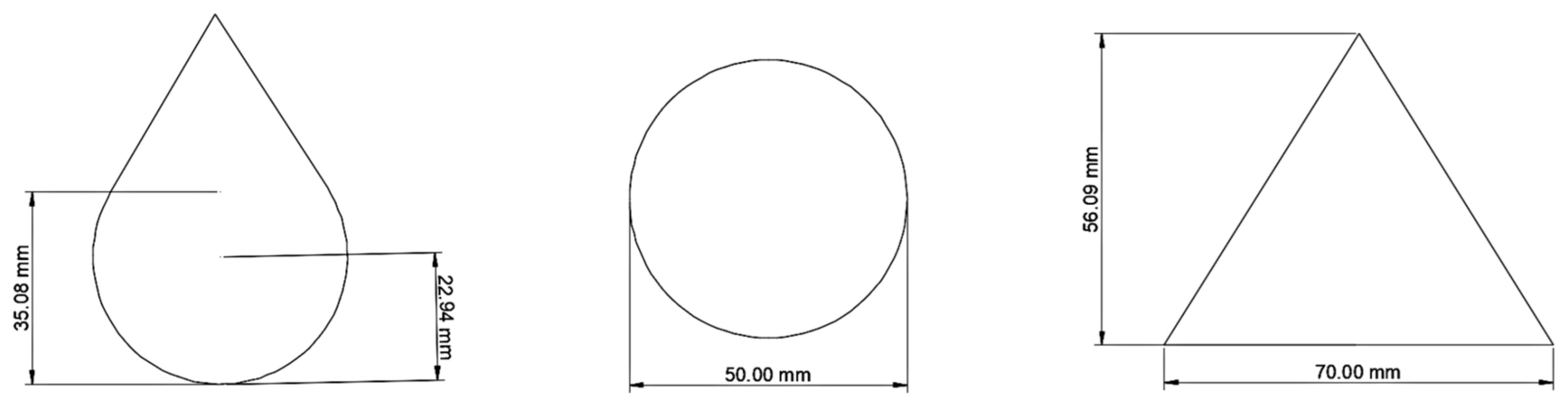
| Parameter | Cross-Section Shapes | |||
|---|---|---|---|---|
| Triangular | Drop | Circular | Circular without Central Elements (Approx. 3% Less PCM) | |
| Acummulated energy during charging time (kJ) | 21,111,56 | 21,180.21 | 21,342.06 | 21,527.19 |
| Maximum mean molten fraction in a cut-plane at the middle of the TES (pu) | 0.4695 | 0.4727 | 0.4788 | 0.5063 |
| Parameter | WP | LA_R | LA_Rr (Approx. 50% Less PCM) |
|---|---|---|---|
| Accumulated energy during charging time (kJ) | 21,992.92 | 21,342.06 | 22,012.70 |
| Delivered energy during discharging time (kJ) | 12,890.47 | 12,749.78 | 12,591.62 |
| Efficiency (%) | 58.61 | 58.96 | 57.20 |
| Maximum outlet water temperature during charging time (°C) | 52.35 | 51.30 | 51.48 |
| Minimum outlet water temperature during discharging time (°C) | 38.50 | 39.14 | 39.25 |
| Operating hours (Outlet water temperature over 43 °C) | 3.5 | 3 | 3 |
| Material | Thermal Conductivity (W/m · K) | Specific Heat (kJ/kg · K) | Density (kg/m3) | Sensible Heat Storage Capacity (kJ/m3 · K) |
|---|---|---|---|---|
| Water [52] | 0.623 | 4.182 | 997 | 4169.45 |
| Thermal grease T670 [59] | 3.000 | 1.000 | 2600 | 2600.00 |
| Steatite [60] | 3.300 | 0.980 | 2800 | 2.744 |
| 50% Ethylene Glycol—50% Water [61] | 0.282 | 3.480 | 1075 | 3.741 |
| Parameter | S-WP | S LA_R | S LA_Rr |
|---|---|---|---|
| Accumulated energy during charging time (kJ) | 19,357.12 | 28,116.01 | 25,470.68 |
| Delivered energy during discharging time (kJ) | 18,025.18 | 18,641.70 | 19,376.85 |
| Efficiency (%) | 93.12 | 66.30 | 76.08 |
| Maximum outlet water temperature during charging time (°C) | 56.86 | 55.13 | 55.94 |
| Minimum outlet water temperature during discharging time (°C) | 35.63 | 45.59 | 45.30 |
| Operating hours (Outlet water temperature over 43 °C) | 5.5 | 15 | 15 |
Publisher’s Note: MDPI stays neutral with regard to jurisdictional claims in published maps and institutional affiliations. |
© 2022 by the authors. Licensee MDPI, Basel, Switzerland. This article is an open access article distributed under the terms and conditions of the Creative Commons Attribution (CC BY) license (https://creativecommons.org/licenses/by/4.0/).
Share and Cite
Harris Bernal, I.A.; James Rivas, A.M.; Ortega Del Rosario, M.D.L.A.; Saghir, M.Z. A Redesign Methodology to Improve the Performance of a Thermal Energy Storage with Phase Change Materials: A Numerical Approach. Energies 2022, 15, 960. https://doi.org/10.3390/en15030960
Harris Bernal IA, James Rivas AM, Ortega Del Rosario MDLA, Saghir MZ. A Redesign Methodology to Improve the Performance of a Thermal Energy Storage with Phase Change Materials: A Numerical Approach. Energies. 2022; 15(3):960. https://doi.org/10.3390/en15030960
Chicago/Turabian StyleHarris Bernal, Itamar A., Arthur M. James Rivas, María De Los A. Ortega Del Rosario, and M. Ziad Saghir. 2022. "A Redesign Methodology to Improve the Performance of a Thermal Energy Storage with Phase Change Materials: A Numerical Approach" Energies 15, no. 3: 960. https://doi.org/10.3390/en15030960