Review

A Review of the Advancements in the Design of Brushless Doubly Fed Machines

by
Oreoluwa I. Olubamiwa
and
Nkosinathi Gule
*
Department of Electrical and Electronic Engineering, Stellenbosch University, Stellenbosch 7600, South Africa
*
Author to whom correspondence should be addressed.
Energies 2022, 15(3), 725; https://doi.org/10.3390/en15030725
Submission received: 18 November 2021 / Revised: 15 December 2021 / Accepted: 24 December 2021 / Published: 19 January 2022

Abstract

:
Research interest on brushless doubly fed induction machines (BDFMs) is increasing, as they offer higher reliability compared to doubly fed induction generators (DFIGs) in wind turbines. At the moment, BDFMs do not have a definitive structure nor design process, as literature is rife with different approaches to designing BDFMs. In this paper, a comprehensive review of the design of BDFMs from available literature is conducted. The evolution of cascade induction machine systems to contemporary BDFMs is first illustrated. Pioneering research work in the evolution which have influences on modern BDFM designs are highlighted. Relevant research on different aspects of present day BDFM design are then discussed. BDFM design and optimization methodologies applied in available literature are also explored.

1. Introduction

Doubly fed induction generators (DFIGs) are the most widely employed generators in medium and large wind turbines. This is due to their low cost, variable speed operations, and the use of fractionally rated converters in their setup [1]. However, DFIG based wind turbines have the highest operational and maintenance (O&M) costs, because of DFIG slip ring and brush assembly failures [2]. This is further compounded in remote areas like offshore wind sites, which have low accessibility. It is worth noting that offshore wind power is getting increasing attention, and a significant expansion in offshore wind installations is projected in the coming years [3].
Brushless doubly fed machines (BDFMs) have similar advantages with DFIGs, and the absence of slip ring and brush assemblies in their setup increases their reliability [4]. As a result, the O&M costs of wind turbines using BDFMs would potentially be reduced. However, BDFMs have complex structures with lower power densities, compared to DFIGs [5]. There is also no consensus regarding certain critical aspects of BDFM design.
The development of BDFMs can be traced to machines preceding DFIGs, and these machines were mostly used for motoring purposes. In this paper, the historical evolution of BDFMs is first outlined to paint a clear picture of the development of BDFM design. The influence of the shift from cascade motoring to doubly fed generating operations on BDFM features is discussed. A thematic review of published literature considering the design of contemporary BDFMs is then presented. The different BDFM components are comprehensively examined, as well as design and optimization procedures employed in literature. The overarching aim of this paper is to provide perspective on contemporary BDFM structures, and a comprehensive overview of BDFM design.
It is recognized that general reviews on BDFMs are available in literature such as [6,7,8]. These reviews cover a broad array of subjects like brief histories, electromagnetic design, modelling techniques, modes of operation, and control strategies. Consequently, the BDFM design considerations in these reviews are not exhaustive. Doubly fed reluctance machines are also discussed in these reviews. However, in this paper, there is a comprehensive focus on the design of BDFMs, and the procedures involved. Doubly fed machines with reluctance rotors, hybrid rotors and dual stators are not considered.
This paper is divided into two main sections:
  • The evolution of cascaded IMs to contemporary BDFM topologies. In this section, significant contributions to the present day BDFM topologies are highlighted, with the underlying reasons for these design developments.
  • Discussions on the aspects of BDFM design. A comprehensive run-down of recent developments and approaches employed in the design of BDFMs, are presented in this section.

2. Development of BDFMs from Cascade Induction Motors

At the turn of the 19th century, polyphase induction motors (IMs) were increasing in industry usage, due to their simplicity and reliability [9]. Squirrel cage induction motors (SCIMs) were preferred in environments like mining industries, where rough and rigorous handling of equipment were required [10]. However, SCIMs were only relevant for constant speed and moderate starting torque operations. This was before the advent of power electronics, and variable speed motoring operations commonly employed direct current motors [11,12]. Wound rotor (slip ring) induction motors using rheostatic control also seem to have been used for variable speed applications at the time [13,14]. Slip ring IM setups with rheostatic control had performances analogous to shunt motors [12], however with significant losses [15].
Cascade motors were developed in the pursuit of the robustness of SCIMs, and the variable speed functionality of slip ring IMs with rheostatic controls [10,14]. Cascade motor origins can be traced to cascade systems, which consisted of two or more motors having a common connecting shaft. A good example of these cascade systems is the Steinmetz cascade IM system, which was patented in 1897 [16]. These motors were connected according to different configurations to achieve different speed and power configurations. Examples of these connections are illustrated in Figure 1. In Figure 1a, the stator of the secondary motor is connected to the rotor of the primary motor. By this connection, a starting torque almost double one of the motors is achievable without the losses common with rheostatic controls. The connection in Figure 1b enables speed control capabilities similar to the series-parallel control of DC motors; Figure 1c likewise, with more options [16].
Cascade systems however had disadvantages of high cost, low efficiency, low power factor, and poor overload capacity [14]. Over time, different machines were designed with inspiration from cascade systems, from which modern day BDFMs were eventually developed. In the following subsections, distinct pioneering machines are highlighted, with their major contributions to the development of BDFMs underscored. A summary of the shift from cascade operations to synchronous doubly fed operations is also given.

2.1. The Thompson Motor

A motor patented by S. Thompson in 1901, was highlighted in [14] as essentially being equivalent to a two motor cascade. The stator was divided into segments occupied by the primary and secondary windings. Alternate segments had different windings preventing mutual induction, as illustrated in Figure 2. The primary windings were connected directly to the main supply, while the secondary windings were connected to regulating resistances. The rotor had a wave winding which coupled with the primary stator field and induced a field on the secondary stator winding. Placing all the windings on one core was to reduce the setup cost, as opposed to two separate machines connected in cascade. The Thompson motor helped shape the shift from multiple motors in a cascade system to a single motor with cascaded operations.

2.2. The Lydall Motor

A patent for a polyphase motor which could be operated at three speeds without rheostatic loss, was accepted in 1903 [13]. This motor was developed by the Siemens brothers & Co. Limited and Francis Lydall, with two stator windings which had different pole numbers preventing direct inductive coupling. The rotor also had two windings wound in similar fashion as the stator, with connections made possible by slip rings. A schematic illustration of the Lydall motor is given in Figure 3. In reality, the “switching controller” in Figure 3 consisted of 3 barrel switches used to achieve desired connections.
The synchronous speed of S1 was achieved by connecting the supply to S1, S2 to R1, and R2 to the starting rheostats; the synchronous speed of S2 was achieved by swapping these connections (S2 to the supply, S1 to R2, R1 to rheostats). A cascade speed was achieved by connecting S1 to the supply, shorting S2 and R2, and connecting R1 to the starting rheostats.
The difference in pole numbers made segmentation of the stator windings unnecessary, as one could be placed on top the other. However, there was increased copper losses from the two sets of windings (on the stator and rotor), and increased magnetic leakage due to deeper slots, especially from the winding farthest from the air-gap [14]. Despite this, it should be noted that present day BDFMs use the Lydall type of stator, with windings of different pole numbers; one on top of the other.

2.3. The Hunt Motor

L.J. Hunt introduced a cascade motor in [14], with single stator and rotor windings. This motor had regulating resistances connected to tappings on the stator winding, and did not need slip rings. Slip rings could however be employed if more efficient speeds were desired. The special stator winding allowed for reduction of magnetic leakage and copper losses incurred by the two stator windings in prior cascade motors. Hunt continued to work on the development of this motor, fine tuning the design and making it more practical.
Upon the successful construction and usage of large numbers of these machines, another paper [10] was published in 1914. This paper gave more details as to the design of the hunt motor, and also notably a brief guide into the selection of the number of poles on the stator. In Figure 4, the coil group connections to obtain 4 poles, 8 poles, and (4 + 8) poles configurations from a star wound single stator are illustrated. In 1921, F. Creedy published a paper [17], which shed more light on the pole number selections, paving the way for new combinations. Improved rotor and stator winding designs for this type of cascade motor were also discussed in [17]. The works of L.J. Hunt and F. Creedy were foundational for the selection of suitable pole pair combinations for BDFM stator windings.

2.4. The Broadway & Burbridge Motor

In [18], Broadway and Burbridge sought to design cascade motor rotors that were simpler compared to the irregularly grouped double layer wound rotors in the Hunt/Creedy motors. Two single layer winding rotors, the graded winding rotor and the multicircuit winding rotor, were investigated. The winding arrangements of these rotors are illustrated in Figure 5. Although, the coils of the graded winding rotor in Figure 5a are not short circuited together, the graded winding rotor prototype in Figure 6a has a common end-ring for all the coils. The graded winding rotor in Figure 6a is built for a (6 + 2) poles cascade machine. A multicircuit rotor for a (18 + 12) poles machine is also built in [18], as shown in Figure 6b. These rotors presented in [18], which are now more commonly called the nested loops (NL) and cage+NL rotors respectively, are currently the most widely used rotors in contemporary BDFMs.

2.5. Cascade Systems to Brushless Doubly Fed Operations

The cascade IM systems/cascade motors were conceived at a time before power electronic converters. Early cascade systems/motors were developed to achieve efficient motor operations at different (usually low) speeds. The cascade motors were also developed with the view of obtaining robustness and reliability similar to SCIMs [14,18].
The synchronous operation of machines similar to S. Thompson’s motor, were detailed by B.H. Smith in 1966-7 [19,20]. These motors used by B.H. Smith, were at the time called twin stator induction machines, and the stator windings were both fed with three phase supplies at different frequencies. This was the first of analyses of what were hitherto cascade motors, operating similarly to doubly fed induction machines. Slip frequency excitation from a low power frequency converter was discussed for harnessing slip power from the machine rotors.
In 1970 [18], Broadway and Burbridge also discussed the synchronous operations of cascade machines. However, these synchronous operations were limited to the machine synchronous speed, such that AC was applied to one stator winding, and DC to the other. Full load performances of the cascade machines in synchronous operations were notably superior to asynchronous operations of equivalent multipole IMs. Also, there was an increase in power factor compared to asynchronous operations.
The first traceable mention of the term “brushless doubly fed machine (BDFM)” is in [21], a 1989 paper about a dynamic model of BDFMs. In 1994, Brune et al. tested the possibilities of using BDFMs in a variable speed wind turbine in [22]. The use of a BDFM in a wind turbine was an attempt to obtain the benefits of a DFIG in with a more robust structure, which is still the main reason for the recent push in research about BDFMs. A 1.5 kW prototype was built to demonstrate the viability of BDFM based wind turbines. In the following sections, the discussion is shifted to recent (mainly post 90s) developments in the design of BDFMs. Research challenges with the design and approaches to solving these issues are also discussed.

3. Recent BDFM Design Development

In a push towards commercial MW rated BDFMs, the authors in [23] presented a 250 kW rated BDFM. This being the largest BDFM/BDFIG tested to date, showed expected performances and stable control, and thus the viability of the technology.
Although the BDFM is not yet at a commercial scale of implementation, the prospects of usage in wind turbines have piqued the interests of several research groups globally. As a result, a number of notable developments in the design of BDFMs have occurred. A large portion of these developments have had focusses on suitable pole pair combinations and optimum rotor design. Maximizing the power density and reduction of harmonics have also received their fair share of attention. Furthermore, different design approaches of BDFMs have been presented, and all these aspects are discussed in the subsequent sections.

3.1. Stator Winding Development

Up until around 1989, the L.J. Hunt type of stator windings [10] were used for BDFMs, in which coil groups were interconnected in a way to accommodate two AC supplies (or pole pairs) [21]. However in [24], it was suggested that the L.J. hunt type of stator winding was better suited for applications in which only one set of terminals were connected to a power source at a time.
For synchronous BDFM operations, with two AC supplies connected to the terminals, there are unbalances in the Hunt type of stator, which lead to internal circulating currents. Therefore, reverting to isolated stator windings like in the Lydall motor was recommended in [24]. This helped in avoiding the circulating currents, while affording greater simplicity and flexibility.
Consequently, contemporary BDFM stators have two isolated windings, the power winding (PW) and the control winding (CW). The stator windings do not couple directly, but are cross-coupled by a special rotor (see Section 3.2). As already suggested in [14], the winding which is farthest from the airgap has increased leakage. Placing the PW at the bottom layer would have significant effects on the converter ratings, as higher leakage would increase the difficulty in controlling the grid side power factor as noted in [25]. Thus, the PW with p 1 pole pairs typically occupies the bottom layer (closest to the airgap) of the stator slots, while the CW with p 2 pole pairs occupies the top layer. This type of stator for a p 1 / p 2 = 2/3 BDFM, is illustrated in Figure 7.

3.1.1. Relative Winding Pole Size

Typically, p 1 is lower than p 2 for a number of reasons. A significant reason for using the lower pole as p 1 is the higher magnetizing requirements with increasing poles [26,27,28]. Thus higher poles for p 1 can increase the power ratings of the converters used. Furthermore, the lower pole number for p 1 affords better winding distribution, as the PW and CW occupy the same number of slots, and this helps reduce unwanted harmonics.
The BDFM torque breaks down at the synchronous speed of a p 1 machine, thus favouring a lower p 1 for a wider operating speed range [27]. However, this hardly applies to BDFMs with regards to being alternatives to DFIGs in wind turbines. To use fractionally rated converters, the BDFM maximum speed will typically be lower than the synchronous speed of the higher pole [29].
The rotor field frequency ( ω r f ) is calculated from the formula in [30,31],
ω r f = ω 1 p 1 ω r = ω 2 + p 2 ω r ,
where, ω 1 & ω 2 are the electrical angular speeds of the PW and CW respectively, while ω r is mechanical angular speed of the rotor. It can be observed that ω r f is higher if p 1 is lower than p 2 . This leads to higher core losses [32,33], and rotor impedances considering that skin effect is lower at lower frequencies. The disparity between p 1 and p 2 should not be too high to reduce copper losses due to skin effect [32].

3.1.2. Unbalanced Magnetic Pull and Magnetic Coupling

In [34], it was established that when a x-pole pair field is combined with a ( x + y )-pole pair field, a force imbalance occurs when y = 1. This imbalance, now commonly called an unbalanced magnetic pull (UMP), was then illustrated (Figure 8) with a 2/3 pole pair combination. It can be observed from the force diagram in Figure 8, that a strong force zone is directly opposite to a weak zone, giving rise to the imbalance. If y > 1, there will be equal y strong and weak zones [34], and UMPs can be avoided.
The harmonics generated by the PW and CW are given respectively as
h p w = p 1 ( 2 t 1 ) , t N , h c w = p 2 ( 2 t 1 ) , t N .
If the windings have no common harmonic, they do not couple inductively. A bit more nuance about selecting pole pair combinations towards ensuring non coupling is provided in [30]. However, the rules given in [30] only apply when series windings are used. The use of parallel coil group connections can enable direct coupling of the PW and CW, which produces circulating currents. Practical connections of coil groups in parallel while avoiding direct coupling are discussed in [35], and these parallel paths can help mitigate UMPs.

3.1.3. Commonly Used Pole Pair Combinations

Pole pair combinations which do not produce UMPs were tested using 2D FE BDFM models in [36] to highlight suitable combinations. Although the p 1 / p 2 = 2 / 4 pole pair combination is used for a 250 kW BDFM prototype in [37], the results in [36] suggest that the p 1 / p 2 = 4 / 6 combination is more suitable in terms of power, efficiency and torque ripple. However, optimization results in [38] indicate that the p 1 / p 2 = 2 / 4 combination performs better than the p 1 / p 2 = 4 / 6 combination for a BDFM in a D180 frame size. Analytical estimations in [29] also point to better performance from the p 1 / p 2 = 2 / 4 combination, compared to the p 1 / p 2 = 4 / 6 in terms of power and efficiency.
In spite of these, the p 1 / p 2 = 2 / 3 is the preferred combination for the D180 frame BDFM in [38,39], as it produces the best performance in terms of efficiency and generated torque. The p 1 / p 2 = 2 / 3 combination in [38] also has considerably lower torque ripple and time harmonic distortions, compared to the p 1 / p 2 = 2 / 4 combination. Concerns of UMP with the p 1 / p 2 = 2 / 3 combinations were considered minor in [38], due to the small size of the machine. In [40], the p 1 / p 2 = 4 / 6 is the preferred combination for a 3.2 MW BDFM, due to the less coupling of higher space harmonics compared to the p 1 / p 2 = 2 / 4 combination, and the absence of UMP, which is present in the p 1 / p 2 = 2 / 3 combination. The lower harmonic content in the 4 / 6 combination relative to the 2 / 4 combination is also alluded to in [41], however the PW has the higher pole number. A summary of the relative performances of the 2 / 3 , 2 / 4 and 4 / 6 pole pair combinations as described in literature, is given in Table 1.

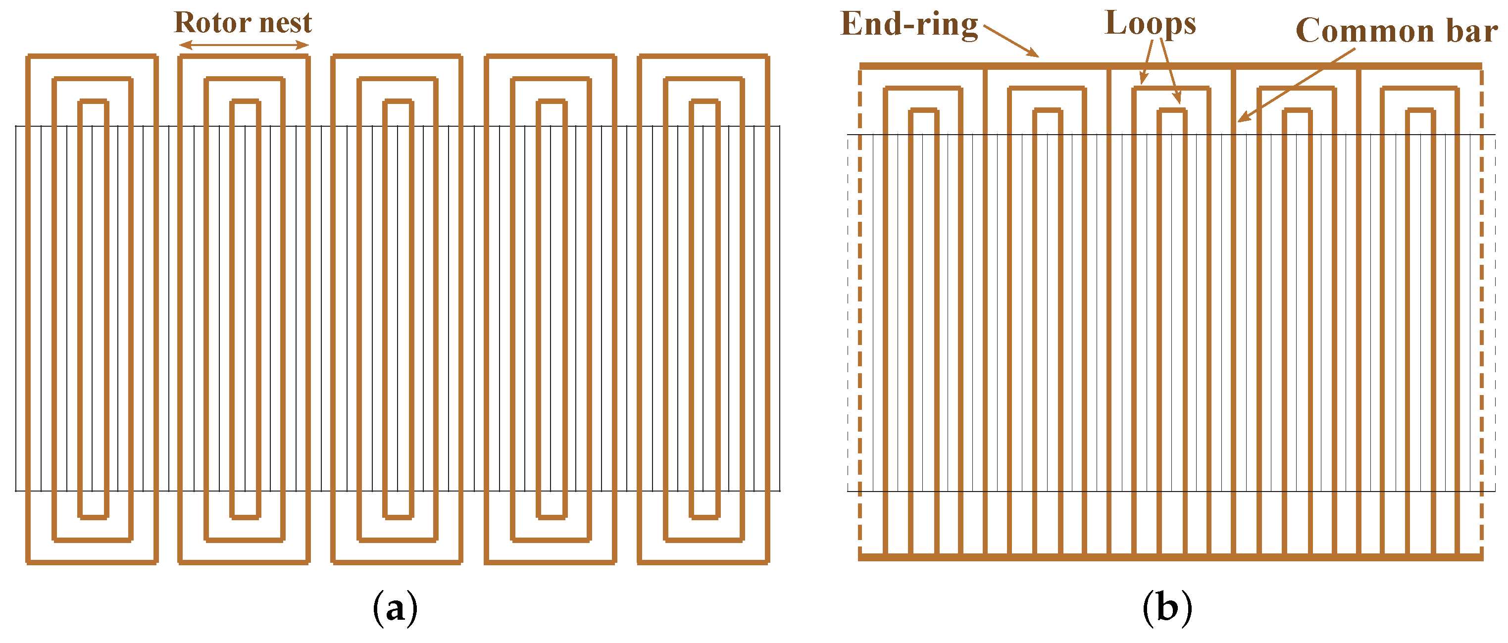
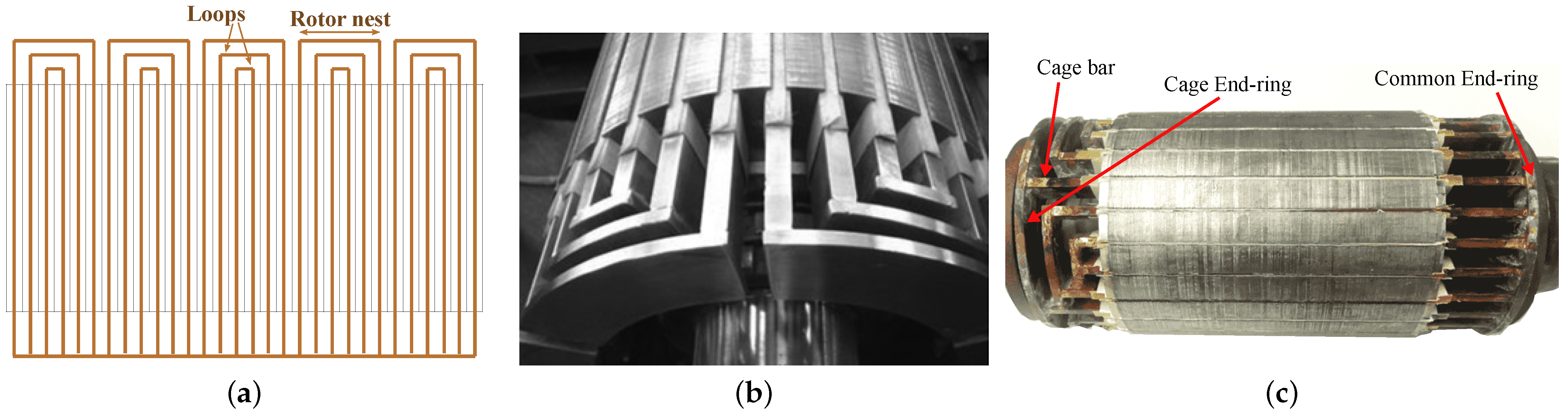
3.2. Rotor Winding Development

The nested loop (NL) and cage+NL rotors, whose origins are traced to [18], are currently deemed the most suitable for BDFMs [6,30,42]. The NL rotor winding arrangement and a prototype are shown in Figure 9a,b respectively. The cage+NL rotor winding arrangement has already being illustrated in Figure 5b, and a prototype is shown in Figure 9c. The winding arrangement in Figure 9a differs from that in Figure 5a by the presence of a common end ring, with the rotor illustrated in Figure 5a now sometimes called an isolated loop (IL) rotor [30]. These (NL, IL, & cage+NL) rotor types have robust builds with better torque performance and lower losses, compared to wound rotors [6].
A rotor similar to the NL rotor, but with double layers of bars, is highlighted in [30]. It is suggested that this double layer bar rotor has a larger torque envelope than the NL rotor; also higher efficiency due to less excess harmonic reactance. However, the increased complexity has manufacturing and control implications. The double layer bar rotor winding arrangement is illustrated in Figure 10a, while a prototype is shown in Figure 10b.
Whilst considering the high harmonic reactance and potential considerable skin effect in large BDFMs using NL rotors, series wound (SW) rotors are compared with NL rotors in [42]. The winding arrangement of the SW rotor is illustrated in Figure 11a, with a prototype shown in Figure 11b. Although the SW rotor has lower harmonic content and no skin effect issues, it has higher impedance and develops lower torque. Despite this, the performance of the SW rotor is deemed acceptable. It is also indicated that with similar slot fill factors, the SW and NL rotors will have similar torque performance due to identical referred rotor resistance. Also in [43], details of the design of a 60 kW BDFM with a special “double-sine” rotor are given. This rotor was designed as a potential BDFM rotor with greatly reduced harmonic content.
Although, the cage+NL rotor has similar advantages with the NL rotor, the NL configuration is more commonly used [6]. In [44,45], the NL and cage+NL rotors are compared based on their rotor equivalent circuit parameters, and it is suggested that the cage+NL rotors provide better performance due to their lower impedances. This advantage of cage+NL rotors is shown in [46] to be more evident when the disparity between p 1 and p 2 is greater. In cases where the p 1 value is close to p 2 , the NL rotor may perform better due to lower leakage inductance.
Initial guidelines for loop design of the NL and cage+NL rotors are given in [47]. It is suggested that loops with spans closer to the pitch of the higher pole number in the BDFM, are more efficient and effective in torque production. It is also suggested in [47], that loops with small spans have minor contributions to torque production, similar to suggestions in [44,48,49].
Observations in [44,47,48] indicate that the rotor loops should not necessarily be evenly spaced, and the width of the outer loops should be maximized. An increase in rotor loops per nest helps to mitigate space harmonics in BDFMs [27,48], and helps with better current distribution in BDFM rotors [27].

3.3. BDFM Sizing and Power Ratings

By analyzing the stator magnetic fields in BDFMs using a per phase equivalent circuit, a composite magnetic loading based on the stator fields is derived in [5]. Expressions for the BDFM power rating as a function of the pole pairs, stack length, airgap radius, electric and magnetic loadings, are given in [5]. The magnetic loading derivation in [5] was further modified in [27], as the loading derived in [5] was deemed too conservative, leading to over-sizing. Other aspects of the BDFM geometric sizing such as the slot teeth width and core height/depth are given in [27].
The BDFM power ratings expression in [5] is used to predict about a quarter reduction of the power rating in BDFMs, compared to conventional DFIGs of the same size. The influence of pole pair combinations on this disparity in power between BDFMs and DFIGs is investigated in [29]. It is suggested that combinations with lower ( p 1 / p 2 ) pole ratios have slight reduction in this disparity. These observations are somewhat echoed in [50], however, the analysed MW rated BDFMs have more than a quarter increase in mass when compared with DFIGs of similar power and operating speed. BDFMs also suffer a reduction in efficiency compared to DFIGs, as they have more windings, and consequently higher winding losses [6].
The impact of pole combination choices on the BDFM core depth is also characterized in [29]. For the pole pair combinations investigated in [29], it is observed that the BDFM core depths are at least two times bigger than DFIG core depths. However, it is also observed that as p 1 gets closer to p 2 , the core depth ratio between BDFMs and DFIGs of similar speeds gets smaller. Also, it is demonstrated in [51], how sections of an NL rotor core which do not contribute to the rotor magnetic circuit can be removed for weight reduction.
The effects of rotor leakage inductances on inverter ratings are illustrated in [25]. An increase in the rotor leakage inductance reduces the inverter ratings required for crowbar-less low voltage ride through (LVRT) requirements, but reduces the power factor management abilities. A trade-off between LVRT and power factor management requirements is therefore advocated in the choice and design of BDFM rotors. The use of magnetic wedges in optimizing inverter ratings is also discussed in [37,52]. However, it is worth noting that magnetic wedges are brittle and less reliable than non-magnetic wedges.

3.4. Vibrations and Harmonics Mitigation

In [53], it is affirmed that the combination of two magnetic fields of different poles in BDFMs produces extra vibrations not present in single field induction machines. It is further revealed that the bending forces on the stator back iron, which are significantly dependent on the pole pair combinations, contribute greatly to these vibrations. Apparently, combinations with pole numbers which are close, tend to produce higher vibrations. A method to mitigate these vibrations is also given, such that the machines are “stiffened” by increasing the stator core depth. This solution would have to be applied with caution, as BDFMs already have longer core depths compared to DFIGs [29].
In [54], it is stated that the most significant source of torque ripple in BDFMs is the winding distribution space harmonics; the excessive space harmonics present in the nested loop rotor structure being a major culprit. In [41,44,48], it is suggested that increasing the rotor loop spans helps in reducing harmonic content in BDFMs. Also, an increase in rotor loops per nest helps to mitigate space harmonics in BDFMs [27,48]. Using a coupled circuit (CC) model, the effect on torque ripple of NL and cage+NL rotor loop spans relative to the PW and CW pole pitches, is illustrated in [49]. It is shown how the CC model can be used to find suitable rotor designs for specific BDFM applications.
Slot types have effects on torque ripple [54]. Also, a double layer CW is expected to reduce torque ripple according to [55]. It is shown analytically in [56], that rotor skews help to reduce torque ripple. The effects of rotor skewing are further investigated in [57], and it is determined that skewing has little effects on losses, however, there is a slight reduction in the average torque.
As noted in Section 3.1, suitable pole pair combinations are investigated for torque ripple and harmonic content in [36,38,40]. Pole pair combinations that are multiples of the 2/3 combination have low harmonic content [6,36,38,40], however, the 2/3 combination itself suffers from UMP.

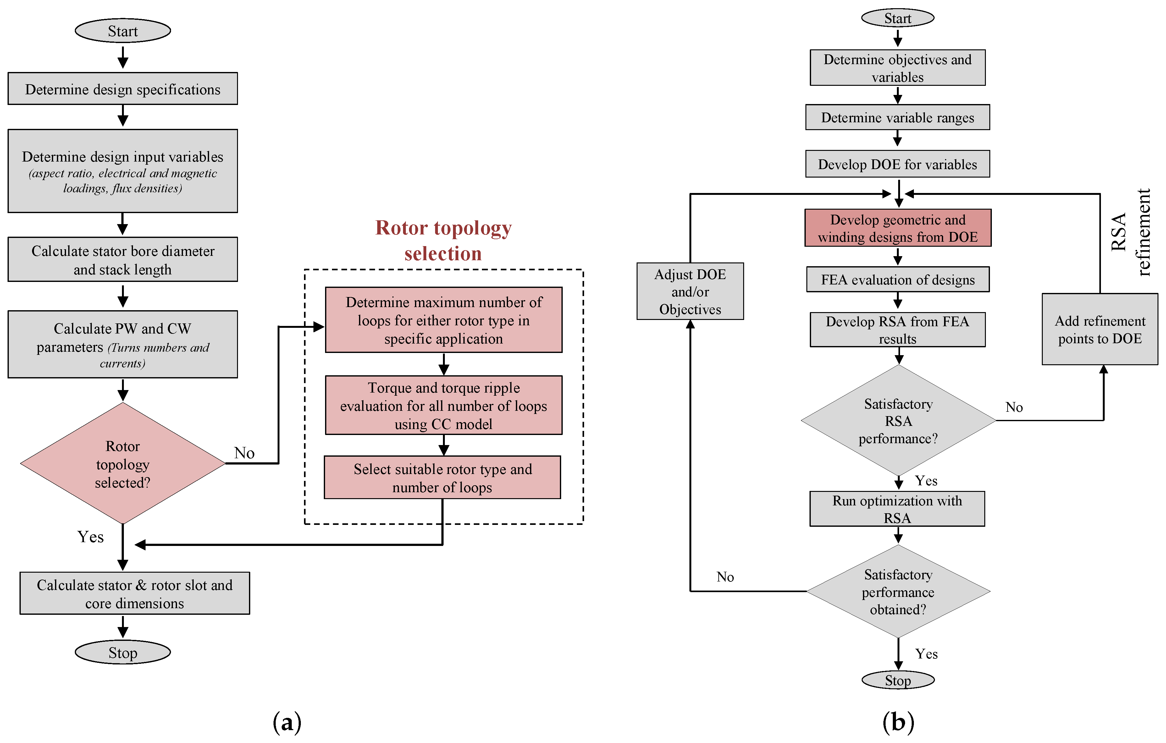
3.5. BDFM Design and Optimization Procedures

A proposed design procedure for a 6 MW BDFM is presented in [4], as illustrated in Figure 12. The power rating is selected because the largest DFIG generators used in wind turbines are rated similarly. In the design process, the BDFM equivalent circuit in [58] is used to obtain an initial design from the determined machine specifications. A coupled circuit (CC) BDFM model is then employed to evaluate the designed nested loop rotor. Finite element analysis (FEA) of the design is conducted to investigate the peak flux densities in the different iron parts, and obtain a close estimate of the magnetizing current. Thermal evaluation of the BDFM design is also recommended, alongside discussions with machine manufacturers, to aid practicality. System performances such as dynamics, control stability and LVRT capabilities are then considered in a fine-tuning of the design. This design procedure was reportedly employed for the 250 kW built and tested in [23].
Available BDFM electric equivalent circuit (EEC) models are limited in evaluating saturation, and FEA models are computationally costly. In light of these, a design approach for BDFMs using an EEC alongside a magnetic equivalent circuit (MEC) model is presented in [59]. The MEC developed in [60], is used to determine the flux distribution by the PW and CW, while the EEC model uses the MEC results to determine the machine performance.
It was noted in [61], that investigations on the design of BDFMs are limited in available literature. To that effect, a comprehensive BDFM design procedure considering the electromagnetic and thermal aspects of the BDFM, is presented in [61], with details of some of the models used given in [62]. A flowchart of the design procedure is given in Figure 13a. An EEC model is used to evaluate stator and rotor currents, while a static MEC as presented [62], is used to analyze the flux density distributions and core loss caused by these currents.
Temperature analysis is conducted in the design process in [61] using a lumped parameter thermal model illustrated in Figure 13b. The machine sections are designated as resistances, with the losses identified as heat sources. The description of the thermal model components are given in Table 2. A simple vibration analysis is also used to estimate vibrations in designs, and the optimization results are verified using 2-D FEA.
An optimization process using the imperialist competitive algorithm is used to maximize the power to weight ratio, efficiency, power factor, while minimizing the voltage regulation and rotor differential leakage inductance in [61]. Feasibility of different aspects of the BDFM design are monitored, such as the stator and rotor slots, the airgap length, shaft diameter etc. However, it is the CW power factor that was being maximized. The CW is also seemingly placed closest to the airgap.
An iterative (Tabu search) method is used to optimize the stator of a 180 frame size BDFM based on its per phase equivalent circuit model in [63]. The optimization was used to demonstrate how appropriate division of the stator slot area between the PW and CW, can enable BDFM operation at the magnetic and electric loading limits. This maximizes the power output, as was demonstrated by the 21 % increase in power from the original design. This method of optimization is also applied to a D160 frame BDFM in [64], to optimize the electric and magnetic loadings. The maximum motoring torque with a lower limit on the PW power factor of 0.75 is used for machine evaluation in the optimization process.
A magnetostatic FE BDFM model is presented in [39,65] to enable computationally efficient and accurate optimization processes. The non-dominated sorting genetic algorithm (NSGA-II) is used in [39] alongside the magnetostatic FE model to optimize the torque and efficiency of a BDFM designed for a D180 frame size. Geometric variables such as the stator inner radius and the ratios of slot/yoke height are used in the optimization process. The NSGA-II is also used in an optimization process in [40] to optimize the material cost and efficiency of a 3.2 MW BDFM. Similar geometric variables and magnetostatic FE models like in [39], are used in the optimization process in [40].
Both optimization processes in [39,40] are illustrated in Figure 14; A & B representing the optimized BDFM performances in [39,40] respectively. Different pole pair combinations ( p 1 / p 2 = 1/3, 2/3, 2/4 & 4/6) are tested in the optimization process in [39], with the 2/3 combination having the superior performance. However the 4/6 pole pair combination is used for the 3.2 MW BDFM in [40], because of the effects of the presence of UMP using the 2/3 combination. It is worth noting that the machines in [39,40] are optimized at the maximum torque operation points.
In [66], the authors of this paper presented a BDFM design process. A modified version of that process is presented here. The design process of a BDFM is represented with two intertwined processes; the geometric and winding design process illustrated in Figure 15a, and the power density optimization process illustrated in Figure 15b. The geometric process is used for each design iteration in the optimization process. Given the absence of specific values for the stack aspect ratio, electric and magnetic loadings in literature, practical values are identified during an optimization process, and these values are used in the final geometric and winding design of the BDFM.
In this design process, the CC model developed in [49] is used to determine the appropriate rotor type and structure (number of loops) for individual design applications. The optimization process which also employs the NSGA-II is used to maximize the efficiency and power density at power output constraints. It is demonstrated in [67], how the power output of BDFMs varies with PW power factor, such that the maximum generated power from a design may be much larger than the power generated at PW unity power factor. As a result, power output at PW unity power factor is used in the optimization process in [66]. A response surface approximation (RSA) developed from 2-D transient FEA results is used with the NSGA-II. The RSA is used to enable computational efficiency in the optimization process. A summary of the listed design and optimization procedures is given in Table 3.

4. Conclusions and Future Research

This review on the design of BDFMs can be divided into two parts; the evolution of cascade motors to BDFMs, and the recent developments in BDFM design. BDFMs have a rich history in terms of development, which has been laid out. The evolution was detailed in a way to provide the reader with perspective on BDFM development by highlighting pioneering designs and prototypes. Contemporary developments in the design of BDFMs are also described. These recent developments have revolved around the stator winding pole pair combinations, rotor topology and performance optimizations.
Recurring themes in recent BDFM design related articles include the selection of suitable pole pair combinations for the stator windings, vibrations & harmonic mitigation, and optimization of machine power density & efficiency. The stator structure design seems to be settled on the electrically isolated windings occupying different layers in the stator slots, with the PW typically closest to the airgap, and the CW closer to the core. However, there is no clear candidate for the pole pair combinations of these windings. Researchers are split between the 2/4 and 4/6 combinations for different reasons which are detailed. Thus, further insight on suitable pole pair combinations is crucial. The use of fractionally distributed windings for harmonics mitigation also needs to be further investigated.
On the other hand, a lot of research is still being conducted on the type and structure of BDFM rotors. Two rotor types, the NL and cage+NL rotors, are the leading choices of rotor types. The number of loops per nest for either rotor type is not fixed, and varies for reasons like harmonics, vibrations and torque performance. There is a possibility of significant skin effect in large BDFMs using NL or cage+NL rotors, and this needs to be investigated. Also, a comprehensive performance comparison between the NL, IL and cage+NL rotors is important.
BDFM sizing is detailed in available literature. However, the equations used for parameters like the airgap flux density or core depths are not definitive. To this effect, investigations across different power ratings may be required to identify the saturation tolerances of BDFMs. This will also help provide a more accurate basis for power density comparisons between BDFMs and DFIGs.
Different models have been used for design purposes, giving researchers interested in BDFM designs a variety of options. However, many require individual implementation, as they are unavailable in software form for public use, or in commercial software packages. This generally makes the design of BDFMs a longer process than conventional machines. Different design procedures have also been presented, and these provide useful insight into the design of BDFMs. Finally, it is reckoned that a robust design process for BDFMs would involve both machine and converter designs.

Author Contributions

Conceptualization, O.I.O. and N.G.; methodology, O.I.O. and N.G.; software, O.I.O.; validation, O.I.O.; formal analysis, O.I.O.; investigation, O.I.O.; resources, N.G.; data curation, O.I.O.; writing—original draft preparation, O.I.O.; writing—review and editing, O.I.O. and N.G.; visualization, O.I.O.; supervision, N.G.; project administration, N.G.; funding acquisition, N.G. All authors have read and agreed to the published version of the manuscript.

Funding

This research was funded by the Centre for Renewable and Sustainable Energy Studies (CRSES), at Stellenbosch University, South Africa, and the Department of Science and Innovation (DSI) in South Africa.

Conflicts of Interest

The authors declare no conflict of interest.

Abbreviations

The following abbreviations are used in this manuscript:
BDFMBrushless doubly fed machine
CCCoupled circuit
CWControl winding
DFIGDoubly fed induction generator
EECElectric equivalent circuit
FEAFinite element analysis
ILIsolated loops
IMInduction machine
LVRTLow voltage ride through
MECMagnetic equivalent circuit
NLNested loops
NSGA-IINon dominated sorting genetic algorithm
O&MOperational and maintenance
p 1 PW pole pairs
p 2 CW pole pairs
PWPower winding
RSAResponse surface approximation
SCIMSquirrel cage induction motor
SWSeries wound
UMPUnbalanced magnetic pull

References

  1. Polinder, H.; Ferreira, J.A.; Jensen, B.B.; Abrahamsen, A.B.; Atallah, K.; McMahon, R.A. Trends in Wind Turbine Generator Systems. IEEE J. Emerg. Sel. Top. Power Electron. 2013, 1, 174–185. [Google Scholar] [CrossRef]
  2. Carroll, J.; McDonald, A.; Dinwoodie, I.; McMillan, D.; Revie, M.; Lazakis, I. Availability, operation and maintenance costs of offshore wind turbines with different drive train configurations. Wind Energy 2017, 20, 361–378. [Google Scholar] [CrossRef] [Green Version]
  3. Global Wind Energy Council (GWEC). Global Wind Report 2021; Technical Report; GWEC: Brussels, Belgium, 2021. [Google Scholar]
  4. Abdi, E.; Tatlow, M.R.; McMahon, R.A.; Tavner, P. Design and performance analysis of a 6 MW medium-speed Brushless DFIG. In Proceedings of the 2nd IET Renewable Power Generation Conference (RPG 2013), Beijing, China, 9–11 September 2013; pp. 1–4. [Google Scholar] [CrossRef] [Green Version]
  5. McMahon, R.A.; Roberts, P.C.; Wang, X.; Tavner, P.J. Performance of BDFM as generator and motor. IEE Proc. Electr. Power Appl. 2006, 153, 289–299. [Google Scholar] [CrossRef] [Green Version]
  6. Strous, T.D.; Polinder, H.; Ferreira, J.A. Brushless doubly-fed induction machines for wind turbines: Developments and research challenges. IET Electr. Power Appl. 2017, 11, 991–1000. [Google Scholar] [CrossRef]
  7. Zhang, F.; Yu, S.; Wang, H.; Wang, Y.; Wang, D. Overview of research and development status of brushless doubly-fed machine system. Chin. J. Electr. Eng. 2016, 2, 1–13. [Google Scholar] [CrossRef]
  8. Han, P.; Cheng, M.; Ademi, S.; Jovanovic, M.G. Brushless doubly-fed machines: Opportunities and challenges. Chin. J. Electr. Eng. 2018, 4, 1–17. [Google Scholar] [CrossRef]
  9. Bell, L. Some Facts about Polyphase Motors. Trans. Am. Inst. Electr. Eng. 1894, 11, 559–569. [Google Scholar] [CrossRef]
  10. Hunt, L.J. The “cascade” induction motor. J. Inst. Electr. Eng. 1914, 52, 406–426. [Google Scholar] [CrossRef]
  11. Adams, A.D. Motor Speed Regulation. Trans. Am. Inst. Electr. Eng. 1899, 16, 443–445. [Google Scholar] [CrossRef]
  12. Scott, C.F. Variable Speed Motor Control. Trans. Am. Inst. Electr. Eng. 1902, 20, 111–114. [Google Scholar] [CrossRef]
  13. Siemens Brothers & Co. Ltd.; Lydall, F. Improvements in Polyphase Induction Motors. British Patent 16839, 23 July 1903. [Google Scholar]
  14. Hunt, L.J. A new type of induction motor. Electr. Eng. J. Inst. 1907, 39, 648–667. [Google Scholar] [CrossRef]
  15. Leonard, H.W. Volts vs. Ohms; Speed Regulation of Electric Motors. Trans. Am. Inst. Electr. Eng. 1896, 13, 373–386. [Google Scholar] [CrossRef] [Green Version]
  16. Steinmetz, C.P. Operating alternating motors. U.S. Patent 587340 A, 3 August 1897. [Google Scholar]
  17. Creedy, F. Some developments in multi-speed cascade induction motors. Electr. Eng. J. Inst. 1921, 59, 511–532. [Google Scholar] [CrossRef]
  18. Broadway, A.R.W.; Burbridge, L. Self-cascaded machine: A low-speed motor or high-frequency brushless alternator. Electr. Eng. Proc. Inst. 1970, 117, 1277–1290. [Google Scholar] [CrossRef]
  19. Smith, B.H. Theory and Performance of a Twin Stator Induction Machine. IEEE Trans. Power Appar. Syst. 1966, PAS-85, 123–131. [Google Scholar] [CrossRef]
  20. Smith, B.H. Synchronous Behavior of Doubly Fed Twin Stator Induction Machine. IEEE Trans. Power Appar. Syst. 1967, PAS-86, 1227–1236. [Google Scholar] [CrossRef]
  21. Wallace, A.K.; Spee, R.; Lauw, H.K. Dynamic modeling of brushless doubly-fed machines. In Proceedings of the Conference Record of the IEEE Industry Applications Society Annual Meeting, San Diego, CA, USA, 1–5 October 1989; pp. 329–334. [Google Scholar] [CrossRef]
  22. Brune, C.S.; Spee, R.; Wallace, A.K. Experimental evaluation of a variable-speed, doubly-fed wind-power generation system. IEEE Trans. Ind. Appl. 1994, 30, 648–655. [Google Scholar] [CrossRef]
  23. Abdi, E.; Mcmahon, R.; Malliband, P.; Shao, S.; Mathekga, M.E.; Tavner, P.; Abdi, S.; Oraee, A.; Long, T.; Tatlow, M. Performance analysis and testing of a 250 kW medium-speed brushless doubly-fed induction generator. IET Renew. Power Gener. 2013, 7, 631–638. [Google Scholar] [CrossRef]
  24. Rochelle, P.; Spee, R.; Wallace, A.K. The effect of stator winding configuration on the performance of brushless doubly-fed machines in adjustable speed drives. In Proceedings of the Conference Record of the 1990 IEEE Industry Applications Society Annual Meeting, Seattle, WA, USA, 7–12 October 1990; pp. 331–337. [Google Scholar] [CrossRef]
  25. Oraee, A.; Abdi, E.; McMahon, R.A. Converter rating optimisation for a brushless doubly fed induction generator. IET Renew. Power Gener. 2015, 9, 360–367. [Google Scholar] [CrossRef]
  26. McMahon, R.A.; Abdi, E.; Malliband, P.D.; Shao, S.; Mathekga, M.E.; Tavner, P.J. Design and testing of a 250 kW medium-speed Brushless DFIG. In Proceedings of the 6th IET International Conference on Power Electronics, Machines and Drives (PEMD 2012), Bristol, UK, 27–29 March 2012; pp. 1–6. [Google Scholar] [CrossRef]
  27. McMahon, R.A.; Mathekga, M.E.; Wang, X.; Tatlow, M.R. Design considerations for the brushless doubly-fed (induction) machine. IET Electr. Power Appl. 2016, 10, 394–402. [Google Scholar] [CrossRef] [Green Version]
  28. Rüncos, F.; Carlson, R.; Sadowski, N.; Kuo-Peng, P. Performance analysis of a doubly fed twin stator cage induction generator. In Recent Developments of Electrical Drives; Springer: Dordrecht, The Netherlands, 2006; pp. 361–373. [Google Scholar]
  29. Oraee, A.; McMahon, R.; Abdi, E.; Abdi, S.; Ademi, S. Influence of Pole-pair Combinations on the Characteristics of the Brushless Doubly Fed Induction Generator. IEEE Trans. Energy Convers. 2020, 35, 1151–1159. [Google Scholar] [CrossRef]
  30. Roberts, P.C. A Study of Brushless Doubly-Fed (Induction) Machines. Ph.D. Thesis, University of Cambridge, Cambridge, UK, 2004. [Google Scholar]
  31. Roberts, P.C.; Long, T.; Mcmahon, R.A.; Shao, S.; Abdi, E.; Maciejowski, J.M. Dynamic modelling of the brushless doubly fed machine. IET Electr. Power Appl. 2013, 7, 544–556. [Google Scholar] [CrossRef]
  32. Kusko, A.; Somuah, C.B. Speed Control of a Single-Frame Cascade Induction Motor with Slip-Power Pump Back. IEEE Trans. Ind. Appl. 1978, IA-14, 97–105. [Google Scholar] [CrossRef]
  33. Gorginpour, H.; Oraee, H.; Abdi, E. Calculation of Core and Stray Load Losses in Brushless Doubly Fed Induction Generators. IEEE Trans. Ind. Electron. 2014, 61, 3167–3177. [Google Scholar] [CrossRef]
  34. Chapman, F. The production of noise and vibration by certain squirrel-cage induction motors. J. Inst. Electr. Eng. 1922, 61, 39–48. [Google Scholar] [CrossRef] [Green Version]
  35. Abdi, S.; Abdi, E.; McMahon, R. A Study of Unbalanced Magnetic Pull in Brushless Doubly Fed Machines. IEEE Trans. Energy Convers. 2015, 30, 1218–1227. [Google Scholar] [CrossRef]
  36. Van der Blij, N.H.; Strous, T.D.; Wang, X.; Polinder, H. A novel analytical approach and finite element modelling of a BDFIM. In Proceedings of the 2014 International Conference on Electrical Machines (ICEM), Berlin, Germany, 2–5 September 2014; pp. 346–352. [Google Scholar] [CrossRef]
  37. Abdi, E.; Oraee, A.; Abdi, S.; McMahon, R.A. Design of the Brushless DFIG for optimal inverter rating. In Proceedings of the 7th IET International Conference on Power Electronics, Machines and Drives (PEMD 2014), Manchester, UK, 8–10 April 2014; pp. 1–6. [Google Scholar] [CrossRef]
  38. Strous, T.D.; Wang, X.; Polinder, H.; Ferreira, J.A.B. Finite element based multi-objective optimization of a brushless Doubly-Fed Induction Machine. In Proceedings of the 2015 IEEE International Electric Machines Drives Conference (IEMDC), Coeur d’Alene, ID, USA, 10–13 May 2015; pp. 1689–1694. [Google Scholar] [CrossRef]
  39. Wang, X.; Strous, T.D.; Lahaye, D.; Polinder, H.; Ferreira, J.A. Modeling and Optimization of Brushless Doubly-Fed Induction Machines Using Computationally Efficient Finite-Element Analysis. IEEE Trans. Ind. Appl. 2016, 52, 4525–4534. [Google Scholar] [CrossRef]
  40. Wang, X.; Polinder, H.; Lahaye, D.; Ferreira, J.A. FE based multi-objective optimization of a 3.2 MW brushless doubly-fed induction machine. In Proceedings of the 2017 IEEE Workshop on Electrical Machines Design, Control and Diagnosis (WEMDCD), Nottingham, UK, 20–21 April 2017; pp. 89–94. [Google Scholar] [CrossRef]
  41. Strous, T.D.; Wang, X.; Polinder, H.; Ferreira, J.A. Evaluating Harmonic Distortions in Brushless Doubly Fed Induction Machines. IEEE Trans. Magn. 2017, 53, 1–10. [Google Scholar] [CrossRef]
  42. Mcmahon, R.; Tavner, P.; Abdi, E.; Malliband, P.; Barker, D. Characterising brushless doubly fed machine rotors. IET Electr. Power Appl. 2013, 7, 535–543. [Google Scholar] [CrossRef]
  43. Xiong, F.; Wang, X. Design of a Low-Harmonic-Content Wound Rotor for the Brushless Doubly Fed Generator. IEEE Trans. Energy Convers. 2014, 29, 158–168. [Google Scholar] [CrossRef]
  44. Logan, T.G.; McMahon, R.A.; Tavner, P.J.; Tohidi, S. A comparison of cage and nested-loop BDFM rotors. In Proceedings of the 6th IET International Conference on Power Electronics, Machines and Drives (PEMD 2012), Bristol, UK, 27–29 March 2012; pp. 1–6. [Google Scholar] [CrossRef]
  45. Abdi, S.; Grace, A.; Abdi, E.; McMahon, R. A new optimized rotor design for brushless doubly fed machines. In Proceedings of the 20th International Conference on Electrical Machines and Systems (ICEMS), Sydney, NSW, Australia, 11–14 August 2017; pp. 1–6. [Google Scholar] [CrossRef] [Green Version]
  46. Oraee, A.; Abdi, E.; Abdi, S.; McMahon, R.; Tavner, P.J. Effects of Rotor Winding Structure on the BDFM Equivalent Circuit Parameters. IEEE Trans. Energy Convers. 2015, 30, 1660–1669. [Google Scholar] [CrossRef]
  47. Wallace, A.; Rochelle, P.; Spee, R. Rotor modeling and development for brushless doubly-fed machines. Electr. Mach. Power Syst. 1995, 23, 703–715. [Google Scholar] [CrossRef]
  48. Wang, X.; Liu, D.; Polinder, H.; Lahaye, D.; Ferreira, J.A. Comparison of nested-loop rotors in brushless doubly-fed induction machines. In Proceedings of the 19th International Conference on Electrical Machines and Systems (ICEMS), Chiba, Japan, 13–16 November 2016; pp. 1–6. [Google Scholar]
  49. Olubamiwa, O.I.; Gule, N.; Kamper, M.J. Coupled circuit analysis of the brushless doubly fed machine using the winding function theory. IET Electr. Power Appl. 2020, 14, 1558–1569. [Google Scholar] [CrossRef]
  50. Strous, T.D.; Shipurkar, U.; Polinder, H.; Ferreira, J.A. Comparing the Brushless DFIM to other Generator Systems for Wind Turbine Drive-Trains. J. Phys. Conf. Ser. 2016, 753, 112014. [Google Scholar] [CrossRef]
  51. Abdi, S.; Abdi, E.; Oraee, A.; McMahon, R. Optimization of Magnetic Circuit for Brushless Doubly Fed Machines. IEEE Trans. Energy Convers. 2015, 30, 1611–1620. [Google Scholar] [CrossRef]
  52. Abdi, S.; Abdi, E.; Oraee, A.; McMahon, R.A. Investigation of magnetic wedge effects in large-scale BDFMs. In Proceedings of the 2nd IET Renewable Power Generation Conference (RPG 2013), Beijing, China, 9–11 September 2013; pp. 1–4. [Google Scholar] [CrossRef] [Green Version]
  53. Logan, T.; Mcmahon, R.; Seffen, K. Noise and vibration in brushless doubly fed machine and brushless doubly fed reluctance machine. IET Electr. Power Appl. 2014, 8, 50–59. [Google Scholar] [CrossRef]
  54. Strous, T.D.; Wang, X.; Polinder, H.; Ferreira, J.A.B. Brushless doubly-fed induction machines: Torque ripple. In Proceedings of the 2015 IEEE International Electric Machines Drives Conference (IEMDC), Coeur d’Alene, ID, USA, 10–13 May 2015; pp. 1145–1151. [Google Scholar] [CrossRef]
  55. Chen, J.; Zhang, W. Harmonics in Brushless Doubly Fed Induction Generator for Torque Ripple Analysis and Modeling. IEEE Trans. Magn. 2014, 50, 1–4. [Google Scholar] [CrossRef]
  56. Gorginpour, H.; Jandaghi, B.; Oraee, A.; Saket, M.A.; Ahmadian, M.; Oraee, H. Reduction of the torque ripple in Brushless Doubly-Fed Machine. In Proceedings of the 2011 3rd International Youth Conference on Energetics (IYCE), Leiria, Portugal, 7–9 July 2011; pp. 1–7. [Google Scholar]
  57. Wang, X.; Strous, T.D.; Lahaye, D.; Polinder, H.; Ferreira, J.A. Effects of rotor skew on the performance of brushless doubly-fed induction machine. In Proceedings of the 2015 IEEE International Electric Machines Drives Conference (IEMDC), Coeur d’Alene, ID, USA, 10–13 May 2015; pp. 260–265. [Google Scholar] [CrossRef]
  58. Roberts, P.C.; McMahon, R.A.; Tavner, P.J.; Maciejowski, J.M.; Flack, T.J. Equivalent circuit for the brushless doubly fed machine (BDFM) including parameter estimation and experimental verification. IEE Proc. Electr. Power Appl. 2005, 152, 933–942. [Google Scholar] [CrossRef] [Green Version]
  59. Chang, Y.H.; Li, Y.T.; Lin, I.H.; Hsieh, M.F. A design approach integrating the magnetic circuit and electric circuit models for BDFIM. In Proceedings of the 2014 17th International Conference on Electrical Machines and Systems (ICEMS), Hangzhou, China, 22–25 October 2014; pp. 1685–1690. [Google Scholar] [CrossRef]
  60. Hsieh, M.F.; Lin, I.H.; Hsu, Y.C.; McMahon, R.A. Design of Brushless Doubly-Fed Machines Based on Magnetic Circuit Modeling. IEEE Trans. Magn. 2012, 48, 3017–3020. [Google Scholar] [CrossRef]
  61. Gorginpour, H.; Oraee, H.; McMahon, R.A. Electromagnetic-Thermal Design Optimization of the Brushless Doubly Fed Induction Generator. IEEE Trans. Ind. Electron. 2014, 61, 1710–1721. [Google Scholar] [CrossRef]
  62. Gorginpour, H.; Oraee, H.; McMahon, R.A. A Novel Modeling Approach for Design Studies of Brushless Doubly Fed Induction Generator Based on Magnetic Equivalent Circuit. IEEE Trans. Energy Convers. 2013, 28, 902–912. [Google Scholar] [CrossRef]
  63. Wang, X.; Roberts, P.C.; McMahon, R.A. Optimisation of BDFM stator design using an equivalent circuit model and a search method. In Proceedings of the 3rd IET International Conference on Power Electronics, Machines and Drives (PEMD 2006), Dublin, Ireland, 4–6 April 2006; pp. 606–610. [Google Scholar] [CrossRef] [Green Version]
  64. Wang, X.; McMahon, R.A.; Tavner, P.J. Design of the Brushless Doubly-Fed (Induction) Machine. In Proceedings of the 2007 IEEE International Electric Machines Drives Conference, Antalya, Turkey, 3–5 May 2007; pp. 1508–1513. [Google Scholar] [CrossRef]
  65. Wang, X.; Strous, T.D.; Lahaye, D.; Polinder, H.; Ferreira, J.A. Finite element modeling of brushless doubly-fed induction machine based on magneto-static simulation. In Proceedings of the 2015 IEEE International Electric Machines Drives Conference (IEMDC), Coeur d’Alene, ID, USA, 10–13 May 2015; pp. 315–321. [Google Scholar] [CrossRef]
  66. Olubamiwa, O.I.; Gule, N. Design and optimization of a Cage + Nested loops rotor BDFM. In Proceedings of the 2020 International Conference on Electrical Machines (ICEM), Gothenburg, Sweden, 23–26 August 2020; pp. 1868–1874. [Google Scholar] [CrossRef]
  67. Olubamiwa, O.I.; Gule, N. Prioritizing power factor in power density assessments of doubly fed induction generator alternatives. In Proceedings of the 2020 International Symposium on Power Electronics, Electrical Drives, Automation and Motion (SPEEDAM), Sorrento, Italy, 24–26 June 2020; pp. 47–52. [Google Scholar]
Figure 1. Steinmetz cascade system examples: (a) two motors with rotor of primary motor connected to secondary stator, (b) two motors with both rotors connected to each other, and (c) four motors [16].
Energies 15 00725 g001
Figure 2. Thompson motor winding illustration [14].
Energies 15 00725 g002
Figure 3. Schematic representation of the Lydall motor [13].
Energies 15 00725 g003
Figure 4. Hunt motor stator connections: (a) 4 poles, (b) 8 poles, and (c) (4 + 8) poles [10].
Energies 15 00725 g004
Figure 5. Broadway & Burbridge rotor winding arrangements: (a) Graded winding rotor and (b) multicircuit winding rotor [18].
Energies 15 00725 g005
Figure 6. Broadway & Burbridge rotor prototypes: (a) Graded winding rotor for (6 + 2) poles machine, and (b) multicircuit rotor for (18 + 12) poles machine [18].
Energies 15 00725 g006
Figure 7. Stator winding arrangement of a BDFM with p 1 / p 2 = 2 / 3 .
Energies 15 00725 g007
Figure 8. Force diagram for p 1 / p 2 = 2 / 3 (adapted from [34]).
Energies 15 00725 g008
Figure 9. Widely used BDFM rotors: (a) NL rotor winding arrangement for p 1 + p 2 = 5 , (b) NL rotor prototype [42], and (c) Cage + NL rotor prototype.
Energies 15 00725 g009
Figure 10. Double layer bar rotor: (a) Winding arrangement for p 1 / p 2 = 2 / 4 , and (b) prototype [30].
Energies 15 00725 g010
Figure 11. SW rotor: (a) Winding arrangement for p 1 + p 2 = 5 , and (b) prototype [42].
Energies 15 00725 g011
Figure 12. Proposed design procedure for a 6-MW BDFM [4].
Energies 15 00725 g012
Figure 13. Design process and thermal model in [61]: (a) Design flow chart, and (b) Radial equivalent thermal network of a BDFM.
Energies 15 00725 g013
Figure 14. NSGA-II optimizations flow chart. Optimization processes in [39,40].
Energies 15 00725 g014
Figure 15. Design process proposed by authors: (a) Geometric and winding design process and (b) optimization process.
Energies 15 00725 g015
Table 1. Relative performance of popular BDFM pole pair combinations.
ParametersPole Pair Combinations ( p 1 / p 2 )
2/32/44/6
Power density [29,38,39]HighMediumLow
Efficiency [29,38,39]HighMediumLow
Torque ripple [38]LowHighLow
Harmonic distortion [40,41]LowHighLow
UMP [35,36]Present--
Table 2. Resistance descriptions in thermal model [61].
ComponentDescription
Rs0Thermal resistance between external frame and
environment with thermal resistance of external frame
Rs1Thermal resistance of stator core
Rs2Thermal resistance of coil insulator
Rs3/Rs5
Rs7/Rs9
Thermal resistance of PW & CW end-winding to
middle of slot at drive end/non-drive end sections
Rs4/Rs6
Rs8/Rs10
Thermal resistance between PW & CW end-winding and
environment at drive end/non-drive end sections
RagThermal resistance between rotor and stator
Rr1Thermal resistance of rotor slot insulator
Rr2/Rr4Thermal resistance of rotor end-winding to
middle of slot at drive end/non-drive end sections
Rr3/Rr5Thermal resistance between rotor end-winding and
environment at drive end/non-drive end sections
Rr6Thermal resistance of rotor core
Rr7Thermal resistance between shaft and environment
Pfe,(s/r), PfricStator/rotor iron, frictional losses
Pcu,ew, Pcu,slotEnd-winding, slot copper losses
Table 3. Summary of design and optimization procedures.
DescriptionRelevant ReferencesModels/Analytical MethodsApplications/AdvantagesLimitations
6 MW BDFM design[4,23,58]Equivalent circuit models, CC models, FEAComprehensive MW rated BDFM designImpractical for smaller designs
BDFM design with EEC and MEC models[59,60]EEC and MEC modelsComputationally cheapLimited functionality
Electromagnetic and thermal design of BDFMs[61,62]EEC, MEC & thermal models, vibration analysis, 2D FEA, imperialist competitive algorithmRobust design procedure; broad functionalityComplex implementation
BDFM rotor design and power density optimization[49,66,67]CC model, Transient FEA, NSGA-II, Response surface approximationsRotor type selection; Systematic power output evaluation; computationally cheap optimizationNo thermal considerations; slightly complex implementation
Electric and magnetic loading optimization[63,64]Equivalent circuit model, Tabu search methodMaximizing power output, easy implementationPower factor constraint too low
Multi-objective optimizations[39,40,65]Magnetostatic FEA, NSGA-IIComputationally cheap optimizations; material cost, efficiency & torque optimizationsNo power factor consideration
Publisher’s Note: MDPI stays neutral with regard to jurisdictional claims in published maps and institutional affiliations.

