1. Introduction
Renewable energy systems are now being installed near newly built domestic or industrial installations due to their main advantage of providing an additional environmentally friendly source of energy. This is particularly important in extensive rural power systems and conventional source-based autonomous microgrids, where the power supply reliability is generally lower. In this context, renewable energy systems are often upgraded with energy storage systems to improve the stability of their operation and simultaneously complemented with cogeneration systems utilizing natural gas. The cogeneration systems can be divided into high and medium power systems and micro installations, according to the power generated. Currently in Poland, power generation systems based on micro-cogeneration (below 50 kW) represent a minor fraction of existing cogeneration systems. According to the data presented in [
1], which shows cogeneration capacity in Poland, and [
2], which presents heating plant modernization projects with support for renewable energy and cogeneration technologies, high and medium power cogeneration systems are mainly used in Poland.
The use of micro-cogeneration installations is small and their implementation is particularly notable in rural areas or on the edges of urban agglomerations, due to the fact that the construction of a power transmission grid is not economically viable. The main users of micro-cogeneration installations include small enterprises, schools, small towns, and villages, where joint production of thermal and electrical energy is particularly justified. In that case, it is possible to obtain both electricity and heat with a cogeneration system as the primary power source, covering the local energy demand with a minimal share of the main power grid in case of need [
3]. On the other hand, during hot days with relatively high temperatures, these installations can be used to provide power for air conditioning systems operating with absorption chillers. Selecting an energy source for a microgeneration system based on system location is essential to ensuring the efficiency and reliability of the energy supply [
4]. The types of energy sources used in micro-cogeneration systems can be classified as follows [
5]:
liquid fuels (petrol, diesel, ethanol, bio fuels),
gas fuels (natural gas, biogas),
solid fuels (coal, biomass),
energy derived from solar and wind energy.
Selecting an energy source is a key factor in the economics of microgeneration system installation [
5]. An additional aspect is adequate selection of renewable energy sources used to support the electrical power generation. This is usually done taking into account local geographical conditions. For locations outside the city, where area constraints for the use of the RES are not a key issue, the cooperation of different renewable energy sources is considered. Their optimization is discussed, among others, in report [
6], which presents wind power integration optimization; in [
7], an idea for optimal planning of the energy production is shown, and in [
8], optimization issues of local cogeneration stations are discussed. Microgeneration systems are, as a rule, equipped with various energy storage systems to support their integration into the local electrical grid.
The paper presents the analysis of the design and implementation of a hybrid power generation system connected to the available rural power system used to supply a low power industrial plant. The hybrid system is composed of a co-generation system, renewable energy sources, and a storage system with a battery and a supercapacitor making use of power electronic interfaces. The application of the storage system becomes necessary after assuming energy generation from wind and solar energy sources to provide local power at the required level resulting from the scheduled power demand of the power plant. The aim of the hybrid microgeneration control system is to ensure control of energy flow during windless and/or sunless periods of the day. On the other hand, it also must ensure energy storage capability during periods when the generated power exceeds the demand or consumption. This solution is widely used in low-power installations, as reported in [
9,
10]. Optimization of hybrid microgeneration systems has been presented in [
11], where the development of an energy management system was required to provide power adjusted to local power demand, but also to monitor and switch the operation mode for the assumed different scenarios of operating conditions and power generation schedules.
This paper deals mainly with the analysis of an energy management system (EMS) implemented in a low-power industrial plant. The EMS, developed as part of work supported by a target project, can be used in household systems, small enterprises, public buildings, or farms. The paper presents selected measurement results obtained between 2012 and 2016. The idea of the implemented energy management system is to enable real-time measurements in the installed microgeneration system and thus to ensure flexible control of power generation and its adjustment to current demand and consumption, which results from the actual state of the rural power system, variable load and weather conditions, and fault management algorithms on the site, as well as from the scheme of operation adopted to deal with the predicted scenarios. Moreover, the energy control system ensures control of cooperation between different energy sources and energy conversion in renewable energy systems, as well as control of storage systems, power converter-based power conversion systems, load changes, and the quality of the power delivered by the available rural power system.
2. Developed Microgrid System and Applied Physical Model of Energy Management System
The demonstrated system was implemented at the company Infracorr Ltd. [
12] located in Niestępowo in Poland. The micro-energy generation system was constructed and started operation in the beginning of 2012. It was implemented to provide electrical power to a low-power plant with maximal global electrical and thermal power demands of 30 kW and 20 kW, respectively, as shown in
Figure 1. The rated power estimated on the basis of available data was set at 30 kW; however, the generated power never exceeded 20 kW. The verification of the data declared by the manufacturers of system components compared with the adopted preliminary assumptions showed that the real performance of two main system components: the cogeneration system and the wind turbine, differs significantly from the declared nominal power values. For the cogeneration system, for which the electrical power capacity was initially declared by the manufacturer at 15 kW, verification showed the maximum power at 11 kW. According to the adopted assumptions, the expected wind turbine performance was to obtain a measured active power of 12 kW at the estimated average wind speed of 12 m/s. The measurement results obtained from the performed tests confirmed that the wind turbine can only reach a maximum power of 8 kW. These measurements were used as a basis for the analysis of the existing microgrid implementation and for further improvement of the project. The studied power generation system comprises a number of components that cooperate together to meet the company demand for electrical and thermal energy. These components, shown in
Figure 1, are listed as follows:
a combined heat and power cogeneration system (TOTEM), composed of ten elements. It is powered by natural gas and rated to produce 10 kW of electric power and 20 kW of thermal power. Detailed specifications are reported in [
13];
a 3-bladed horizontal-axis wind turbine E12, manufactured by Eniwa with a rotor diameter of 5.98 m and hub height of 18 m. The turbine is designed to operate within wind speeds ranging from 3.5 m/s to a maximum of 20 m/s, with rated power of 12 kW and 40 dB noise emission at the sound source point;
a PV array with 12 PV Mitsubishi Electric (PV-TD185 MF5) solar panels. Its total rated power is 2.2 kW. Detailed parameters are reported in [
14].
The electrical energy storage system is composed of:
fourteen 12 V 65 Ah batteries for a single unit [
15]. This power source can be used for a relatively long period to support the microgrid;
72 prismatic LS Mtron Ltd. supercapacitors, with total capacitance of 42 F. Each unit (type LSUC 002R7C 3000F EA [
16]), has a capacity of 3000 F and represents a power source that can be used for a short transient period to provide high power density;
Two MMB–Drives Ltd. power converters [
17] are used to ensure bidirectional power conversion. They support two different tasks:
- ○
power conversion between the cogeneration system, the wind turbine generator, and the storage system. For this task, the MMB018 module is used;
- ○
power conversion between the PV system and the storage system. For this task, the MMB015 module is used.
Three energy management system modules are applied to ensure the microgrid power management and its integration with the rural power grid. The energy management system modules used in this project were designed by EMS Ltd. [
18].
The energy management system modules implemented in the microgrid operate as independent functional program blocks. Each block is configured individually according to the desired functionalities and provides:
measurement of electrical parameters;
control of digital and analogue inputs and outputs;
data acquisition, processing, and analysis;
internal communication between control modules in the microgrid.
The implemented microgrid control system is designed to operate according to scheduled scenarios, aiming to minimize the operation cost in on-grid or off-grid operation modes.
If the level of power demanded by the company exceeds the available power of the microgrid, the control system can disconnect less significant loads or control the reactive power drawn from the rural power system or fed to the grid from the microgrid, in order to comply with the restrictions of the reactive power flow specified in the distribution network operation guidelines by the distribution network operator avoid serious financial penalty. The distribution network operator manages a network of up to 110 kV, while the transmission network operator PSE S.A. manages power networks of 110 kV–220 kV, 400 kV, and 800 kV.
In the basic operation mode, the microgrid control system cooperates with the data analysis module, having implemented energy quality analysis sheets for the energy supplied from or returned to the network in accordance with local (Polish) requirements [
19]. The EMS system also allows the determination of the following basic quantities describing power system operation:
active and reactive energy (capacitive or inductive);
power coefficient for active, reactive, and apparent power;
amplitudes of harmonic components of voltage and current, up to 40 harmonics;
total harmonic distortions (THDs) of current and voltage, up to 40 harmonics;
activation of the islanding operation mode;
energy management control variables in islanding mode operation.
Moreover the control system provides diagnostic functionalities in accordance with the requirements of the standard, including detection and identification of abnormal network operating conditions such as [
20]:
Additionally, the EMS monitors the operation status of its own modules, registering identified abnormal states in the internal memory (4 GB) for up to 7 days of system operation. In the next step, it automatically transfers the registered data to an external server via an Ethernet network. The internal communication module is equipped with two serial ports operating in RS-232 or RS-485 mode, where the currently used port is selected by a microswitch located in the module. The RS-485 interface provides both half-duplex and full-duplex mode operation. Each EMS module is equipped with two real-time ethernet ports, allowing the connection of devices with the control module operating in the “Ethernet Powerlink” standard. This module is used for transmitting large amounts of data over considerable distances in a short communication cycle. The Ethernet Powerlink communication is handled by an NIOS microprocessor cooperating with the FPGA Cyclone III, which also handles electrical safety devices. Moreover, a short data transmission time ensures quick responses to changes sent by the EMS [
21,
22,
23].
where
k—gain,
Pgen—active power generated at DC bus, and
Pref—reference active power for the active power controller of the grid.
The control system module uses optional modules in order to ensure communication using the GPRS, EDGE, WiFi, M-BUS, or ZigBee technologies, and additional modules for integrating measurements from the meteorological station. Characteristics of devices integrated in the microgrid (
Figure 1) are implemented in the control system. The cogenerator with the MMB018 converter can operate in on-grid and islanding mode. Characteristics of the photovoltaic modules and wind turbine are also implemented in the control system. Applied power converters provide fast state synchronization and control system response due to the communication interface implementation based on the Ethernet Powerlink. The scheme of the microgrid system devices controlled by the energy management system is presented in
Figure 2a. The scheme of the machine and grid inverters is shown in
Figure 2b. In
Figure 2c, the control system for energy storage in supercapacitors is presented. The power control rule for the control system of the grid inverter in shown in
Figure 2d. The energy management system is a multicriterial supervisory control system for power flow management in the microgrid, which is programmed for determined needs, providing energy cost optimization and power supply safety both for consumers and for the power grid operator. According to the
Figure 2a,b, the wind turbine and PV are controlled locally by the Maximum Power Point Tracking (MPPT) algorithms, which provide optimized power for operating conditions, such as wind speed for the wind turbine and irradiation and temperature for the PV modules. The applied MPPT algorithm for the PV module is able to deal with shading effect and is reported on in [
24]. The control algorithm of the grid inverter is based on the Phase-Locked-Loop (PLL) method for the supply voltage vectors, grid, and microgrid synchronization, as reported in [
25]. A review of different MPPT algorithms according to the state-of-the art is reported in [
26]. All applied algorithms were simulated and tested using physical models in the Laboratory of Control Systems in Renewable Energy Sources of the Gdansk University of Technology, as presented in [
24].
3. Selected Aspects of Energy Management System Operation Algorithms
The basic algorithm of the microgrid control system is based on the assumption that the microgrid should cover energy demands resulting from local loads and return overproduction to the power grid. A specified voltage range, related with covering the energy demand by the microgrid, is required to be exceeded for energy to be transferred to the grid by the grid inverter. The energy demand has the form of local loads and charging of the energy storage system. Another microgrid operation algorithm assumes the islanding mode of operation, with no connection to the electrical grid. Appropriate control algorithms should be developed to control the cooperation of the generation systems in the microgrid and the renewable energy system with the energy storage system. Power management and microgrid bus voltage control algorithms, including battery system charging and analogue measurement processing, are implemented in the OMAP-L138 system based on the signal microprocessor Texas Instrument C678x and the ARM926EJ. The signal microprocessor is programmed using the ANSI C language. Access to the collected data and alerts is provided by a website service developed in the HTML language and implemented in the ARM926EJ microcontroller. The applied input voltage control algorithm is explained in
Figure 3. This algorithm takes into account the hybrid operation mode of the generation systems and the rural power system. The aim of the control is to follow changes in the energy demanded by the company, the operating mode, the quality of energy provided by the rural power system, and the energy availability from renewable energy systems and the micro-cogeneration system, as well as to control the power system voltage, as shown in
Figure 3.
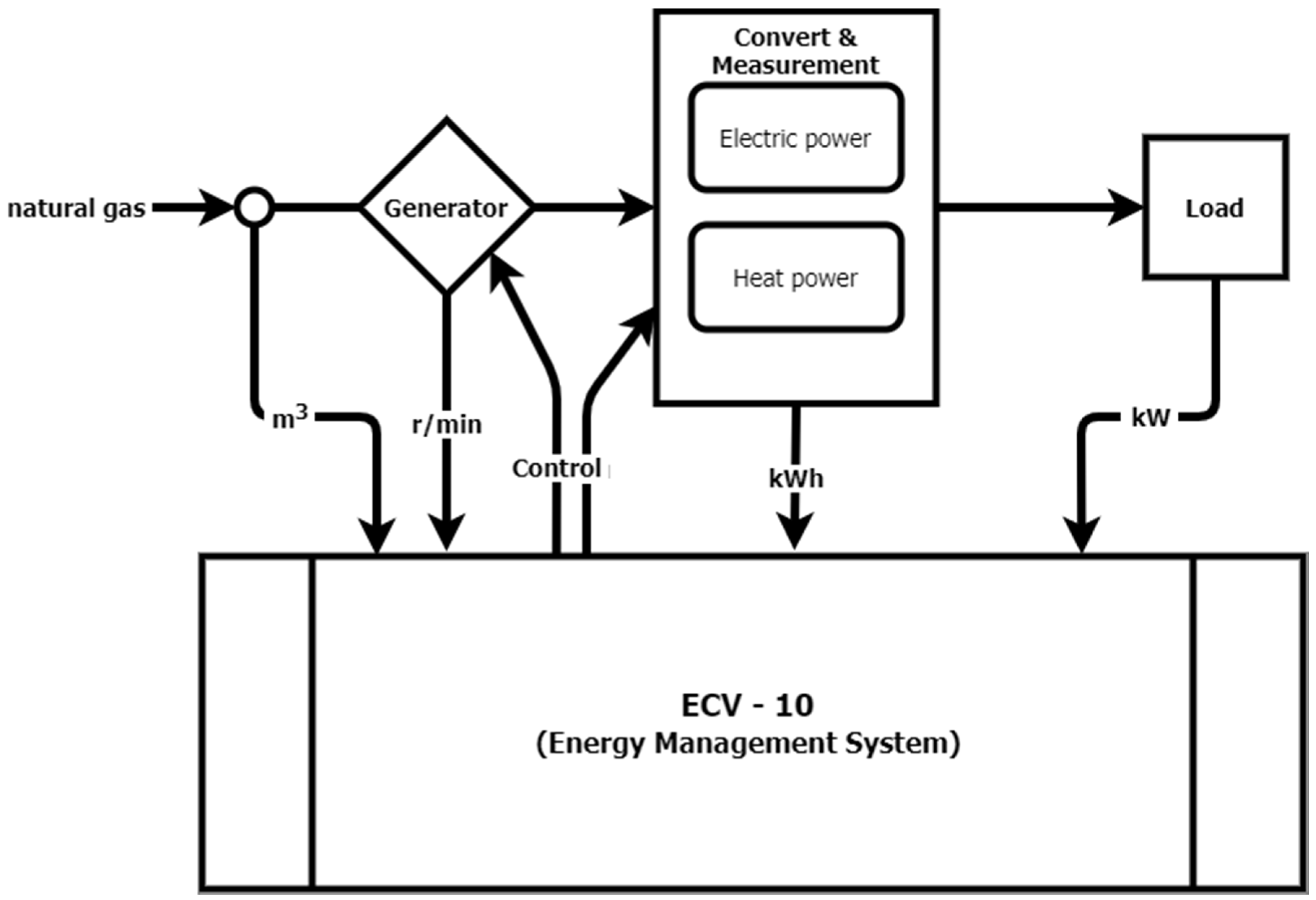
Assuming that the cogeneration system can only operate at the constant rotor speed of the generator, a constant power supply to the microgrid requires developing a new dedicated control system. The islanding mode of microgrid operation is not allowed by the basic control algorithm in these conditions. In accordance with the adopted assumptions and requirements, a new control system was developed that is able to operate in islanding mode by implementing a variable speed control system for the generator with efficiency optimization of energy conversion in the microgrid. The management of the energy generated and consumed by the microgrid is to be ensured, along with efficiency optimization of all microgrid subsystems. This is achieved by the development of a control system based on the energy management system implemented by the company (ECV–10), which, along with measurements of various physical quantities of the cogeneration system, allows the determination of the reference value for the generator rotor speed in the control system that will satisfy the requirements for electrical and thermal power. A brief description of the procedure to determine the efficiency is shown in
Figure 4. This procedure ensures obtaining maximum efficiency of cogeneration using the efficiency hill ἠ determined for the microgrid system in experimental tests of the cogeneration system operation range. On the basis of the acquired results, the optimal operating conditions of the connection and interchangeability of energy with the available rural grid were included in the control system. The efficiency hill of the cogeneration system (CHP) is the maximum efficiency derived from three variables: the generator rotational speed “
V”, related to fuel consumption; the maximum heat power “
PH”; and the electrical power “
PE”. It is defined as follows:
where
is the amount of natural gas related to the current rotational speed and
is the calorific value of natural gas (this parameter is assumed to be constant during system operation). Equation (1) allows the calculation of the efficiency hill from several real-time measurements of electrical and thermal energy, fuel consumption, and rotational speed, conducted using the experimental set-up shown in
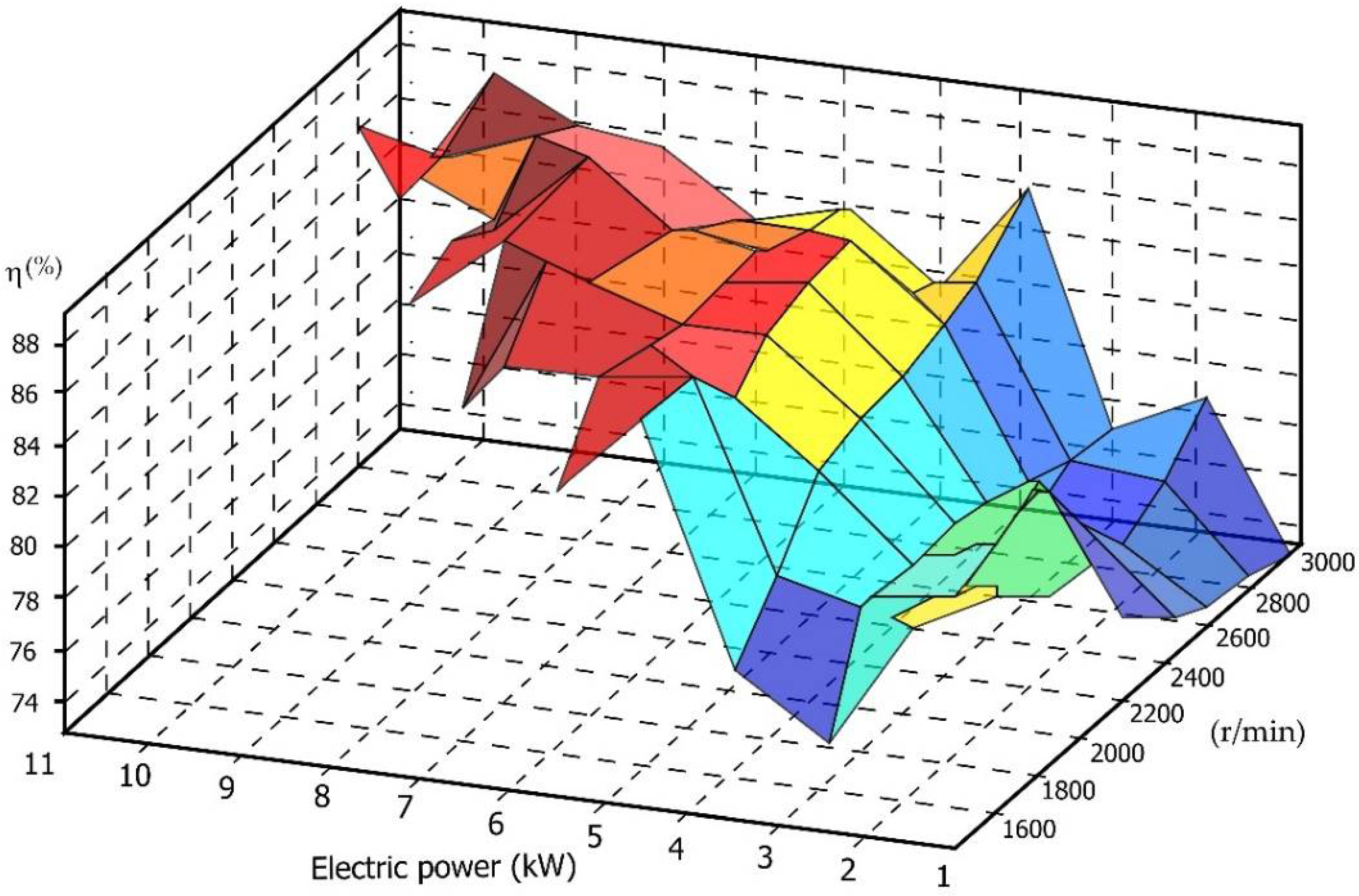
Figure 4. Based on the results obtained in the experimental tests, the efficiency hill was determined as illustrated in
Figure 5. Generally, the efficiency increases as the power and rotational speed increase; however some exceptions were identified. The algorithm for efficiency determination is reported in [
22].
Figure 6 presents the obtained curve reflecting the relation between electrical and thermal power in the cogeneration system. The average values of thermal and electric power shown in
Figure 6 were measured with a sampling period of T_s = 10 min.
Figure 7 shows the controlled state variables in the optimal efficiency hill tracking mode when the cogeneration system reaches the reference temperature of 80 °C (T
ref), starting from the initial temperature of 73.5 °C. The cogeneration system engine starts up and rapidly reaches a speed of 3000 rpm, which ensures a rapid increase in the temperature of the heat exchanger, where the desired temperature is attained within 300 s and kept stabilized at the reference value. The natural gas consumption increases during the transient state of temperature increase, and the thermal and electrical power increases as well.
In the islanding operation mode, the control system is required to provide the possibility of full control of internal energy consumption. Additional electric heaters, mounted in the production hall, are connected to ensure operation without losses of the generated energy when returning this energy to the rural power system is not possible and the storage system is fully charged.
Figure 8 shows the recorded voltage waveforms during switching from the on-grid rural power system connection operation to the off-grid islanding mode operation due to periods of unbalanced load related to varying energy consumption. The recorded voltage waveforms illustrate the presence of undesirable deformations caused by single phase welding machines. The implemented control algorithms ensured uninterrupted operation of the entire plant, even at significant asymmetry of load conditions. They provided safe switching to the islanding mode of operation, as shown in
Figure 8.
4. Analysis of Experimental Results
The developed energy management system presented in
Figure 9 has the functionality of data archiving. The microgeneration system was investigated for 5 years. Various algorithms of the energy management system were tested, along with different operational modes [
23]. A selection of data on the consumed and generated energy, as well as other factors affecting the assessment of the implemented EMS, is presented in
Table 1. Relative total energy balance analysis in years 2012–2016 is presented in
Table 2. For 2 years, long-term studies were carried out based only on the renewable energy acquisition systems with minimal use of the cogeneration system, the latter being initiated only for testing purposes. All predicted operation conditions were experimentally tested including the on-grid and islanding operation modes. Moreover, failure modes were simulated and diagnostic functionalities were tested. During the testing period, failure modes and safety shut-down procedures were identified and analyzed, including those resulting from atmospheric phenomena and rural power system failures. The summary of the supplied and consumed energy, with source distinction, is given in
Table 1.
Figure 10,
Figure 11,
Figure 12,
Figure 13,
Figure 14 and
Figure 15 show the data obtained in years 2012–2014 of the energy supplied to and consumed from the rural power system. These figures illustrate various modes of operation. It can be clearly noted that the much higher demand of energy observed in 2012 is due to the assembly and construction works carried out on the site, as shown in
Figure 10. In the following years, the assembly work was already finished. In 2014–2015, the research was conducted assuming no cogenerator operation, as it was turned-on only occasionally.
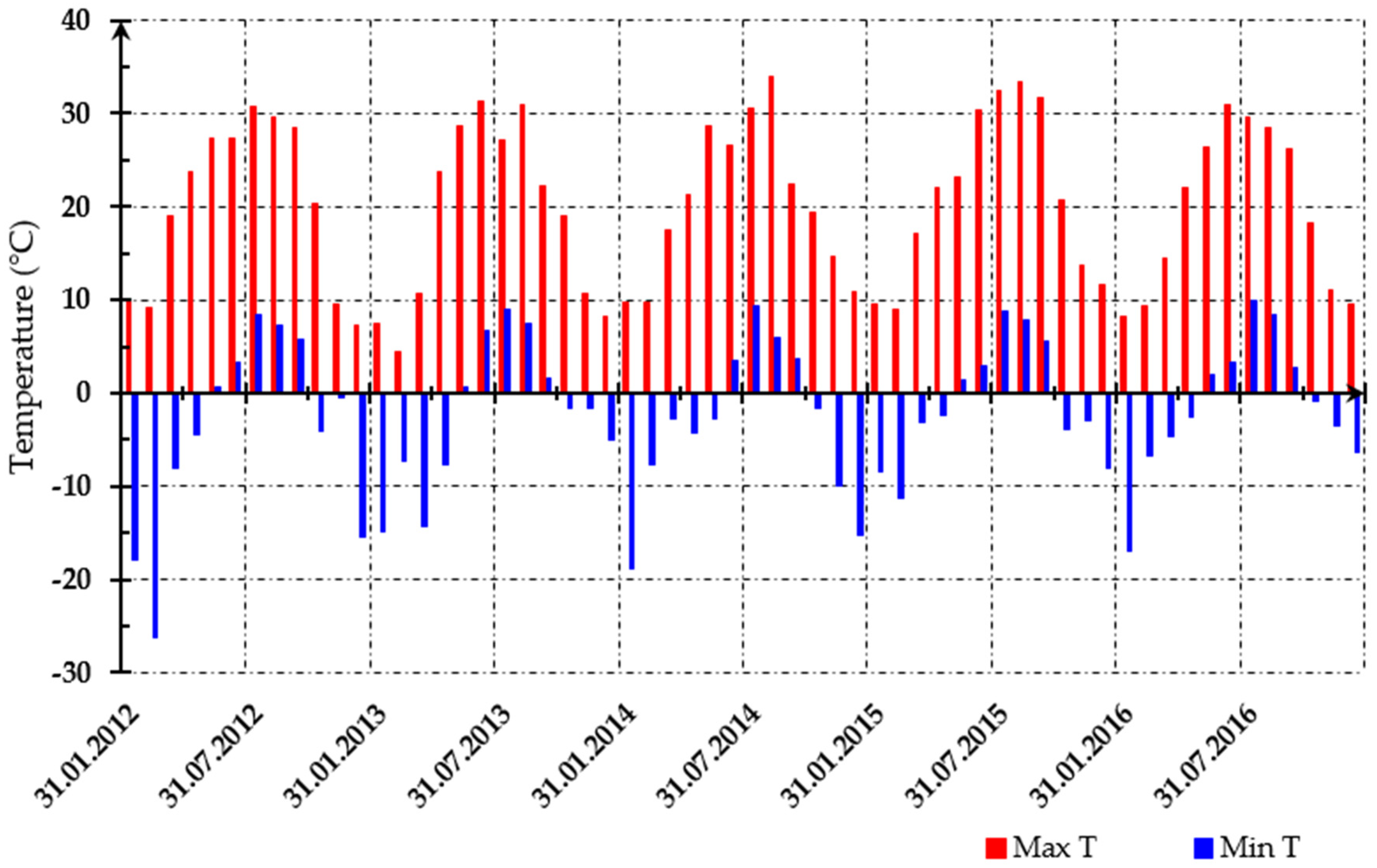
Figure 16 shows the maximum and minimum temperatures in the area of the company location, based on the measurements performed by the meteorological station located at Rębiechowo and owned by the IMGW (Polish Institute of Meteorology and Water Management—National Research Institute). The data was presented to indicate that in the observed period, the microgeneration grid was operated under temperature conditions typical for the geographical area of northern Poland where the company is located.
Table 1 presents the percentage shares of the energy produced from particular sources of the studied microgrid in the total energy consumption of the site.
Based on the data obtained during 5 years of study, it can be noted that the installed renewable sources, such as photovoltaics and wind turbines, can only contribute in completing the energy needs for local consumption to a minor extent. Most of the energy for self-power consumption on site was provided by the rural power system or the cogenerator system. However, it is noteworthy that various failures took place during different mode operations of the microgrid, but that thanks to the implemented energy management system, all malfunctions were detected and recorded, and corrective actions were automatically or manually undertaken. The identified and registered failures can be classified as follows:
In the case of rural power system failures, it was found that the operation of the microgrid system was not affected by this kind of failure, because the implemented EMS based on the developed control algorithm provided automatic, continuous, and smooth transition from the on-grid operation mode to the islanding operation mode. Switching between the on-grid and off-grid operation modes of the microgeneration system did not require any assistance. Depending on the duration of failure, the developed and adopted control algorithm allowed actions related to energy flow adaptation, covering the energy demand from available energy sources. The most serious identified failures were:
a cogeneration failure in 2016 due to incorrect operation caused by exceeding the time between planned periodic service inspections and lack of planned maintenance actions;
a battery failure in the energy storage system in 2016, which was caused by a service error that resulted in complete discharge of the batteries below 9.6 V. This failure occurred despite automatic microgrid disconnection from the energy storage system.
These failures were mainly caused by operational errors related to the human factor. If the system had been fully automated, the implemented algorithms would have prevented their occurrence. The human factor proved to be the most sensitive element of the system, causing all identified failures.
A microgeneration system comprising a cogenerator with supporting renewable energy sources, a photovoltaic module, and a wind turbine is a very good solution for small consumers using unstable power networks (e.g., rural areas, or places where high reliability of power supply is required). Moreover, the scheduled energy flow decreases the impact of a new wind farm connected to the grid, thus providing grid voltage stabilization in an admissible 2% fluctuation range. Therefore, wind turbines can be installed in places where the short-circuit power of the grid at the point of common coupling is not sufficient (this is actually the main argument against connecting a wind turbine to the grid). A microgrid can be utilized not only by the company to cover its energy needs, but also by the power system operator, especially in cases of high-power generation capabilities. The control algorithms developed for the microgeneration system ensure stable operation of the plant in various operating conditions, including on-grid and islanding operation modes. In cases of energy excess in the microgrid, it is possible to return the energy to the grid.
Due to accurate metering in the microgrid, several work profiles of the energy management system could be adopted. During the microgrid operation with the cogenerator, energy overproduction often occurred. In cases of microgrid operation using only renewable energy sources, the energy management system had to reduce energy consumption. The conditions regarding the modular structure of the energy management system that were taken into account at the beginning of its design turned out to be reasonable and proved that the adopted assumptions were correct. Based on the design and experimental tests of the microgrid, it was found that further versions of the system should include additional blocks for extended meteorological measurements of the photovoltaic system and wind turbines to more precisely predict energy generation. Upgrading the system with more extensive diagnostic functions significantly reduces the service support range; however, increasing the range of automation and admission is required to extend the permission range for control algorithms. The possibility of local data collection and storage is expanded and sending data on-line to the management server is achieved. It is assumed that the system should provide the ability to store all data for at least 1 month. This requirement is also valid for the verification of microgrid system service operator reactions to faults and alarm states, after the identification of some neglected actions. Due to the 5-year duration of the research, it was possible to accurately verify the data declared in the specifications for individual system components. For the cogenerator, it was found that the value of 15 kW declared in the specification by the manufacturer is not achievable. For the photovoltaic modules, the measurements also verified the parameters given in the specifications. The maximum expected power in summer was estimated to reach 1.5 kW, but the measurements showed peak power of as much as 2.2 kW. The aging effect in the photovoltaic modules was estimated. For the wind turbine, the rated power of 10 kW was never achieved. The turbine characteristic was not optimal for the wind speed range in the area. During the turbine operation, the average wind speed was 3–4 m/s (11–14 km/h), while the optimum operation speed declared by the manufacturer was 6–8 m/s (20–30 km/h). Accurate preliminary measurements of wind speed should be carried out at mast height in the planned location to select an optimal wind turbine. An error in the selection of optimal operational speed can reduce critically by over 50%, which is the amount of energy generated by the wind turbine compared to its rated power. It was also found that the assumption that limited the cogenerator operation profile as a heat source only to wintertime was not optimal. The conducted measurements clearly showed that to ensure the plant’s access to energy, the optimal assumption would be that the cogeneration system should operate all year round. In summer, it should provide heat supply for the air conditioning system based on absorption chillers, while in winter, it should deliver heating for the plant. An unforeseen issue was the lack of qualified service staff. Employment rotation has led to improperly trained and unexperienced service staff, an issue which is crucial in protecting the cogenerator from faults. The measurements also indicated that the energy management system should have greater autonomy.
5. Conclusions
Based on the developed microgrid system with cogenerator, wind turbine, photovoltaics, and energy storage, it was proven that a hybrid power generation system cooperating with the connected available rural power system is an adequate solution for small customers working in unstable power supply conditions, e.g., in rural locations, or places where high reliability of power supply is required. The developed energy management system was proven to be effective and achieved a number of advantages compared to the conventional microgeneration systems. The presented algorithms ensured stable operation of the plant in various working conditions, both in the case of operation with the available rural power supply and in the islanding operation mode. The schemes, topologies, and local and supervisory control systems presented, as well as the experimental results, are potentially useful for microgrid developers, scientists, and transmission network operators to address actual issues related to power balancing, supply voltage drops, and unintended PV inverters switching off. Experimental data are useful for comparing design assumptions and expectations of energy generation with long-term experimental results.


