Article

Grid and PV Fed Uninterruptible Induction Motor Drive Implementation and Measurements †

by
Ruben Rafael Boros
* and
István Bodnár
Institute of Physics and Electrical Engineering, University of Miskolc, 3515 Miskolc, Hungary
*
Author to whom correspondence should be addressed.
This paper is an extended version of our paper published in 2021 IEEE International Carpathian Control Conference, Ostrava, Czech Republic, 31 May–1 June 2021.
Energies 2022, 15(3), 708; https://doi.org/10.3390/en15030708
Submission received: 24 December 2021 / Revised: 15 January 2022 / Accepted: 17 January 2022 / Published: 19 January 2022
(This article belongs to the Topic Energy Storage and Conversion Systems)

Abstract

:
Motors powered directly from solar panels are becoming more and more popular in pump applications. However, solar panels can be the source of operational issues due to varying irradiance, ambient temperature, weather. This paper shows how it is worth expanding a solar induction motor drive to provide an uninterrupted flow of electricity to the motor. In addition, the main components of the uninterruptible induction motor drive are presented, including the LLC (inductor-inductor-capacitor) converter, the three-phase inverter, and the three-phase rectifier. LLC converters that can increase the voltage from 25–40 V to 330 V cannot be bought directly from manufacturers. Therefore, a custom LLC converter was made for the research. It was necessary to build a custom converter to avoid the use of solar panel strings. This way, solar panels connected in parallel can be used. A low-voltage (25–40 V) supply was implemented from the solar side, while the induction motor requires 230 V AC three-phase voltage in delta connection. For this reason, a voltage boost is required from the low voltage side. The grid feeds the universal DC link through the three-phase rectifier. This allows the motor to consume varying amounts of electricity from the grid or the solar panel. The study also presents in detail the LLC converter that performs the voltage boost. Measuring the entire motor drive, switching transients and efficiencies can be observed at different input voltages for different supplies as well as loads.

1. Introduction

Nowadays, the world’s demand for electricity is constantly increasing, while renewable energy sources are also becoming more and more widespread [1]. Solar panels allow efficient electricity generation over a relatively small area. Typically, the direct current and direct voltage produced by a solar panel are connected to a solar inverter that feeds electricity back into the grid or supplies electricity to the household. In some cases, solar panels are also used in island mode with batteries, in which case loads are fed directly from the solar panel and optionally from the battery through power electronic converter. Dynamic loads, such as electric motors, can cause control problems in electronic converters when powered solely by solar panels. Therefore, it is generally not advisable to power electric motor drives directly from solar panels, although it is worth to consider using them in lower power applications, such as in geothermal heat pumps, water pumps, heating circulating pumps, where three-phase or one-phase induction motors are usually used [2].
In Europe, dwarf three-phase induction motors (<1 kW) are in most cases designed for 230/400 V (delta/wye connection). The operating voltage of the solar panel is a few tens of volts, depending on the type. If voltage boost LLC converters are used, there is no need to form a solar panel string where several panels are connected in series to increase the voltage. Certain problems can occur when using solar panel strings if one of the solar panels is shaded and/or damaged. Shading a solar cell alone reduces the power of the entire string to a fraction when connected in series. Shading a single solar cell result in a much smaller power reduction when they are connected in parallel, than shading a cell of multiple cells connected in series. Due to this phenomenon, microinverters are used to feed back to the grid without needing to form a solar panel string. It is worth to mention that it is possible to form strings for low power motors (a few hundred watts), but not as cost-effective, since the unit cost of lower power solar panels are higher. Thus, it is worth to use higher power panels connected in parallel. An LLC converter is also required for solar panels connected in series and in parallel as well.
The voltage of a solar panel depends on many factors, such as the load, the solar irradiance, the temperature etc. On top of that, induction motors are AC loads; thus, an inverter is required to drive the motor from DC voltage and make it possible to adjust the speed of the motor. The electronic converter circuit must include a boost converter and an inverter. The boost converter generates stable high voltage from the fluctuating low-voltage of the solar panel, and then the inverter converts it to a three-phase alternating voltage for the motor with variable frequency. Depending on the size of the induction motors, the starting inrush current can be several times higher than the full load current, which means that the operating voltage of the solar panel changes abruptly. It is necessary to use a boost converter that can perform the formerly mentioned task with high efficiency. Using resonant LLC switching power supplies with good efficiency is sensible.
Efficiency is a crucial aspect of solar systems. Modern electronic converters can convert electricity with an acceptable efficiency; however, the efficiency of solar panels currently available on the market is not higher than approximately 20% [3]. Their efficiency, however, is increasing steadily as they are constantly being developed. The efficiency of dwarf induction motors is around 60–75%. Overall, it is worth installing solar fed motor drives in pump applications.
An induction motor drive powered directly from a solar panel cannot be considered reliable, since there is no constant sunlight in any particular area, and the solar irradiance itself changes dynamically. Operational safety can be greatly increased with batteries integrated into the system. However, even for low-power motors, several batteries are required for the pump to run overnight. It is reasonable to combine batteries with the use of electricity from the power grid, if available. This also increases operational safety since in the event of insufficient irradiance, the motor can just draw power from the grid. In addition, in the event of a grid failure, the motor can run on solar and/or battery power, so this system provides a versatile uninterrupted power supply to the motor [4]. Installing batteries in the system incurs an additional cost, as an MPPT controller is now required within the system. The battery system should be designed in a way that the solar panels charge the battery through the MPPT controller, and the LLC converter is powered from the battery.
Voltage boost LLC converters from 25–40 V to 330 V are not widespread, so it was necessary to build a custom converter for this research. Another advantage of a custom converter is that it does not require the use of solar panel strings. In this way, solar panels can be connected in parallel, if necessary. Moreover, this paper examines a solar and grid powered induction motor drive (Figure 1) in terms of electrical and mechanical efficiency and versatility. In theory, the following system can also be used for dwarf motors and high-performance motors. However, the size of the LLC converter increases greatly as its power increases, including the elements of the LLC tank. For this reason, it is worth using up to a few 10 kW.
The design of the LLC converter and the uninterruptible induction motor drive is presented in Section 2. The definition of the converters parameters is presented in detail. Section 3. details the hardware and software implementation of the LLC converter with PCB layout. The experimental setup used for the measurements is described in Section 4. Measurements are also presented where the LLC converter is powered by solar panel, from the power grid and from battery, as well as power supply. NI 9215 data logger with 0.2% accuracy was used with LabView software to measure the efficiencies. The torque and speed of the motor were measured by a SE2662-3S instrument and SE2662-1R magnetic powder brake from Lucas-Nülle. The efficiency of the motor was calculated from the ratio of the mechanical output power to the electrical power input. Mechanical performance was derived from the product of torque and angular velocity measured by the Lucas-Nülle device.

2. Designs

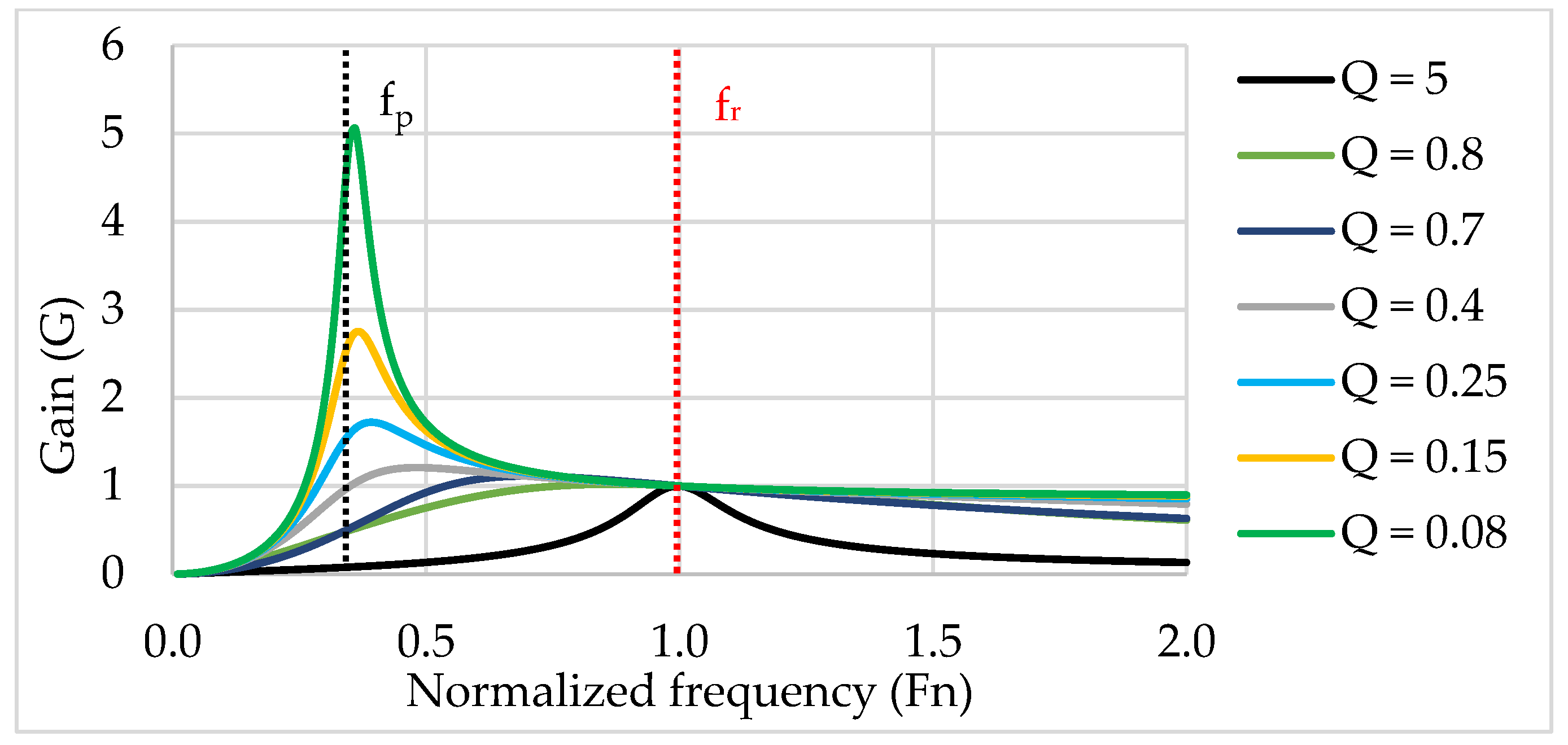
2.1. LLC Converter in General

The LLC converter is a resonant switching power supply that is widespread due to its high efficiency and relatively small size. LLC converters include a high-frequency transformer and external inductors, depending on the type. The LLC converters can also be used as a boost and buck converter as well. By increasing the switching frequency, the size of the transformer can be reduced, although the semiconductors operate with a higher switching heat loss, which results in higher cooling demand, a larger heat sink [5].
With resonant converters, the switching loss can be greatly reduced. In case of resonant converters, the semiconductors are switched when the voltage drop across the switching element is zero (ZVS: Zero Voltage Switching) or the current flow is zero (ZCS: Zero Current Switching). These switching modes result in soft switching on the semiconductor, so the dynamic power loss on the semiconductor is greatly reduced [5,6,7,8]. The LLC converters used operate in ZVS mode. This mode can be achieved in only inductive region. ZCS switching mode should be avoided. In this case, the current leads the voltage, so the current on the MOSFET flows in the reverse direction before the MOSFET turns off. After switching off, a large current would flow through the body diode. Hard commutation would then occur when a MOSFET in the bridge was turned on. This would result in a large recovery loss, noise and high current spike, which can result in device failure [7].
It is advisable to use the LLC full-bridge converter shown in Figure 2 for the task. A major advantage of the LLC converter is that in the case of a wide range of varying loads, the switching frequency only needs to be adjusted at a narrow interval, so it can be well controlled at a very low loads, or even without a load. It also has the additional advantage of low EMI noise due to soft turn off [5,6,7,8]. However, it is not always advisable to use resonant converters. It is worth using in medium power applications (few 10 kW), but above that the elements of the LLC tank would be very large and heavy.
A constant direct current (DC) is connected to the input of the LLC converter, which is applied to a single-phase inverter (DC/AC). The inverter consists of four (Q1, Q2, Q3, Q4) MOSFETs that produce alternating voltage with a 50% duty cycle. At the output of the inverter is the LLC tank, which converts the square wave voltage into sinusoidal voltage (AC/AC). The LLC tank circuit and the transformer increase or decrease together the voltage to the desired value (AC/AC). The AC voltage is applied to a full-bridge rectifier that provides DC voltage at its output (AC/DC) with a high ripple. Capacitor C0 smooths the ripple of the DC voltage. The load (R0) connected to the constant DC voltage [5,6,7,8].
Two magnetic components are required for the resonant circuit: the inductances Lr and Lm. Lr denotes the series resonant inductance, Lm the magnetizing inductance, which is shunt-like. Cr is the series resonant capacitance. It is also necessary to install a transformer for high gain. With the help of an integrated transformer, the inductances Lr and Lm can be implemented [5,6,7,8].
Consider Figure 3, which substitutes Figure 2 for the actual parameters of the transformer, i.e., the leakage primary and secondary and magnetizing inductances. It further simplifies Figure 2. At the bottom of the figure, in the simplified network, the transformer can already be considered ideal. The operation of LLC converters is also greatly influenced by leakage inductances (Ls1, Ls2). Although measuring leakage inductances is very difficult in practice, this is no longer necessary after simplification of the network. The parameter Lp can be determined by measuring the inductance on the primary winding of the transformer while the secondary side is open. The parameter Lr is similarly measured for a short-circuited secondary coil [6,7].
The appearance of the parameter Lr (resonant inductance) therefore stems from the simplification that can be determined according to Equation (1) [5,6,7,8].
L r = L s 1 + L m × ( n 2 · L s 2 ) = L s 1 + L m · L s 1 L m + L s 1
The parameter Lp (primary inductance) is also created, which combines the primary leakage inductance and the magnetizing inductance (Equation (2)) [5,6,7,8].
L p = L s 1 + L m
The magnetizing inductance can be given according to Equation (3), only two values of the result of the measurement on the transformer are required [5,6,7,8].
L m = L p L r
An important static parameter in the design of LLC converters is the m parameter, which can be changed to optimize the converter (Equation (4)). Reducing this parameter entails a reduction in the efficiency of the converter, a higher gain at the output, a narrower frequency range for control. Increasing the parameter m results in higher efficiency of the converter by a smaller magnetizing circulating current [5,6,7,8].
m = L p L r = L r + L m L r
Figure 3 also shows a RAC resistor corresponding to the load tested from the AC side (Equation (5)). Here, R0 stands for DC load and AV for virtual gain [5,6,7,8].
R AC = 8 π 2 · R 0 A v 2 = 8 · n 2 π 2 · V DC _ OUT 2 P 0
There are two resonant frequencies, these are derived from the Thomson formula (Equations (6) and (7)). The first resonant frequency is determined by the values of Lr, Cr and the second by the values of Lp and Cr [5,6,7,8].
f r = 1 2 π L r · C r .
f p = 1 2 π L p · C r
The quality factor of the resonant circuit is described by (Equation (8)) [5,6,7,8].
Q = L r C r R AC
Equation (9) gives the transfer function of the simplified network shown in Figure 3 [5,6,7,8].
G ( Q ,   m ,   F n ) = F n 2 ( m 1 ) ( m · F n 2 1 ) 2 + F n 2 · ( F n 2 1 ) 2 · ( m 1 ) · Q 2
The coefficient Fn represents the normalized frequency, which is the quotient of the frequency of the voltage supplying the resonant circuit and the resonant frequency (Equation (10)) [5,6,7,8].
F n = f s f r
The graphical representation of the transfer function is shown in Figure 4, where the static parameter m = 8 as an example. At different loads, we get various curves of the magnitude of the gain as a function of the normalized frequency.
As the load increases (RAC decreases), Q also increases. As the load increases the maximum of the curve (gain) decreases. The gain of the resonant circuit fed at the resonant frequency will be G = 1 regardless of the load. However, as the load decreases, the maximum of the curves are converging to the primary resonant frequency (fp). The gain G = 1 at the resonant frequency is only true if the secondary leakage inductance of the transformer is not considered, otherwise the gain changes slightly. The resonant frequency displays the virtual gain, denoted by AV (Equation (11)) [5,6,7,8].
A V = L p L p L r = m m 1

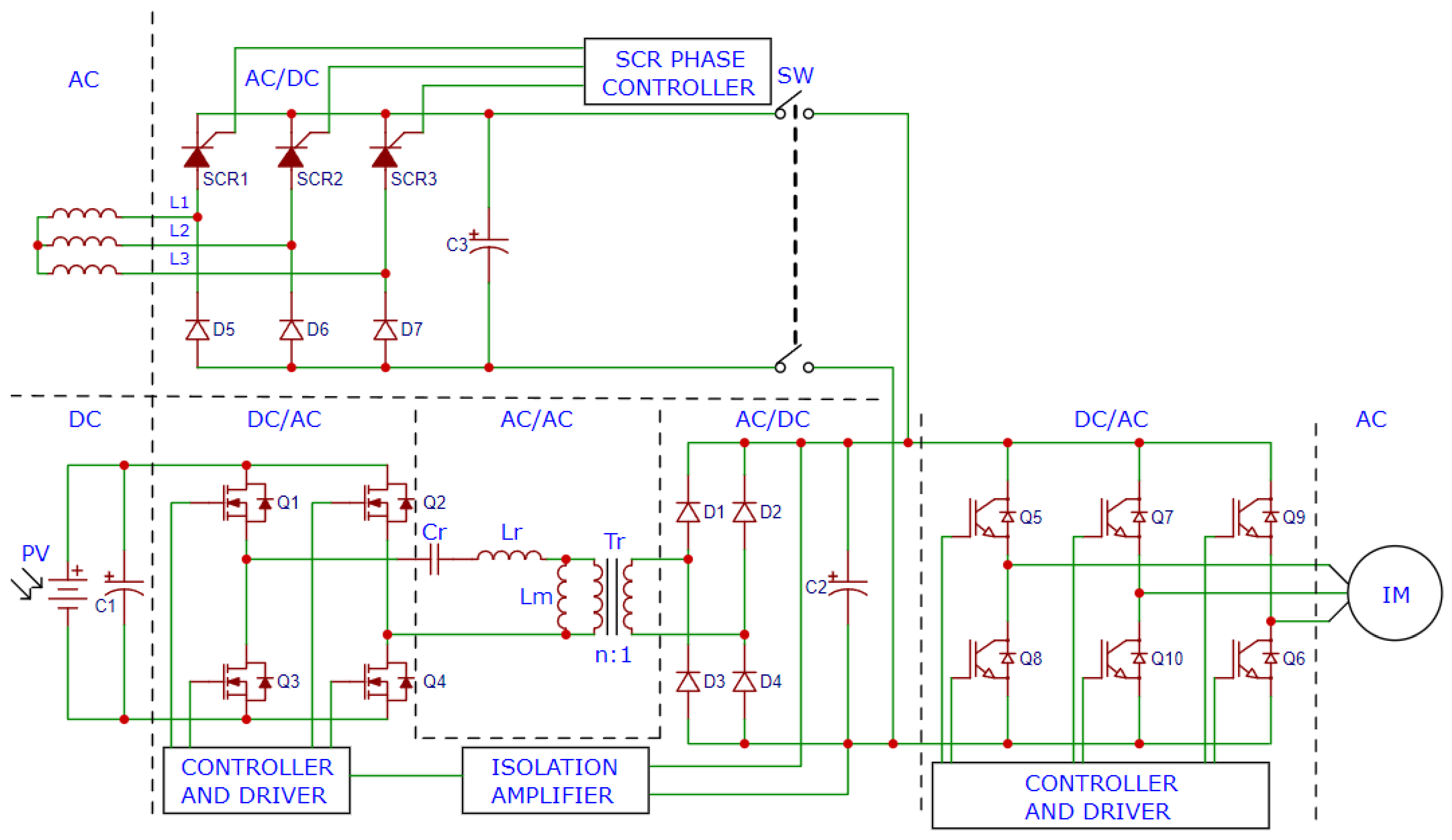
2.2. Uninterruptible Induction Motor Variable-Frequency Drive

Figure 5 shows the schematic diagram of the uninterruptible induction motor variable-frequency drive. The half-controlled three-phase rectifier is located at the top of the figure. It is advisable to use a three-phase rectifier due to the smoother DC voltage. An alternative solution is the single-phase full-bridge rectifier, which generates approx. 320 V DC at its output. The DC link can be considered universal, as different rectifiers, DC/DC converters and several inverters can be connected to it [9,10].
If the SW switch is closed, the DC link’s ground is not isolated anymore from the grid, but it is not a problem because the LLC converter’s transformer isolates the grid’s ground from the solar panel and the battery, and the grid can supply the DC link through the rectifier. From the DC voltage, the three-phase inverter generates variable-frequency voltage for the motor, thus controlling the speed of the motor. The DC link is also fed by the LLC converter which is located under the three-phase rectifier of the figure. With this circuit, three operating states can be achieved:
  • The LLC converter is turned off, only the rectifier is feeding the motor;
  • The rectifier is turned off, only the LLC converter is feeding the motor;
  • Both the rectifier and the LLC converter are simultaneously feeding the motor at a certain rate. The ratio depends on the magnitude of the voltage generated by the converters.
Since the motor is a dynamic load, it is necessary to monitor the voltage of the DC link which the single-phase inverter controls in the LLC converter [11,12]. Due to the load being dynamic, the quality factor and the gain also change fast. This is monitored by the resonant circuit control circuit through an isolation amplifier. The controller controls the frequency so that the output is set to 330 V. Meanwhile, the operating voltage of the solar panel also changes dynamically due to the changing irradiance as well as the load impedance [13].

2.3. LLC Converter Design for Induction Motor Variable-Frequency Drive

The first step in designing the LLC converter is to specify the input parameters. The amount of power required at the output must be declared. The aim of the study is to power dwarf three-phase induction motors of max. 400 W electrical power (Equation (12)).
P 0 = 400   W
The output voltage in the DC link must be 330 V to produce an effective voltage of 230 V at the output of the inverter for the motor, including losses. The motor must then be connected in a delta connection. The magnitude of the current flowing on the DC side and the magnitude of the DC load can be calculated (Equations (13) and (14)).
I DC _ OUT = P 0 V DC _ OUT = 400   W 330   V = 1.2121   A
R 0 = V DC _ OUT I DC _ OUT = 330   V 1.2121   A = 272.26   Ω
The maximum and minimum of the input voltage are both required input parameters. The circuit is powered by a solar panel with a maximum operating (nominal) voltage of around 29 V and a maximum power of 500 W at 1000 W/m2 irradiance. The lower limit was set at 25 V and the upper limit at 40 V. Based on these, the transformer ratio can be determined (Equation (15)). It requires the value of virtual gain already mentioned in Equation (11) of the study. The result is given by Equation (16). The m parameter was chosen to be 8 in this research for good efficiency. VF is the voltage drop of a diode in the rectifier bridge circuit (approx. 3 V).
n = V DC _ IN _ MAX V DC _ OUT + 2 · V F · A min = 40   V 330   V + 2 · 1.5   V · 1.0691 = 0.128414
A min = A V = m m 1 = 8 8 1 = 1.0691
The maximum gain must also be determined when the input voltage is the lowest (25 V in this case). Equation (17) can be used for this.
A max = A min · V DC _ IN _ MAX V DC _ IN _ MIN = 1.0691 · 40   V 25   V = 1.71
The quality factor (Q) is determined in the following way to reach the value of the maximum gain. It is necessary to substitute the initial values into the transfer function, plot the obtained function and then find the maximum of this (executed in Excel). Until then, the value of Q is iterated, even if the maximum of the function exceeds the value of Amax. However, it is important to mention that at the switching frequency used at the maximum of the function, the semiconductor switching elements do not operate in ZVS mode, so the efficiency is greatly reduced. In this case, it is worth increasing the value of Amax by 10%. Through the iterations, a value of Q = 0.232 was obtained, thus, covering the 10% oversizing. With a quality factor Q = 0.232 and a static parameter m = 8, the transfer function shown in Figure 6 is obtained. The figure also shows the minimum and maximum gain required (without oversizing). The maximum of the function is displayed at Fn = 0.39 (39 kHz), but at maximum load—due to the oversizing—47.6 kHz is required.
The value of the resonant frequency (fr) must also be specified. This value is limited by the properties of the semiconductors and the capabilities of the control circuit. A frequency of up to 100 kHz is still acceptable, with SiC MOSFETs, suitable drives and a high-speed microcontroller, henceforth fn = 100 kHz. Thus, the maximum gain is at 47.6 kHz. Equations (18)–(20) are required to determine the capacitive and magnetic parameters, as well as the value of the load from the AC side (Equation (22)). The magnetizing inductance is given by Equation (21).
C r = 1 2 · π · Q · f r · R AC = 1 2 · π · 0.232 · 10 5   Hz · 3.1842   Ω = 2154   nF
L r = 1 ( 2 · π · f r ) 2 · C r = 1 ( 2 · π · 10 5   Hz ) 2 · 2154 · 10 9   F = 1.1756   µ H
L p = m · L r = 8 · 1.1756   µ H = 9.405   µ H
L m = L p L r = 9.405   µ H 1.1756   µ H = 8.2294   µ H
R AC = 8 · n 2 π 2 · V DC _ OUT 2 P 0 = 8 · 0.1284 2 π 2 · 330 2   V 400   W = 3.184   Ω

3. LLC Converter Implementation

The implemented LLC converter is shown in Figure 7. The single-phase inverter MOSFETs (1.), power supply (2.), microcontroller (3.), transformer with external inductors (4.), full-bridge rectifier (5.), LLC tank capacitors (6.), voltage measurement circuits (7.), MOSFET’s gate driver with fault detection (8.) can be found on the printed circuit board.

3.1. Single-Phase Inverter

The single-phase inverter contains four NTHL060N090SC1 SiC MOSFETs with a static drain-source on-resistance of 60 mΩ (if VGS = 15 V). SiC MOSFETs are assembled on a heat sink. The relatively large heat sink is required because a high current (approx. 20 A at 25 V) flows at the input of the converter at full load, resulting in a high static power loss on the MOSFETs. The MOSFETs are controlled by an intelligent optodriver circuits (ACPL-352J) and isolated DC/DC converters (MGJ2D051505SC). This drive method also allows stable control above the resonant frequency (100 kHz). This method is necessary at the energy-free turn on.

3.2. LLC Tank and Transformer

The LLC tank circuit contains 27 pieces 82 nF in parallel connection, 1000 V foil capacitor, 6 pieces external inductor in parallel connection (PCV-0-472-10L, 4.7 µH) and the transformer as well. A total of 27 capacitors connected in parallel are needed to be able to operate at high current, as one capacitor can conduct max. 1.1 ARMS. The transformer must be sized for the lowest operating frequency (47.6 kHz), as this will be the maximum flux in the iron core. The type of iron core is EE65/65/27A ferrite. The transformer has n = 0.129 turns ratio. The primer winding has N1 = 4; the secondary winding has N2 = 31 number of turns. The iron core of the transformer consists of two pieces. The inductance Lp of the transformer can be adjusted with the air gap; however, the inductance Lr changes slightly. The inductance Lr depends to a large extent on the stray inductance of the transformer. The stray inductance must be made very large (compared with a normal transformer) in this case. The primary and secondary coils should be placed as far apart as possible. However, if this is not achieved, the stray inductance can be increased by inserting external coils. Therefore, 6 coils connected in parallel were installed. The air gap was set while measuring Lp inductance, so a very accurate result can be achieved. The plastic spacer and the iron core were assembled with ferrite glue. The following results were achieved: Lp = 9.4 µH, Lr = 0.39 µH. The resulting inductance of the six coils is 0.783 µH. This gives a total inductance of Lr = 1.173 µH. These values deviate very slightly from the design values, but it does not affect the operation.

3.2.1. Output Rectifier

At the transformer output, a four-piece SiC diode (STPSC15H12) creates a full-bridge rectifier. One diode has approx. VF = 1.5 V voltage drop. A buffer capacitor (330 µF) smooths the voltage at the rectifier output. A heatsink is not mounted on the diodes due to the output current being low (max. 1.22 A) and the diode recovery time is negligible.

3.2.2. Output Voltage Measurement Circuit and Microcontroller

The output voltage is monitored by the microcontroller using analog input. With ACPL-C87A optically isolated amplifier the voltage can measure safely. The amplifier circuit requires low-pass filter and isolated DC/DC converter. At the output of the isolated amplifier, a differential operational amplifier conditions the signal to the analogue input of the microcontroller. The type of microcontroller is STM32F103C8T6. Using the microcontroller timers, the control signals of the single-phase inverter can be easily generated. The timer frequency is set by a discrete PID controller. The setpoint of the PID controller is 330 V, for which the output is controlled by the microcontroller. The frequency is set between 47.6 kHz and 100 kHz depending on the magnitude of the load and the input voltage. The PID controller is set to turn off the single-phase inverter when the voltage reaches 390 V. This is required when the load is slight and the input voltage is nearly 40 V. As soon as the output drops below 340 V, the inverter switches on again. Filter capacitors are electrolytic capacitors with a high leakage current, so the output cannot be considered unloaded. Thus, the voltage oscillates between 390 and 340 V with a large time constant when no load connected. Figure 8 shows the flowchart of the implemented microcontroller’s algorithm.

4. Uninterruptible Induction Motor Drive Implementation

The uninterruptible induction motor drive and the experimental setup are shown in Figure 9. Several voltage sources were connected to perform different measurements. The figure shows the measurement powered by the battery and the grid. The motor has a mechanical power of 370 W, which can be loaded dynamically with any torque with a magnetic brake pad. The brake pad controller instrument indicates the actual speed and torque. Furthermore, the instrument has analogue output, thus, with four channel datalogger the actual mechanical and electrical power can measure at same time. From these, the efficiency can be determined.
The three-phase rectifier is half-controlled converter. It contains three thyristors (SCR) and three diodes. This rectifier is designed for previous research (max. output power is 10.56 kW), but it can also be inserted into the low power uninterruptible induction motor drive. The firing circuit is made up of pulse transformers. Thyristors are turned on by a microcontroller-timer circuit as a function of the desired firing angle. The firing angle directly controls the average value of the DC voltage. By changing the firing angle, the induction motor draws different proportions of electrical power from the grid and the LLC converter.
The three-phase inverter has already been built for previous research purposes. The inverter is designed to be universal. It contains 1200 V, 100 A IGBT modules with the corresponding driver circuit. The output of the LLC converter can be connected to the inverter’s DC link circuit. Potentiometers can be used to adjust the modulation index, which controls the motor voltage, the switching frequency, the first-order frequency, as well as ramp speed.

5. Measurements

In this section, the measurements of implemented circuits are described. The measurements confirm the correctness of the calculated values, examine the transients in time; thus, the stability of the PID control circuit can be examined. In addition, the efficiency of the LLC converter and the entire motor drive are determined.

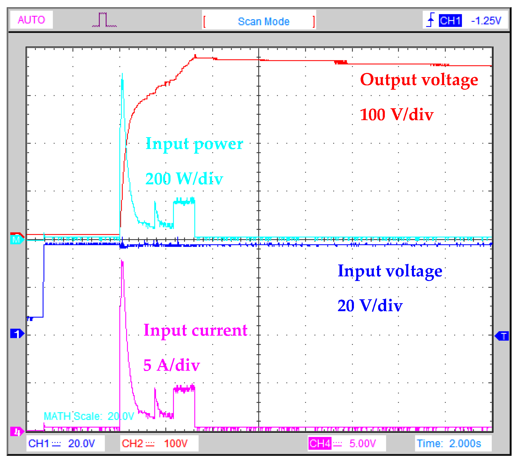
5.1. LLC Converter Energy-Free Turn on Transient

Turning on the energy-free LLC tank and output filter capacitor results in a large inrush current, as can be seen in Figure 10. At the moment of switching on, the microcontroller switches on the inverter with 160 kHz and then controls it at a frequency of 100 kHz for a short time, this ensures the lowest possible inrush current. During this time, the PID controller algorithm also starts and takes over the control. At this measurement, the LLC converter was fed by a 3 × 12 V lead-acid battery.

5.2. LLC Converter Normal Operation

The voltage and the current at the output of the inverter of the LLC converter are shown in Figure 11. In the figure on the left, there is a light load on the output, the inverter is controlled above the resonant frequency (>100 kHz). In the figure on the right, the inverter is controlled at a frequency close to the maximum gain when heavy load is applied at the output. The high oscillation in the voltage is due to the parasitic oscillation of the SiC MOSFETs. Oscillation occurs because the surge voltage resonates with the MOSFET’s drain-source parasitic capacitor (CDS), with stray inductance (LS) of printed circuit board wires and with the input filter capacitor. This oscillation is reduced by a snubber capacitor connected close to the MOSFETs to the input DC link. At this measurement, the LLC converter was fed by a 3 × 12 V lead-acid battery.
Figure 12 shows the output voltage at constant load. The voltage is kept stable by the PID controller. At this measurement, the LLC converter was fed by a 2 × 12 V lead-acid battery (23.9 V).

5.3. LLC Converter Fed by Solar Panel

An LLC converter powered directly with a solar panel is not preferred. On one hand, as the irradiance decreases, the maximum power that can be extracted from the solar panel also decreases. As the maximum power decreases, the voltage of the solar panel decreases. If the load is still constant, more current flows from the solar panel to the converter. This event is still well handled by the PID controller (Figure 13a). Sudden high-power consumption can cause the solar panel to reach its maximum current. In this case, the voltage of the solar panel is greatly reduced (below 25 V). This is handled by the PID controller by setting the frequency for maximum gain, however, the output voltage does not reach the setpoint. Once the overload has ceased, the output voltage stabilizes rapidly (Figure 13b). It is also possible to observe that the input current oscillates slightly under constant load. This is because the PID controller never controls the inverter with one frequency value, as the controllers also have oscillations. The oscillation amplitude depends on the value of the maximum power that can be extracted from the solar panel, so it depends on the irradiance. The oscillation of the PID controller changes the load on the solar panel, so the input voltage also changes.

5.4. LLC Converter Fed by Batteries and Solar Panel

The measurement of the battery-powered LLC converter is shown in Figure 14. In the figure on the left, the motor torque changes only slightly, while in the figure on the right, it changes suddenly. In the case of measurement, Figure 14a, the output voltage varied to a lesser extent than in the case of solar power supply, because at high input current, the battery terminal voltage decreases only slightly. This allows the PID controller to hold the output voltage more stably. Furthermore, in the event of an overload, the voltage will not drop due to battery power as in the case of solar power, as shown in Figure 14b. The output voltage decreases greatly under dynamic load because the output filter capacitor is slightly discharged. When the output voltage exceeds 390 V, the converter is off. If the induction motor is started without a soft start, the output voltage can be greatly reduced. In this case, the PID controller needs more time to charge the output capacitor to the setpoint. Once the converter is turned on, it responds more quickly to dynamic loads. A decrease in output voltage will have a negligible effect on motor operation. In this case, the motor voltage also decreases, with the result that the flux and, thus, the torque also decrease. A large drop in output voltage can be avoided if the motor is started softly and no mechanical load occurs instantaneously as shown in Figure 14a.

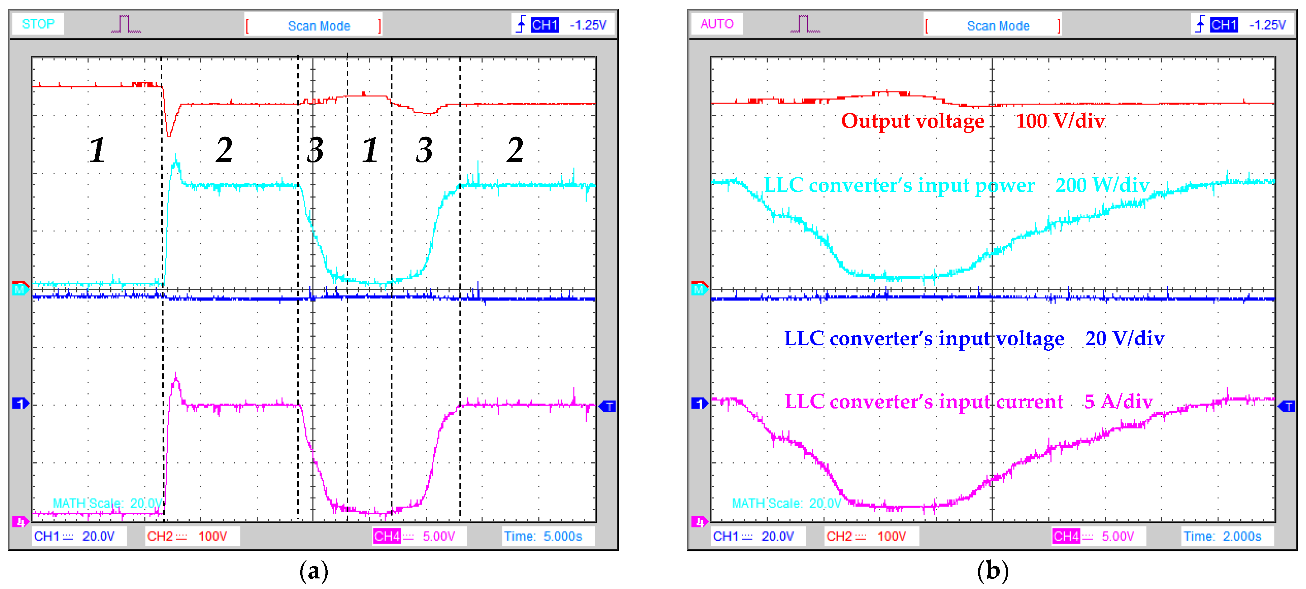
5.5. Uninterruptible Induction Motor Drive

The measurement of the uninterruptible induction motor drive are shown in Figure 15. During the measurement, the motor is loaded with constant torque at a constant speed. Figure 15a shows the three operating states:
  • The LLC converter is turned off, only the rectifier is feeding the motor;
  • The rectifier is turned off, only the LLC converter is feeding the motor;
  • Both the rectifier and the LLC converter are simultaneously feeding the motor at a certain rate.
At the beginning of the measurement, the rectifier supplies a DC voltage of 350 V to the DC link. The LLC converter was then set to a 320 V setpoint, so its output is turned off by the control circuit, so electricity only comes from the grid to the three-phase inverter. The three-phase inverter monitors the voltage of the DC link, so it is not a problem that the DC voltage rises above 330 V. The inverter uses pulse width modulation to reduce the motor voltage so that the iron core will not be saturated. Operating state 1 can only be achieved if the rectifier produces a higher voltage than the LLC converter. In contrast, diodes and thyristors do not open.
The measurement examines the sudden change from the first operating state to the second operating state. The rectifier will then turn off completely, simulating a grid power outage. The LLC converter immediately turns on and charges the output capacitor and maintains the voltage at 320 V.
The rectifier then turns on and the firing angle decreases slowly, causing the output voltage to increase. The rectifier and the LLC converter feed the three-phase inverter in different proportions. This ratio can be adjusted with the firing angle. If the voltage rises above 320 V, the LLC converter continuously increases the frequency of the LLC tank, thus decreasing the amount of voltage generated by the LLC converter. Figure 15b shows this process back and forth over a longer period (operating stages: 2 → 3 → 1 → 3 → 2).

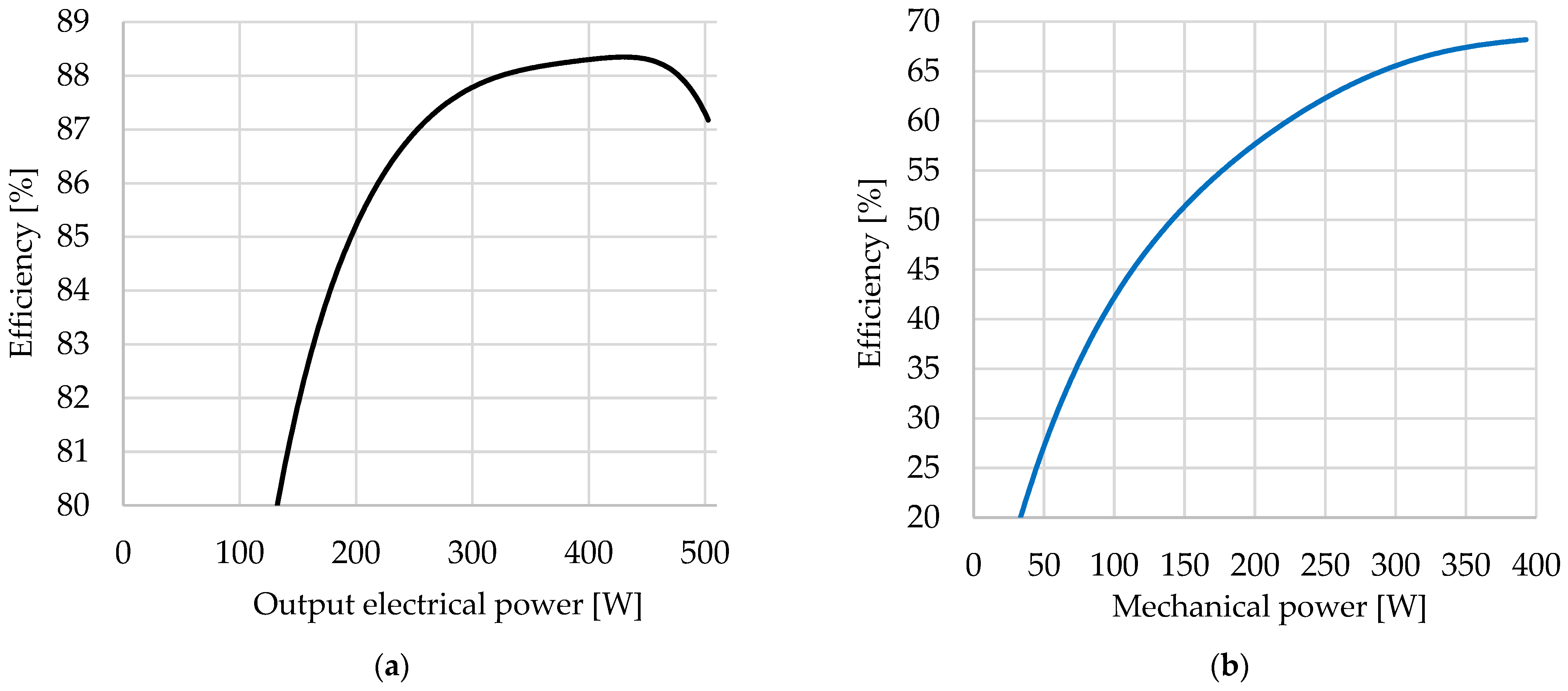
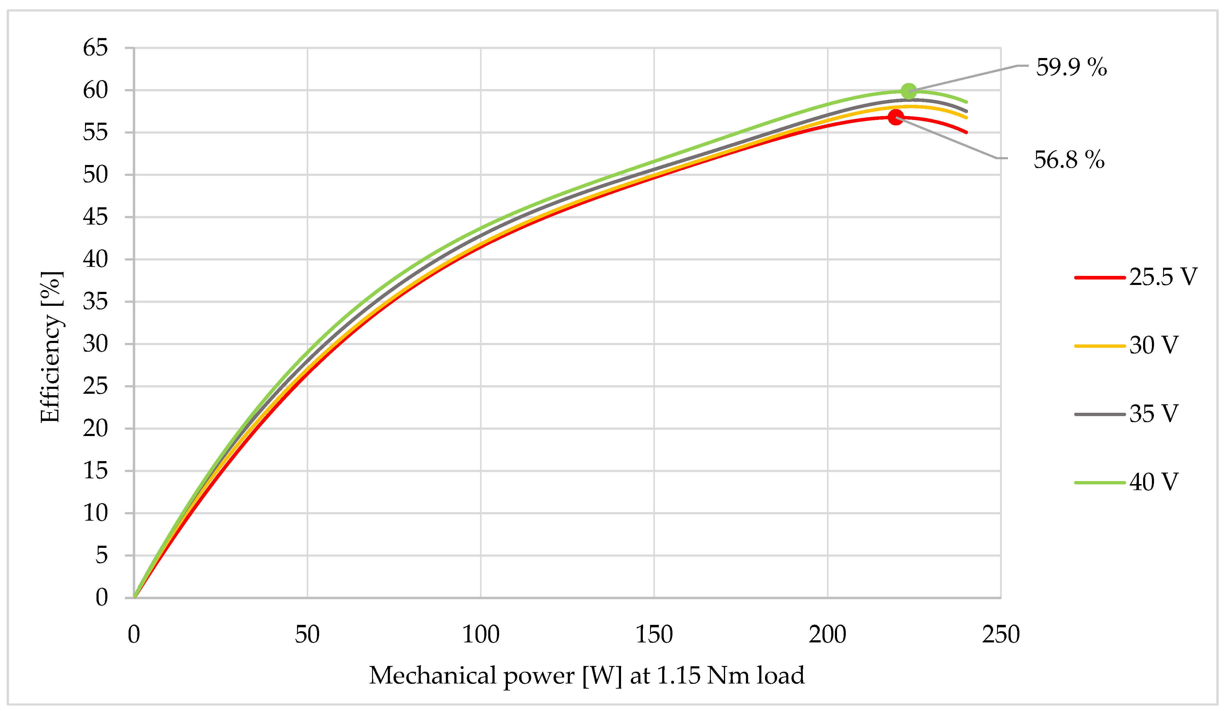
5.6. Efficiency Measurements

The left side of Figure 16a shows the efficiency measurement of the standalone LLC converter. The figure on the right Figure 16b shows the efficiency between the input of the LLC converter and the mechanical power measured on the motor shaft. During measurement Figure 16a, the LLC converter was operated at approximately 505 W output power, when the input power is 580 W (at Vin = 40 V). The converter can be overloaded due to the large heat sink. There is a difference between the efficiencies of a voltage boost LLC converter and a voltage drop LLC converter with the same power. A higher efficiency can be achieved with a voltage reducing LLC converter [14,15,16]. This is because their input voltage is higher, but the input current is lower. At lower currents, the power loss on the MOSFETs is significantly lower. The efficiency of the presented voltage boost LLC converter is lower due to the relatively high current at the input and the high channel resistance of the MOSFETs. These result in a large static power loss.
The efficiency of the 370 W induction motor used during the measurement was approx. 80.4% at the maximum load. As the load torque decreases, the efficiency also decreases. In the following, it can be seen in Figure 17 how the efficiency varies between the mechanical power of the motor and the input of the LLC converter at different input voltages. During the measurement, the rated torque was not applied to the motor, only 1.15 Nm. The speed varied from 0 to 2000 RPM, which was set by the variable frequency drive. As the input voltage decreases, the efficiency also decreases, as a higher input current is required to achieve the same mechanical power. Due to the higher current consumption, the static power loss increases, resulting in reduced efficiency.

6. Discussion and Conclusions

In summary, the uninterruptible induction motor drive is working properly and stable. The measurements were made under different conditions, as the LLC converter was also powered by a battery, solar panel and power supply. However, this does not affect the result of the demonstration that the uninterruptible induction motor drive can be used reliably at low power. During the measurements, no condition occurred when the LLC converter was powered by a solar panel and a battery at the same time. This is because an electronic converter that charges the battery with the DC voltage generated by the solar panel has not yet been completed. Research is currently underway to create an MPPT (Maximum Power Point Tracking) control circuit that can handle dynamic loads well. By implementing the MPPT circuit, it is possible to power the LLC converter from a solar panel and a battery at the same time. In terms of measurements, it seems that it is not worthwhile to power the LLC converter from a solar panel alone, as achieving continuous rated power is not guaranteed. The solar panel would be able to supply the battery and the LLC converter simultaneously if an MPPT control circuit was also installed. In the event of a sudden power consumption, the batteries will withstand this without any problems, so that the voltage of the solar panel will not drop greatly. Conventional MPPT controllers do not fit well with this system, as sudden power consumption can occur in this case, this control algorithm cannot handle it properly, so research is focused on developing a new type of MPPT controller in the future. In the previous research, where the LLC converter was designed in theory and the parameters were checked by simulation, an efficiency of 90.6% was obtained. The implemented converter achieved an efficiency of 88.3%. In the simulation, the capacitors, inductors, the transformer was ideal, so in reality it is therefore less efficient. Furthermore, the power supply of the LLC converter electronics is also covered from the input and this was not set in the simulation. The driver circuit of the power MOSFETs consume the most power from the auxiliary power supply.
The efficiency of the entire drive could otherwise be improved if the LLC converter was supplied from a higher input voltage. However, an additional cost would occur as more batteries and solar panels would be required. The efficiency would not increase significantly though, as the lowest efficiency in the system is the motor. Another possible way to increase the efficiency is replacing the voltage-hertz control algorithm in the three-phase inverter with Fuzzy-logic Field-Oriented Control [17,18].

Author Contributions

Conceptualization, R.R.B. and I.B.; software, R.R.B.; validation R.R.B. and I.B.; formal analysis, R.R.B.; investigation, R.R.B.; resources, R.R.B. and I.B.; data curation, R.R.B.; writing—original draft preparation, R.R.B.; writing—review and editing, R.R.B.; visualization, R.R.B.; supervision, I.B.; project administration, I.B. All authors have read and agreed to the published version of the manuscript.

Funding

This research received no external funding.

Institutional Review Board Statement

Not applicable.

Informed Consent Statement

Not applicable.

Data Availability Statement

Not applicable.

Conflicts of Interest

The authors declare no conflict of interest.

References

  1. Hasanuzzaman, M.; Zubir, U.S.; Ilham, N.I.; Seng Che, H. Global electricity demand, generation, grid system, and renewable energy polices: A review. WIREs Energ. Environ. 2016, 6, 18. [Google Scholar] [CrossRef]
  2. Frivaldsky, M.; Kascak, S.; Morgos, J.; Prazenica, M. From Non-Modular to Modular Concept of Bidirectional Buck/Boost Converter for Microgrid Applications. Energies 2020, 13, 3287. [Google Scholar] [CrossRef]
  3. Derbeli, M.; Napole, C.; Barambones, O.; Sanchez, J.; Calvo, I.; Fernández-Bustamante, P. Maximum Power Point Tracking Techniques for Photovoltaic Panel: A Review and Experimental Applications. Energies 2021, 14, 7806. [Google Scholar] [CrossRef]
  4. Adamczyk, M.; Orlowska-Kowalska, T. Virtual Current Sensor in the Fault-Tolerant Field-Oriented Control Structure of an Induction Motor Drive. Sensors 2019, 19, 4979. [Google Scholar] [CrossRef] [PubMed] [Green Version]
  5. Rafael, R.B.; Istvan, B. LLC Resonant Converter Design and Simulation for PV Motor Drives. In Proceedings of the 2021 22nd International Carpathian Control Conference (ICCC), Ostrava, Czech Republic, 31 May–1 June 2021; pp. 1–5. [Google Scholar]
  6. Escudero, M.; Kutschak, M.-A.; Pulsinelli, F.; Rodriguez, N.; Morales, D.P. On the Practical Evaluation of the Switching Loss in the Secondary Side Rectifiers of LLC Converters. Energies 2021, 14, 5915. [Google Scholar] [CrossRef]
  7. Sam, A.-R. Resonant LLC Converter: Operation and Design. Infineon 2012, 1, 19. [Google Scholar]
  8. Hang-Seok, C. Half-Bridge LLC Resonant Converter Design Using FSFR-Series Fairchild Power Switch (FPSTM); Fairchild: Sunnyvale, CA, USA, 2007; p. 20. [Google Scholar]
  9. Shukla, S.; Singh, B. Single Stage PV-Grid Interactive Induction Motor Drive with Improved Flux Estimation Technique for Water Pumping with Reduced Sensors. IEEE Trans. Power Electron. 2020, 35, 12988–12999. [Google Scholar] [CrossRef]
  10. Shukla, S.; Singh, B. Grid-PV Array Fed Induction Motor Drive for Water Pumping. In Proceedings of the 2018 IEEE International Conference on Power Electronics, Drives and Energy Systems (PEDES), Madras, India, 18–21 December 2018; p. 6. [Google Scholar]
  11. Abdelwanis, M.I.; Rashad, E.M.; Taha, I.B.M.; Selim, F.F. Implementation and Control of Six-Phase Induction Motor Driven by a Three-Phase Supply. Energies 2021, 14, 7798. [Google Scholar] [CrossRef]
  12. Wu, Z.; Gao, C.; Tang, T. An Optimal Train Speed Profile Planning Method for Induction Motor Traction System. Energies 2021, 14, 5153. [Google Scholar] [CrossRef]
  13. Cortés, B.; Tapia, R.; Flores, J.J. System-Independent Irradiance Sensorless ANN-Based MPPT for Photovoltaic Systems in Electric Vehicles. Energies 2021, 14, 4820. [Google Scholar] [CrossRef]
  14. Yang, C.; Liang, T.; Chen, K.; Li, J.; Lee, J. Loss analysis of half-bridge LLC resonant converter. In Proceedings of the 1st International Future Energy Electronics Conference (IFEEC), Tainan City, Taiwan, 2–6 November 2013; p. 6. [Google Scholar]
  15. Wang, Q.; Zhang, X.; Burgos, R.; Boroyevich, D.; White, A.; Kheraluwala, M. Design considerations for a high efficiency 3 kW LLC resonant DC/DC transformer. In Proceedings of the IEEE Energy Conversion Congress and Exposition (ECCE), Montreal, QC, Canada, 20–24 September 2015; pp. 5454–5461. [Google Scholar]
  16. Schmidt, O.R.; Myhre, E. 380Vdc/48Vdc/ 3kw DC/DC converter with 98.2% efficiency. In Proceedings of the IEEE International Telecommunications Energy Conference (INTELEC), Osaka, Japan, 18–22 October 2015; pp. 1–6. [Google Scholar]
  17. Eltamaly, A.M.; Alolah, A.I.; Badr, B.M. Fuzzy controller for three phases induction motor drives. In Proceedings of the International Conference on Autonomous and Intelligent Systems, Povoa de Varzim, Portugal, 21–23 June 2010; p. 6. [Google Scholar]
  18. Eltamaly, A.M.; Alolah, A.I.; Hamouda, R.; Abdulghany, M.Y. A novel digital implementation of AC voltage controller for speed control of induction motor. Int. J. Power Energy Convers. 2010, 2, 78–94. [Google Scholar] [CrossRef] [Green Version]
Figure 1. Grid and PV fed uninterruptible induction motor drive.
Energies 15 00708 g001
Figure 2. LLC full-bridge converter.
Energies 15 00708 g002
Figure 3. Simplified LLC full-bridge converter.
Energies 15 00708 g003
Figure 4. Gain as a function of normalized frequency under different loads.
Energies 15 00708 g004
Figure 5. Schematic diagram of the uninterruptible induction motor variable-frequency drive.
Energies 15 00708 g005
Figure 6. The transfer function with the designed values at maximum load.
Energies 15 00708 g006
Figure 7. The implemented LLC converter.
Energies 15 00708 g007
Figure 8. Flowchart of the implemented algorithm.
Energies 15 00708 g008
Figure 9. The implemented uninterruptible induction motor drive with mechanical load.
Energies 15 00708 g009
Figure 10. Energy-free turn on transient when no load is applied at the output.
Energies 15 00708 g010
Figure 11. LLC converter at normal operation: (a) at resonant frequency with light load when f = 119.3 kHz; (b) at heavy load when f = 48.17 kHz.
Energies 15 00708 g011
Figure 12. Input voltage, current and the output voltage at constant mechanical load.
Energies 15 00708 g012
Figure 13. LLC converter fed by solar panel: (a) irradiance slightly decreasing; (b) solar panel overloaded operating condition.
Energies 15 00708 g013
Figure 14. LLC converter fed by batteries: (a) the torque changes slowly; (b) the torque changes suddenly.
Energies 15 00708 g014
Figure 15. Uninterruptible induction motor drive measurement: (a) three operating states; (b) the rectifier’s firing angle changes slowly.
Energies 15 00708 g015
Figure 16. Efficiency: (a) between LLC converter input power and output power; (b) between LLC converter input power and motor’s mechanical power.
Energies 15 00708 g016
Figure 17. The total efficiency for different input voltages when the torque constant 1.15 Nm (the RPM changes 0–2000).
Energies 15 00708 g017
Publisher’s Note: MDPI stays neutral with regard to jurisdictional claims in published maps and institutional affiliations.

