Article

A Study of the Thin Film-Coated Swelling Retarding Particles in Fractured Carbonate Reservoirs for Water Plugging and Profile Control

College of Petroleum Engineering, Yangtze University, Wuhan 430100, China
*
Author to whom correspondence should be addressed.
Energies 2022, 15(3), 1085; https://doi.org/10.3390/en15031085
Submission received: 7 December 2021 / Revised: 5 January 2022 / Accepted: 25 January 2022 / Published: 1 February 2022
(This article belongs to the Topic Enhanced Oil Recovery Technologies)

Abstract

:
T oilfield is the fractured-vuggy carbonate reservoir at a temperature of around 130 °C, with salinity of up to 22 × 104 mg/L. In order to solve the problem of the high water cut in the late development stage of T oilfield, we selected XN-T from 27 kinds of swelling retarding particles by testing their swelling capacity, and coated a thin film to improve its retarding swelling capacity. The mechanisms of strong water absorption and water-holding abilities of particles were analyzed by infrared spectrometry and SEM. In the core flow experiment, the plugging rate was found to be 98.42%. Finally, the injection parameters of the coated particles were optimized to maximize the water plugging and profile control ability, resulting in an optimal particle size of 0.4–0.6 mm and a mass fraction of 10%.

1. Introduction

Global reserves of oil and gas in carbonate reservoirs account for about 40% of the total oil and gas reserves in the world, and the output of oil and gas in carbonate reservoirs is as high as 60% of the gross oil and gas output [1]. The carbonate reservoirs of T oilfield are more than 5300 m deep at temperatures around 130 °C; the salinity of formation water is (19–23) × 104 mg/L. They exhibit very strong heterogeneity. The storage-permeation spaces vary greatly in shape, size, and distribution; and the reservoirs mainly consist of fractured, fractured-vuggy, and vuggy reservoirs [2]. One of the major problems in development is too fast a rise in water cut in the oilfield; thus, profile and water control are key to improvement of the overall development and oil recovery efficiency of oilfields [3].
Bai et al. [4] studied the migration modes of retarding swelling particles in porous media. When the particle diameter is larger than the pore diameter, there are four migration modes: (1) in situ plugging, no migration; (2) passing after elastic deformation; (3) water loss, re-swelling after passage; (4) after shearing and breaking through. Additionally, by designing pore model experiments, Bai et al. concluded that the ratio of particle size to pore diameter of particles passing through the pore throat mainly ranges from 2 to 4. When the value is greater than 5, the particles will be sheared through the throat. This conclusion shows that the transport mode of particles differs with particle size and pore diameter ratio. Li et al. [2] designed the oil displacement experiment for the visual model of a fractured reservoir, and found that the swelling retarding particles achieved step-by-step plugging and flooding regulation through plugging–migration–resealing–remigration. At the same time, the pressure difference between the two ends of the fracture urged the particles to accumulate at the fracture entrance, thereby effectively causing plugging. Li et al. [5] used a sand filling pipe with four pressure measuring points to study the relationships between plugging effect and particle size and pore diameter. It was found that conventional swelling retarding particles were difficult to inject into the sand filling pipe, and generally accumulated in the front of the sand filling pipe to form a filter cake, which indicated that swelling retarding particles were not applicable in non-fractured reservoirs. According to the 1/3 bridging rule and 2/3 bridging rule, the particle size of swelling retarding particles is only a few to tens of microns, which also proves that swelling retarding particles are suitable for fractured reservoirs.
At present, due to the temperature resistance and salt resistance of the swelling retarding particles, they are better off in high-temperature, high-salt, fracture-type reservoir applications than in a polymer freeze gel. The Xing-724 well in Daqing oilfield was in the high water cut stage before profile control, where the reservoir is thin and the vertical heterogeneity is strong. The total thickness accounts for 1/5 of the high permeability layer, and its water absorption accounts for 85% of the total. After the use of swelling retarding particles, the cumulative increase of oil was 2400 t, and the water content was reduced by 8% [6]. Pu et al. [7] prepared a new type of polymer/retarding swelling particle via intercalation in situ polymer method. The swelling ratio of the composite material can reach 13–62, the temperature resistance can reach 90 °C, and the salt resistance can reach 250 g/L. Through field tests of two well groups in Dagang (fractured reservoirs), the oil production was increased by 2400 t. Yu et al. [8] reported the application of swelling retarding particles in fractured, low-permeability reservoirs. The plugging rate of swelling retarding particles in laboratory experiments was 91.32%. In the presence of large fracture channels with permeabilities of up to 33,153 D in Jilin Oilfield, the combination of swelling retarding particles and a two-type polymer gel was used to increase oil production by 1878 t and reduce water content by 9.73% in two wells. In laboratory research, Tang et al. [9] developed high-strength particles having an interpenetrating network system. They have a swelling time longer than 20 d at 45 °C and maintain long-term stability at 80 °C, though their heat and salinity resistance are deficient. By using a composite crosslinker to form a three-dimensional structure with polymeric chains, Cui [10] developed a novel type of heat-resistant, PAA, swelling retarding particles. In distilled water at 250 °C, the maximum swelling ratio of 340 was achieved at 6 h, and then the swelling ratio became stable until 25 h, though its long-term stability and salt tolerance were not studied by the researcher. Wang et al. [11] developed a novel type of low-cost swelling retarding particles that cost 50% less than the standard alternative. In formation water at 60 °C with a mineral salt concentration of 6 × 10⁴ mg/L, the maximum swelling ratio of 16.8 was achieved at 30 h, and then the swelling ratio could still remain at 13.0 after 100 d. Bai et al. [12,13] developed a type of novel thermally degradable particles. After injecting them into the formation water, they plugged the high permeability layers and transformed the water into a viscous polymer solution for a certain time interval as a fluidity control agent for deep reservoirs. Since then, they further developed re-crosslinkable “smart particles” that can be polymerized again into large gels under shearing; however, the applications of such particles are still immature.
Laboratory tests and practice have proved that in heavy, heterogeneously fractured reservoirs, much higher oil content and lower water content can be obtained after using swelling retarding particles alone or gel-swelling retarding particles in combination. However, before this study, there were no swelling retarding particles that could perform excellent water plugging and an increase in oil content in a high-temperature and high-salt reservoir such as T oilfield, while having long-term stability. The thin film-coated XN-T provides an important option for water plugging and dissection operations in high-temperature and high-salt reservoirs.

2. Experimental

2.1. Materials

Swelling retarding particles: 27 types of swelling retarding particles frequently used in commercial oilfields were purchased. The list is shown in Appendix A Table A1.
Water for experiment: Simulated formation water of the T oilfield with a total salinity of 223,802.8 mg/L, where mass concentrations (mg/L) of various ions are described as follows: Na++K+: 73,298.4, Ca2+: 11,272.5, Mg2+: 1518.8, Cl: 137,529.5, and HCO3: 183.6.

2.2. Methodology

2.2.1. Preparation of Particle Suspensions

Each particle suspension was prepared by weighing method: based on the required concentration and amount for the study, a given mass of dry particles was weighed and then added slowly into a given volume of the simulated formation water under magnetic stirring; 3 min later, the stirring stopped, and the dispersion system was placed in a thermostatic water bath to let stand.

2.2.2. Retarding Swelling Performance Test

(1)
Twenty-seven types of purchased swelling retarding particles were dried in an oven at 105 °C for 2 h;
(2)
For each type of swelling retarding particles, n parts of it were weighed out on an electronic balance, and the weight of each part was denoted as m0 (accurate to 0.01 g), so n parts of particle suspensions were prepared;
(3)
With a straw or funnel, 20 mL of each part of suspension was aspirated into a 30 mL ampoule;
(4)
The ampoule was sealed using an alcohol blast burner;
(5)
The ampoule was put into a 500 mL aging tank;
(6)
The aging tank was placed in the oven at 130 °C;
(7)
A few days later, the aging tank was taken out and cooled down to room temperature;
(8)
The particles in the dispersion system were screened—then surface free water was blotted with filter paper, and the mass of a water-swelling particle was weighed and denoted as m1, after which, the swelling ratio was calculated using Equation (1):
S W = m 1 m 0
where, Sw—swelling ratio; m0—particle mass prior to water absorption, g; m1—particle mass after water absorption, g.

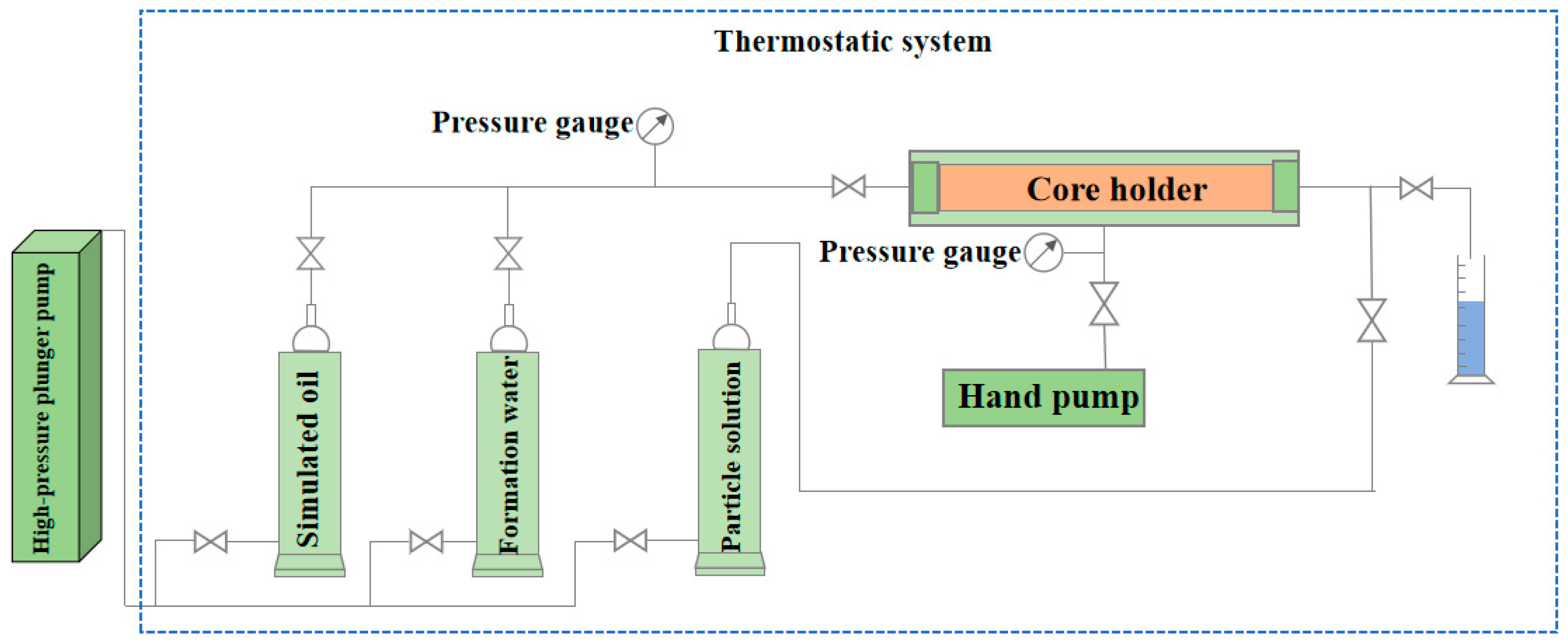
2.2.3. Core Flow Test

Core model production process: (1) Tools and materials: PVC tubing, acrylic sheets, oil well cement, a steel saw, and a handheld electric drill. (2) The acrylic plate was extracted from the PVC tube, and the model was divided into two parts. The core model was completely wrapped with a preservative film and heated in a 60 °C water bath for 24 h. After the model was cooled, two fractures with a fracture width of 2 mm were made by using a hand steel saw blade, and a 4 mm vug was drilled on the fracture by using a hand drill. Finally, a complete fracture-cavity core model was obtained.
Experimental method and process of the core flow test: (1) A fractured-vuggy core model with a length of 150 mm, a diameter of 25 mm, a fracture width of 2 mm, and a vug diameter of 4 mm was dried, vacuumed, and saturated with formation water. (2) A core flow test apparatus was assembled as per Figure 1, heated up to 130 °C, followed by oil drive to establish irreducible water saturation, and then held for 24 h. (3) For displacement, simulated formation water ran at a constant rate of 0.5 mL/min until the water content of the core was 98%. (4) Then, 1 PV of particle solution with a mass fraction of 10% was injected backward, and aged for a while at 130 °C, followed by forward water flooding again, during which various parameters were recorded.

3. Results and Discussion

3.1. Particle Screening and Coating Method

3.1.1. Batch Screening of Particles

For 27 types of swelling retarding particles, aging tests were conducted in simulated formation water at 130 °C for 1/3/5/10 days, mainly to study the swelling ratio, retarding swelling performance, long-term aging stability, and post-swelling properties (elasticity and hard brittleness) before screening. The detailed experimental data are in Table A2. In the preliminary screening, 24 types of swelling retarding particles were rejected because of (1) very high initial swelling ratios; (2) becoming firm in a short while at elevated temperatures; and (3) becoming brittle at elevated temperatures. Regarding the swelling capacities of the remaining three particles, as shown in Figure 2, XN-T remained resilient for 5 d and deformed under the action of kneading. The swelling rate began to stabilize after the 5th day, and the swelling rate decreased from 4.66 to 3.64 within 10 d. The water retention rate reached 72%. The water retention rates of ZB-4721 and ZB-4724 were only 22% and 19%, respectively, which indicates that the stability of XN-T under high temperatures is significantly better than the stability of the other two.

3.1.2. Preparation Method of Film-Coated XN-T

In previous experiments, we found that XN-T was still deficient in swelling retarding ability, which can seriously affect the injectability of the particles, so it was prepared as a coating.
As shown in Figure 3, XN-T are a type of three-dimensionally structured polymer polymerized from 2-acrylamido-2-methylpropanesulfonic acid (AMPS) and an acrylamide crosslinker. The AMPS monomer has a large molecular volume and is able to reduce the effects of Ca2+ and Mg2+ on the polymer backbone while effectively decelerating the hydrolysis reaction of the polymer at elevated temperatures, so as to enhance its heat resistance and salt tolerance. The coating solution was prepared with polyvinylidene chloride (PVDC), antioxidants (unsaturated sulfur oxides), and stabilizers (organic phosphonates). PVDC has the advantages of high toughness and strong chemical stability; it is a coating material for a reason. The mechanism of delaying swelling is that the hot film degrades slowly, forming micropores on the surface, and XN-T swells through contact with water. Under the swelling stress, the micropores turn gradually into cracks, and as XN-T particles swell up gradually, the swelling stress increases continuously, leading to film rupture.
Figure 4 shows the infrared spectrum of the film-coated XN-T. The peak at 3414 cm−1 is caused by the NH stretching of aromatic secondary amine; the peak at 1622 cm−1 corresponds to the angular vibration of primary amine NH2; the peak at 1099 cm−1 corresponds to the linear C–C stretching and CH3 rocking vibrations; the peak at 1099 cm−1 corresponds to the symmetric contractions of sulfonate SO3, which were caused by the of uncoated film XN-T itself. The peak at 788 cm−1 was caused by C-Cl of PVDC. Based on the above IR spectra analysis, the XN-T film was successful.

3.2. Evaluation of Film-Coated XN-T

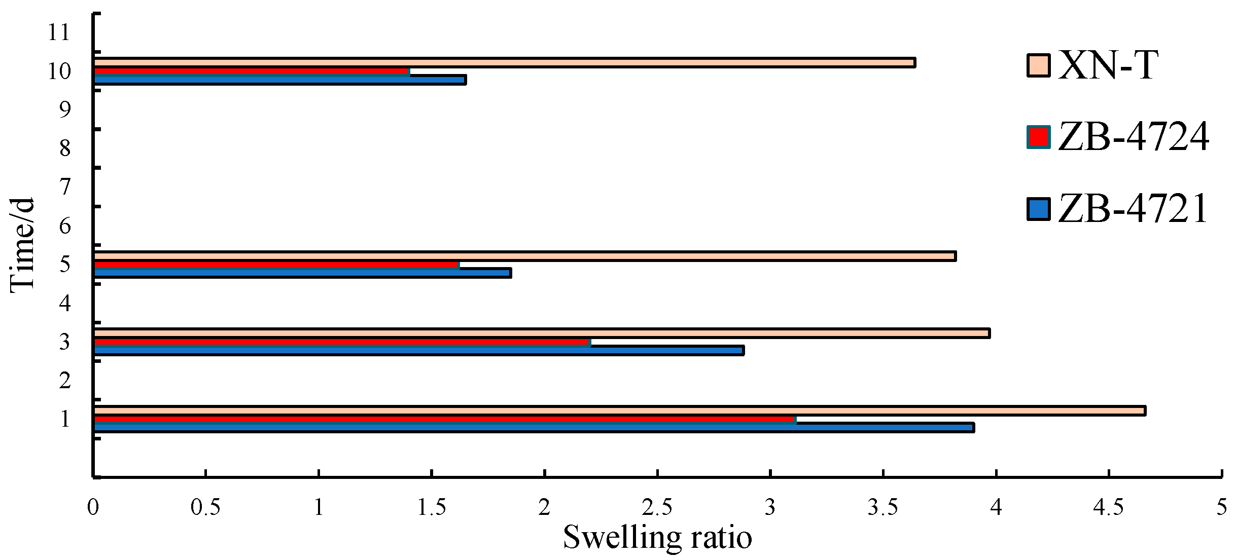
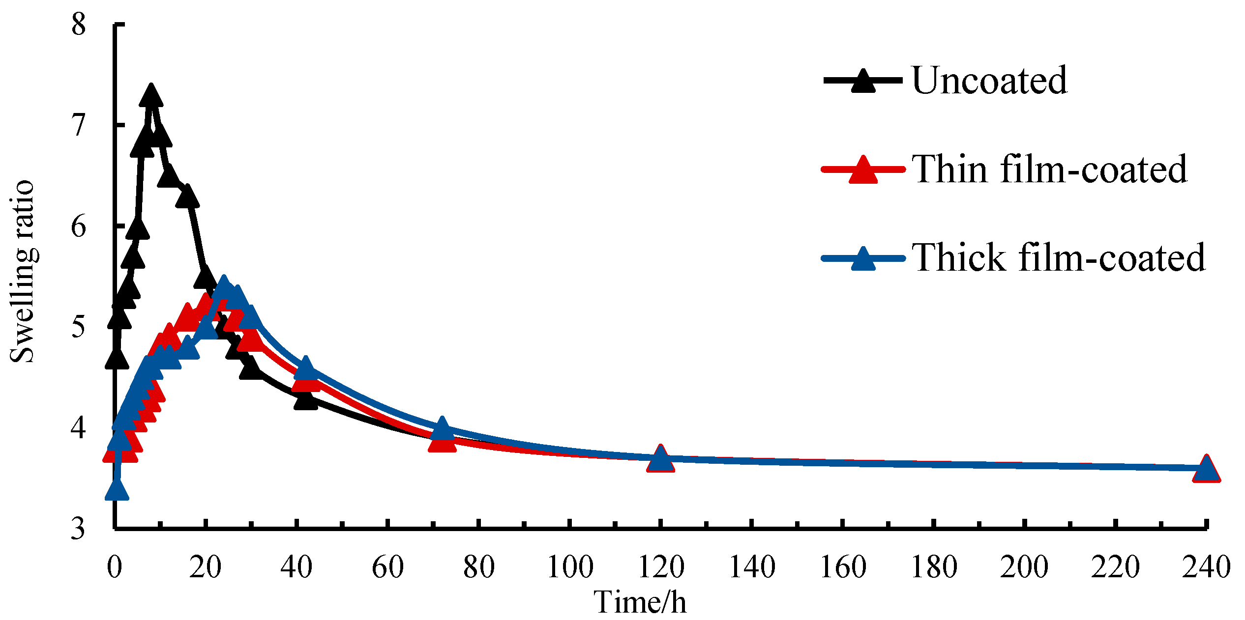
3.2.1. Evaluation of the Swelling Performance of Film-Coated XN-T

The swelling ratios of XN-T, thin film-coated XN-T, and thick film-coated XN-T at 130 °C were determined to study the retarding swelling performance and long-term aging stability of film-coated XN-T. Figure 5 shows that uncoated XN-T swelled rapidly in a short time, and the maximum swelling ratio (7.3) was achieved after 8 h. The maximum swelling ratios (5.3 and 5.4, respectively) of the thin film-coated XN-T and the thick film-coated XN-T were both achieved at 24 h, delaying the time to the maximum swelling ratio by 16 h. This shows that the film can effectively reduce the water absorption rate of particles, thereby slowing down the influence of salinity on particles. After the maximum swelling ratios were achieved, the film-coated XN-T began to shrink. Their swelling ratio tended to get stable after 72 h and became stable at around 3.6 by 240 h. Between 72 and 240 h, the three kinds of particles maintained the same swelling ratio and change trend, indicating that the existence of the film does not affect the swelling ability of the particles themselves—that is, the film is a physical process and does not affect the chemical properties of the particles themselves. The results demonstrate that the film-coated particles have a better retarding swelling performance. Since the particle properties of the two film thicknesses are basically the same, the thin film-coated XN-T was selected.
In order to understand more intuitively the reason why the thin film-coated XN-T has excellent swelling retarding ability and stability, we examined it via electron microscopy. As seen in Figure 6 (SEM images of the same non-water-saturated particles at different magnifications), the particles have a porous network structure for the purpose of strong water absorption, and the pores have rough internal surfaces and thick solid external surfaces such that the water-saturated particles have a very strong water-holding capacity. In addition, the walls between the internal pores are relatively thin. When water enters one of the pores, some of water can penetrate into the surrounding pores. These pores do not need to wait until the film breaks to be used passively. Therefore, the existence of the film largely inhibits the free swelling of particles. Thus, we can be more sure of the choice of the thin film-coated XN-T, because in the above experiments, the time taken to reach the peak swelling ratio was about 24 h for both thin film-coated XN-T and thick film-coated XN-T, indicating that the thin film can withstand the stress caused by particle swelling, and no further increase in film thickness is needed.

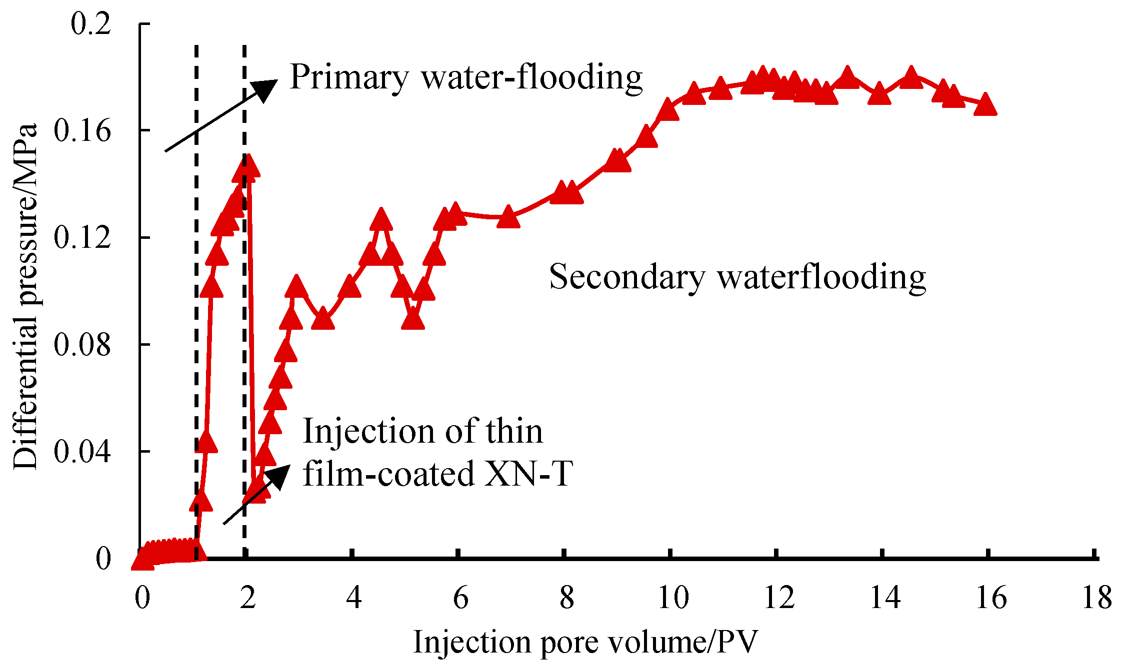
3.2.2. Evaluation of the Plugging Performance of the Thin Film-Coated XN-T

The self-made fracture-cavity core model was used for a core flow test. We calculated water-phase permeability (kw) prior to injection of the thin film-coated XN-T, and the post-plugging water-phase permeability (kw’) and plugging rate, so as to evaluate the profile control performance of the thin film-coated XN-T. As can be seen in Figure 7, in the first water flooding stage, the injection pressure was very small, and a great portion of water flowed along the fractures in the core model. The water phase permeability before the injection of the thin film-coated XN-T was calculated to be 78.82 mD. After reverse injection of 1PV into the thin film-coated XN-T, the particles swelled and established plugging, and the injection pressure rose sharply. At this time, the particles were mostly concentrated in the back half of the core. Then, after the second forward waterflooding, the pressure rose sharply. When the injection pressure was 0.102 or 0.127 MPa, respectively, the injection pressure decreased slightly, indicating that when the injection pressure was higher than this, the particles deformed and quickly passed through the cracks, entered the next cave and stayed at the crack entrance, and then established more stable plugging. The water phase permeability after plugging was 1.24 mD, and the water plugging rate was as high as 98.42%, indicating that the thin film-coated XN-T are capable of plugging fractures and vugs effectively.

3.3. Injection Parameter Optimization for Thin Film-Coated XN-T

Thin film-coated XN-T particles are very applicable to the profile control process for carbonate fractured oil reservoirs in the T oilfield due to high strength, good heat resistance and salinity tolerance, and excellent retarding of swelling. A physical flooding simulation test of a laboratory core was carried out to optimize particle injection parameters, so as to provide corresponding technical parameters for a subsequent field application.

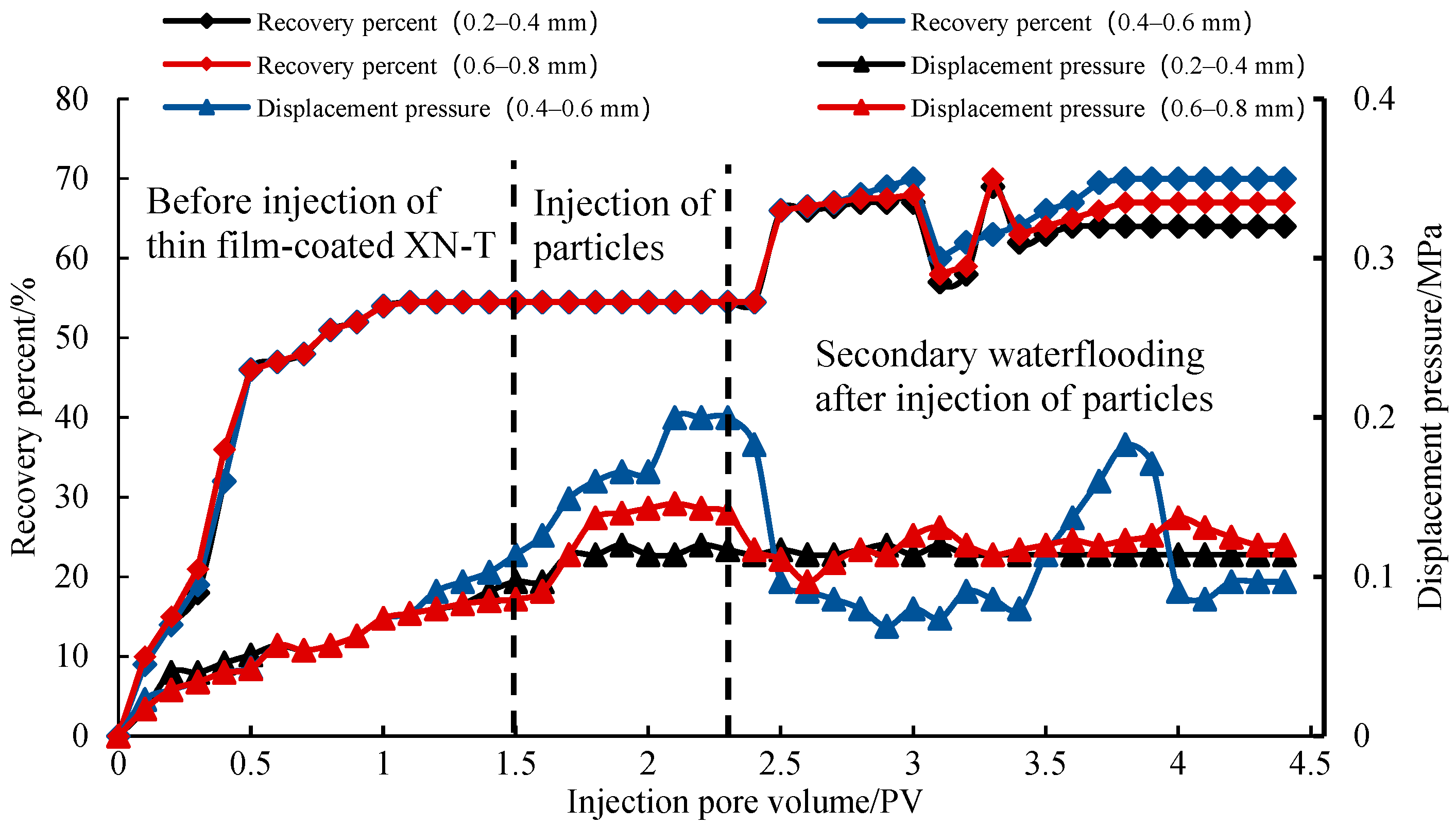
3.3.1. Optimization of the Thin Film-Coated XN-T by Particle Size

According to Bai’s research on the compatibility between swelling retarding particles and formation pore size, when the particle size is 1/5–1/2 of the formation pore size, it has the best compatibility [4]. Particles with an appropriate pore size will build up at fracture–vug junctures in the formation, resulting in tight blockage. Swelling retarding particles with too small a pore size will fail to build up to form stable blockages, and will be readily broken through by injected water and then discharged accordingly. Swelling retarding particles with too large a pore size would be prone to building up during injection, resulting in blockages that hamper the injection of more particles [14]. Since whether the size of the swelling particles matches the pore size of the formation directly affects the plugging effect, we designed particles with three ranges size, namely, 0.2–0.4 mm, 0.4–0.6 mm, and 0.6–0.8 mm, in order to study the effect of particle size on plugging effect. The test results are shown in Figure 8.
For the particles 0.2–0.4 mm in diameter, displacement pressure after particle injection was the lowest, i.e., 0.12 MPa, indicating a poor plugging effect, and the recovery proportion increased by 9.5% in subsequent waterflooding. For the particles 0.4–0.6 mm in diameter, displacement pressure was 0.2 MPa, tighter blockage could be established, and the recovery proportion increased by 15.5%. For the particles 0.6–0.8 mm in diameter, displacement pressure was 0.14 MPa, indicating a moderate plugging effect, and the recovery proportion increased by 12.5%. The plugging effect varied because the size of particles must match with the pore size of the formation. Considering plugging and recovery enhancement, the optimal particle size is 0.4–0.6 mm.

3.3.2. Optimization of the Thin Film-Coated XN-T by Mass Fraction

Particles with mass fractions of 7.5%, 10%, and 12.5%, respectively, were employed to study the effect of mass fraction on the plugging effect. As shown in Figure 9, for the particles with a mass fraction of 7.5%, the post-injection displacement pressure was the lowest, i.e., 0.16 MPa, indicating a poor plugging effect, and the recovery proportion increased by 14% in subsequent waterflooding. For the particles with a mass fraction of 10%, the displacement pressure was 0.2 MPa, and the recovery proportion increased by 16%. For the particles with a mass fraction of 12.5%, the displacement pressure was 0.31 MPa, indicating the best plugging effect, and the recovery proportion increased by 17%. As is known from the test results, within a certain range of particle mass fraction, the greater the particle mass fraction, the better the plugging effect and recovery enhancement, though the magnitude of recovery enhancement will decrease gradually, because the formation accommodates the particles to a limited extent. To guarantee a balance between recovery enhancement and cost, the optimal mass fraction of injected particles is 10%.

4. Summary

(1)
Based on the measured swelling ratios of 27 types of swelling retarding particles and corresponding experimental phenomena, XN-T particles were selected for physical film coating due to the best performance. The peak time of the thin film-coated XN-T swelling ratio was delayed by 16 h, and the plugging rate reached 98.42% in the core flow test, which is very suitable for fractured carbonate reservoirs. After optimization of injection parameters for the thin film-coated XN-T, the selected particle size was 0.4–0.6 mm, and the selected particle mass fraction was 10%.
(2)
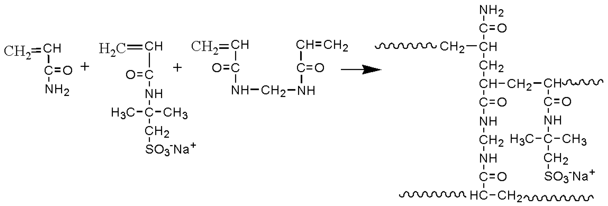
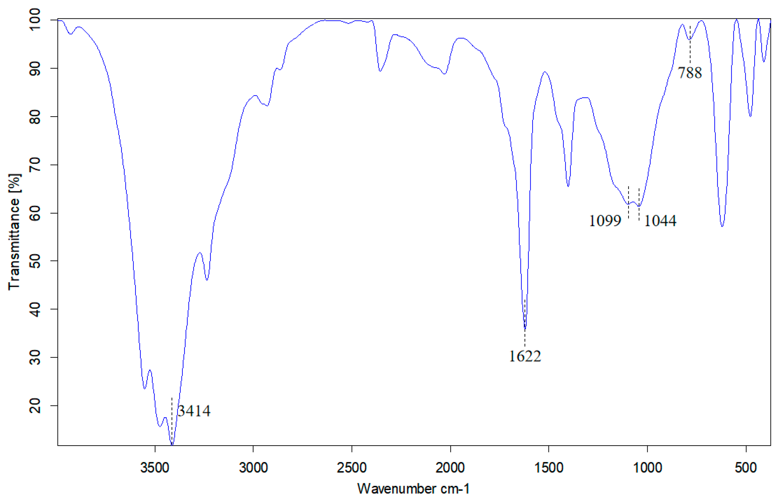
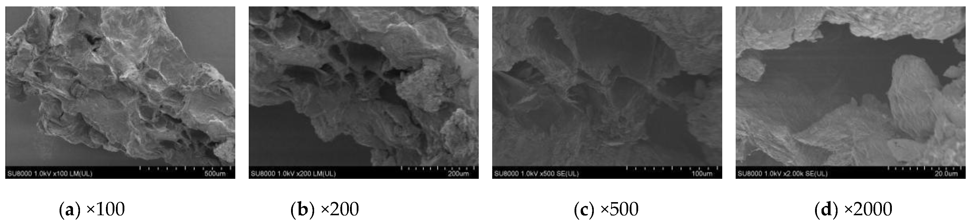
The thin film-coated XN-T, as a polymer, has a three-dimensional structure. The AMPS monomer provides the basis for its temperature and salt resistance; and the surface coating film improves the polymer’s swelling retarding ability, but not its own swelling ability and stability. It could be observed by SEM images that the surface has a porous network structure with thin walls between pores, which is conducive to water absorption, and the pores have rough internal surfaces and thick solid external surfaces, making the surface have strong water absorption and retention.
(3)
Swelling retarding particles have good effects on water control and oil proportion in fractured carbonate reservoirs, but there are few particles that can simultaneously adapt to profile control and water plugging of reservoirs under high-temperature and high-salt conditions. Due to the excellent performance of the thin film-coated retarded swelling XN-T, it will become an important option for oilfield recovery enhancement.

Author Contributions

Conceptualization, M.F. and G.L.; methodology, G.L., M.F. and X.L.; validation, G.L. and X.L.; formal analysis, G.L. and X.L.; investigation, G.L. and X.L.; resources, M.F.; data curation, G.L.; writing—original draft preparation, G.L.; writing—review and editing, G.L. and J.H.; visualization, G.L. and M.F.; supervision, M.F.; project administration, M.F.; funding acquisition, M.F. All authors have read and agreed to the published version of the manuscript.

Funding

This research was funded by the National Science and Technology Major Project, grant number 2016ZX05014-005-006. And The APC was funded by Meilong Fu.

Institutional Review Board Statement

Not applicable.

Informed Consent Statement

Not applicable.

Data Availability Statement

Informed consent was obtained from all subjects involved in the study.

Acknowledgments

This study was supported by the National Science and Technology Major Project “Study on Water Plugging Potential Evaluation Method and Selective Plugging Agent System for Fractured-Vuggy Carbonate Reservoirs” for the “The 13th Five-Year Plan” (grant number 2016ZX05014-005-006).

Conflicts of Interest

The authors declare no conflict of interest.

Nomenclature

Swswelling ratio in Equation (1)
m0particle mass prior to water absorption(g) in Equation (1)
m1particle mass after water absorption(g) in Equation (1)
PVpore volume
dday
hhour
Kwthe water-phase permeability
Kwthe post-plugging water-phase permeability

Appendix A

Table A1. A list of 27 kinds of swelling retarding particles.
IDCharacterIDCharacterIDCharacterIDCharacter
Z-1Coffee, Hard Z-4Block, White, Hard K-5Brown, SoftQZ-1White, Hard
Z-2Z-5K-6QZ-2
ZB-4721Block, Coffee, HardZN-1G-0Powdery, White, Hard JKBrown, Soft
ZB-4722K-1Transparent, Soft G-1JBTransparent, Soft
ZB-4723K-2G-2S-1Brown, Soft
ZB-4724K-3G-3XN-TBlock, Coffee, Hard
Z-3K-4J-1Khaki, Hard
Table A2. Aging tests of 27 kinds of swelling retarding particles.
IDSwelling RatioExperimental Phenomena
Temperature: 130 °C, Salinity: 22.4 × 10⁴ mg/L, Particle Quality: 2 g)
1 d3 d5 d10 d
QZ-230.640.920.860.80Swells rapidly, then begins to shrink sharply, and the particles harden after 1 day.
Z-12.532.172.061.90Initially soft, after 1 day, the particles shrink and harden, and no deformation occurs when squeezed by hand.
Z-221.771.651.40
Z-32.292.572.091.18The particles are always hard and do not deform when squeezed by hand.
Z-42.471.891.771.60After 1 day, the particles shrink and harden, and do not deform when squeezed by hand.
Z-52.841.861.621.42
ZN-12.861.952.311.20The particles are always hard and do not deform when squeezed by hand.
ZB-47223.122.241.781.50After 1 day, the particles shrink and harden, and do not deform when squeezed by hand.
ZB-47232.922.241.911.85
K-11.3111.051.02The particles are always hard and do not deform when squeezed by hand.
K-21.441.091.091
K-31.1110.980.85
K-41.611.371.111.04
K-51.411.361.441.21
K-61.371.130.960.88
G-01.982.031.991.74
G-11.911.781.891.42
G-21.061.891.81.65
G-31.421.691.81.63
J-11.391.251.811.55
JK0.830.80.850.79
JB0.980.920.860.82
S-11.211.040.930.85Initially soft, after 1 day, the particles shrink and harden, and no deformation occurs when squeezed by hand.
QZ-12.883.613.843.52After 1 day the particles are very brittle and will turn into powder when squeezed by hand.
ZB-47213.92.881.851.651 day, the particles are soft and will deform when pinched by hand; 3–5 days, the particles gradually become hard and will not deform when pinched by hand after 5 days.
ZB-47243.112.21.621.40
XN-T4.663.973.823.64

References

  1. Zhang, N.N.; He, D.F.; Sun, Y.P.; Li, H.W. Distribution characteristics of global large carbonate oil and gas fields and their controlling factors. China Pet. Explor. 2014, 19, 54–65. [Google Scholar] [CrossRef]
  2. Li, L.; Zhang, R.S.; Wu, Y.J.; Wu, J.W.; Liu, J.X. Mechanism of profile control by retarding swelling particles for fractured-vuggy reservoirs in the Tahe oilfield. Oilfield Chem. 2020, 37, 245–249. [Google Scholar] [CrossRef]
  3. Liu, D. Study on Comprehensive Management Techniques for Interim and Later Development of Oilfields. Ph.D. Thesis, Southwest Petroleum Institute, Chengdu, China, 2005. [Google Scholar]
  4. Bai, B.; Liu, Y.; Coste, J.P.; Li, L. Preformed particle gel for conformance control: Transport mechanism through porous media. Soc. Pet. Eng. 2007, 10, 176–184. [Google Scholar] [CrossRef] [Green Version]
  5. Li, D.X.; Hou, J.R.; Zhao, F.L.; Sun, L.; Wang, A.H. Study on the plugging performance of pre-crosslinked particles and the matching of particle size and porosity. J. Pet. Chem. Univ. 2010, 23, 25–28 + 33. [Google Scholar] [CrossRef]
  6. Bai, B.; Li, L.; Liu, Y.; Wang, Z.; Liu, H. preformed particle gel for conformance control: Factors affecting its properties and applications. Soc. Pet. Eng. 2007, 10, 415–422. [Google Scholar] [CrossRef] [Green Version]
  7. Jia, H.; Pu, W.F.; Zhao, J.Z.; Jin, F.Y. Research and application of water control and water shutoff method in fractured reservoir. Geol. Sci. Technol. Inf. 2010, 29, 62–70. [Google Scholar] [CrossRef]
  8. Yu, G.D.; Zhang, L.M.; Wang, D.Z.; Wang, P.H. Profile control agent for fractured low permeability sandstone reservoirs. Pet. Drill. Prod. Technol. 2004, 65–68, 85. [Google Scholar] [CrossRef]
  9. Tang, X.F.; Liu, Y.Z.; Yang, L.M.; Wei, F.L.; Ma, T.; Ma, H.W. Laboratory study of a high-strength retarding swelling in-depth fluid diversion agent. Pet. Explor. Dev. 2009, 36, 494–497. [Google Scholar] [CrossRef]
  10. Cui, G.D. Study on a Novel Type of High-Temperature-Resistant Retarding Swelling Particles. Master’s Thesis, China University of Petroleum (East China), Qingdao, China, 2016. [Google Scholar]
  11. Wang, Y.; Yao, B.; Lu, X.B.; Shen, X.L. Research and application of novel low-cost retarding swelling gel particles. J. Oil Gas Technol. 2014, 36, 204–207. [Google Scholar] [CrossRef]
  12. Pu, J.; Bai, B.; Alhuraishawy, A.; Schuman, T.; Chen, Y.; Sun, X. A novel re-crosslinkable preformed particle gel for conform-ance control in extreme heterogeneous reservoirs. In Proceedings of the SPE Annual Technical Conference and Exhibition, Dallas, TX, USA, 24–26 September 2018. [Google Scholar] [CrossRef]
  13. Bai, B.; Wei, M.; Liu, Y. Field and lab experience with a successful preformed particle gel conformance control technology. In Proceedings of the SPE Production and Operations Symposium, Oklahoma City, OK, USA, 23–26 March 2013. [Google Scholar] [CrossRef]
  14. Zhao, X.T.; Chen, Z.H.; Chen, W.X.; Ma, H.Q.; Zhai, D.Q.; Ren, Z.L. Research status and development trend of particle profile control water shutoff agent. Oil Drill. Prod. Technol. 2015, 37, 105–112. [Google Scholar] [CrossRef]
Figure 1. Particulated core flow test apparatus.
Energies 15 01085 g001
Figure 2. Comparison of three types of swelling retarding particles by swelling ratio.
Energies 15 01085 g002
Figure 3. The synthesis equation of XN-T.
Energies 15 01085 g003
Figure 4. The infrared spectrum of film-coated XN-T.
Energies 15 01085 g004
Figure 5. Swelling performance evaluation test of film-coated XN-T.
Energies 15 01085 g005
Figure 6. SEM images of the thin film-coated XN-T.
Energies 15 01085 g006
Figure 7. Profile control performance evaluation of the thin film-coated XN-T.
Energies 15 01085 g007
Figure 8. Displacement pressure curves and recovery percent curves for variable particle sizes.
Energies 15 01085 g008
Figure 9. Displacement pressure curves and recovery percent curves at variable particle mass fractions.
Energies 15 01085 g009
Publisher’s Note: MDPI stays neutral with regard to jurisdictional claims in published maps and institutional affiliations.

