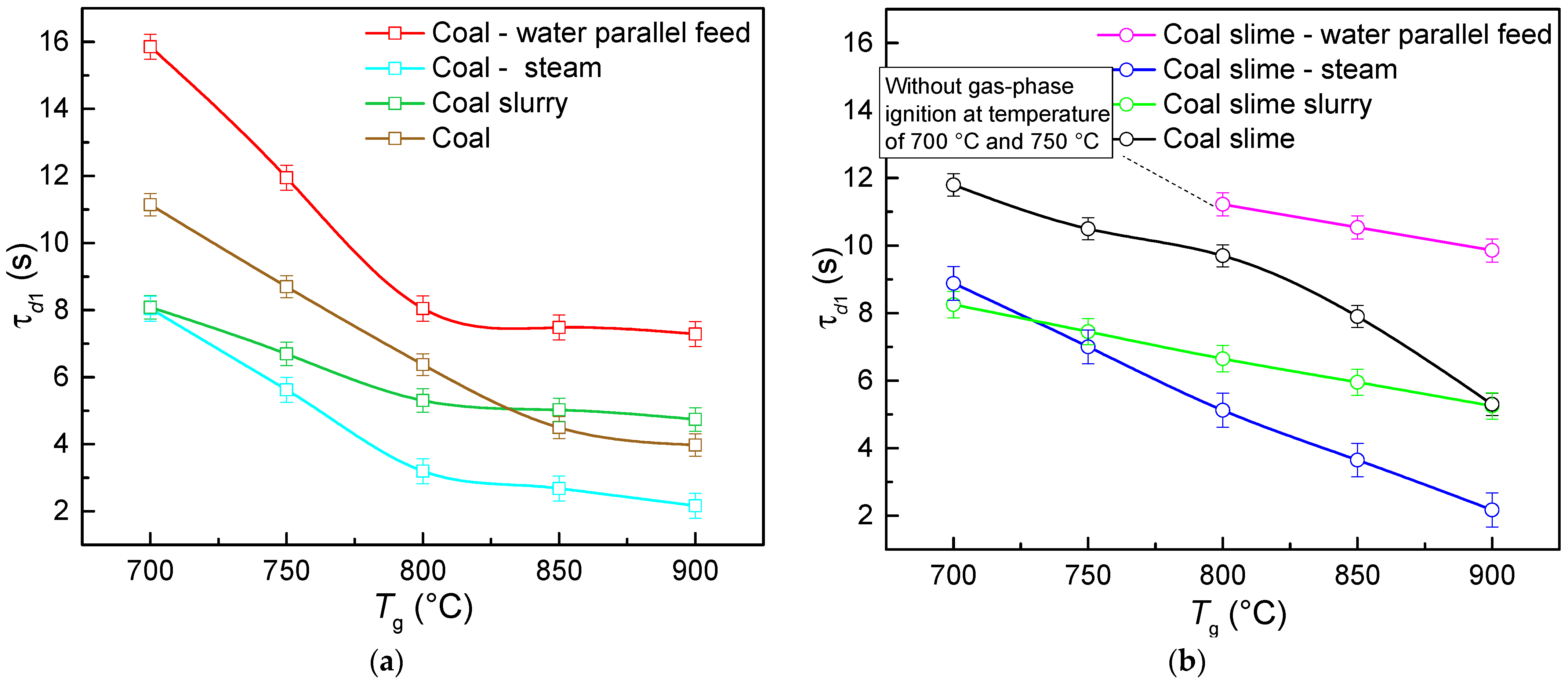
4.2. Ignition Characteristics
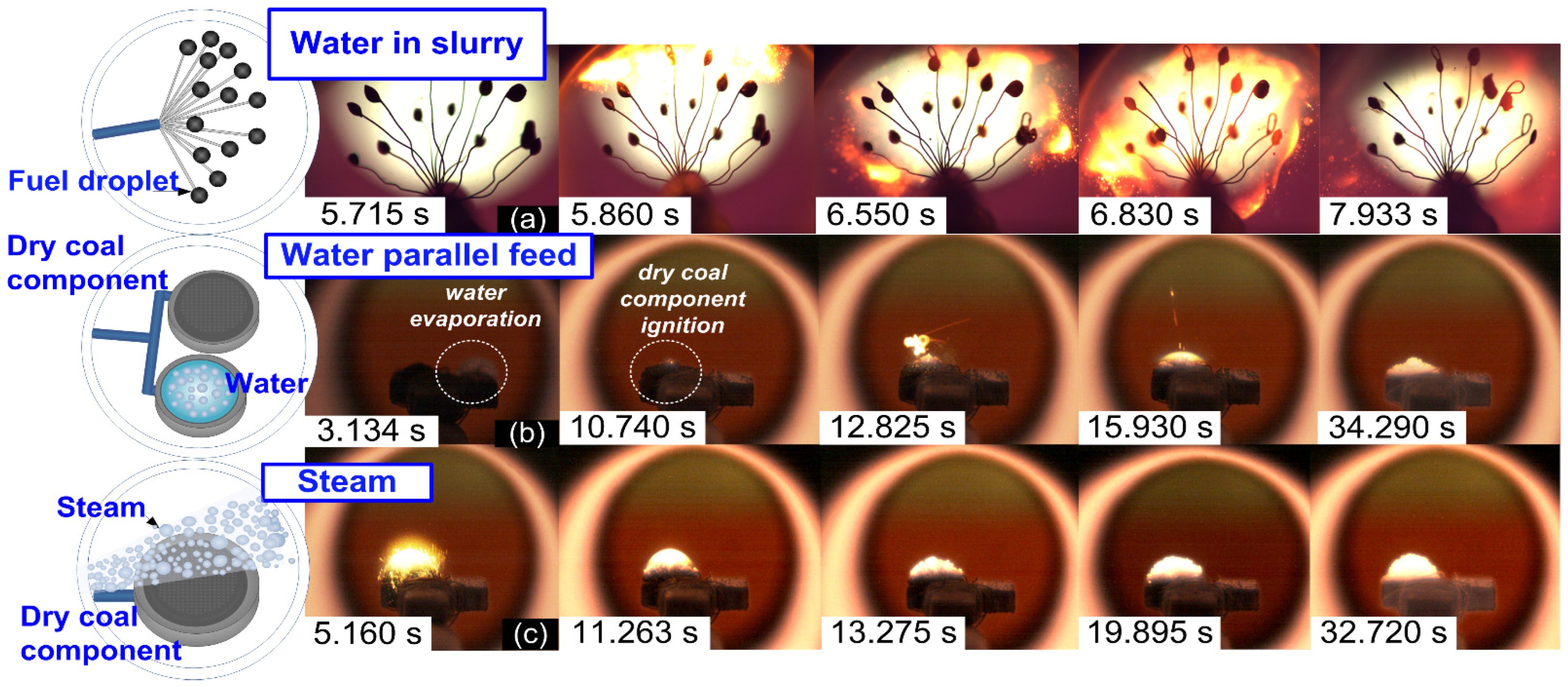
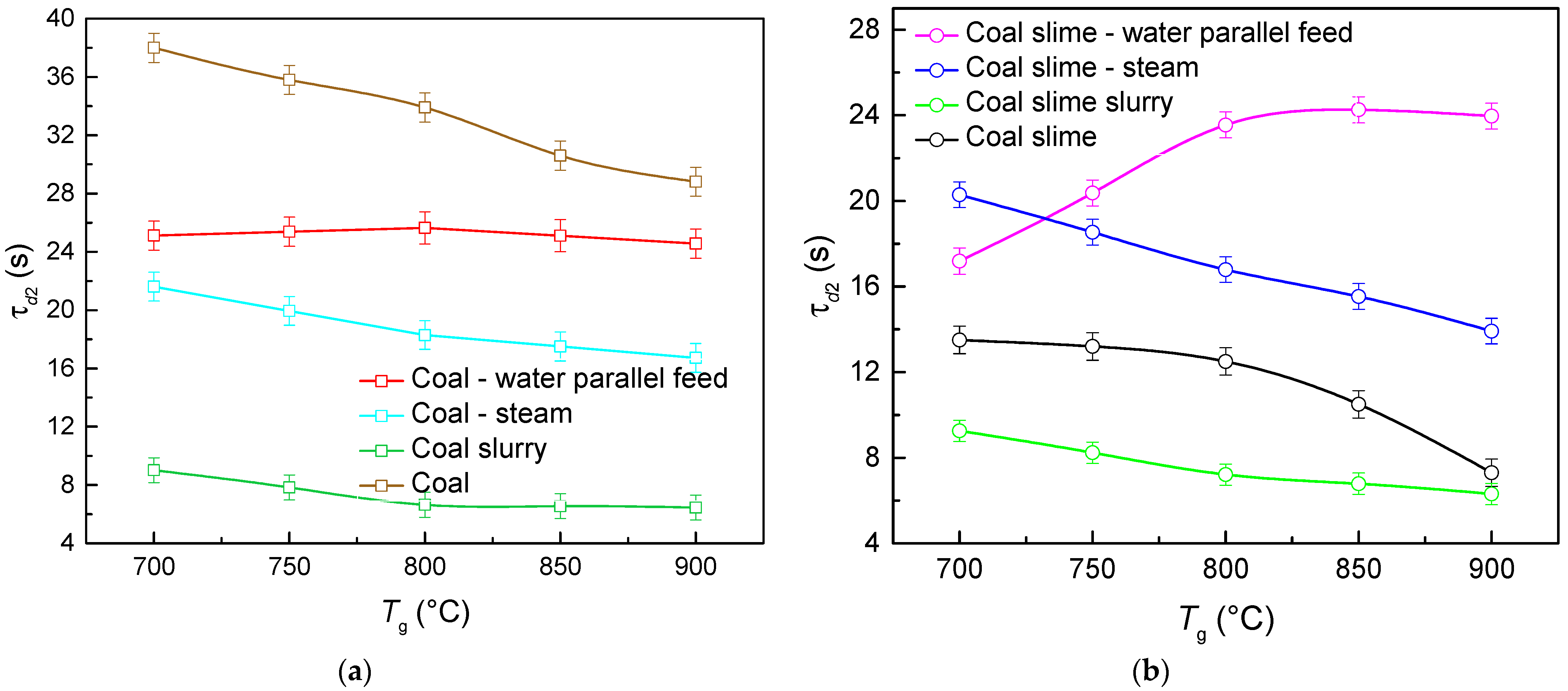
Figure 3 presents the curves for the gas-phase ignition delay time of the fuels under study versus the temperature in the combustion chamber. The highest ignition delay times were recorded when water was supplied in the form of droplets located in the close vicinity of the coal particles/slime piled on the substrate. This result is accounted for by the fact that quite a substantial amount of energy was spent on the heating and evaporation of liquid and the subsequent heating of vapors (whose specific heat capacity is twice as high as that of air). Therefore, the ignition delay in this method of supplying water to the combustion chamber becomes longer. Unlike in the case of a steam flow, the introduction of liquid droplets required extra energy for their heating and evaporation. When solid fuel particles were fed to the combustion chamber filled with steam, the ignition delay times were the lowest. Compared with the combustion of coal and slime in the air, the gas-phase ignition delay times decreased by 27–50% and 25–59%, respectively. This result illustrates that the high heat capacity and optical properties (absorption, transmission, reflection and the refraction of radiation) of the steam have a positive effect on the heating, pyrolysis and gas-phase ignition of volatiles. The energy accumulated in the thin water layer in the near-surface layer of the slurry droplet contributes to the quite significant local heating of the solid coal particles [
34]. The latter are pyrolyzed, and a gas–vapor mixture is formed in the thin near-surface layer close to the coal particles and the slurry droplet. This mixture has a high concentration of combustible gases and a rather high temperature at which gas-phase combustion occurs. This process increases the fuel surface temperature, enhances the volatile release and heats the solid framework that later ignites. Heterogeneous combustion takes place. Steam immensely absorbs radiation and accumulates the heat around the reacting fuel. This effect is crucial in this system. Steam injection into the combustion chamber somewhat reduces the gas medium temperature in the vicinity of fuel particles, but due to radiation absorption, the temperature quite quickly returns to the original values and then rises. When water slurry droplets are used, the fuel actively reacts at the initial stage in the thin near-surface layer. The video frames of the experiments revealed that the near-surface layers of the water slurry droplet are extensively heated when they are introduced into the combustion chamber; the gas-phase combustion begins, followed by heterogeneous combustion.
The conducted experiments showed that when water droplets were fed in simultaneously alongside a pile of coal slime particles, the gas-phase combustion stage in the temperature range of 700–800 °C was not very pronounced. The gas-phase combustion became more active with the increase in the temperature in the furnace to 800 °C (
Figure 3b). Extensive gas-phase combustion was not recorded even at lower temperatures in the chamber. In the thin near-surface layer, weak luminance was recorded, indicating the gas-phase combustion of the products of thermal decomposition of the carbon-containing solid particles. The recording of the conditions of the marked gas-phase combustion of pyrolysis products at relatively low temperatures in the chamber was complicated by extensive vaporization. The steam reduced the temperature of the gas–vapor mixture. Another important factor was the limited content of volatiles in coal slime (
Table 1).
At high temperatures in the chamber, e.g., at 800 °C, the flame combustion of a slime layer was sustainably recorded, yet it took 13–46% more time for the gas–vapor mixture to achieve it than in the combustion of coal slime of the same mass in the air (
Figure 3b).
Introducing slurry fuel droplets into the combustion chamber was characterized by the average ignition delay times of the fuel samples under study. This is explained by the fact that the gas-phase ignition of the slurry fuel is only possible after the moisture preventing the release of volatiles from the fuel surface evaporates from the near-surface layer. In turn, using steam enhanced the fuel ignition without any extra heat lost upon evaporation.
It was also established that with all the fuel-feeding schemes under consideration, using bituminous coal leads to a lower ignition delay time than when coal slime is used. This is accounted for by the fact that bituminous coal contains more volatiles (
Table 1) whose gas-phase combustion contributes to a significant increase in the temperature of the coke residue and thus in the rates of its heterogeneous combustion.
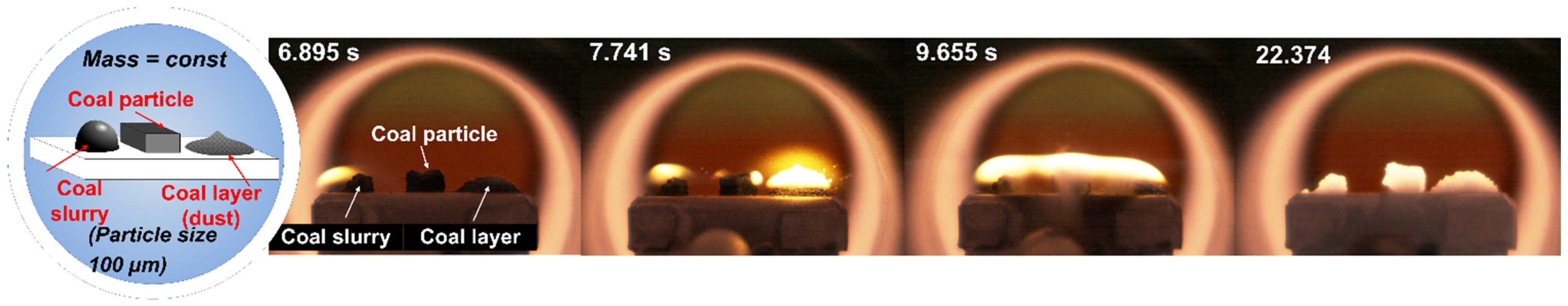
To justify the comparison of the integral characteristics of the ignition and combustion of a group of slurry droplets and a thin layer of coal particles spread on a substrate, additional experiments were conducted. The results are shown in
Figure 4. When a slurry droplet, a coal powder pile and a single large coal particle, all of an identical size, were ignited, the gas-phase ignition of the slurry occurred sooner than that of the coal samples. The solid coal particle ignited later than the other fuel samples. This is because the particle size of coal powder in a pile and of the slurry was smaller than that of the single coal particle. The gas-phase reaction of the slurry droplet and coal pile with solid particles of the same size was characterized by almost identical ignition delay times. This result demonstrates the decisive role of the size of solid particles in the composition of the pile and slurry. The finer the solid particles, the weaker the effect of water on the time lag in the heating of the near-surface layer of slurry droplets. Their heating time until they ignite is the same as that of the samples of identical particles that were not additionally wetted. These specific aspects have a significant effect on the subsequent heterogeneous reaction of the coke residue.
Figure 5a presents the experimentally obtained curves of the heterogeneous ignition delay times of the fuels based on coal versus the temperature in the furnace. Bituminous coal dust reacting in the air medium has the highest delay times of heterogeneous ignition. Creating a steam-air environment when introducing separate water droplets on the substrate or when supplying steam makes it possible to reduce the heterogeneous ignition delay times of the coke residue of coal by 14–33% and 46–52%, respectively. Although the gas-phase ignition of coal (
Figure 3a) occurred more slowly when it was in parallel with the water supply, the heterogeneous ignition was recorded sooner than for the reactions of coal particles without water droplets around them. The temperature conductivity of water vapors is lower than that of the air. Consequently, the heat released from the combustion of volatiles in the presence of water vapors spreads more slowly throughout the combustion chamber volume and is concentrated on the surface of coal particles. The coke residue ignition proceeded faster. Similar effects were observed in [
21]. The effect of the steam environment on the characteristics of pulverized coal combustion in the O
2/CO
2 atmosphere was explored. The presence of water vapors was shown to lead to faster burnout and increase the overall reactivity of coal. The diffusion rate of O
2 in the atmosphere of steam is claimed [
21] to be much higher, which is responsible for the reaction intensification.
In the case of coal slime (
Figure 5b), the specified effect of the rapid reaction of the near-surface layer of droplets led to the agglomeration of particles on the fuel surface and the formation of a coke envelope that slowed down the release of volatiles and their mixing with oxygen. Thus, the gas-phase combustion rates slightly decreased. This increased the heterogeneous ignition delay times of coal slime when it was heated in the steam environment (as compared with the combustion of coal in a steam environment). The heterogeneous ignition of coal slime in the air started 21–69% faster. When a coal slime sample was fed in simultaneously with water droplets, there was an increase in the heterogeneous ignition delay time with a temperature rise from 700 to 800 °C. This is caused by the fact that, at combustion chamber temperatures lower than 800 °C, no extensive gas-phase combustion of pyrolysis products or evaporation of components of this fuel was recorded. Irrespective of the type of the coal component, the combustion of solid fuel particles in the slurry droplet composition was characterized by the shortest gas-phase combustion (the process developed actively), which, in turn, led to low heterogeneous ignition delay times. The transition from gas-phase combustion to heterogeneous combustion occurred faster due to the heating of the thin near-surface layer. The heterogeneous ignition delay times of slurry droplets were 1.5–4 times lower than those of the other combustion schemes under study.
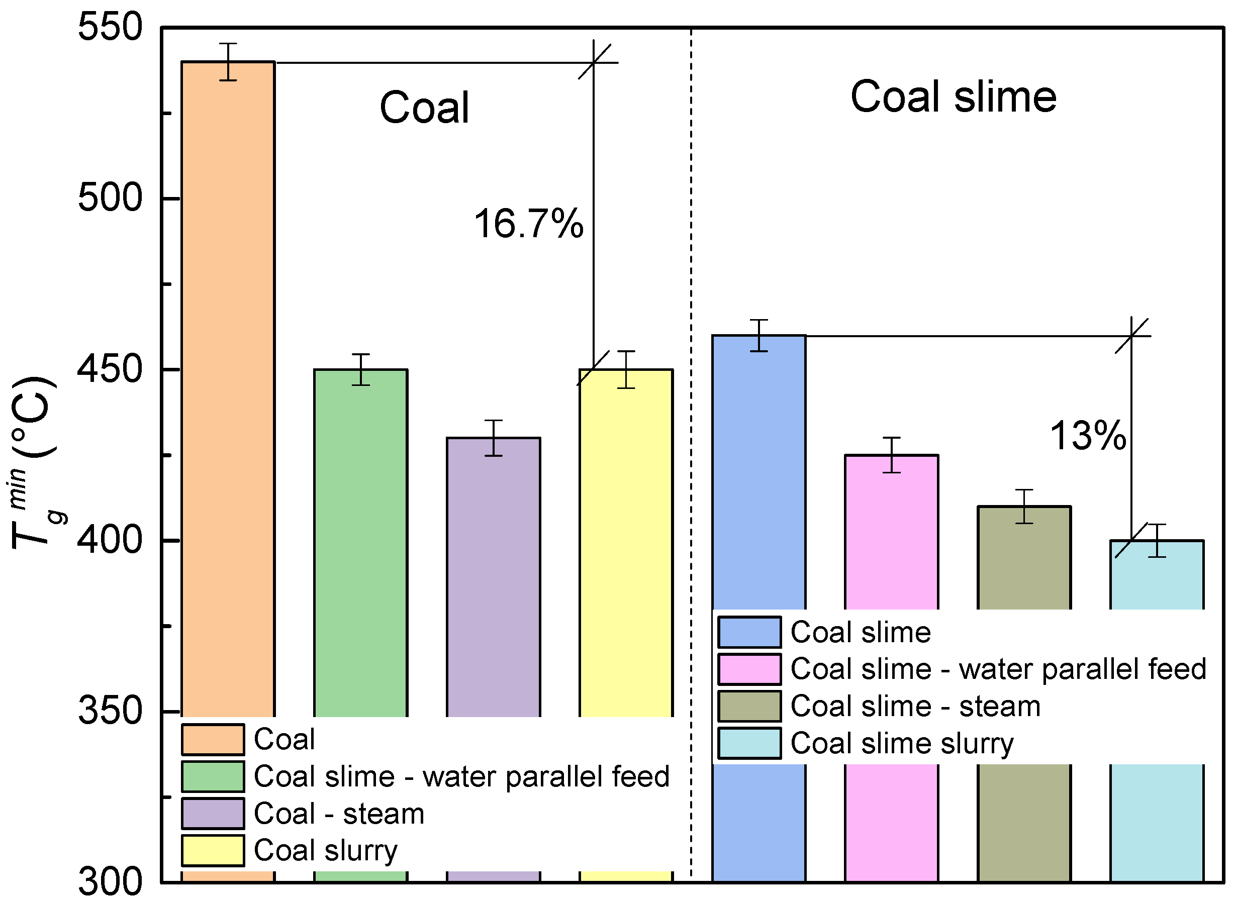
Figure 6 illustrates the lowest ignition temperatures of the fuels, determined experimentally for the combustion schemes under consideration.
Tgmin is the minimum temperature in the furnace at which the steady heterogeneous combustion of solid fuel particles occurs. The highest
Tgmin was recorded for the samples of coal and slime reacting in the air. The ignition of coal components in the steam-air environment, on the contrary, occurred at lower temperatures. Thus,
Tgmin for the coal–water suspension decreased by 16.7% in comparison with the dry coal combustion. The lowest ignition temperature was recorded in the experiments with a mixture of coal slime with water in a slurry composition. This result is likely to be conditioned by the specific aspects of liquid evaporation from the surface of the slurry fuel droplets. The water in the composition of the slurry based on coal slime evaporated faster than in the slurry based on bituminous coal due to the higher density and viscosity affected by the flocculants used for coal preparation. An increase in the concentration of vapors in the close vicinity of the sample facilitated its heating due to radiant heat exchange. Therefore, to reduce the ignition temperature of coal fuels, it is advisable to use a water-steam-saturated atmosphere.
4.3. Combustion Characteristics
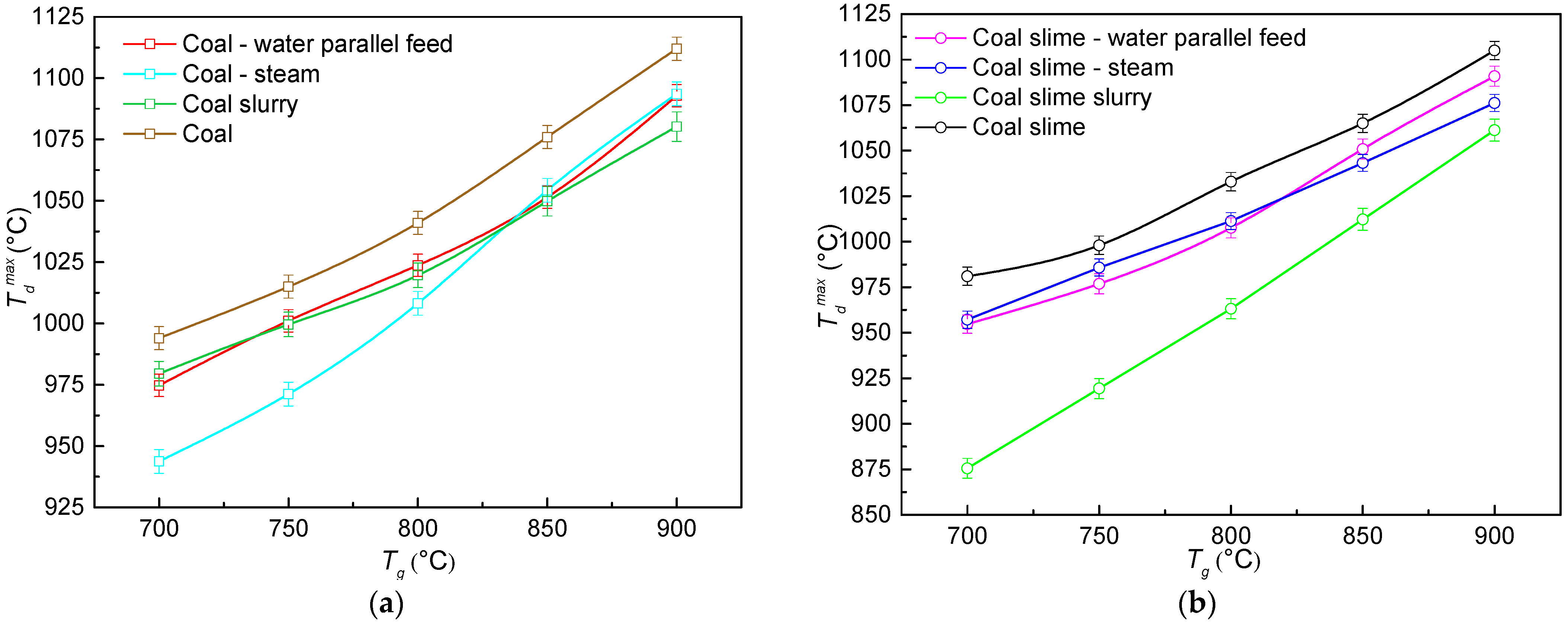
Figure 7 presents the curves of the maximum combustion temperatures of the coke residue, obtained in the conducted experiments when varying the temperature in the combustion chamber. The recorded values of this parameter corresponded to the range of 875–1112 °C. The lowest maximum combustion temperature within the range under study is typical of the fuel slurry based on coal slime. This result might be related to the fact that combustion was more uniform when a slurry was used. In turn, with the simultaneous introduction of the components and the steam-air atmosphere in the combustion chamber, the temperatures in the fuel combustion zone increased and became comparable with those of the fuels reacting in the air medium. This is explained by the fact that rapid vaporization increased the diffusion rate of oxygen in the combustion zone and, thus, the rate of the interaction of carbon with vapor:
This interaction results in additional combustible gases. Their interaction with oxygen releases extra thermal energy, thus increasing the temperature in the reaction zone. A similar conclusion was drawn in [
21]. It was established that during the combustion of three types of coals in the atmosphere with steam, the maximum temperatures of the combustion of samples increased by 5–10 °C. This result is explained by a higher rate of oxygen diffusion to the coal particles in the presence of water vapors. Moreover, the research showed that the maximum combustion rates and average mass-loss rates during the combustion of coal were significantly higher in the atmosphere with water vapors than in the N
2 atmosphere. However, despite the differences, the discrepancy between the maximum combustion temperatures in this research and those in [
21] did not exceed 5%. This is conditioned by the fact that the main fuel component was the same (coal and coal slime). Its characteristics determine the maximum temperature of the heterogeneous combustion of carbon to a greater degree than the external gas-vapor medium does.
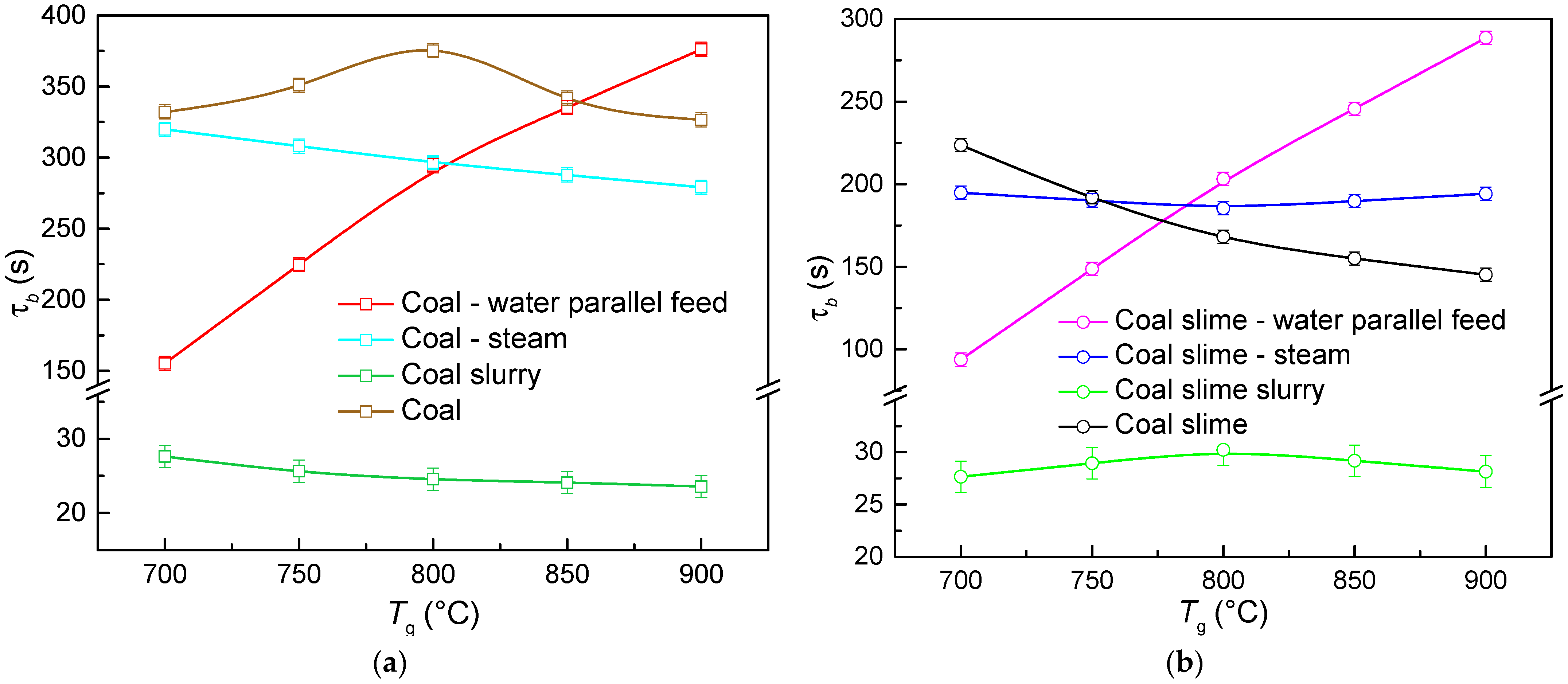
The curves for the duration of the fuel combustion versus the temperature in the combustion chamber are presented in
Figure 8. The obtained curves look significantly different for the three schemes of solid fuel combustion under the conditions of increased moisture in the furnace chamber. In the case of the parallel introduction of water droplets and solid fuel particles, the combustion duration of coal components increased with a temperature rise. This trend indicates that at lower temperatures, the combustion stopped before all the combustible parts of the fuel reacted. Substantial energy was spent on the evaporation of water droplets located near the solid fuel particles on the substrate. In addition, the specific heat capacity of the resulting water vapors is higher than that of the air. Therefore, a considerable amount of energy is required to heat them. Thus, a certain amount of energy was removed from the surface of the fuel, and it stopped burning faster in the areas of low temperatures. In this case, the fullest involvement of the combustible mass in the burnout is only possible by increasing the amount of heat supplied to the fuel sample.
In the case of combustion in a water-steam-saturated atmosphere, the duration of the fuel combustion decreased as the temperature in the muffle furnace went up. The supply of generated steam increased the reactivity of the fuel and promoted its more complete burnout compared to the simultaneous introduction of components [
21].
The lowest combustion time was typical of slurry fuel droplets based on coal slime and bituminous coal. This effect is conditioned by the fact that the burned fuel mass is separated into a group of small droplets, which provided a free supply of oxygen to the combustion zone. Another important factor is that uniform combustion over the fuel surface weakened the effect of the resulting ash barrier during the release of volatiles from the deep layers of the fuel sample, i.e., the ash crust on the particle surface clogged some of its porous channels and did not allow the release of all the volatiles for the gas-phase burnout. The coke formation on the particle surface slightly suppressed the heterogeneous combustion of carbon.
The comparison of the two types of coal components reveals that the combustion duration of coal samples (except for slurry droplets) is higher than that of coal slime. This result is related to the fuel characteristics. Coal slime is a high-ash waste with quite a low content of combustible mass. Consequently, it takes less time for it to burn out completely. It is possible to assume that the steam-air environment intensified the interaction of the oxidizer with the coke residue of the slime, thus leading to the growth of its combustion rate. At temperatures exceeding 750 °C in the combustion chamber, the duration of coal slime combustion in the steam environment increased by 9–25% compared to the same characteristics of the reaction of slime particles in the air. The steam intensified the diffusion transfer of oxygen to the inner layers of the fuel. During coal slime combustion at high temperatures, it slowed down due to the gradual formation of a dense ash envelope. A similar finding was obtained in the study [
26], which analyzed the effect of steam on the combustion characteristics of pulverized coal using a thermogravimetric analyzer during oxy-fuel combustion. A decrease in the burnout time and an increase in the mass-loss rate (by up to 35%) were observed after steam was added to the combustion atmosphere.
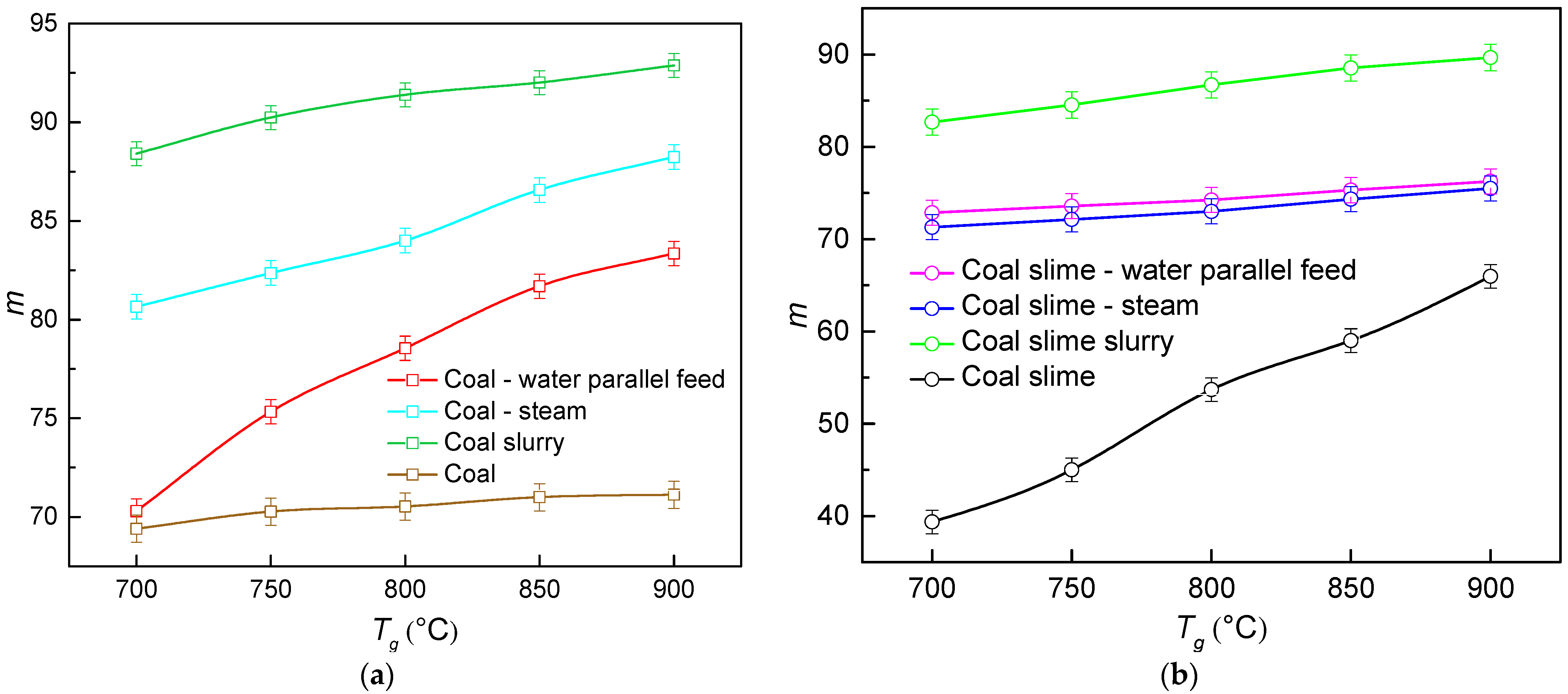
Figure 9 presents the curves of the relative indicator of the fuel burnout versus the temperature in the combustion chamber, given by:
where m
0 is the initial sample mass, and m
1 is the mass of the unburnt char.
In line with Equation (1), the greater the value of m, the more complete the fuel burnout. The obtained relative indicators of burnout (
Figure 9) are quite consistent with the data on the effects of the temperature in the furnace on the fuel combustion time (
Figure 8). The experiments showed that, with the parallel supply of coal and water, the mass-loss rate (
Figure 9a) was lower compared to direct steam injection. At lower temperatures, the combustion of coal with nearby water droplets stopped before the entire combustible part of the fuel had time to react (due to the loss of energy for the evaporation of water). So, at a temperature of 700 °C, the mass of the unburned part (m
1) was commensurate with the mass remaining during the combustion of coal in air. The increase in temperature intensified the burnout of coal with the parallel supply of the components. The direct steam supply was characterized by higher values of the relative burnout index, which ranged from 81 to 88%. This result indicates an intensification of oxidant diffusion and carbon gasification in the vapor environment, which improved fuel burnout.
When burning coal slime (
Figure 9b), no noticeable differences in the burnout characteristics were recorded when water and slime were supplied separately, or when steam was used. The difference between the corresponding coefficients did not exceed 2%. The characteristics of the coal slime, in particular the high ash content and the presence of flocculants, had a greater effect on the burnout rate. Although steam intensified the diffusion transfer of oxygen to the inner layers of the fuel, at high temperatures this process slowed down due to the gradual agglomeration of ash particles in the pores.
The maximum burnout rate was recorded during the reactions of slurry fuels based on coal slime and bituminous coal. As with the combustion duration, this effect is conditioned by the even heating and burnout of fuel droplets. Compared with coal and coal slime reacting in the air, the burnout indicator of slurry fuels increased by 21–23 and 26–52%, respectively. In general, the comparison of the two coal components indicates that the burnout indicator of coal is up to 15% higher than that of coal slime due to the high ash content of the latter (
Table 1). One important finding is that the formation of a steam-air environment due to the evaporation of nearby water droplets or steam injection makes it possible to increase the degree of carbon burnout by up to 46%. This effect is more pronounced for coal slime (especially in the low-temperature range).
Table 2 presents the experimental research findings for the effect of steam content on the temporal characteristics of the ignition and combustion of coal powder at a temperature of 800 °C in the combustion chamber. An increase in the steam content was shown to lead to higher delay times of gas-phase and heterogeneous ignition. It took more time to heat the created steam-air environment. However, the opposite effect is produced by an increase in the steam content throughout the duration of coal combustion. The duration of the sample combustion decreased by 10% with a twofold increase in the steam content. The result is attributed to the fact that the steam-air environment intensified the interaction of the oxidizer with the coke residue and enhanced the heat transfer to the deep fuel layers.
4.4. Environmental Characteristics of Combustion
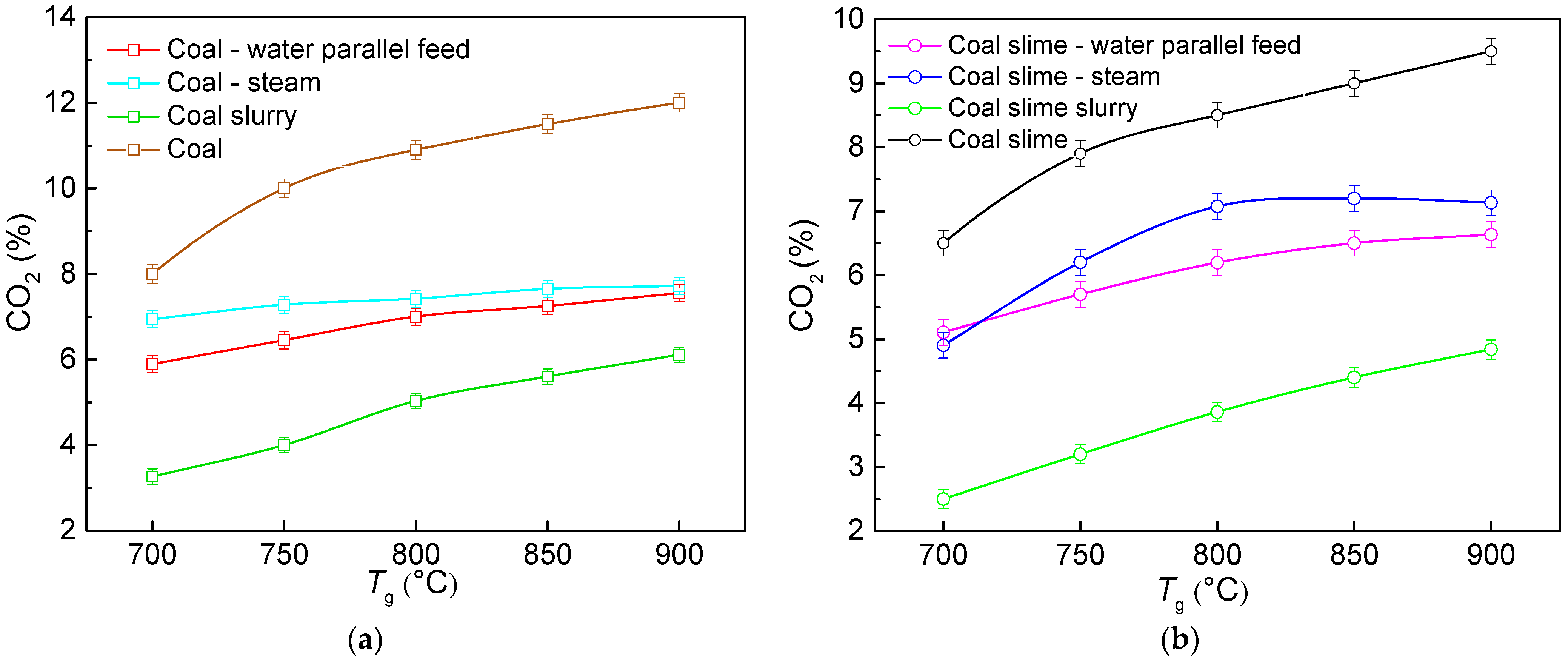
Figure 10 presents the curves of the average concentrations of carbon dioxide plotted for the examined schemes of fuel combustion. The comparison of CO
2 concentrations released from the combustion of coal and coal slime in the air revealed that using water (as a separate component, steam or in the slurry composition) makes it possible to reduce CO
2 emissions from 20 to 61%. This effect is accounted for by a decrease in the temperature in the combustion zone. Compared with slurries, the steam contributed to higher concentrations of carbon dioxide. The presence of steam increased the duration of the gas-phase combustion with a proceeding reaction [
35,
36,
37]:
The subsequent oxidation of hydrogen resulted in OH hydroxyl, H and O atoms. The presence of active hydroxyl centers and atomic hydrogen in the flame zone intensified the reactions of oxidation and combustion of the hydrocarbon fuel. Additional trajectories of hydroxyl radical formation are given by [
38]
The reactions (4) and (5) proceed in a rather wide temperature range from 20 to 2200 °C [
39], yet with a temperature increase, the constants of the rates of these reactions significantly increase. Thus, with the temperature increasing from 500 to 700 °C, the rate constants increased up to 12 times, and with an increase from 700 to 900 °C, by up to 5.5 times. This indicates that, in the temperature range under consideration, the reactions are expected to proceed steadily [
39].
Thus, the catalytic effect of steam on the combustion of carbon monoxide (CO) is related to the reaction (6), resulting in an increase in the carbon dioxide concentrations [
39]:
Like the reactions (4) and (5), the reaction (6) proceeds in the temperature range from 20 to 2200 °C [
39], yet at 700 °C, the rate constant changed by no more than 10% with a temperature rise by every 100 °C (in the temperature range from 20 to 600 °C, the difference in the rate constants when varying the temperature by 100 °C was 12–16%) [
39]. Moreover, a temperature rise increased the fuel combustion rate and intensified the release of volatiles from the fuel, which led to lower oxygen concentrations near the surface of the burning particles. Thus, the CO concentrations in the flame front increased (reaction R1). As a result, the interaction of steam with carbon (reaction (1)) and CO (reaction (3)) intensified towards the formation of CO
2.
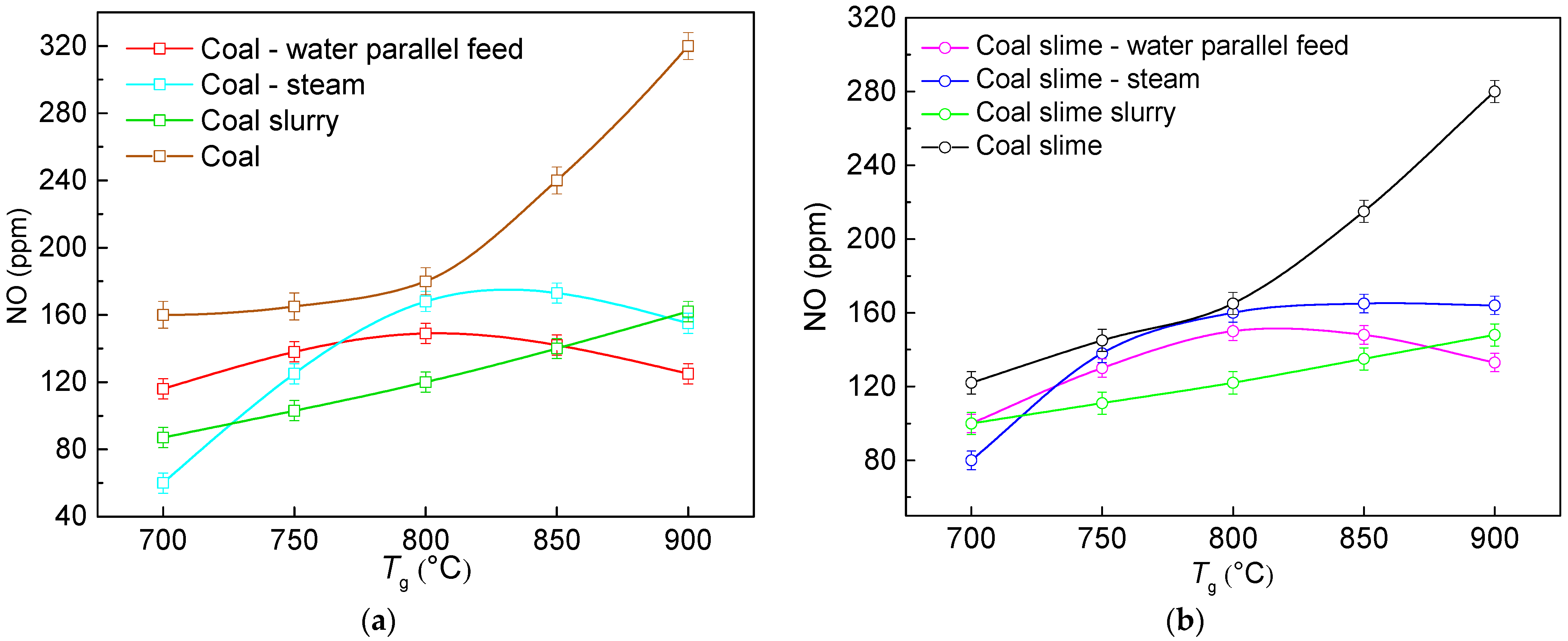
The analysis of the results (
Figure 11) suggests that introducing water into the combustion chamber significantly reduces the NO emissions (by up to 2.7 times). This effect became especially noticeable at temperatures above 800 °C. The evaporation of water with a relatively high molar heat capacity and absorbing heat and the low partial pressure of oxygen produce a combined effect. This reduces the combustion temperature and hence slows down the formation of nitrogen oxides. The plotted curves are consistent with the research findings in [
22], which studied the combustion and pollutants of water-emulsified fuel. An increase in water content was shown [
22] to reduce the NO
x concentrations by up to 70%. The latter was explained by a temperature decrease (of up to 17%) in the combustion chamber, in particular, due to a reduction in the peak flame temperature during combustion. Moreover, it was assumed that the presence of water increased the amount of OH radicals that reacted with excess oxygen and caused the reduction of NO
x [
22].
The shapes of the curves of nitrogen oxide concentrations versus the temperature in the chamber with the simultaneous introduction of water, in the form of steam, and the coal component were rather surprising (
Figure 11). In the temperature range from 700 to 800 °C, the concentrations increased and reached peak values at 800 °C. A further increase in the temperature to 900 °C was characterized by a steady decrease in NO concentrations to values close to those for the slurry combustion. It was established that the creation of a steam environment during the combustion of coal fuel intensified the release of volatiles and increased the reactivity of the fuel due to the heat released from their combustion. Moreover, the gasification of char with steam increased the porosity of its particles, thus contributing to the diffusion of oxygen into the deep fuel layers. This resulted in a higher burnout degree and a greater amount of nitrogen reacting in the combustion, which caused NO to increase [
40] in the temperate range between 700 and 800 °C. Similar effects were discussed in [
20]. Wang et al. [
20] investigated the effect of a steam environment on the characteristics of the isothermal combustion of coal in a thermogravimetric experimental system. The content of the steam varied, in the range of 10–30%. Wang et al. [
20] established that, with an increase in the steam concentration, the TG curves shifted towards lower times, which indicated an increased mass-loss rate of char and a decreased burnout time. The authors explained this result by the fact that the gasification of coal with steam could occur at a low oxygen concentration, which increased the porosity of coal particles.
However, at a higher temperature (900 °C), the steam molecules could react with coal particles and CO to produce active hydrogen (H) atoms and active hydroxyl (OH) radicals which participated in the reactions of NO reduction with the help of NH
i [
41,
42]:
For the reactions (7)–(9), at temperatures above 900 °C, constants reach certain values, and with a temperature increase of 100 °C, the difference between the constants does not exceed 10% [
39,
43,
44]. This suggests that at temperatures above 900 °C, the above reactions can proceed sustainably.
It was established that in the temperature range of 725–850 °C, the lowest concentrations of nitrogen oxides were recorded during the combustion of slurry droplets. For all the schemes of introducing coal component samples and water into the combustion chamber, the shapes of the curves obtained during the combustion of coal and coal slime correlate favorably with each other. The difference in nitrogen oxide concentrations was recorded. In general, they were 20% higher for coal than for coal slime. This effect is explained by the different content of fuel nitrogen (
Table 1) which is 5% higher for coal (accounting for the ash content of the components) [
41]. As the ash content of coal slime is up to 1.5 times as high, the combustible part of the fuel (made up primarily of the fuel nitrogen) is lower. As a result, NO concentrations in the decomposition and oxidation stage during coal slime combustion are lower.
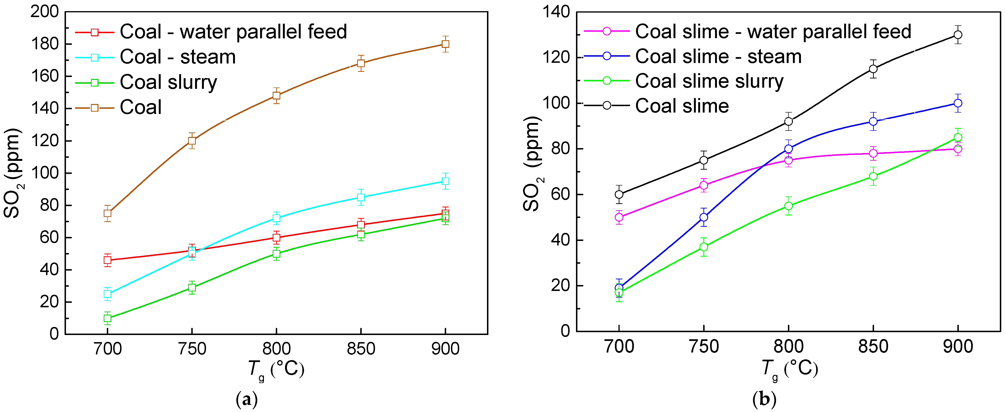
According to the data obtained (
Figure 12), the concentrations of sulfur oxides decreased by 30–75% when water was used in the combustion of dry coal fuels in the air. The minimum SO
2 emissions corresponded to the combustion of slurries within the whole temperature range. The difference in the concentrations between the slurries and dry coal components (coal/slime) burned in a steam-air environment varied in the range of 8–60%. This result is conditioned by the specific aspects of the gas-phase combustion of coal slime and coal. The creation of a steam-air environment contributed to the energy accumulation near the heated layer of coal particles, which activated the release of volatiles and led to the active oxidation of sulfur-containing components.
Figure 13 shows the trends (as illustrated by coal slime) constructed for the concentrations of sulfur oxides when varying the method of fuel combustion. At the stage of the release of volatile substances (gas-phase combustion, time interval 50–150 s), sulfur oxide concentrations were maximum and then they decreased. These amplitudes were minimum during the combustion of coal slime in the slurry composition. The presence of steam, on the contrary, intensified the formation of sulfur oxides at the stage of the release of volatile particles. The peak concentrations of SO
2 from the fuel combustion in a steam-air environment increased up to sevenfold relative to the slurry combustion. At the stage of heterogeneous combustion (time interval 200–700 s), the concentrations of sulfur oxides when steam was injected were higher than during the parallel introduction of the components, which increased the average concentrations (
Figure 10b). However, the duration of gas release when steam was injected decreased compared to the scheme in which water droplets were located near the coal sample on a substrate.
4.5. Relative Efficiency Indicators of Fuel Combustion
To determine the most efficient fuel, the relative efficiency indicators were calculated, controlling for the obtained energy and environmental characteristics. The weighted sum method (WSM) consisting of several stages was applied [
45]. The best value in each of the recorded parameters was chosen. Then the values were normalized relative to the best value. The best value for the gas-phase and heterogeneous ignition delay, ignition temperature and the concentration of anthropogenic emissions was the minimum one in a series. For the burnout coefficient and maximum combustion temperature, the maximum value in a series was chosen as optimal. At the final stage, relative efficiency indicators were given by:
where y
j is the weight for each criterion, and X
ij is the normalized value of a criterion.
All the weight coefficients totaled 1. In this research, all the weight coefficients were assumed equal. Using this approach, the best fuel is the one whose efficiency indicator (A
n) is maximum. The calculation results are presented in
Figure 14. It is shown how the complex efficiency indicator changes for the three considered methods for the combustion of coal components and water when varying the temperature in the combustion chamber. Within the whole range of temperatures in the furnace, the obtained coefficients for the slurry exceeded those for the fuels burned in the steam or air environment by 7–35% and 34–47%, respectively. This result shows great prospects of burning fuel slurries, especially those based on coal slime, because it is possible to significantly reduce the gas-phase and heterogeneous ignition delay times, minimum ignition temperature, concentrations of anthropogenic gases and losses due to incomplete burnout.
To illustrate the contribution of each component to the A
n coefficient, a vector diagram for the fuels based on coal slime is presented in
Figure 14, as the comparison of two coal components at 800 °C and 900 °C (
Figure 15) showed that slime-based slurries have the highest efficiency indicators. According to the data obtained (
Figure 15), six out of eight of the relative indicators under consideration for the slurry are maximum. The surface area for the slurry in the vector diagram is larger than for the two other examined methods for the combustion of slime and water. The biggest contribution to the above increase comes from the indicators of heterogeneous ignition, burnout and carbon dioxide emissions.
However, potentially negative aspects of slurry use are a decrease in available heat due to a lower calorific value. Therefore, it is advisable to carry out initial assessments of the boiler heat balance and changes in the efficiency coefficient when burning slurry or supplying steam. The parallel supply of water and the coal component is not considered in the calculation, since this method was characterized by lower values of the efficiency indicators (
Figure 14), in comparison with steam and slurry.
The heat balance of the boiler is determined by Equation (11):
where Q—the available heat of the fired coal; Q
1—heat usefully used in the boiler; Q
2—heat loss through stack gas; Q
3—heat loss by chemical unburned fuel; Q
4—heat loss owing to mechanical unburned fuel; Q
5—heat loss from external cooling; and Q
6—heat loss through the sensible heat of ash and slag.
To express the heat losses in percentages, we divide both sides by the Q:
The efficiency of the boiler can be assessed through the calculation of the efficiency coefficient. Boiler efficiency is defined by the ration of heat absorbed by the boiler and the heat provided by the fuel:
Available heat of the fired coal.
The total heat input to the fired coal is given by:
where, LHV—lower heating value; H
f—the sensible heat of the fuel; Q
wr—sensible heat carried by the air when heated by the external air heater; Q
wh—the heat of the fuel atomizing steam; and Q
cd—heat spent in the decomposition of carbonates.
The sensible heat of fuel (only for liquid and gaseous fuels) is given by:
where c
pf—specific heat of the fuel as received, and T
f—fuel temperature at the burner.
The heat carried by the air is determined only when it is preheated in a heater. In this calculation, we assume that Qwr = 0 MJ/kg.
The heat of the fuel-atomizing steam is given by
where G
s—specific steam consumption required for atomization of 1 kg of fuel; hs—enthalpy of steam for blowing (at an absolute pressure of saturated steam h
s = 2.79 MJ/kg); and h
fg—steam enthalpy contained in flue gases (conditionally taken equal to 2.5 MJ/kg).
The heat of the fuel atomizing steam during the dry coal combustion and slurry was assumed to be zero.
The heat spent in the decomposition of carbonates is taken into account only in cases of oil shale combustion. In this calculation, it is equal to zero.
Heat losses
The heat lost to flue gases is given by:
where h
fg—flue gas enthalpy; h
a0—theoretical cold air enthalpy entering the boiler; and α
ah—excess air coefficient of flue gases.
The flue gas enthalpy is determined from the reference data and depends on the flue gas temperature. Taking into account the fact that the normalized moisture content of dry coal and slime is Wn < 0.7%⋅kg/MJ, and that of slurry is 1 < Wn < 5%⋅kg/MJ, we accept the flue gas temperatures as 120 and 130 °C, respectively. Consequently, flue gas enthalpy for dry and wet fuels was 2.89 and 1.86 MJ/kg, respectively.
The heat loss owing to mechanical unburned fuel is determined according to reference data, taking into account the fuel type and combustion device. According to the data of [
46], during the combustion of coal waste with a normalized ash content A
n ≥ 1.4 kg/MJ, the value of q
4 is assumed to be 4%. During the combustion of coking coal, q
4 was taken to be equal to 8%. The losses with physical underburning during the combustion of slurry fuels decrease relative to coal and sludge, since CWS drops intensively fragment directly in the combustion chamber. For slurry, q
4 was taken to be equal to 2%.
The chemical incomplete combustion loss q3 is generally small. For example, for a pulverized coal furnace, q3 should be no more than 0.5%. During the combustion of CWS, the proportion of non-oxidized fuel is less. Water vapor formed during the injection of the fuel composition in the combustion chamber intensifies the oxidative processes. A similar process occurs with steam injection. Therefore, it was assumed that q3 for suspensions and steam injection was 0.2%.
Heat losses from external cooling q
5 are determined from empirical data depending on the boiler steam output [
46]. At the nominal steam capacity of the boiler D = 10 t/h, the heat loss from external cooling is 1.85%.
The heat loss through the sensible heat of ash and slag q
6 can be determined by the formula:
where α
ash—fly ash fraction; h
ash—ash enthalpy; and A
r—ash content of fuel per operating weight.
Based on the above methodology, the calculation of the heat balance of the boiler unit was carried out. Parameter values and calculation results are presented in
Table 3.
According to the
Table 3 estimates, it was found that the maximum boiler efficiency is achieved by slurry combustion. The value of η increased by 3.5–8% in comparison with the combustion of dry pulverized coal. Steam injection also led to an increase in efficiency, but the difference did not exceed 0.4%.
The experimental results contribute to the optimization of the fuel and steam-air medium supply modes (using separate nozzles or devices for the simultaneous supply of fuel and steam) to increase the efficiency of fuel combustion and minimize emissions. The results obtained can be used in technologies for preparing fuel for combustion by its fine and uniform atomization, as well as mixing with an oxidizing agent. This direction is applicable in the design of nozzles and burner devices. In practice, the use of water in the composition of fuel slurries or the creation of a vapor-air medium in the combustion chamber will solve several significant problems such as reducing heat loads, preventing detonations in combustion chambers, and intensifying the micro-explosive dispersion of slurry. The creation of a finely dispersed gas-droplet flow, which ensures the efficient mixing of combustible components and oxidizers, in turn, prevents the clogging and coking of nozzles and burners.


