Article

Unsteady Study on the Influence of the Angle of Attack of the Blade on the Stall of the Impeller of the Double-Suction Centrifugal Pump

1
School of Energy and Power Engineering, Lanzhou University of Technology, Lanzhou 730050, China
2
Innovation Research Center for Advanced Equipment of Nuclear Class Pumps, Lanzhou University of Technology, Lanzhou 730050, China
*
Author to whom correspondence should be addressed.
Energies 2022, 15(24), 9528; https://doi.org/10.3390/en15249528
Submission received: 15 November 2022 / Revised: 30 November 2022 / Accepted: 13 December 2022 / Published: 15 December 2022
(This article belongs to the Special Issue Complex Flow in Fluid Machinery)

Abstract

:
In order to clearly show the influence on the rotating stall of the impeller of a double-suction centrifugal pump, this paper, using the numerical simulation method of Shear Stress Transform (SST), analyzes the effects of different inlet angles of the blade on hydraulic performance, internal flow field and pressure pulsation in the impeller. The results show that the small angle of attack of the blade inlet scheme can effectively suppress the impeller rotation stall and that the design point head and efficiency are increased by 6.4% and 5.7% respectively. This paper, using turbulence intensity to determine the generation of rotating stall, proposed that the average of turbulence intensity exceeding 2% is a necessary condition for the generation of rotating stall and discovered that the standard deviation of the big angle of attack of the scheme is always greater than that of the small angle being analyzed by the impeller pressure pulsation. The basic critical frequencies of blade inlet pressure pulsation with components of a low frequency is dominated by the impeller rotating frequency F0 and its harmonic frequencies 2F0, and 3F0, but the basic critical frequencies of blade outlet pressure pulsation is governed by Blade Passing Frequency (BPF). The research results can provide some theoretical support for stall research and hydraulic performance optimization of a double-suction pump.

1. Introduction

At present, centrifugal pumps are widely used in the field of machinery and equipment, while many problems can also be found in the operation like stall, cavitation, noise, vibration and other serious hazards [1,2,3,4]. Therefore, there is huge potential and challenge in how to avoid these problems during all the working conditions in terms of sustainable energy-efficient operation.
The main problem that often occurs within centrifugal pumps for low-flow conditions is the rotating stall of the impeller. Unless the rotating stall mechanism is studied in depth, the rotating stall of the impeller will consistently influence the stable operation of the centrifugal pumps under low-flow conditions, thus resulting in a sharp decline of performance and seriously affecting industrial production [5,6,7,8,9]. The concept of stall is first derived from aerodynamics for the study of airfoil [10,11] and is the lift force suddenly being reduced when the angle of attack of the airfoil increases to a critical value. Zhou et al. used the turbulence model of Large Eddy Simulation (LES) to calculate a centrifugal pump and found that the volute–impeller interaction plays a dominant role in the impeller stall flow channel [12]. Huang et al. adopted a third-order nonlinear SGS model to study a centrifugal pump rotating stall at 0.25Q operating conditions, source and rotating terms and found that the combined effect of the source and rotating terms led to a non-uniform distribution of Reynolds stress [13].
Based on the turbulence model of Shear Stress Transfer (SST), Li et al. proposed that the trajectory of the wheel edge leakage flow pattern could be used as a criterion for the occurrence of rotating stall [14]. Zhang et al. used the SST-SAS turbulence model to simulate the pump conditions and discovered the mechanism of the circumferential rotation of the stall vortex [15]. Sano et al. investigated the rotating stall of the impeller and guide vane runners using a combination of experiments and computing fluid dynamics (CFD) and found that a “hump” exists in the external characteristic head curve of the pump occurring at low-flow conditions [16,17,18,19,20]. As far as the current research is concerned, most of the research results still focus on the propagation and transportation of stall masses, but there is still little relevant literature to study the pressure pulsation of the double-suction centrifugal pump under low-flow conditions.
The paper designed two schemes of blade inlet angles to alter the angle of attack using the velocity triangle method, obtained the pressure pulsation of the internal flow field of the double-suction centrifugal pump through streamline; relative velocity vector, turbulence vortex frequency and turbulence kinetic energy; and analyzed the turbulence intensity, pressure standard deviation and time–frequency characteristics of pressure pulsation based on the fast Fourier transform. The results can provide a theoretical basis for the safe and stable operation of a centrifugal pump in the trend of sustainable development.

2. The Design Process

2.1. The Parameters of Design

A horizontal mid-opening double-suction centrifugal pump is studied in this paper. The main parameters are shown in Table 1.

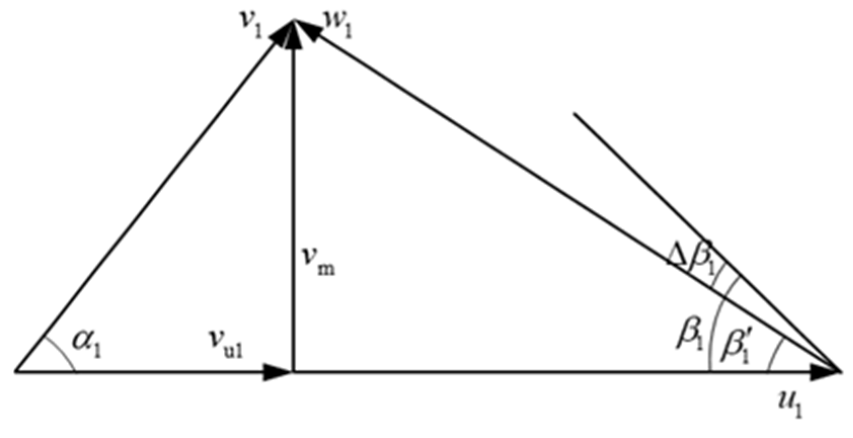
2.2. The Design of Blade Inlet Angle

According to the definition of rotating stall, the rotating stall phenomenon is caused by an excessive angle of attack. The blade inlet angle is superimposed by the blade inlet relative liquid flow angle and the blade inlet angle of attack [21,22,23,24,25]. Therefore, the calculation of the blade inlet angle is a prerequisite for the study of the rotating stall characteristics of double-suction pumps under low-flow conditions.
The paper adopts the velocity triangle method to calculate the blade inlet angle [1]. The velocity triangle at the blade inlet of the impeller of a double-suction pump is shown in Figure 1. β 1 is the blade inlet angle. β 1 is the relative liquid flow angle at the blade inlet. Because of β 1 < β 1 , Δ β 1 = β 1 β 1 , Δ β 1 is defined as the angle of attack at the blade inlet. Meanwhile, v 1 is the blade inlet absolute velocity, u 1 is the circumferential velocity at the blade inlet, and w 1 is the velocity of involvement at the blade inlet. When liquid is flowing, the velocity in the circumferential direction v u 1 of v 1 is zero for suction chamber with the design of straight taper and it means that v u 1 is equivalent to shaft surface velocity v m at the blade inlet. But v u 1 of v 1 is not zero because of semi-spiral suction chamber. Therefore, the velocity in the circumferential direction v u 1 is not ignored in the design of the impeller of a double-suction pump.
v m 1 = Q η v 2 π R c 1 b 1 ψ 1
η v = 1 0.028 ( n s 100 ) 0.6
n s = 3.65 n Q 0.5 H 0.75
where Q is nominal flow rate, η v is volumetric efficiency, n s is specific speed, n is rotational speed, H is nominal head, R c 1 is center of gravity radius at the blade inlet, b 1 is width at the blade inlet and ψ 1 is displacement factor at the blade inlet.
ψ 1 = 1 z s u 1 D 1 π = 1 z s 1 D 1 π sin β 1 = 1 δ 1 z D 1 π 1 + ( cot β 1 sin λ 1 ) 2
where z is impeller blade number, D 1 is diameter at the blade inlet, s u 1 is circumferential thickness at the blade inlet, s 1 is thickness in the direction of flow at the blade inlet, δ 1 is real thickness of blade and λ 1 ( λ 1 = 60 90 ) is clamping angle of flow direction and axial direction.
u 1 = D 1 π n 60
tan β 1 = v m 1 u 1 v u 1
v u 1 = m Q 2 n 3 R 1
where R 1 is the inlet radius of streamline, m ( m = 0.055 0.08 ) is a coefficient and the value is determined on the specific speed n s . The larger the specific speed is, the larger m will be. In this paper, m = 0.07.
After calculation, the final result is β 1 a = 10.9 , β 1 b = 14.7 and β 1 c = 19.2 . The details of schemes A and B that adopted different angles of attack are shown in Table 2.

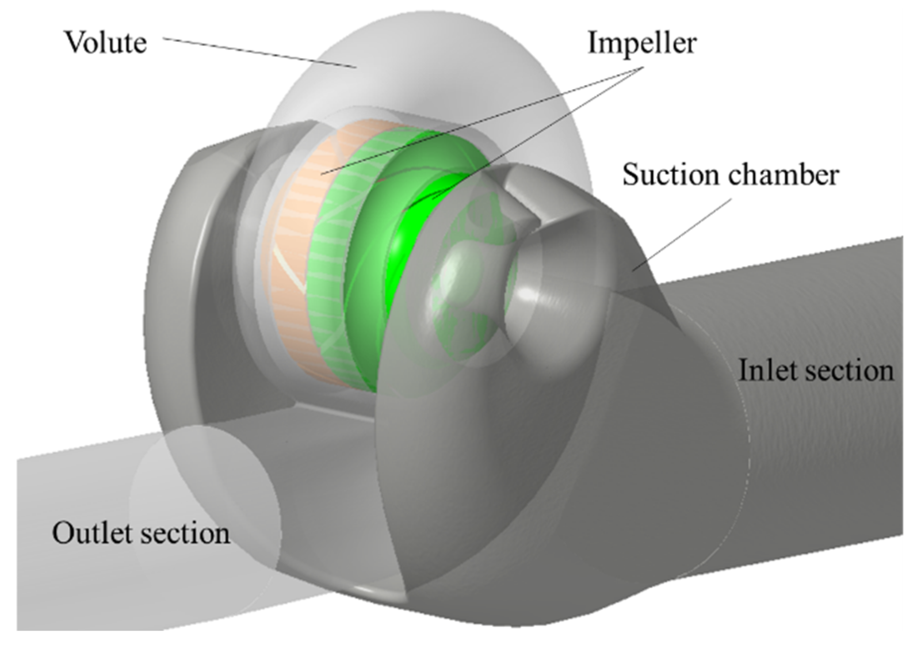
3. Computational Model

3.1. Numerical Grid and Computational Details

The main water-body parts, such as the suction-chamber, impeller and volute, were established by the software Pro/E 5.0(The company of Parametric Technology Corporation(PTC), Massachusetts, USA). With the geometric structure parameters of the pump being constants, the inlet and outlet parts were properly extended to improve the accuracy of the calculation. The calculation domain model is shown in Figure 2.
Icem CFD software (The company of Analysis of Systems(ANSYS), Pennsylvania, USA.) was used to discretize the double-suction centrifugal pump model, and a well-adapted unstructured mesh was used because of the complex structure of the model. More importantly, in order to improve the simulation accuracy, the parts with large and precise distortion, such as the impeller, suction chamber and volute, adopted the partial improvement of grid density and the boundary layer grid, as shown in Figure 3.
The Shear Stress Transfer (SST) turbulence model, combining the advantages of the standard k ε model and the Wilcox k ω model, was chosen to improve the computational efficiency because it can call the Wilcox k ω model at the near-wall surface to capture the fluid flow in the viscous sublayer and call the standard k ε model at the mainstream to calculate with better robustness. In the CFX 15.0 settings, the dynamic–static interface was set to the frozen rotor for steady formulation and the transient stator for unsteady formulation. The inlet boundary condition is the mass flow rate, and the outlet boundary is outflow. The automatic wall function was used, and the solid wall surface was set as a no-slip wall. The numerical calculation precision was 1 × 10 5 . The unsteady numerical calculation took the converged steady numerical calculation result as the initial condition and set the time step as 3.367 × 10 4 seconds, which is the time required for the impeller to rotate by 2 degree. Ultimately, monitoring points were set in the middle of the impeller flow channel inlet and outlet as shown in Figure 4.

3.2. Grid Validation and Y Plus

Grid independence verification is a critical state that reflects the influence of the number of grids on the calculation results. In order to make reasonable computational resources and save computational time, grid independence verification is necessary to ensure the accuracy and economy of the numerical simulation at the same time. Five sets of grids are used to verify the independence, and the results are shown in Figure 5. As the number of grids increases, the head increases and the efficiency first increases and then decreases. When the number of grids reaches 1.22 × 10 7 , the head basically remains the same and the efficiency reaches the maximum. Considering the efficiency and accuracy of the calculation, the number of numerical grids is 1.22 × 10 7 .
In this paper, the SST k ω turbulence model is mainly used to capture the rotating stall vortex structure near the inlet side of the impeller blade. However, this turbulence model has the highest mesh requirement in the fluid mechanical calculation, which means that Y plus the value of the wall surface is less than five. Figure 6 shows the Yplus, distribution cloud of the double-suction pump impeller blade. The average Yplus value is 4.1, which meets SST k ω turbulence model requirements.

3.3. FFT Theory

3.3.1. Background

Fast Fourier Transform (FFT) analysis was performed to find the amplitude of static pressure fluctuations for various conditions from the numerical data. Turbulent pulsation without consideration of fluid compressibility and pulsating source pulsation without consideration of viscosity are two different properties of fluid pressure pulsation. When the pump is operating in the design condition as well as the other conditions, there are usually two kinds of pressure pulsation, one is a stable periodic signal, and the other is a random signal containing the periodic signal. However, according to the pressure pulsation components in the pump, the pressure pulsation can be divided into three categories [26,27,28,29,30,31]: the first category is the regular periodic variation of the impeller rotating frequency octave pulsation; the second category is the regular variation of the lobe frequency octave pulsation; the third category is the random pulsation generated by random disturbance factors close to the white noise frequency. It is worth noting that a high-amplitude pulsation phenomenon will have an abnormal impact on the operation of the pump, resulting in vibration, noise, structural damage or even the failure of the pump. In this paper, the pressure pulsation is analyzed by the fast Fourier transform (FFT) of the rotating stall in the numerical simulation by the real-time monitoring of the static pressure at the monitoring points in Figure 3.

3.3.2. Theory

The fast Fourier transform (FFT) theory can change the time-domain relationship of the static pressure directly into the frequency-domain relationship. For the time-domain relationship, time is used as the horizontal axis and the physical parameters to be analyzed as the vertical axis. For the frequency-domain relationship, it filters all the complex components of the pressure pulsation signal and then plot the frequency-domain curve according to frequency, with the frequency as the horizontal axis.
(1)
Time-domain relationships theory
a. Standard deviation theory
The standard deviation can directly indicate the size of the fluctuation deviation of the overall data for the physical parameters to be analyzed from its mean and the dispersion degree of the overall data distribution [32]. The smaller the standard deviation, the closer the individual data are to the overall mean, and vice versa. Defining pressure standard deviation P s as
P s = i n ( P i P ¯ ) 2 n 1
where P ¯ is the average static pressure, P i is the transient static pressure, and n is the number of pressure data.
b. Time-domain curve
Due to the viscous effect of the fluid and the static and dynamic interference between the rotating parts and stationary parts, the flow field in the centrifugal pump shows unsteady flow characteristics [33,34,35]. Defining the dimensionless pressure coefficient as
C p = P i P ¯ 0.5 ρ U 2
where ρ is the density of water under 25 °C (kg−1·m3) and U is the circumferential velocity of impeller outlet, it is calculated that U is 27.9774 m−1·s.
(2)
Frequency-domain relationships theory
Assuming X ( n Δ t ) is a finite sequence of length M , the expression for the discrete value X ( m ) (m = 0, 1, 2, …,) of the spectrum X ( f ) is
X m = X ( m Δ f ) = n = 0 M x ( n Δ t ) exp ( j 2 π n m M ) M
where Δ f is frequency resolution, M is the number of sampled data points and Δ t is the time interval of data sampling.

4. Results and Analysis

4.1. Validation of the Numerical Model

The schematic diagram of the experimental system is shown in Figure 7. The experimental system is mainly composed of the control system, model pump, torque sensor, electromagnetic flow-meter and multi-channel acquisition instrument. Data measurement is started after the experimental pump runs smoothly for a period of time, in which the inlet and outlet pressure is measured by the pressure sensor and the flow rate is measured by the flow meter. Notably, the motor input power is calculated by measuring the torque and rotating speed, in which the flow rate, the torque and rotating speed are read on the torque speed sensor. The CFD numerical simulation is used to calculate the head and efficiency of the double-suction centrifugal pump at different flow operating points. The results are compared with the test results to verify the reliability of the numerical simulation.
The pressure values of the inlet and outlet pressure gauge of pump, head and efficiency are obtained by the Equations (11) and (12). Additionally, the overflow flow is measured by the ultrasonic flow meter without disturbing the fluid flow state.
H = P out P in ρ g + v out v in 2 g + Δ Z
η = ρ g Q H P
where P in and P out are the inlet and outlet pressure of the pump, respectively; v in and v out are the inlet and outlet velocity of the pump, respectively; Δ Z is the horizontal height difference.
For scheme A, the external characteristics tests were conducted at operating conditions of 1.0Q, 0.8Q, 0.5Q and 0.35Q, and the comparison results between the obtained experiments and numerical simulations are shown in Figure 8. By monitoring the head of the double-suction centrifugal pump at the four working conditions, the results show that the calculating deviations of scheme A are 0.16%, 0.28%, 0.13% and 0.23%, respectively, and that the calculating deviations of scheme B are 0.64%, 0.22%, 0.52% and 0.31%, respectively, which are within the calculated requirements. Under the designed condition of 1.0Q, the head of the double-suction centrifugal pump of schemes A and B is 36.78 and 38.39 m, the errors of which are 2.3% and 6.4%, respectively, compared with the experiment head of 35.95 m. Furthermore, the efficiency of the double-suction centrifugal pump of schemes A and B is 0.9195 and 0.9239, the errors of which are 5.3% and 5.7%, respectively, compared with the experiment efficiency of 0.8713. The experiments results show that the numerical method adopted in this paper can reflect the external characteristics of the double-suction centrifugal pump more accurately.

4.2. Internal Characteristic Analysis

4.2.1. Internal Flow Analysis

Figure 9 shows the relative velocity streamline of the middle section of the impeller of schemes A and B under conditions of 0.35Q, 0.50Q and 0.80Q. It can obviously be seen that the phenomenon of flow separation (as shown in the red circles) and a rotating vortex is generated at the blade suction surface of schemes A and B under conditions of 0.35Q and 0.50Q. However, although there is a weak flow separation phenomenon under the condition of 0.8Q, the rotating stall vortex is not formed. Based on the discussion above, it can be judged that a rotating stall appeared in the impeller channels of schemes A and B under conditions of 0.35Q and 0.50Q. Moreover, under the same stall condition, the larger the inlet stroke angle is, the larger the stall vortex distribution range will be, and thus the intensity between the stall vortex and the impeller blade is stronger.
The view of internal flow for schemes A and B are described respectively in Figure 10 and Figure 11, including the relative velocity streamlines, relative velocity vector, turbulent vortex frequency and turbulent kinetic energy located at the impeller stall vortex. The vortex was generated under conditions of 0.35Q and 0.50Q from the relative velocity streamline and relative velocity vector, which was again verified by the rotational stall phenomenon at the blade suction surface of the impeller channel of the double-suction centrifugal pump. The flow separation phenomenon generated in the impeller channel will result in higher turbulence frequency and turbulent kinetic energy at the separation position. Figure 10 and Figure 11 show that the distribution range of a stall vortex in the impeller channel of scheme A is larger than that of scheme B, which causes the turbulence eddy frequency distribution range of the impeller channel of the scheme A to be larger than that of scheme B.
The turbulence kinetic energy distribution shows that the turbulence kinetic energy in the impeller channel of scheme A is about twice that of scheme B and that the turbulence kinetic energy of the rotating stall vortex increases with the flow rate increasing.

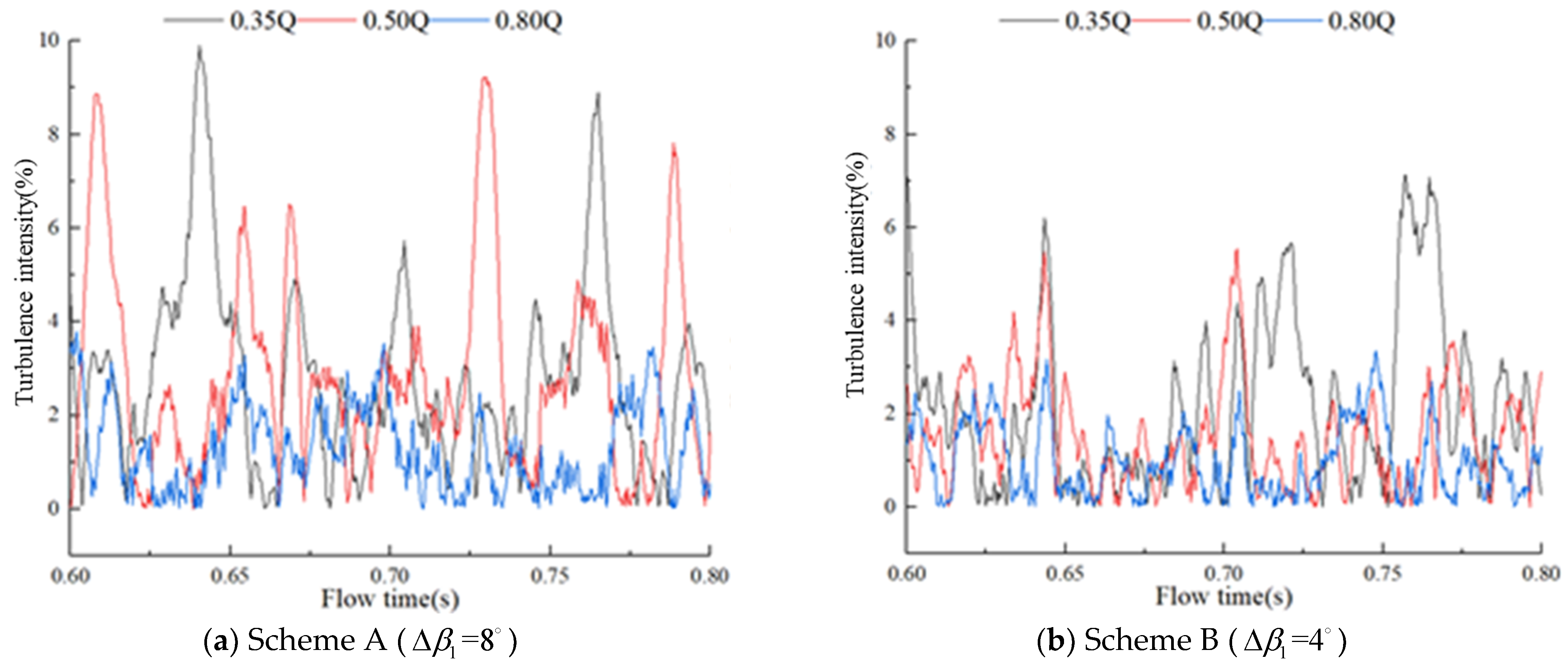
4.2.2. Turbulence Intensity Analysis

The generation of rotating stall can greatly affect the flow structure in the impeller under low-flow conditions, which enhances the degree of turbulence because of a rotating stall vortex. The paper adopted the turbulence intensity applied in aircraft engines to analyze quantitatively the mechanism of rotating stall generation in a double-suction centrifugal pump [36]. Since the fluid in the aircraft engine is connected to the open atmosphere, the atmospheric pressure needs to be considered, while the fluid in the pump is in a closed environment, so the reference pressure value is zero.
Define the turbulence intensity ε of centrifugal pump as
ε = | 1 T 0 T ( P ( t ) P ¯ ) 2 d t P ¯ + P 0 |
where P ¯ is the average static pressure during the time of T , P ( t ) is the transient static pressure, T is the integral time, and P 0 is the ambient reference pressure.
The transient static pressure data obtained from monitoring point I1 at the impeller inlet of schemes A and B in the time period of 0.60–0.80 s were taken, which was processed into the curve of turbulence intensity as shown in Figure 12. From the two figures, it can be seen that the change in the turbulence intensity of 0.80Q is significantly smaller than that of 0.35Q and 0.50Q and that the change in the turbulence intensity fluctuation of 0.80Q is smoother than that of 0.35Q and 0.50Q. Combined with Figure 8, rotating stall was not generated in the flow channel of the impeller at 0.80Q, while a low-pressure rotating stall vortex was generated in the flow channel of the impeller at 0.50Q and 0.35Q. The mean values of turbulence intensity of scheme A at 0.35Q, 0.50Q and 0.80Q were 2.72%, 2.75% and 1.26%, respectively, and the mean values of turbulence intensity of scheme B at 0.35Q, 0.50Q and 0.80Q were 2.36%, 2.09% and 0.95%, respectively, from which it can be clearly seen that the turbulence intensity of scheme A was higher than that of scheme B. Therefore, the mean values of turbulence intensity near the blade inlet of the impeller is not less than 2% under 0.35Q and 0.50Q stall conditions for both schemes A and B.

4.3. Pressure Pulsation Analysis Based on FFT

4.3.1. Comprehensive Analysis of Pressure Fluctuation

The standard deviation can reflect the dispersion degree of a set of data. This paper uses the standard deviation to characterize the deviation of the transient static pressure of monitoring points from the mean static pressure, which reveals the pressure pulsation characteristics of the internal flow field influenced by the size of the blade inlet angle of attack of the double-suction centrifugal pump.
Figure 13 shows the results of the standard deviation values of the static pressure at inlet monitoring points I1 and I2, as well as the outlet monitoring points O1 and O2 of the impeller channel under different flow rates. It can be seen that the pressure pulsation amplitude at the monitoring points at the inlet of the impeller channel is always lower than that at the monitoring point at the outlet under the conditions of 0.35Q, 0.5Q and 0.8Q, which is mainly caused by the dynamic–static interference effects between the impeller and the spacer of the volute. There are two main reasons for the pressure pulsation amplitude at the monitoring points of scheme B always being lower than that at the monitoring point of scheme A. One is the vortex effect generated when the upstream fluid flows through the semi-spiral suction chamber, and the other is the mismatch between the inflow angle in the flow channel and the blade inlet angle leading to flow separation in the low-pressure area at the inlet. The instability of the internal flow field caused by the synergistic effect of the two reasons above, which is because the vortexes generated from upstream and transported to the downstream will collide and collapse. However, the main reason is that rotating stall vortex is constantly acting on the flow channel of the impeller. As the flow rate increases, the standard deviation amplitude of pressure pulsation at each monitoring point shows a decreasing trend. On the one hand, due to the flow field in the upstream suction chamber becoming uniform, the vortex effect is weakened or even disappears, thus reducing the effect on the downstream flow field; on the other hand, the number of rotating stall vortexes generated by the flow separation in the impeller flow channel is decreased. Moreover, the effect of the rotating stall vortex on the structure of the internal flow field is weakened.

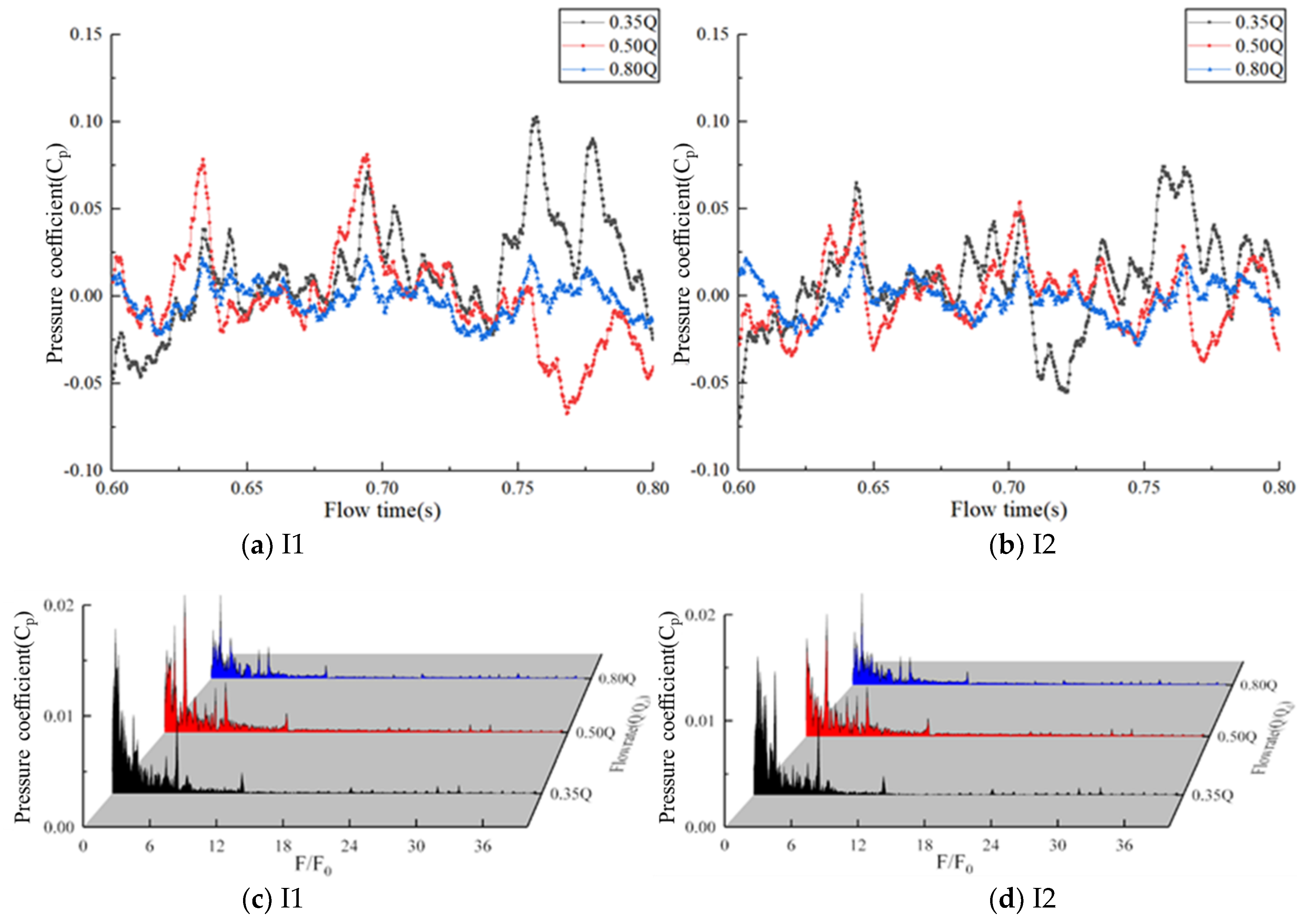
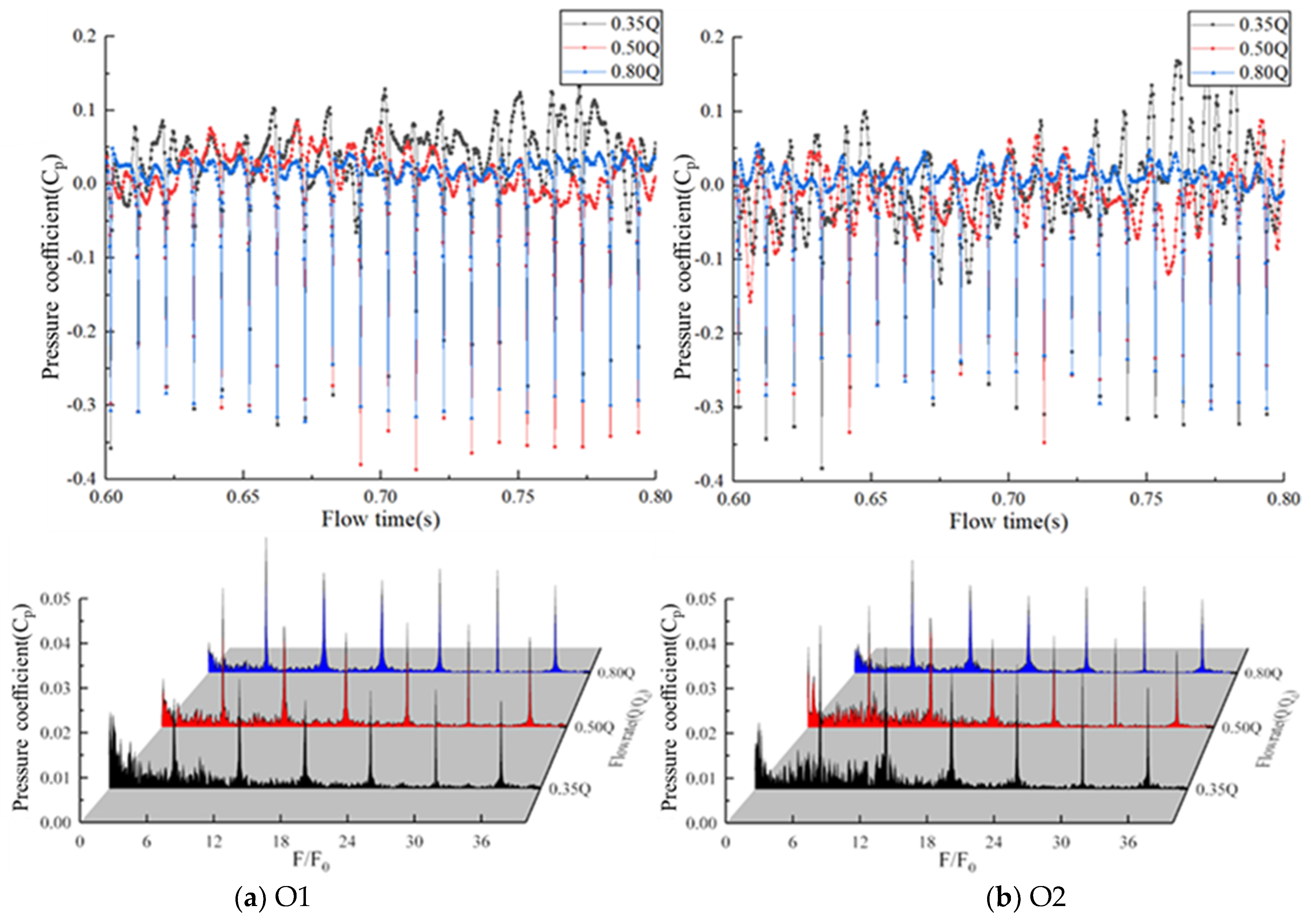
4.3.2. Analysis of Pressure Pulsation at Different Positions under Different Conditions

This paper selected the data, that is static pressure in three cycles after the 0.6 s (ten cycles) of pump operating, to analyze. Figure 14 and Figure 15 respectively show the time-domain and frequency-domain curves of monitoring points I1 and I2 at the inlet of impeller channel for schemes A and B. F is the pulsation frequency of the static pressure coefficient at the monitoring point, and F0 is the impeller rotating frequency of the impeller.
As can be seen from the frequency-domain curve in Figure 14, the main frequency of the static pressure coefficient pulsation is double the impeller rotating frequency, and with the decrease of the flow rate, the main frequency pulsation amplitude shows the law of increasing and then decreasing, and the main frequency amplitude at 0.80Q, 0.50Q and 0.35Q are 0.017, 0.024 and 0.021, respectively. As can be seen from the frequency-domain curve in Figure 15, the main frequency of the static pressure coefficient pulsation is also double the impeller rotating frequency, and as the flow rate decreases, the main frequency pulsation amplitude shows the law of increasing and the main frequency amplitude at 0.80Q, 0.50Q and 0.35Q are 0.009, 0.016 and 0.018, respectively. The law of the frequency-domain curve is consistent with that of the time-domain curve, and the pulsation amplitude of scheme A is always larger than that of scheme B. Meanwhile, there is a low-frequency pulsation component in the frequency-domain curve, showing the characteristics of a low-frequency line spectrum. Meanwhile, this is mainly due to the flow separation of the low-pressure area at the suction surface of the impeller blade, and the phenomenon of rotating stall is generated, which verifies the analysis results of the time-domain curve again.
Figure 16 and Figure 17 respectively show the time-domain and frequency-domain curves of monitoring points O1 and O2 at the outlet of impeller channel for schemes A and B. F is the pulsation frequency of the static pressure coefficient at the monitoring point, and F0 is the impeller rotating frequency of the impeller.
From the time-domain curve in Figure 16, it can be seen that the transient static pressure pulsation amplitude of 0.8Q is lower than that of 0.5Q and 0.35Q. There is no certain regularity in each cycle but a certain regularity among cycles. There is a very low trough in each cycle under 0.35Q, 0.50Q and 0.80Q conditions as well as the trough of 0.50Q being slightly lower than that of 0.35Q. From the time-domain curve in Figure 17, it can be seen that the transient static pressure pulsation amplitude of 0.8Q is also lower than that of 0.50Q and 0.35Q, while the pulsation of transient static pressure coefficient of monitoring points at the outlet of the impeller channel of scheme B is overall larger than that of scheme A. There is strong periodicity and six troughs, which is consistent with the number of impeller blades, in each cycle, so the impeller outlet of scheme B is strong. However, it cannot be attributed to the impeller outlet of scheme A not being subject to the role of static–dynamic interference, and the role of impeller of scheme B is not more obvious, which may be due to the flow structure of impeller flow channel of scheme A being not inferior to that of scheme B. Moreover, the dynamic–static interference between impeller and volute has most important impact on this phenomenon.
From frequency-domain curve in Figure 16, it can be seen that the main frequency of the transient static pressure coefficient pulsation is one times the impeller rotating frequency. With the flow rate decreasing, the main frequency amplitude of the transient static pressure coefficient pulsation is showing an increasing law, and the main frequency amplitude of 0.80Q, 0.50Q and 0.35Q are 0.032, 0.133 and 0.146, respectively. The frequency of the transient static pressure coefficient pulsation is dominated by the regular impeller rotating frequency octave and mixed with random low-frequency pulsation. From the frequency-domain curve in Figure 17, it can be seen that the main frequency of the transient static pressure coefficient pulsation is six times the rotational frequency, called the blade passing frequency (BPF), and the frequency of the transient static pressure coefficient pulsation is dominated by the regular BPF and mixed with random low-frequency pulsation. The amplitude of the main frequency pulsation of the transient static pressure coefficient of monitoring points at the impeller outlet of scheme A is always larger than that of scheme B, and the difference between the two amplitudes is around 0.1. Hence, it can be indicated that the internal flow field in the impeller of scheme B is mainly influenced by rotating the impeller, and the internal flow field in the impeller of scheme A is mainly influenced by the dynamic–static interference between the impeller and the suction chamber. Meanwhile, the internal flow field structure in the impeller of the scheme B is inferior to that of scheme A under low-flow conditions, and the flow separation phenomenon in the flow channel in the impeller for scheme A is serious, which generated a rotating stall vortex to transport to the surface of the structure, which can produce huge pressure to influence the impeller structure and even generate vibration and noise problems.
For the analysis of pressure pulsation at the pressure and the suction surface of the blade, combined with the previous discussion, this paper selects the transient static pressure data to analyze when 0.5Q. On the one hand, there is obviously unsteady flow phenomena, such as a rotating stall vortex in the internal flow channel of schemes A and B when 0.5Q. On the other hand, the transient static pressure coefficient pulsation phenomenon, especially low-frequency pressure pulsation, is pretty significant.
Figure 18 and Figure 19 show the frequency-domain curves of monitoring points at the blade pressure and suction surface of schemes A and B, respectively. From Figure 18, it can be seen that the main frequency of the transient static pressure coefficient pulsation of monitoring points at the blade suction surface is the impeller rotating frequency. The main frequency pulsation amplitude is an increasing trend from monitoring point S1-1 of the blade inlet to monitoring point S1-3 of the blade outlet, and the main frequency pulsation amplitude of scheme A is always larger than that of scheme B. From Figure 19, it can be seen that the main frequency of the transient static pressure coefficient pulsation of monitoring points at the blade pressure surface is dominated by impeller rotating frequency. Furthermore, the main frequency pulsation amplitude is an increasing trend from monitoring point P1-1 of the blade inlet to monitoring point P1-3 of the blade outlet, and the main frequency pulsation amplitude of scheme A is always larger than that of scheme B, which is consistent with the law of the suction surface of the blade. Moreover, the transient pressure coefficient pulsation of schemes A and B has a period of low-frequency pulsation, and the low-frequency pulsation harmonic amplitude of scheme A is larger than that of scheme B, which is caused by unstable flow, especially the rotating stall vortex in the impeller flow channel, combined with the discussion of the pulsation amplitude of the monitoring points of the impeller flow channel. The larger the pressure pulsation amplitude is, the easier it will be to generate the problems of impeller structure surface, which will lead the blade load to be unstable. Unless the blade load will not be larger, the rotor will conduct displacement to produce vibration, noise and other problems.

5. Conclusions

The paper analyzes the mechanism of rotational stall in the impeller of a double-suction centrifugal pump by adding different angles of attack to the blade inlet angle, conducts discussions of the internal flow and pressure pulsation and reveals the stall mechanism and the law of pressure pulsation.
(1)
The internal flow field of the impeller was analyzed by means of streamlines, and the location of the rotating stall vortex generation was found to be located near the suction surface of the blade, which was verified again by the relative velocity vector contour. Based on the turbulence frequency contour, it was found that the rotational frequency of rotating stall vortex in this double-suction pump is about 2000 Hz, and its turbulent energy is also higher.
(2)
Based on turbulence intensity to analyze quantitatively the internal flow of the impeller, it is concluded that the volatility of the turbulence intensity fluctuation in the impeller is enhanced, with the blade inlet angle increasing. Moreover, when the mean value of turbulence intensity is more than 2%, the rotational stall occurs near the impeller blade inlet, so the turbulence intensity can be used to judge whether the rotational stall phenomenon occurs.
(3)
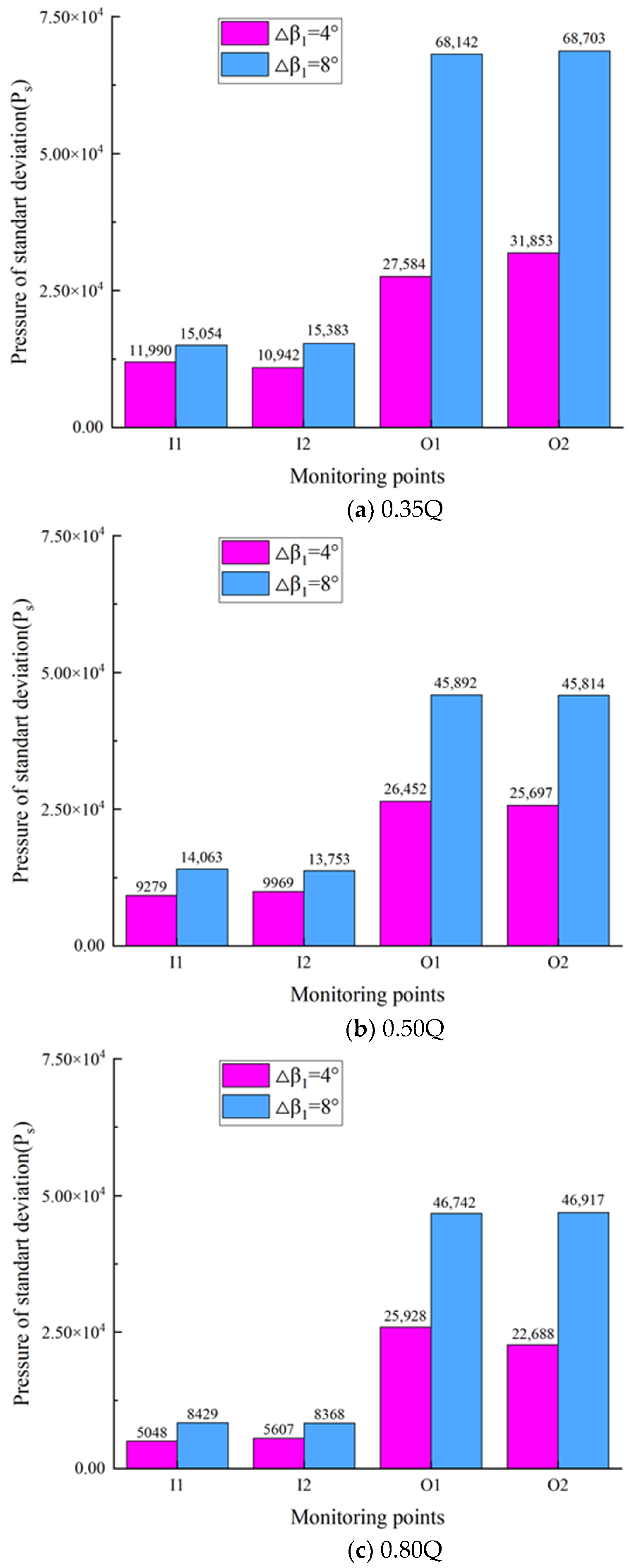
The pressure pulsation was investigated using standard deviation, showing that the blade inlet angle of attack has a significant effect on the impeller rotating stall. The rotating stall vortex increases the amplitude of pressure pulsation at the blade inlet of the impeller. Therefore, the standard deviation of pressure coefficient can be used as a standard to measure the rotating stall of centrifugal pumps, which can provide a reference for the optimization of the design of the impeller blade to improve the performance of centrifugal pumps.
(4)
FFT was used to analyze the pressure pulsation of monitoring points in the impeller, and it was found that the rotating stall would lead to the existence of a low-frequency pulsation component of the pressure pulsation at the blade inlet. Under the rotating stall condition, the larger the angle of attack of the impeller blade is, the higher the amplitude of low-frequency pulsation will be. Impeller rotating frequency is the main frequency of pressure pulsation in the impeller of a double-suction centrifugal pump, and the stall vortex has a great influence on the pressure pulsation in the impeller.

Author Contributions

Conceptualization, H.W. and S.Z.; methodology, Y.L.; software, T.N.; validation, H.W., Y.L. and Y.K.; formal analysis, H.W.; investigation, H.W.; resources, Y.L.; data curation, H.W.; writing—original draft preparation, H.W.; writing—review and editing, H.W.; visualization, S.Z.; supervision, Y.L.; project administration, Y.L.; funding acquisition, Y.L. All authors have read and agreed to the published version of the manuscript.

Funding

The National Natural Science Foundation of China (51866009); Gansu Provincial Educational Department of China: Excellent Graduate Student “Innovation Star” Project (2022CXZX-440).

Data Availability Statement

Not applicable.

Conflicts of Interest

The authors declare no conflict of interest.

Nomenclature

Nominal flow rate, kg/m3Q
Nominal head, mH
Nominal rotation speed, rpmn
Nominal efficient, % η
Nominal shaft power, kWP
Impeller blade numberZ
Blade inlet angle, degree β 1
The relative liquid flow angle at the blade inlet, degree β 1
Angle of attack at the blade inlet, degree Δ β 1
Specific speed n s
Blade inlet absolute velocity, m/s v 1
Circumferential velocity at the blade inlet, m/s u 1
The velocity of involvement at the blade inlet, m/s w 1
Shaft surface velocity, m/s u m
The circumferential components of absolute velocity, m/s v u 1
Inlet pressure of pump, Pa P in
Outlet pressure of pump, Pa P out
Inlet velocity of pump, m/s v in
Outlet velocity of pump, m/s v out
Height difference horizontally, m Δ Z
Turbulence intensity ε
Pressure standard deviation P s
Pressure coefficient C p

References

  1. Guan, X. Modern Pump Theory and Design, 2nd ed.; China Aerospace Publishing House: Beijing, China, 2011; pp. 284–296. [Google Scholar]
  2. Johann, F.G. Centrifugal Pumps, 2nd ed.; Springer: Berlin/Heidelberg, Germany; New York, NY, USA, 2008; pp. 574–591. [Google Scholar]
  3. Lang, T.; Liu, Y.; Chen, K.; Xu, E.; Jin, L.; Jiang, X. Review of research on hydrodynamic noise of centrifugal pump. J. Drain. Irrig. Mach. Eng. 2011, 39, 8–15+22. [Google Scholar]
  4. Tong, Z.; Xin, J.; Tong, S.; Yang, Z.; Zhao, J.; Mao, J. Study on flow structure, performance optimization and fault detection in centrifugal pump: A review. J. Zhejiang Univ. -Sci. A 2020, 21, 85–117. [Google Scholar] [CrossRef]
  5. Yang, H.; Zhao, G.; Liang, H. Research progress on influence factors of airfoil dynamic stall and flow control. Chin. J. Aeronaut. 2020, 41, 125–150. [Google Scholar]
  6. Wu, L.; Jiang, Y.; Liu, X. Numerical analysis of dynamic stall characteristics of several bionic airfoils. J. Xi’an Jiao Tong Univ. 2022, 9, 1–9. [Google Scholar]
  7. Yang, J.; Yuan, S.; Pei, J. Overview of rotating stall in centrifugal pumps with vaned diffuser. J. Drain. Irrig. Mach. Eng. 2015, 33, 369–373. [Google Scholar]
  8. Zhang, L.; Wang, S.; Hu, C. Research progress of rotating stall in turbo machinery. Therm. Power Gener. 2014, 43, 1–5+25. [Google Scholar]
  9. Pan, Z.; Li, J.; Li, H. Overview for Research on Rotating Stall of Pump. Fluid Mach. 2011, 39, 35–39. [Google Scholar]
  10. Wang, F. Methods for Flow Analysis of Pumps and Pumping Stations; China Water Resources and Hydropower Press: Beijing, China, 2020; pp. 19–27. [Google Scholar]
  11. Zhou, F.; Wang, Z. Hydraulic Machinery Flow-Induced Oscillation and Vibration Analysis Techniques; Tsinghua University Press: Beijing, China, 2021; pp. 112–138. [Google Scholar]
  12. Zhou, P.; Dai, J.; Yan, C. Effect of Stall Cells on Pressure Fluctuations Characteristics in a Centrifugal Pump. Symmetry 2019, 11, 1116. [Google Scholar] [CrossRef] [Green Version]
  13. Huang, X.; Liu, Z.; Li, Y. Study of the internal characteristics of the stall in a centrifugal pump with a cubic non-linear SGS model. J. Hydrodyn. 2018, 31, 42241. [Google Scholar] [CrossRef]
  14. Li, W.; Ji, L.; Shi, W. Flow Characteristics of Tip Leakage Flow in a Mixed-Flow Pump Under Stall Conditions. J. Eng. Thermophys. 2021, 42, 2858–2868. [Google Scholar]
  15. Zhao, W.; Yu, J.; Xu, Y. Effect of hub-fitted tiny blade in centrifugal pump on cavitation suppression. J. Harbin Eng. Univ. 2020, 41, 1827–1833. [Google Scholar]
  16. Sano, T.; Yoshida, Y.; Tsujimoto, Y. Numerical study of rotating stall in a pump vaned diffuser. J. Fluids Eng. 2002, 124, 363–370. [Google Scholar] [CrossRef]
  17. Feng, J.; Wang, C.; Luo, X. Rotating stall in centrifugal pump impellers under part-load conditions. J. Hydroelectr. Eng. 2018, 37, 117–124. [Google Scholar]
  18. Zheng, Y.; Chen, Y.; Zhang, R. Analysis on Un-steady Stall Flow Characteristics of Axial-flow Pump. Trans. Soc. Agric. Mach. 2017, 48, 127–135. [Google Scholar]
  19. Liu, H.; Yang, D.; Tan, M. 3D-PIV Measurements of Stall in Double-blade Centrifugal Pump. J. Shanghai Jiao Tong Univ. 2012, 46, 734–739. [Google Scholar]
  20. Johnson, D.A.; Pedersen, N.; Jacobson, C.B. Measurements of rotating stall inside a centrifugal pump impeller. In Proceedings of the ASME 2005 Fluids Engineering Division Summer Meeting, Houston, TX, USA, 19–23 June 2005; pp. 1281–1288. [Google Scholar]
  21. Mathews, E.; Wang, K.; Wang, M.; Jumper, E.J. Turbulence scale effects and resolution requirements in aero-optics. Appl. Opt. 2021, 60, 4426–4433. [Google Scholar] [CrossRef]
  22. Kim, H.I.; Roh, T.S.; Huh, H.; Lee, H.J. Development of Ultra-Low Specific Speed Centrifugal Pumps Design Method for Small Liquid Rocket Engines. Aerospace 2022, 9, 477. [Google Scholar] [CrossRef]
  23. Rode, B.R.; Khare, R. A review on development in design of multistage centrifugal pump. Adv. Comput. Des. 2021, 6, 43–53. [Google Scholar] [CrossRef]
  24. Qiaorui, S.; Gérard, B.; Minquan, L.; Haoyang, Z.; Qianglei, C.; Shouqi, Y. A Comparative Study on Centrifugal Pump Designs and Two-Phase Flow Characteristic under Inlet Gas Entrainment Conditions. Energies 2019, 13, 65. [Google Scholar] [CrossRef] [Green Version]
  25. Jia, L.; Hua, C.L.; Jiang, F.F.; Shu, H.W. A Design Method of Aero Fuel Centrifugal Pump with Integrated Inducer and Impeller. Appl. Mech. Mater. 2014, 680, 303–306. [Google Scholar] [CrossRef]
  26. Zhou, P.; Wang, F.; Yao, Z. Investigation of Pressure Fluctuation in Centrifugal Pump Impeller under Rotating Stall Conditions. Trans. Soc. Agric. Mach. 2015, 10, 56–61. [Google Scholar]
  27. Li, Q.; Li, S.; Wu, P.; Huang, B.; Wu, D. Investigation on Reduction of Pressure Fluctuation for a Double-Suction Centrifugal Pump. Chin. J. Mech. Eng. 2021, 34, 192–209. [Google Scholar] [CrossRef]
  28. Fu, D.; Wang, F.; Zhou, P.; Xiao, R.; Yao, Z. Impact of Impeller Stagger Angles on Pressure Fluctuation for a Double Suction Centrifugal Pump. Chin. J. Mech. Eng. 2018, 31, 198–211. [Google Scholar] [CrossRef] [Green Version]
  29. Li, W.; Li, Z.; Qin, Z.; Yan, S.; Wang, Z.; Peng, S. Influence of the solution pH on the design of a hydro-mechanical magneto-hydraulic sealing device. Eng. Fail. Anal. 2022, 135, 10609. [Google Scholar] [CrossRef]
  30. Chen, J.; Li, Y.; Liu, X. Experiment on vibration characteristics of double-suction centrifugal pump under multiple working conditions. J. Jiangsu Univ. 2021, 42, 526–532+553. [Google Scholar]
  31. Wang, Z.; Qian, Z.; Lu, J. Effects of flow rate and rotational speed on pressure fluctuations in a double-suction centrifugal pump. Energy 2019, 170, 212–227. [Google Scholar] [CrossRef]
  32. Khaled, M.; Mortada, M.; Faraj, J.; Chahine, K.; Lemenand, T.; Ramadan, H. Effect of Airflow Non-Uniformities on the Thermal Performance of Water–Air Heat Exchangers—Experimental Study and Analysis. Energies 2022, 15, 8120. [Google Scholar] [CrossRef]
  33. Xing, Y.Z.; Li, Y.B.; Zhang, S.F.; Wang, W.J.; Meng, Q.W. Effects of Helical Angle on Performance and Flow Pulsation Characteristics of Aviation Fuel Gear Pump. J. Propuls. Technol. 2022. [Google Scholar] [CrossRef]
  34. Qu, Z.; Li, Y.; Pan, J.; Li, D.; Yang, C.; Wang, X.; Guo, Y. Study on pressure surge characteristics of reactor coolant pump shaft stuck accident condition based on wavelet analysis. Nucl. Eng. Des. 2022, 397, 111921. [Google Scholar] [CrossRef]
  35. Liu, X.; Li, Y.B.; Ma, W.S.; Yang, Y.C.; Chang, J.Y. Study on wear of mixed-flow pump impeller and space guide vane by particle diameter. J. Drain. Irrig. Mach. Eng. 2022, 40. [Google Scholar] [CrossRef]
  36. Shi, S.; Tang, W.; Huang, X. Broad-band force spectra of a pump-jet propulsor subjected to inflow turbulence: Comparison with ducted propeller and propeller. Ocean Eng. 2022, 251, 111087. [Google Scholar] [CrossRef]
Figure 1. The diagram of velocity triangle at the blade inlet.
Energies 15 09528 g001
Figure 2. Computational domain of double-suction centrifugal pump.
Energies 15 09528 g002
Figure 3. Grid of double-suction centrifugal pump.
Energies 15 09528 g003
Figure 4. View of setting monitoring points of impeller.
Energies 15 09528 g004
Figure 5. Grid independency.
Energies 15 09528 g005
Figure 6. View of Y plus of blade.
Energies 15 09528 g006
Figure 7. Experimental system of double-suction centrifugal pump.
Energies 15 09528 g007
Figure 8. External characteristics curve of numerical method verification.
Energies 15 09528 g008
Figure 9. Relative velocity streamline distribution of impeller section. (a) scheme A ( Δ β 1 = 8 ), (b) scheme B ( Δ β 1 = 4 ).
Energies 15 09528 g009
Figure 10. View of internal flow of scheme A. () Streamline, () Relative velocity vector, () Turbulence vortex frequency and () Turbulence kinetic energy.
Energies 15 09528 g010
Figure 11. View of internal flow of scheme B. () Streamline, () Relative velocity vector, () Turbulence vortex frequency and () Turbulence kinetic energy.
Energies 15 09528 g011aEnergies 15 09528 g011b
Figure 12. Turbulence intensity of monitoring point I1 at the inlet of impeller.
Energies 15 09528 g012
Figure 13. Pressure of standard deviation for monitoring points under flowrate conditions.
Energies 15 09528 g013
Figure 14. Pressure pulsation of scheme A ( Δ β 1 = 8 ) at the inlet of impeller.
Energies 15 09528 g014
Figure 15. Pressure pulsation of scheme B ( Δ β 1 = 4 ) at the inlet of impeller.
Energies 15 09528 g015
Figure 16. Pressure pulsation of scheme A ( Δ β 1 = 8 ) at the outlet of impeller.
Energies 15 09528 g016
Figure 17. Pressure pulsation of scheme A ( Δ β 1 = 4 ) at the outlet of impeller.
Energies 15 09528 g017
Figure 18. Frequency domain characteristics of monitoring points at suction surface of blade when 0.5Q.
Energies 15 09528 g018
Figure 19. Frequency domain characteristics of monitoring points at pressure surface of blade when 0.5Q.
Energies 15 09528 g019
Table 1. Main parameters of double-suction centrifugal pump.
ParametersValue
Nominal flow rate, Q (m3·h−1)3500
Nominal head, H (m)36
Nominal rotation speed, n (rpm)1000
Nominal efficient, η (%)86
Nominal shaft power, P (kW)350
Impeller blade number, Z6
Table 2. Design scheme of the blade inlet angle of a double-suction centrifugal pump.
SchemeAngle of AttackBlade Inlet Angle
A β 1 a = 19 , β 1 b = 23 , β 1 c = 27
B β 1 a = 15 , β 1 b = 19 , β 1 c = 23
Publisher’s Note: MDPI stays neutral with regard to jurisdictional claims in published maps and institutional affiliations.

