Article

A Robust Nonlinear Sliding Mode Controller for a Three-Phase Grid-Connected Inverter with an LCL Filter

1
Department of Electrical Engineering, School of Electrical Engineering and Computer Science (SEECS), National University of Sciences and Technology (NUST), Islamabad 44000, Pakistan
2
Department of Electrical and Computer Engineering, Memorial University of Newfoundland, St. John’s, NL A1C 5S7, Canada
3
Department of Electronics Engineering, Fatima Jinnah Women University Rawalpindi, Old Presidency, Rawalpindi 46000, Pakistan
4
Laboratory of Engineering Sciences for Energy (LABSIPE), University Research Center (URC), National School of Applied Sciences (ENSA) El Jadida, Chouaib-Doukkali University, El Jadida 24000, Morocco
*
Author to whom correspondence should be addressed.
Energies 2022, 15(24), 9428; https://doi.org/10.3390/en15249428
Submission received: 30 October 2022 / Revised: 29 November 2022 / Accepted: 29 November 2022 / Published: 13 December 2022

Abstract

:
In distributed power generation systems, grid-connected inverters are becoming an attractive means of delivering the energy generated from renewable sources into the grid. However, the performance of the current controller drastically decreases in the presence of model uncertainty, grid harmonics, filter parametric, and grid impedance variations, which can jeopardize the entire system’s stability. This paper presents a novel design of a super-twisting integral sliding mode control (ST-ISMC) strategy for the first time in the application of a three-phase voltage source grid-connected inverter. The designed controller has shown robustness and maintains a low total harmonic distortion (THD) in the presence of filter parameters drift, grid impedance variation, and grid harmonics distortion. The super-twisting action is added to remove the chattering problem associated with the conventional SMC strategy, and integral action is adopted to improve the grid’s current steady-state error. The modeling and simulation of a complete system are carried out using MATLAB/SIMULINK. Finally, a real-world hardware prototype system is fabricated to demonstrate the performance and effectiveness of the proposed controller.

1. Introduction

With the increasing environmental and energy problems, the demand for renewable energy power generation systems and related technologies has increased considerably [1]. The grid-connected voltage source inverter (GC-VSI) is one of the core components of such systems. The control objective of GC-VSI is to deliver a high-quality current into the grid and achieve fast dynamical behavior, robustness against external disturbances, low THD value, and minimum tracking error [2]. The role of the VSI module is to transform the dc power extracted from renewable energy sources into the ac power at its output, while usually, at the output stage of an inverter, a filter is adopted to reduce the switching frequency harmonics from the current. Generally, an inductive (L), a combination of an inductive and capacitive (LC), or a filter consisting of an inductor on the inverter and grid side with a centered capacitor (LCL) are applied to remove the unwanted harmonic components from the current injected into the utility grid [3]. Third-order LCL filter topology is used mostly due to its distinct advantages, such as better attenuation ability, small inductance size, and ability to function at the lower switching frequency. However, a VSI with a third-order LCL filter is prone to instability at the resonance frequency, which makes the control task more challenging, mainly in the presence of system parametric variation and external disturbances [4]. To alleviate the resonance problem, generally, two damping methods are frequently utilized for LCL-filtered-based inverters. First is passive damping; in this, a passive element such as an inductor, resistor, capacitor or combination of these passive elements is added to the LCL component. This method effectively attenuates the resonance peak; however, it suffered from power loss because of passive components that result in lower efficiency [5]. In [6], a new passive damped LLCL filer approach is studied for a single-phase inverter to reduce the damping power loss considering stiff grid application. The controller performance is satisfactory under normal operation; however, when grid impedance is increased, its bandwidth is reduced to one third. Furthermore, controller performance is not analyzed for a wide range of filter parameteric variations. The second approach to reduce the resonance is through active damping, in which a virtual resistor is attached to the LCL filter in the control loop. This method also provides good damping response but at the cost of extra current/voltage sensors. In reference [7], an active damping approach is developed to address the nonlinear variation of filter inductance, but it lacks the analysis under grid impedance and voltage variation. Although these damping method helps to achieve specific control objectives, their implementation is complex, costly, and prone to instability in the presence of filter parametric variation. Furthermore, there are several control methods implemented without external damping [8]. The resonance attenuation capability of these methods depends on the controller’s mathematical design approach.
Numerous control techniques have been devised for the efficient current control of LCL filter-based GC-VSI systems. Among these, proportional-integral (PI) control [9], repetitive control (RC) [10], proportional resonant (PR) control [11], and deadbeat control (DB) [12] are the most common. Due to the inherent nonlinear nature of the LCL filter type GC-VSI system, these control techniques only achieved limited objectives and have their own merits and demerits. PI control is the simplest one; however, it suffers from poor sinusoidal current reference tracking performance and lack of disturbance rejection ability. PR control can track sinusoidal references without error, but its performance degrades in the presence of higher grid harmonics components and variations in the system parameters [13]. Likewise, the aim of these controllers is to increase the external loop gain to increase the robustness against external disturbances [14]. However, most of these controllers provide large reference tracking errors in current and higher THD due to smaller control gain.
Alternatively, various nonlinear controllers such as backstepping control, Lyapunov-based control, and sliding mode control (SMC) are being applied to meet the desired performance requirement. In [15], continuous SMC is applied in the application of a shunt active filter to prevent distortive harmonics components due to high switching frequency. Backstepping control is implemented in [16] to share active and reactive power in the three-phase grid-tied inverter. In reference [17], Lyapunov-based current control is designed to inject current in the presence of grid distortions. Among these controllers, SMC has attained significant attraction for inverter applications due to its merits, such as robustness to perturbations, easy implementation, and fast dynamic response. In addition to these excellent features, classical SMC suffered from problems such as chattering, which is shown in Figure 1; this is a phenomenon in which the high-frequency discontinuous control causes the finite amplitude and finite frequency oscillations around the sliding surface, which are hard to attenuate and result in excessive noise and stability issues.
The chattering problem with SMC can be reduced by replacing the signum function with a sigmoid one or a saturation function [18]. However, approximation with these functions results in degradation of robustness and tracking performance. To mitigate the problem of chattering without degrading the performance, SMC is used with different variations, such as second-order and higher-order SMC [19,20]. In [21], a linearized SMC control is devised for the GC-VSI system with filter parameter variations. In reference [22], SMC combined with the resonant term is applied to remove the steady-state error. Proportional resonant-based SMC control is investigated for unbalanced three-phase GC-VSI in [23], where the PR controller is considered for capacitor voltage reference generation. In [24], a linearized super-twisting sliding mode strategy is implemented for active and reactive power control in the grid-connected system using Park and Clark transformation, which increases the computational burden for practical implementation. In another GC-VSI application, in [25] a PR controller is applied for the dq axis current regulation, while dc voltages are regulated using SMC.
In all these reported works, satisfactory control performance was achieved, but each of these is lacking in some respect, such as a small stability region and poor reference tracking under system parametric variation, the dependence of SMC performance on PR control, and implementation complexity in the dq frame. However, the super-twisting-based SMC is one of the types of higher-order SMC that are implemented for various applications [26,27,28], but it needs to be explored further in the application of grid-connected VSI [29]. ST-ISMC has become the benchmark for second-order SMC due to its exceptional features, such as [30,31]:
(1)
it guarantees the finite time convergence towards the origin;
(2)
it requires only knowledge about the sliding variable for controller design;
(3)
a continuous signal is produced to reduce the chattering effects.
This article presents a space vector pulse width modulation (SVPWM)-based Super-Twisting Integral Sliding Mode Control (ST-ISMC) technique for a three-phase GC-VSI with an LCL filter to improve the quality of grid current under output filter parameter drift and grid distortion. The major contributions of this article are listed below:
  • The nonlinear ST-ISMC control law is implemented in a stationary frame of reference for the first time to reduce the computational burden associated with the synchronous reference frame in practical implementation.
  • A current controller is devised to inject current into the grid while considering adverse disturbance sources such as filter parametric variations, grid inductance change, and grid harmonic components.
  • STI-SMC control is designed without any external damping mechanism to reduce the cost and power loss.
The rest of the manuscript is organized as follows: In Section 2, the mathematical model of a three-phase GC-VSI system is presented. Section 3 proposes a novel design of ST-ISMC control in the stationary αβ reference frame. MATLAB and Simulink-based simulation results are illustrated in Section 4. Section 5 presents the real-world hardware prototype implementation of the system. Finally, the article is concluded in Section 6.

2. System Mathematical Modeling

Figure 2 depicts the structural diagram of the designed three-phase GC-VSI system, while the system parameters are illustrated in Table 1. The VSI is comprised of three legs, each having two switches that are driven by PWM signals. The LCL filter consists of an inductor, L 1 , on the inverter’s side, an inductor, L 2 , on the utility grid side, a capacitor, C, and the equivalent resistance, r 1 , r 2 , of the inductor, L 1 and L 2 , respectively. The grid voltage is denoted as v g , while v p c c are the voltages measured at a common coupling point. To facilitate the control design procedure, some assumptions are made about the system:
(1)
The dc voltage, v d c , at the inverter input is taken from an ideal dc source.
(2)
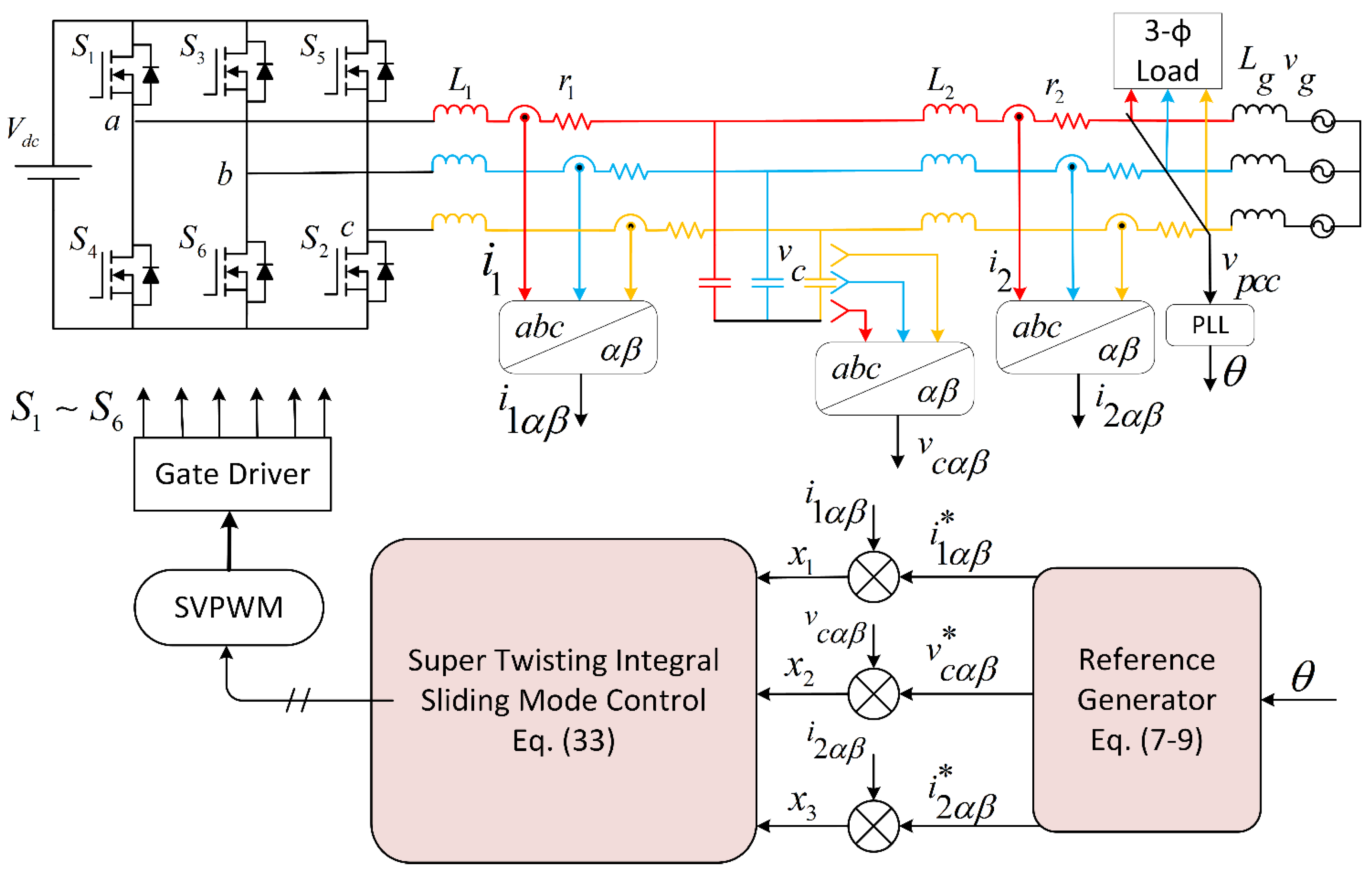
The utility grid is considered pure inductive, while the uncertainty in inductance is denoted by L g . The mathematical model of the GC-VSI system in the α β reference frame is derived as follows:
L 1 d i 1 α d t = v i α i 1 α r 1 v c α
L 1 d i 1 β d t = v i β i 1 β r 1 v c β
L 2 d i 2 α d t = v c α i 2 α r 2 v p c c α
L 2 d i 2 β d t = v c β i 2 β r 2 v p c c β
C d v c α d t = i 1 α i 2 α
C d v c β d t = i 1 β i 2 β
where v i p p = α β is the control input, inverter output current is i 1 = i 1 a , i 1 b , i 1 c , grid current i 2 = i 2 a , i 2 b , i 2 c , capacitor voltage v c = v c a , v c b , v c c , and v p c c = v p c c a , v p c c b , v p c c c are obtained using sensors. To inject current waveform in-phase with grid voltages, the reference for grid current, i 2 * , is obtained by utilizing the utility grid voltage phase angle extracted through the phase locked loop (PLL) in (7). Based on the system dynamics, inverter side reference current, i 1 * , and capacitor reference voltages, v c * , can be written as follows [22,23]:
i 2 p = I 2 sin ( ω t + θ )
v c p = L 2 i 2 p ˙ + v p c c + i 2 r 2 v c p = L 2 I 2 ω cos ( ω t + θ ) + v p c c + r 2 I 2 sin ( ω t + θ )
i 1 p = i 2 p + C v c p ˙ i 1 p = I 2 sin ( ω t + θ ) C L 2 I 2 ω 2 sin ( ω t + θ ) + C v p c c ˙ + r 2 I 2 ω cos ( ω t + θ )
The GC-VSI system in a stationary reference frame consisting of two independent α and β coordinates; therefore, in this study, the controller design procedure is carried out only on the α-axis, while the mathematical formulation for the β axis can be derived similarly as the α axis. In order to design the controller, error terms are introduced as the difference between desired and the actual values, while the integral action is applied on (12) to improve the reference tracking performance.
x 1 = i 1 i 1
x 2 = v c v c
x 3 = i 2 i 2
x 4 = i 2 i 2
Taking the time derivative of error terms in (10)–(13) gives:
x ˙ 1 = i 1 ˙ i 1 ˙
x ˙ 1 = r 1 L 1 x 1 1 L 1 x 2 + 1 L 1 v c * 1 L 1 v i + i 1 * ˙ + r 1 L 1 i 1 *
x ˙ 2 = v c ˙ v c ˙ = 1 C x 1 1 C x 3
x ˙ 3 = i 2 ˙ i 2 ˙ = 1 L 2 x 2 r 2 L 2 x 3
x ˙ 4 = i 2 i 2 = x 3

3. Super-Twisting Integral Sliding Mode Control Design

To begin with the design of a robust control algorithm, first we must select a sliding surface (SS) that can ensure global stability and minimum tracking error. There are various methods available for designing sliding surfaces from which the error-based sliding surface approach is applied because of its superior performance and simple design. The designed sliding surface function is comprised of inverter current error, grid current error, capacitor voltage error, and grid current reference integrator. Furthermore, to provide effective resonance damping and excellent tracking performance, the integral action is applied on the grid current error signal. The sum of the error terms defined in (10)–(13), chosen as a sliding surface, are given as:
S = α 1 x 1 + α 2 x 2 + α 3 x 3 + β x 4
S ˙ = α 1 x ˙ 1 + α 2 x ˙ 2 + α 3 x ˙ 3 + β x ˙ 4
where α 1 ,   α 2 ,   α 3 ,   a n d   β are the sliding coefficients responsible for rate of convergence of the trajectory. Now, putting the values of error differentials from (14)–(17) into (19), gives:
S ˙ = a 1 i 1 ˙ r 1 L 1 x 1 1 L 1 x 2 + r 1 L 1 i 1 + 1 L 1 v c 1 L 1 v i + a 2 + 1 C x 1 1 C x 3 + a 3 1 L 2 x 2 r 2 L 2 x 3 + β x 3
Now, to carry out the stability analysis of the proposed controller, let us consider the following Lyapunov function:
V = 1 2 S 2
V ˙ = S . S ˙
V ˙ = S [ a 1 i 1 ˙ a 1 r 1 L 1 x 1 a 1 L 1 x 2 + a 1 r 1 L 1 i 1 + a 1 L 1 v c a 1 L 1 v i + a 2 C x 1 a 2 C x 3 + a 3 L 2 x 2 a 3 r 2 L 2 x 3 + β x 3 ]
Next, to meet the Lyapunov stability criteria, which requires v ˙ 0 , let us take:
k 1 | S | ζ sign S = a 1 i 1 ˙ a 1 r 1 L 1 x 1 a 1 L 1 x 2 + a 1 r 1 L 1 i 1 + a 1 L 1 v c a 1 L 1 v i + a 2 C x 1 a 2 C x 3 + a 3 L 2 x 2 a 3 r 2 L 2 x 3 + β x 3
Here, k 1 S ζ sign(S) is the SMC reaching law, which is known as the power rate reaching law that increases the convergence rate of the trajectory when it is still in the reaching phase [32]. In addition, k 1 is a design parameter taken as a positive constant, ζ is usually a positive constant number whose value is between 0 and 1, S ζ ensures the convergence of the trajectories towards the sliding surface, and sign is the signum function given as follows:
Sign ( x ) = 1   i f     S < 0       0     i f   S = 0       1   i f   S > 0
After simplifying (22) for the control law v i , we get:
v e q = L 1 a 1 k 1 | S | ζ sign ( S ) + L 1 i ˙ 1 r 1 x 1 x 2 + r 1 i 1 + v c + L 1 C a 2 a 1 x 1 L 1 C a 2 a 1 x 3 + L 1 L 2 a 3 a 1 x 2 L 1 L 2 a 3 a 1 r 2 x 3 + L 1 a 1 β x 3
Now, putting (24) into (21), the Lyapunov stability analysis can be derived as follows:
V ˙ = S k 1 | S | ζ sign ( S )
Considering the properties of the Sign function defined in (23), one can further simplify (25) as:
V ˙ = S k 1 | S | ζ sign ( S ) 0
So, Lyapunov analysis proved that the designed controller is asymptotically stable and guarantees the finite time converge of all errors to zero. Next, the switching control ( u s w ) for super-twisting action is designed, which is composed of two terms:
u s w ( t ) = u 1 ˙ ( t ) + u 2 ( t )
u ˙ 1 ( t ) = u s w if | u s w | > 1 k 2 sign ( S ) if | u s w | 1
u 2 ( t ) = k 3 | S 0 | ρ sign ( S ) if | S | > S 0 k 3 | S | ρ sign ( S ) if | S | S 0
where S 0 is the boundary layer surrounding the sliding manifold. The finite time convergence of the trajectory approaching the sliding surface can be guaranteed by sufficient conditions, as given below.
k 3 > ψ Γ k 2 2 4 ψ Γ m a x ( k 3 + ψ ) Γ m i n 2 Γ m i n ( k 3 ψ ) 0 < ρ 0.5
where k 2 ,   k 3 ,   ρ are control gains and ψ ,   γ are constants. The super-twisting control equation can be simplified further when the systems under consideration are linearly dependent on the devised control [33], therefore, u s w becomes:
u s w ( t ) = k 2 | S | sign ( S ) + u 1 u 1 ˙ = k 3 sign ( S )
Furthermore, one can write (31) in compact form as follows:
u s w = k 2 | S | sign ( S ) k 3 sign ( S ) d ( τ )
The control law used in (32) is stable and its detailed proof is given in [34,35]. The final ST-ISMC control law becomes:
u S T I S M C = v e q + u s w
Finally, the control law derived in (33) for GC-VSI with an LCL filter is presented in structural diagram in Figure 3, and the controller parameter values are listed in Table 2. The parameter values are chosen by a trial-and-error-based approach.

4. Simulation Results

The proposed control scheme presented in Section 3 is implemented using MATLAB and Simulink platform in the α, β reference frame. In addition, the ST-ISMC controller performance is analyzed for filter parametric variations, grid inductance change, reference tracking, and utility grid harmonic components. In this study, a phase-locked loop is used to measure the grid voltage angle. The measured voltage angle is utilized to generate the sine wave at an angle similar to the grid voltage. This reference signal is subtracted from the grid current signal measured using the current sensor. The error signal is then fed to the ST-ISMC controller for reducing the steady state error and maintaining the system stability. Figure 4 shows that current delivered into the utility grid is in phase with the utility grid voltage, which ensures the maximum transfer of power. Furthermore, the fast Fourier transform (FFT) analysis of the grid current waveform is presented in Figure 5, which shows that a high-quality current is being injected into the grid. Next, ST-ISMC controller performance is analyzed for various scenarios; first, the controller behavior is mainly analyzed for grid harmonic components. The harmonic voltages are selected according to the European standard EN 50160. The 3rd, 5th, 7th, 9th, and 11th harmonic voltages are 5, 6, 5, 1.5 and 3.5 percent of the main harmonic component. The current waveform under grid voltage harmonics is depicted in Figure 6. Next, the reference tracking performance is examined with a step input change; Figure 7 depicts that the actual current tracks the reference current waveform within one cycle, which exhibits that the controller shows extraordinary transient performance and fast dynamic response.
Finally, to analyze the controller performance under the filter parameters variation, the value of the filtering capacitor, VSI side, and grid side inductors varied by −33% from the nominal value, for which the current waveforms in Figure 8, Figure 9 and Figure 10 clearly shows that the grid current maintains high quality and THD value is much lower than the upper bound from the grid operators. In the GC-VSI system to consider the temperature variations, aging effects, and system parametric variation value when multiple inverters are connected in parallel, a 33% variation of L g is considered. It can be observed in Figure 11 that controller performance is still accurate and satisfies the THD limit for grid connections, even in worse conditions. The dynamic analysis of controller performance shows that it can effectively damp the resonance and maintain the stability, even under extreme operating conditions.

5. Experimental Results

To verify the performance of the proposed control technique, a 1 kW prototype system is fabricated and tested to prove the simulated results. A three-phase VSI is assembled from three CM150DU-24FA Mitsubishi Insulated-gate bipolar transistor (IGBT) modules, and a DSPTMS320F28335 controller is used for control purposes. In addition, LA 55-P current sensors and LV 25-P voltage sensors by LEM are used for current and voltage measurement, respectively. To obtain clean ac output, current space vector modulation is implemented; the inverter output voltages without filtering are shown in Figure 12. The three-phase output current delivered to the grid under nominal conditions is shown in Figure 13. The result for controller performance under filter parametric variation presented in Figure 14 proves the effectiveness of the controller. In Figure 15, to depict the controller performance in the presence of utility grid disturbance, an external inductor is attached, which shows the robustness of the controller.
Figure 16 shows the output current THD under different utility harmonics. It further supports the claim of robustness of the proposed controller under strong harmonics.

6. Conclusions

This article devised a super-twisting integral sliding mode control strategy for three-phase grid-connected inverter application for the first time. The designed nonlinear controller in a stationary α ,   β reference frame guarantees the asymptotic stability of the desired system and injects pure sinusoidal current into the grid. At the same time, it does not require any Park transformation associated with traditional controllers, which reduces the computation of the digital signal processor. MATLAB and Simulink platforms are used to carry out simulation of the entire system. Furthermore, the robustness of the controller is analyzed in the presence of −33% filter parametric drift, 33% grid impedance variations, and grid harmonics of the 3rd-, 5th-, 7th-, 9th-, and 11th-order. The ST-ISMC controller is designed without the incorporation of any external damping, physically or virtually. This prevents the power loss and sensors cost required for passive and active damping, respectively. Finally, a prototype system is designed and tested to validate the proposed controller performance. The current waveform shows that the proposed controller delivers high-quality current to the grid and ensures excellent reference tracking performance.

Author Contributions

Conceptualization, A.S.; Methodology, A.S. and H.A.A.; Investigation, A.S. and H.A.A.; Writing—original draft, A.S.; Writing—review & editing, M.J., Q.A., A.A.K. and H.A.; Supervision, M.J., S.G. and H.A.; Project administration, M.J., S.G. and Q.A. All authors have read and agreed to the published version of the manuscript.

Funding

This research received no external funding.

Institutional Review Board Statement

Not applicable.

Informed Consent Statement

Not applicable.

Data Availability Statement

Not applicable.

Conflicts of Interest

The authors declare no conflict of interest.

Abbreviations

The abbreviations used in the technical note are explained below:
V d c Dc supply voltage
V g Grid supply voltage
i 1 Inverter output current
i 2 Grid output current
V c Voltage across filter capacitor
CFilter capacitor
L 1 1st Inductor of LCL filter
L 2 2nd Inductor of LCL filter
L g Grid impedance
α 1 , α 2 , α 3 , β Sliding surface coefficients
K 1 SMC reaching law design parameter
K 2 , K 3 ,   ζ Controller gains
F s Switching frequency
Ω Grid frequency
v e q Equivalent control
u s w Super-twisting switching action
u S T I S M C Super-twisting Integral Sliding Mode Law

References

  1. Kouro, S.; Leon, J.I.; Vinnikov, D.; Franquelo, L.G. Grid connected photovoltaic systems: An overview of recent research and emerging pv converter technology. IEEE Ind. Electron. Mag. 2015, 9, 47–61. [Google Scholar] [CrossRef]
  2. Lin, Z.; Ruan, X.; Wu, L.; Zhang, H.; Li, W. Multi resonant component-based grid-voltage-weighted feedforward scheme for grid- connected inverter to suppress the injected grid current harmonics under weak grid. IEEE Trans. Power Electron. 2020, 35, 9784–9793. [Google Scholar] [CrossRef]
  3. Jamil, M.; Hussain, B.; Abu-Sara, M.; Boltryk, R.; Sharkh, S. Microgrid power electronic converters: State of the art and future challenges. In Proceedings of the IEEE 44th International Universities Power Engineering Conference (UPEC), Glasgow, UK, 1–4 September 2009; pp. 1–5. [Google Scholar]
  4. Bai, Z.; Ma, H.; Xu, D.; Wu, B.; Fang, Y.; Yao, Y. Resonance damping and harmonic suppression for grid-connected current-source converter. IEEE Trans. Ind. Electron. 2013, 61, 3146–3154. [Google Scholar] [CrossRef]
  5. Sharma, H.R.; Suryawanshi, H.M.; Chaturvedi, P.; Govind, D. Implementation of Passive Damping Technique in LCL Filter for Three-Phase Grid Connected Inverter. In Proceedings of the 2022 IEEE 2nd International Conference on Sustainable Energy and Future Electric Transportation (SeFeT), Hyderabad, India, 4–6 August 2022; pp. 1–6. [Google Scholar] [CrossRef]
  6. Wu, W.; He, Y.; Tang, T.; Blaabjerg, F. A New Design Method for the Passive Damped LCL and LLCL Filter-Based Single-Phase Grid-Tied Inverter. IEEE Trans. Ind. Electron. 2013, 60, 4339–4350. [Google Scholar] [CrossRef]
  7. Sgrò, D.; Souza, S.A.; Tofoli, F.L.; Leão, R.P.S. An integrated design approach of LCL filters based on nonlinear inductors for grid-connected inverter applications. Electr. Power Syst. Res. 2020, 186, 106389. [Google Scholar] [CrossRef]
  8. Wu, W.; Liu, Y.; He, Y.; Chung, H.S.-H.; Liserre, M.; Blaabjerg, F. Damping Methods for Resonances Caused by LCL-Filter-Based Current-Controlled Grid-Tied Power Inverters: An Overview. IEEE Trans. Ind. Electron. 2017, 64, 7402–7413. [Google Scholar] [CrossRef] [Green Version]
  9. Avila, V.H.; Leite, V. Control of grid-connected inverter output current: A practical review. In Proceedings of the IEEE 9th International Conference on Renewable Energy Research and Application (ICRERA), Glasgow, UK, 27–30 September 2020; pp. 232–235. [Google Scholar]
  10. Jamil, M.; Waris, A.; Gilani, S.O.; Khawaja, B.A.; Khan, M.N.; Raza, A. Design of robust higher-order repetitive controller using phase lead compensator. IEEE Access 2020, 8, 30603–30614. [Google Scholar] [CrossRef]
  11. Husev, O.; Roncero-Clemente, C.; Makovenko, E.; Pimentel, S.P.; Vinnikov, D.; Martins, J. Optimization and implementation of the proportional-resonant controller for grid-connected inverter with significant computation delay. IEEE Trans. Ind. Electron. 2019, 67, 1201–1211. [Google Scholar] [CrossRef]
  12. Qu, B.; Hong, X.-Y.; Yao, W.-X.; Lu, Z.-Y.; Guerrero, J.M. An optimized deadbeat control scheme using fuzzy control in three phase voltage source pwm rectifier. In Proceedings of the IEEE Twenty-Fourth Annual Applied Power Electronics Conference and Exposition, Washington, DC, USA, 15–19 February 2009; pp. 1215–1219. [Google Scholar]
  13. Teodorescu, R.; Blaabjerg, F.; Liserre, M.; Loh, P.C. Proportional- resonant controllers and filters for grid-connected voltage-source con- verters. IEE Proc.-Electr. Power Appl. 2006, 153, 750–762. [Google Scholar] [CrossRef]
  14. Liu, Q.; Caldognetto, T.; Buso, S. Review and comparison of grid- tied inverter controllers in microgrids. IEEE Trans. Power Electron. 2019, 35, 7624–7639. [Google Scholar] [CrossRef]
  15. Alali, M.A.E.; Shtessel, Y.B.; Barbot, J.-P. Grid-Connected Shunt Active LCL Control via Continuous Sliding Modes. IEEE/ASME Trans. Mechatron. 2019, 24, 729–740. [Google Scholar] [CrossRef]
  16. Roy, T.; Mahmud, M.; Hossain, M.; Oo, A. Nonlinear backstepping controller design for sharing active and reactive power in three-phase grid-connected photovoltaic systems. In Proceedings of the IEEE Australasian Universities Power Engineering Conference (AUPEC), Wollongong, Australia, 27–30 September 2015. [Google Scholar]
  17. Meza, C.; Biel, D.; Jeltsema, D.; Scherpen, J.M. Lyapunov-based control scheme for single-phase grid-connected pv central inverters. IEEE Trans. Control Syst. Technol. 2011, 20, 520–529. [Google Scholar] [CrossRef]
  18. Abrishamifar, A.; Ahmad, A.; Mohamadian, M. Fixed switching frequency sliding mode control for single-phase unipolar inverters. IEEE Trans. Power Electron. 2011, 27, 2507–2514. [Google Scholar] [CrossRef]
  19. Levant, A. Universal single-input-single-output (siso) sliding-mode controllers with finite-time convergence. IEEE Trans. Auto. Control 2001, 46, 1447–1451. [Google Scholar] [CrossRef] [Green Version]
  20. Emel’yanov, S.; Korovin, S.; Levantovskii, L. Higher-order sliding modes in binary control systems. Sov. Phys. Dokl. 1986, 31, 291. [Google Scholar]
  21. Li, H.; Wu, W.; Huang, M.; Chung, H.S.H.; Liserre, M.; Blaabjerg, F. Design of pwm-smc controller using linearized model for grid- connected inverter with lcl filter. IEEE Trans. Power Electron. 2020, 35, 12773–12786. [Google Scholar] [CrossRef]
  22. Hao, X.; Yang, X.; Liu, T.; Huang, L.; Chen, W. A sliding-mode controller with multiresonant sliding surface for single-phase grid- connected vsi with an lcl filter. IEEE Trans. Power Electron. 2012, 28, 2259–2268. [Google Scholar] [CrossRef]
  23. Liu, J.; Shen, X.; Alcaide, A.M.; Yin, Y.; Leon, J.I.; Vazquez, S.; Wu, L.; Franquelo, L.G. Sliding mode control of grid-connected neutral-point- clamped converters via high-gain observer. IEEE Trans. Ind. Electron. 2021, 69, 4010–4021. [Google Scholar] [CrossRef]
  24. Zeb, K.; Busarello, T.D.C.; Islam, S.U.; Uddin, W.; Raghavendra, K.V.G.; Khan, M.A.; Kim, H.-J. Design of super twisting sliding mode controller for a three-phase grid-connected photovoltaic system under normal and abnormal conditions. Energies 2020, 13, 3773. [Google Scholar] [CrossRef]
  25. Kale, M.; Karabacak, M.; Kruschel, W.; Kilic, F.; Zacharias, P. Chattering free robust control of lcl filter based shunt active power filter using adaptive second order sliding mode and resonant controllers. Int. J. Electr. Power Energy Syst. 2016, 76, 174–184. [Google Scholar] [CrossRef]
  26. Hou, Q.; Ding, S.; Yu, X. Composite super-twisting sliding mode control design for pmsm speed regulation problem based on a novel disturbance observer. IEEE Trans. Energy Convers. 2020, 36, 2591–2599. [Google Scholar] [CrossRef]
  27. Derafa, L.; Benallegue, A.; Fridman, L. Super twisting control algorithm for the attitude tracking of a four rotors uav. J. Frankl. Inst. 2012, 349, 685–699. [Google Scholar] [CrossRef]
  28. Yeam, T.-I.; Lee, D.-C. Design of sliding-mode speed controller with active damping control for single-inverter dual-pmsm drive systems. IEEE Trans. Power Electron. 2020, 36, 5794–5801. [Google Scholar] [CrossRef]
  29. Komurcugil, H.; Biricik, S.; Bayhan, S.; Zhang, Z. Sliding mode control: Overview of its applications in power converters. IEEE Ind. Electron. Mag. 2021, 15, 40–49. [Google Scholar] [CrossRef]
  30. Chalanga, A.; Kamal, S.; Fridman, L.M.; Bandyopadhyay, B.; Moreno, J.A. Implementation of super-twisting control: Super-twisting and higher order sliding-mode observer-based approaches. IEEE Trans. Ind. Electron. 2016, 63, 3677–3685. [Google Scholar] [CrossRef]
  31. Xia, J.; Guo, Y.; Zhang, X.; Jatskevich, J.; Amiri, N. Robust control strategy design for single-phase grid-connected converters under system perturbations. IEEE Trans. Ind. Electron. 2019, 66, 8892–8901. [Google Scholar] [CrossRef]
  32. Gao, W.; Hung, J.C. Variable structure control of nonlinear systems: A new approach. IEEE Trans. Ind. Electron. 1993, 40, 45–55. [Google Scholar]
  33. Fridman, L.; Levant, A. Higher order sliding modes. Sliding Mode Control. Eng. 2002, 11, 53–102. [Google Scholar]
  34. Seeber, R.; Horn, M. Stability proof for a well-established super- twisting parameter setting. Automatica 2017, 84, 241–243. [Google Scholar] [CrossRef]
  35. Shtessel, Y.; Edwards, C.; Fridman, L.; Levant, A. Sliding Mode Control and Observation; Springer: New York, NY, USA, 2014. [Google Scholar]
Figure 1. Graphical illustration of SMC chattering phenomenon.
Energies 15 09428 g001
Figure 2. Three-phase GC-VSI system with the STISMC controller.
Energies 15 09428 g002
Figure 3. ST-ISMC Controller Implementation diagram.
Energies 15 09428 g003
Figure 4. Grid current and voltage waveform.
Energies 15 09428 g004
Figure 5. FFT analysis for grid current waveform.
Energies 15 09428 g005
Figure 6. ST-ISMC Controller current waveform under grid harmonic.
Energies 15 09428 g006
Figure 7. ST-ISMC controller reference current tracking waveform.
Energies 15 09428 g007
Figure 8. Waveform for current injected into the grid under L 1 variation.
Energies 15 09428 g008
Figure 9. Waveform for current injected into the grid under L 2 variation.
Energies 15 09428 g009
Figure 10. Waveform for current injected into the grid with capacitance variation.
Energies 15 09428 g010
Figure 11. Performance with variation of grid impedance.
Energies 15 09428 g011
Figure 12. Three-phase inverter output voltages.
Energies 15 09428 g012
Figure 13. Grid current waveform under nominal condition.
Energies 15 09428 g013
Figure 14. Grid Current waveform under filter parameter variation.
Energies 15 09428 g014
Figure 15. Grid current waveform in the presence of disturbance.
Energies 15 09428 g015
Figure 16. THD of output current in the presence/absence of ST–ISMC control.
Energies 15 09428 g016
Table 1. System Parameter Description.
DescriptionSymbolValue
DC supply voltage V d c 350 V
VSI side Inductor L 1 1.2 mH
CapacitanceC6 µF
Grid side Inductor L 2 1.2 mH
Resistance of Inductor r 1 ,     r 2 0.2 Ω
Grid Voltage V g 110 (RMS)
Switching frequency F s 12 KHz
Table 2. ST-ISMC Controller Gain.
ParameterValue
α1, α2, α31.5
Β200
k113.5
k213.5
k35 × 104
  Ζ 0.5
α1, α2, α31.5
Publisher’s Note: MDPI stays neutral with regard to jurisdictional claims in published maps and institutional affiliations.

