Review

A Review on Up-to-Date Gearbox Technologies and Maintenance of Tidal Current Energy Converters

Department of Mechanical Engineering, University of Maryland, Baltimore County, Baltimore, MD 21250, USA
*
Author to whom correspondence should be addressed.
Energies 2022, 15(23), 9236; https://doi.org/10.3390/en15239236
Submission received: 30 October 2022 / Revised: 28 November 2022 / Accepted: 30 November 2022 / Published: 6 December 2022

Abstract

:
This paper presents a review-based comparative study of state-of-the-art technologies, technical challenges and research barriers, and development trends of gearboxes used in tidal current energy converters (TCECs). Currently, the development of commercial projects using TCECs is still in the demonstration phase. While many drivetrain designs and configurations of TCECs inherit from those of wind turbines, different operational constraints, e.g., high-torque and low-speed conditions, make TCECs potentially suffer from high failure rates in harsh deep-sea environments. Evidence of these potentially high failure rates highlights the need for adopting the most resilient drivetrain options with a high degree of maintainability. The gearbox option is a critical issue that needs to be addressed for the choice of the drivetrain configuration due to its longest downtime per failure among all drivetrain components of TCECs. The main purpose of this study is to review current gearbox technologies of TCECs with advantages and disadvantages as well as to identify future technical challenges and research barriers. Gearbox maintenance is also a focal point in this study. We present a discussion of the operation phase to highlight operational maintenance methods currently used in the tidal energy industry. This study will, therefore, address the critical issue by proposing a review-based gearbox option comparison and discussing potential solutions to reduce operation and maintenance costs of gearboxes of TCECs.

1. Introduction

Oceans offer a massive resource of potential renewable energy in the form of marine and tidal currents, sea waves, sea level ranges, thermal gradients, and salinity gradients [1]. The development of marine renewable energies provides a cost-effective means to reduce the usage of fossil fuels and represents a major opportunity to reduce greenhouse gas emissions [2]. Tidal energy is the potential energy and the kinetic energy of tides that are converted from the potential energy between the earth and the sun and between the earth and the moon [3,4]. According to the current tidal data reported, the globe potential harvestable tidal energy is around 1200 TWh per year [5]. Compared with existing tidal barrage systems, e.g., the La Rance tidal power station in France and the Sihwa Lake power station in South Korea, most tidal current energy technologies are still in research and development (R&D) and demonstration stages [5,6]. However, several investigations have confirmed that tidal current energy technologies have great commercialization potential as a sustainable clean energy source for power generation with fewer harmful environmental impacts as opposed to tidal barrage technologies [7,8,9,10].
Tidal current energy converters (TCECs) are developed to convert the hydrokinetic energy of tidal flows into the electrical energy. A drivetrain of a TCEC converts the kinetic energy of a turbine to the electrical energy of a generator, which is the entire power conversion system from the main bearing to the generator. A TCEC harnesses the maximum amount of the tidal current energy when it operates at an optimal turbine speed, which is determined by tidal speeds. Since tidal speeds are variable with gravitational forces of the sun and the moon on the earth, the optimal turbine speed of the TCEC also changes with tidal speeds. According to prior studies [11,12,13], variable-speed operation of the turbine has a higher energy production compared to a turbine operating with constant tidal speeds. In order to generate alternating current (AC) power with a fixed phase and frequency to the grid, variable-frequency power generated by a permanent-magnet generator (PMG) has to be converted from AC to direct current (DC) and back to AC by power electronics, i.e., a power converter and an inverter, which are expensive and failure-prone, requires costly equipment repair, and also tends to make other components of the TCEC to prematurely fail [14,15,16]. However, the power quality of the TCEC can be reduced due to the harmonic distortion of AC introduced by these power electronics and their power losses. This increases the interest in variable speed systems using a different technology. Some variable-speed gearboxes are designed to be incorporated in TCEC drivetrains to control speed ratios between turbine speeds and generator speeds. A variety of drivetrain technologies of TCECs are available. Each of these technologies has pros and cons in terms of design principle, cost, size, manufacturing, material, efficiency, reliability, and operation and maintenance (O&M) [17,18,19,20].
Drivetrain designs and option choices of TCECs affect their operation performance, reliability, total cost, and O&M [21]. Due to technology similarities between wind turbine systems and TCECs, most drivetrain designs of TCECs follow current wind turbine drivetrain designs with planetary gearboxes and PMGs [22]. While similar drivetrain designs make it possible to evaluate the reliability and O&M of drivetrains of TCECs based on failure and condition monitoring data of wind turbine systems, there are insufficient experience and information on O&M of TCECs in harsh deep-sea environments [23,24]. Generally, the gearbox is the key component of a drivetrain of the TCEC that transmits the most enormous load and entails high O&M costs since its maintenance requires external large-tonnage cranes. A systematic review on further challenges of gearboxes of TCECs is needed to improve its reliability and compactness, and reduce maintenance costs.
With the application of different condition monitoring systems (CMSs) in all tidal energy industries, new opportunities for drivetrain condition monitoring have arisen in the operation phase, including oil condition monitoring (OCM), vibration-based condition monitoring, supervisory control and data acquisition (SCADA), and acoustic emission condition monitoring systems [25,26,27,28]. OCM is a common solution to identify gearbox faults, evaluate operation conditions, and define oil maintenance intervals [29,30]. According to the rated power and the size of the gearbox of a TCEC, its oil quantity is in the range of 200 to 800 L. Hence, extending oil maintenance intervals of a gearbox to the maximum life span of gearbox oils can reduce O&M costs of TCECs. OCM is mainly performed by using oil sampling or sensors that measure some parameters, e.g., wear particle counting and oil contaminant elements [31]. Other studies of OCM focused on sensor validation of oil analysis methods to identify gearbox faults based on valid data on additive depletion and oil degradation [32] due to oxidation, oil contamination, temperature, and viscosity changes [33]. In addition, several OCM methods of gearboxes based on multivariate oil analysis methods, e.g., fluorescence spectroscopy, and oil viscosity measurements were developed to improve analysis accuracy and measurement sensitivity of oil-based CMSs of gearboxes [34,35,36,37,38]. While OCM is a common gearbox condition monitoring method in the tidal energy industry, there are limited published valid data on the additive depletion and oil degradation of gearboxes of TCECs. Due to the core role of OCM in gearbox operation condition monitoring, this review focuses on presenting valid information about the current gearbox oil analysis process in TCECs.
This review aims to summarize the state-of-the-art gearbox technologies of TCECs, address the main gearbox issue of TCECs by proposing a review-based drivetrain option comparison, and synthesize the information of O&M procedures of condition monitoring of gearbox oils. The remaining parts of the paper are organized as follows: some design trends and layouts of drivetrains of TCECs are introduced in Section 2. The status and development of gearbox technologies are presented in Section 3. Gearbox maintenance procedures and methods are presented in Section 4. Discussion of future work of gearbox technologies and maintenance of TCECs is given in Section 5. Conclusions from this study are presented in Section 6.

2. Layout and Design Principles of Power Conversion Chains of TCECs

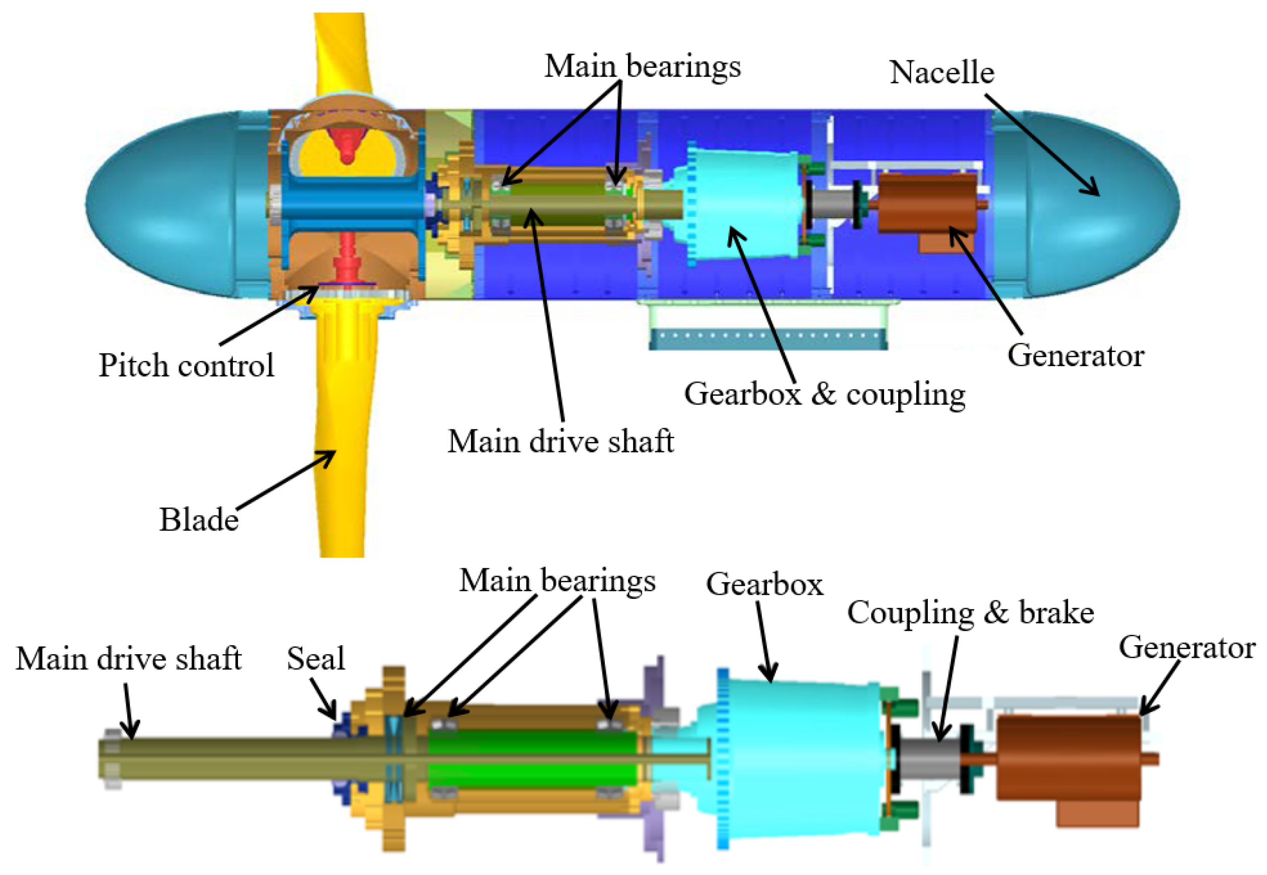
2.1. Layout of Power Conversion Chains

A TCEC consists of a number of components to convert the tidal current energy into the electrical energy. A power conversion chain of the TCEC includes a turbine and pitch control system and a drivetrain system [39]. The layout of a drivetrain of the TCEC is shown in Figure 1. The turbine and pitch control system harvests the kinetic energy from tidal flows, which includes turbine blades, motors for pitch control, gears, slip rings, and some seals. The drivetrain system converts the kinetic energy into the electrical energy, which includes a main drive shaft, main bearings, a gearbox, a coupling, a brake, and a generator.
The turbine size and pitch control design of the TCEC are determined by local hydrological and geographical conditions. Currently, TCECs require a tidal speed in excess of 2.25 m/s [40,41,42] and a water depth between 25 and 50 m to harvest sufficient power with a large swept area of turbine blades and a high tidal speed [43,44]. Sea regions with such high tidal speeds are sparse and generally caused by topographic flow enhancement, e.g., phase difference-driven flows through straits [45,46]. The design principle of the drivetrain system of the TCEC depends on the power and the torque produced by the turbine.
Figure 1. Schematic of a power conversion chain of the TCEC [47].
Energies 15 09236 g001

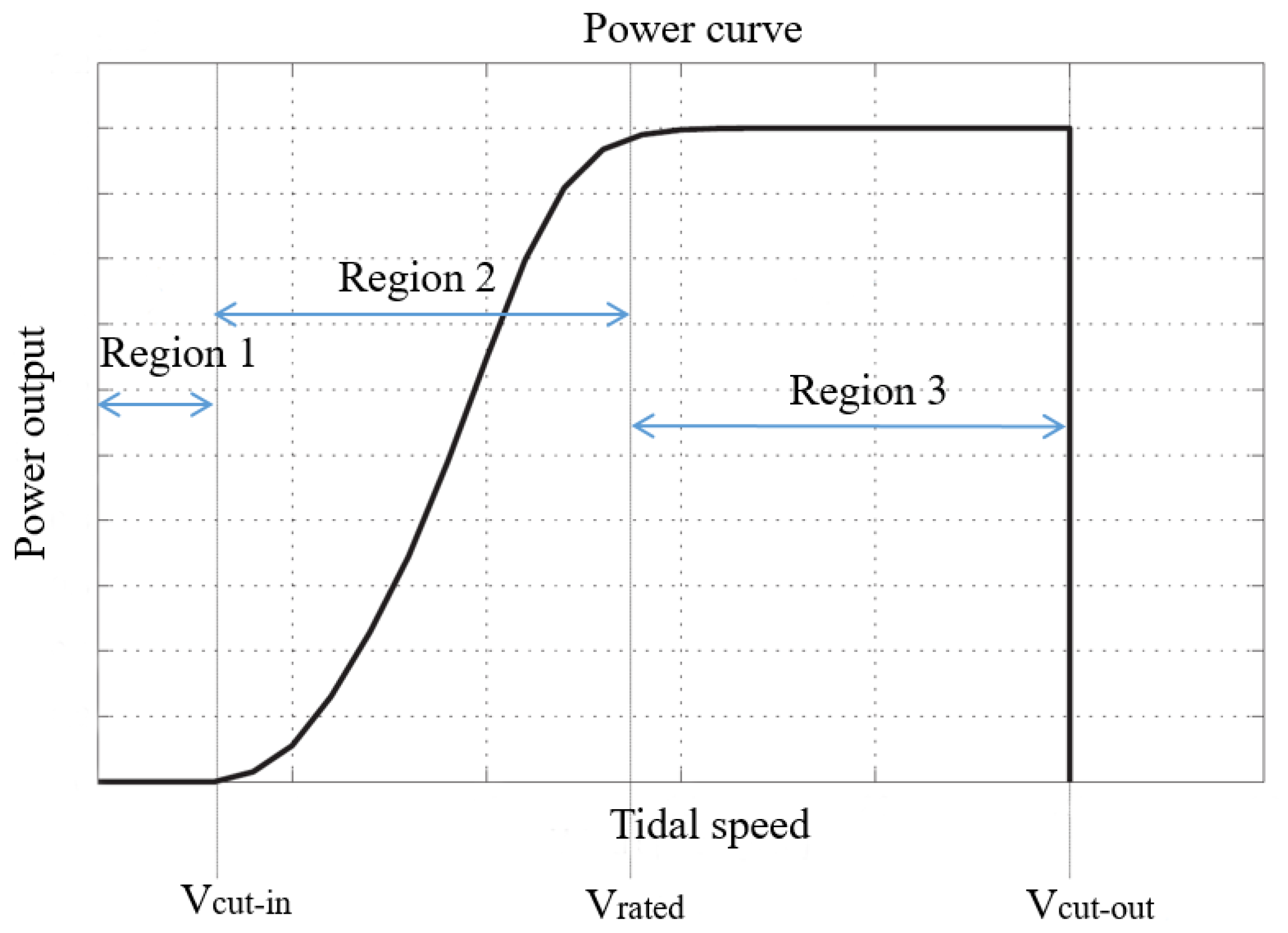
2.2. Power and Torque in Power Conversion Chains

The basic principle of tidal current energy harvesting is mainly based on Betz’s law [48]. It shows that the kinetic energy harvestable from a fluid flow passing through a given cross-sectional area is restricted to a certain fixed proportion of the energy contained in the fluid flow, which is the power coefficient C p . The maximum power coefficient according to Betz’s law is
C p   max = 16 27 = 0.593 .
This maximum power coefficient C p   max is the theoretical maximum, which is known as Betz’s limit. The power coefficient C p mainly depends on the ratio of the rotation speed of the tips of turbine blades and the tidal speed, which is known as the tip-speed ratio, defined as
λ = ω t R v t i d a l ,
where ω t is the turbine rotation speed, R is the rotor radius, and v t i d a l is the tidal speed. The maximum tidal current energy of the TCEC that can be harvested from tidal flows exists when its turbine is operated at the optimal tip-speed ratio. The harvested tidal current energy has a cubic relation with the tidal speed [49]:
P r = 1 2 ρ A C p v t i d a l 3 ,
where ρ is the density of seawater and A is the swept area of the turbine.
The operating regime of a TCEC is divided into three regions [44], as shown in Figure 2. Region 1 is the low tidal speed region, where the TCEC cannot generate any power and is disconnected from the grid. If the TCEC is connected to the grid at a tidal speed in Region 1, the tidal turbine is driven by the generator without any power generation but with power consumption. Region 2 is the speed range between the cut-in speed v c u t i n and the rated speed v r a t e d of the TCEC. Region 3 is the region from the rated speed v r a t e d to the cut-out speed v c u t o u t . The harvested energy by the TCEC is hydrodynamically and mechanically restricted in Region 3 so that the TCEC can avoid overloads and mechanical failures.
In these three regions, the operational torque of the drivetrain is an important parameter of the TCEC. The operational torque of the drivetrain is
T r = 1 2 ρ A R C Q v t i d a l 3 ,
where C Q is the torque coefficient that is C Q = C p / λ [50]. The power and torque produced by the turbine can be determined by Equations (3) and (4), respectively.

2.3. Drivetrain Technologies

Since TCECs are operated in deep-sea environments, all drivetrain components must be housed within a watertight nacelle to maintain overall system seawater tightness. The watertight nacelle design of the TCEC eliminates the need to individually seal each component of the drivetrain in a watertight and seaworthy environment. A compact and lightweight drivetrain is the most cost-effective option for large TCECs since it can reduce the weights of their nacelles, towers, and foundations and lower their costs [51,52]. To reduce the weights of nacelles, there has been a development trend toward increasing mechanical integration of the main drive shaft, main bearings, the gearbox, and the generator [53,54,55].
(1) Main drive shaft. The drivetrain design of the TCEC starts with the determination of design specifications of the main drive shaft. The main drive shaft has to be subjected to the operational torque T r in Equation (4) produced by the turbine, and accommodate auxiliary equipment. It is desirable to minimize the size of the main drive shaft while keeping its performance based on a safety factor, which is greater than 1.1, under the maximum operational torque to reduce its weight.
(2) Main bearings and seals. Main bearings and seals are designed with the intent of supporting the operational torque T r and the turbine thrust, the main drive shaft, and connected components, while withstanding subsea unsteady loads, and protecting the balance of the drivetrain from seawater, which can propagate into the drivetrain from the turbine rotation plane. A commercially standard bearing and seal package assembly can be selected with the purpose to minimize maintenance and maximize the main bearing life.
(3) Gearbox. The gearbox can transmit the operational torque T r produced by the turbine to the generator. Generally, turbine blades of TCECs have a rotation speed of 7 rpm, which is lower than that of wind turbines, which is from 10 to 30 rpm [56,57]. Since most PMGs most efficiently operate at rotation speeds from hundreds of rpm to 1850 rpm [58], the gearbox must have a speed ratio of 1:100 to 1:120. Low-speed and high-torque operation conditions of TCECs should be carefully considered in their gearbox design and selection processes.
(4) Generator. Generally, PMGs are selected for current TCECs due to high efficiency and reliability, high power density, low rotor temperature, and high synchronous operation flexibility [59,60]. Based on these advantages, PMGs can operate at base frequencies other than 50 Hz or 60 Hz. While an inverter must be added to the drivetrain to adjust its output frequency to 50 Hz or 60 Hz for grid connection, the advantages of PMGs outweigh the increase in complexity of an electrical conditioning system [61,62].

3. Gearbox Technologies

Gearboxes are widely used in automobile, aerospace, energy, and process industries and are considered indispensable [63]. Tidal flows always have very low speeds that rarely exceed 5 m/s. Lower tidal speeds result in lower turbine rotation speeds. Therefore, if conventional generators are used to produce electricity, gearboxes are necessary to achieve higher rotor speeds [64]. Currently, most drivetrain technologies that have been suggested for tidal current energy harvesting are reminiscent of those used for wind turbine applications. There are two drivetrain design strategies for TCECs, i.e., geared and direct-drive drivetrains [21]. In most geared drivetrains of TCECs, their main drive shafts and generators are directly coupled via mechanical gearboxes or indirectly coupled via hydraulic transmissions [21,65,66,67,68,69]. Generator options for geared drivetrains can be induction generators and PMGs. Direct-drive drivetrains are developed with the purpose of minimizing maintenance issues and O&M costs by removing gearboxes and using unconventional low-speed and high-diameter permanent-magnet synchronous generators. In a direct drive train system, a permanent-magnet synchronous generator is directly driven by a turbine hub of a TCEC [70]. Some state-of-the-art gearbox technologies and direct-drive drivetrains are discussed in this section.

3.1. Planetary and Multi-Stage Gearboxes

Current TCECs try to harvest more tidal energy by using PMGs and large planetary gearboxes [71]. In a 2 MW TCEC, its planetary gearbox typically has a speed ratio of around 1:150. The gearbox with that speed ratio can be designed by using three or four gear sets based on a combination of planetary and multi-stage gear sets [50,71], as shown in Figure 3. The efficiency of the drivetrain is dependent on the number of gear sets and the efficiency of each gear set. Generally, multi-stage gear sets have an efficiency of around 98%, while the efficiency of planetary gear sets even reaches 99% [72,73]. The advantages of using multi-stage gear sets are their wide availability and low costs. On the other hand, planetary gear sets are slightly more efficient and can yield higher speed ratios in compact spaces. A gear pair in a multi-stage gear set can have a speed ratio of up to 1:5, while a gear pair in a planetary gear set is built with a speed ratio of up to 1:12. Furthermore, the operational torque T r is better distributed through more meshing gear pairs. This gives the planetary gear set a higher torque capability. Finally, bearing forces in the planetary gear set are smaller than those in multi-stage gear sets. For megawatt TCECs, costs of gearboxes are significantly reduced when using planetary gear sets due to their small sizes and masses. Planetary gear sets are preferable for megawatt TCECs. A limitation of planetary and multi-stage gearboxes is that most of their speed ratios are constant and they cannot eliminate speed fluctuations caused by variable tidal speeds and turbulence. By considering that gearboxes serve as increasers in drivetrains, they can enlarge these speed fluctuations and have large impacts on generators, which can cause generator failures.
Some commercially developed planetary gearboxes of TCECs are shown in Figure 4. Tidal Generation Ltd (TGL) developed a 500 kW tidal current turbine, i.e., Deepgen, using a 500 kW planetary gearbox and an induction generator, which was successfully deployed and connected to the grid in 2010. This 500 kW planetary gearbox had a speed ratio of 1:100.5, as shown in Figure 4a [74]. Marine Current Turbine (MCT) developed a dual horizontal-axis TCEC system i.e., SeaGen [75]. Each turbine of the SeaGen system was a 600 kW two-blade turbine that was coupled with a 650 kW planetary gearbox, which had a speed ratio of 1:110, as shown in Figure 4b. Andritz Hydro developed a 1.5 MW horizontal-axis TCEC, i.e., MeyGen [76,77]. Its nacelle included a 1.5 MW two-stage planetary gearbox, as shown in Figure 4c, and a PMG that could operate with a high harvesting efficiency over a wide tidal speed range. Orbital Marine Power Ltd (Orbital) developed a 2 MW floating TCEC, i.e., SR2-2000, using a Superposition Gear (SPG) system, which consisted of two planetary gear sets mounted on a parallel shaft [78,79], as shown in Figure 4d. The SPG system enables a variable speed ratio in the range of 1:125–1:79 and maintains a constant output speed.

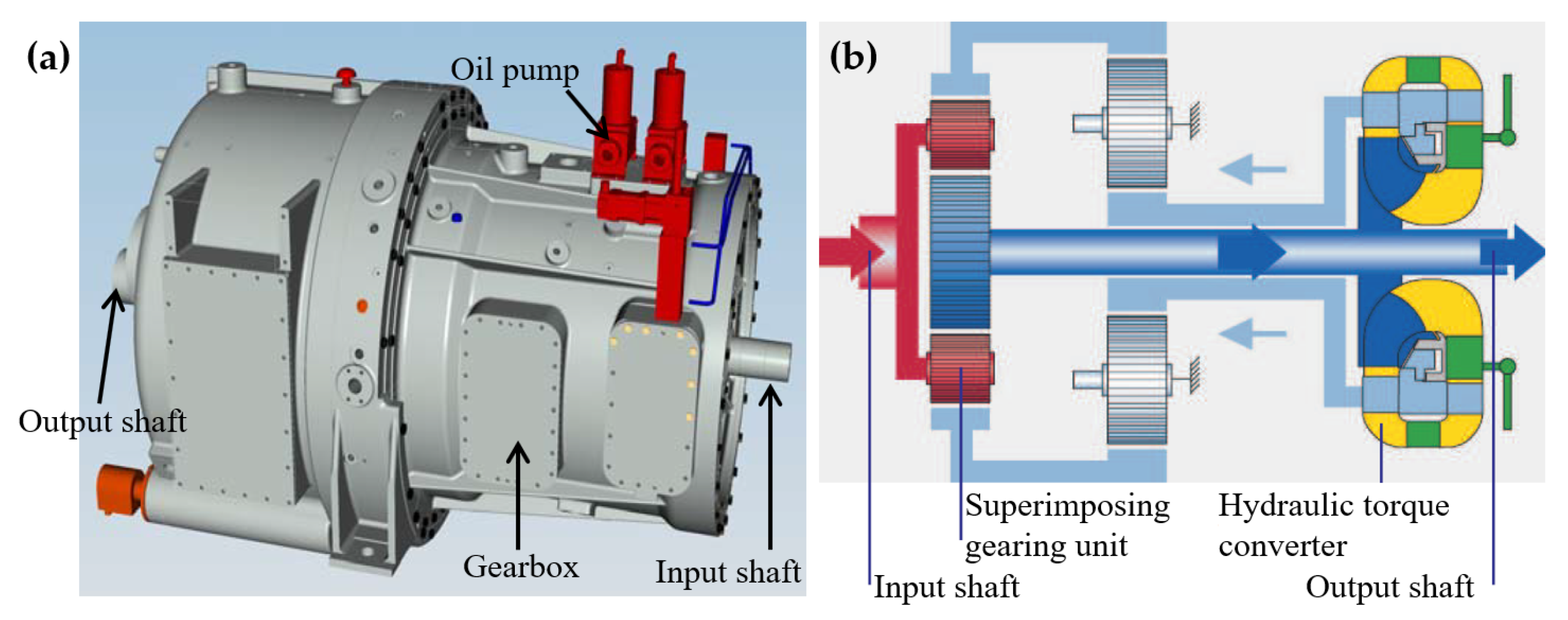
3.2. Hydraulic Transmissions

Hydraulic transmissions were developed with hydraulic pumps and several fixed- or variable-displacement hydraulic motors [80,81]. Hydraulic pumps converted the kinetic energy of tidal turbines into the potential energy of the pressurized fluid. Hydraulic motors converted the potential energy of the pressurized fluid back into the kinetic energy of generator shafts [69]. A hydraulic transmission system of a TCEC was developed based on the digital displacement technology that converted variable turbine rotation speeds into a constant generator shaft speed [68]. A hydraulic–mechanical hybrid transmission of TCECs for maximum power point tracking (MPPT) using a planetary gear set as a power split device has also been developed [82]. In this hydraulic–mechanical hybrid transmission, the hydraulic pump displacement control was designed to vary its rotation speed to realize MPPT, and harvested tidal power could be stabilized via a hydraulic system. A hydraulic accumulator was designed for a hybrid wind–tidal turbine [83]. A hybrid turbine was developed to simultaneously capture offshore wind and tidal current energy and can store redundant energy in a hydraulic accumulator for electricity generation. Two hydraulic pumps of the hybrid turbine can be used to convert the harvested wind and tidal energy into the hydraulic energy. A closed-loop hydraulic transmission was developed for variable-speed wind turbines, which involved a hydraulic pump and a hydraulic motor [84]. While hydraulic pumps of these hydraulic transmissions can enlarge their speed ratio ranges, the efficiency of these hydraulic transmissions is only about 70–80% [68,82,85].
The above hydraulic transmissions are still in the development stage. Voith developed a commercialized hydrodynamic transmission, i.e., WinDrive, which consisted of a superimposing gearing unit and a hydraulic torque converter [86]. The superimposing gearing unit included two combined planetary gear sets. Figure 5 shows the working principle of WinDrive. The hydrodynamic torque converter in WinDrive decoupled the main drive shaft from a generator. The speed ratio and the operational torque of WinDrive can be adjusted via angles of vanes in the hydraulic torque converter. The variable speed ratio of WinDrive was in the range of 1:135–1:72. Due to this wide variable speed ratio range, a synchronous generator can be directly used for connection to the grid without power electronics.

3.3. Variable-Speed Transmissions

3.3.1. Continuously Variable Transmissions

Continuously variable transmissions (CVTs) can provide variable speed ratios in a wide speed ratio range to enable generators of TCECs to operate in more efficient conditions [87]. Most CVTs convert operational torques T r of TCECs based on friction in belt/chain-pulley systems, as shown in Figure 6a. The efficiency of CVTs is low under high-torque and low-speed conditions due to sliding in belt/chain-pulley systems. Pulley-based designs commonly investigated for renewable energy applications, either belt or chain driven, are rated at kilowatt to megawatt power capacity [87,88]. Some hydrostatic transmissions [82,89,90] and flywheel systems [91] were used as power-split systems combined with traditional CVTs to improve their torque conversion capability.
Fallbrook Technologies Inc developed a new ball-actuated CVT for renewable energy applications [92,93], as shown in Figure 6b. The main components of a ball-actuated CVT are an input disk, an output disk, ball elements, and a ball angle variator. The working principle of the ball-actuated CVT is to change the speed ratio of the input drive and the output drive by varying angles of ball elements that contact input and output disks. Angles of tilts of ball elements cause changes in radii at contact points on input and output disks. Simultaneous changes in rotation radii of ball elements at these contact points cause speed ratio changes in the ball-actuated CVT. The ball-actuated CVT transfers torques from the input disc to the output disc using elastohydrodynamic lubrication. The torque capacity of the ball-actuated CVT depends on the number of ball elements. Increasing the number of ball elements enables the ball-actuated CVT to be scaled to higher torque capacities without increasing its size and significant parasitic loss.
Figure 6. Schematic of CVTs [93]: (a) a belt/chain-pully-based CVT and (b) a ball-actuated CVT.
Energies 15 09236 g006

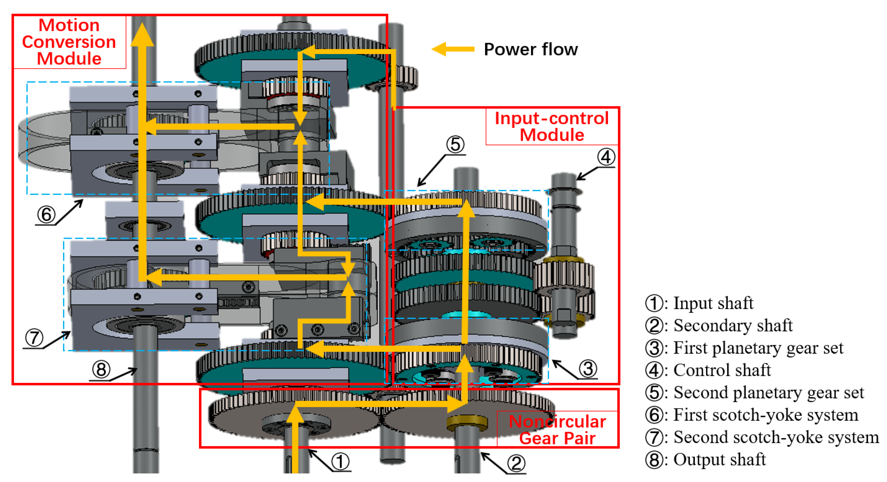
3.3.2. Infinitely Variable Transmissions

An infinitely variable transmission (IVT) was designed with cam systems to achieve continuously variable speed ratios via one-way bearings [94]. An active control system of the IVT was developed there with a closed-loop control that can adjust the eccentric motions of cams to control its speed ratios. However, the instantaneous speed ratios of this IVT had a periodic speed variation of up to 29% due to cam eccentricity. An upgraded IVT was designed with crank-slider systems that could continuously adjust the speed ratio in a wide range from zero to a certain value [95,96]. A noncircular gear pair was designed there to minimize the variation in instantaneous speed ratios that were introduced by crank-slider systems.
A new IVT was developed with a noncircular gear pair and two scotch-yoke systems (SYSs) to provide continuously variable speed ratios for given constant output speeds under any variable input speeds [97,98]. A schematic of the IVT is shown in Figure 7. An input power of the IVT was transmitted through the noncircular gear pair to an input-control module (ICM) with a modulated rotation speed [98]. Two planetary gear sets (PGSs) in the ICM combined the modulated rotation speed from the noncircular gear pair and the control speed of control gears. The combined rotation speeds of PGSs were transmitted to two SYSs in a motion-conversion module (MCM) via translational motions of yokes in SYSs. SYSs converted the translational speeds of yokes into rotation speeds of the output shaft via rack–pinion sets. The IVT can be scaled up by increasing the number of SYSs and the size of PGSs. Since the IVT can convert the power via gear contact forces without sliding power loss under high-torque and low-speed conditions, the IVT fits for tidal current energy harvesting. Additionally, the range of the variable speed ratio of the IVT is larger than that of a CVT and can start from zero. Since the output-to-input speed ratio of the IVT can be zero, a TCEC with the IVT can be disconnected from the grid without power electronic control and couplings at low tidal speeds in Region 1 in Figure 2. A large variable speed ratio range of the IVT enables high operation performance of the TCEC in its optimal speed range with the maximum harvesting efficiency. An integral time-delay feedback control with an open-loop control [99] and a closed-loop control [100,101] was designed to improve the control performance of the IVT for tidal current energy applications. Experimental investigation of the closed-loop control strategy of the IVT was conducted with variable tidal speed data [102,103]. Experimental results showed that the time-delay feedback control could reduce speed fluctuations of the output speed of the IVT.

3.4. Direct-Drive Systems

In a direct-drive system, a direct-drive generator is directly driven by the turbine hub [104,105,106]. Currently, direct-drive permanent-magnet (DDPM) synchronous generators are one of the attractive options for direct-drive systems for wind and marine energy harvesting since they have high power generation efficiency even though they are more expensive than generator systems with gearboxes [17,107,108,109]. DDPM synchronous generators were developed to improve the reliability of TCECs and reduce their O&M costs as gearboxes can be eliminated. Typically, DDPM synchronous generators can be divided into two categories: axial-flux and radial-flux DDPM synchronous generators, according to their flux directions in air gaps [110,111], as shown in Figure 8. The flux path in an axial-flux DDPM synchronous generator is predominantly axial; the flux enters and leaves the generator at the same side [112]. The flux in a radial-flux DDPM synchronous generator travels in the radial direction through its air gaps. Figure 8a shows a single-stator single-rotor axial-flux DDPM synchronous generator, which consists of a stator and a rotor. The stator can be manufactured with or without slots depending on the type of application [113]. Active conductors of the axial-flux DDPM synchronous generator are oriented along its radius direction and the magnet flux is oriented in its axial direction. Figure 8b shows a radial-flux DDPM synchronous generator in a rim-driven turbine. In this rim-driven structure, active conductors of the radial-flux DDPM synchronous generator are oriented along its axial direction and the magnetic flux is along its radial direction.
These axial-flux and radial-flux DDPM synchronous generators are associated with turbines of TCECs in pod-type and rim-driven structures, respectively, as shown in Figure 9 [114,115]. A hollow center turbine structure can be used for high-diameter radial-flux DDPM synchronous generators, as shown in Figure 9b. Generally, radial-flux DDPM synchronous generators have been the dominant force between these two DDPM synchronous generators, mainly due to the fact that these radial-flux DDPM synchronous generators have naturally evolved from induction generators [116]. However, there are many unique advantages to be gained with the use of axial-flux DDPM synchronous generators over radial-flux DDPM synchronous generators. The pod-type structure is mostly used for PMGs, which leads to compact-sized axial-flux DDPM synchronous generators with a higher power density compared to conventional radial-flux DDPM synchronous generators [117]. For tidal current energy harvesting, some direct-drive systems have been developed in both academic and industrial projects [104,118,119,120,121,122]. These studies particularly dealt with specific structure topologies of PMGs for TCECs. However, it has not been proven that the reliability of direct-drive TCECs is better than that of TCECs with gearboxes [21].
Figure 8. Schematic of DDPM synchronous generators: (a) a single-stator single-rotor axial-flux DDPM synchronous generator [113] and (b) a radial-flux DDPM synchronous generator [117].
Energies 15 09236 g008

4. Oil Condition Monitoring and Maintenance of Gearboxes

Generally, gearboxes are designed for a minimum lifespan of 20 years [123]. Since gearboxes comprise many elements, such as rotating shafts, gears, and bearings, the reliability of gearboxes is the product of the reliability of all failure modes for which there exist reliability calculations. However, many failure modes experienced in the operation of gearboxes do not have standardized reliability calculations. Hence, CMSs of gearboxes provide common solutions for early gearbox failure detection, which have been the focus of several studies [31,63,124,125,126,127,128,129]. Gearboxes of TCECs will experience high torque, thrust, and impact conditions [123,130]. OCM has been used for gearbox fault detection and the determination of a gearbox maintenance plan in the wind and marine energy industry [31,37,72].

4.1. Oils and Additives of Gearboxes of TCECs

The main functions of gearbox oils are: (i) reducing wear and friction; (ii) ensuring gearbox cooling and improving heat dissipation; and (iii) absorbing wear particles and protecting gears and bearings. In order to satisfy the requirements of these functions, gearbox oils need to preserve their properties during their lifespan, which are: (i) good aging and oxidation resistance; (ii) low foaming; (iii) good air separation capacity; (iv) high loading capacity; (v) good thermal stability; (vi) high viscosity indices; and (vii) good detergency [131]. Synthetic oils of gearboxes are gaining more acceptance in the wind and marine energy industry. While synthetic oils are more expensive than mineral oils, the high thermal stability and viscosity indices make synthetic oils attractive for manufacturers and operators of TCECs [132].
Generally, gearbox oils are composed of an oil base stock and some additives. There are two common oil base stocks for gearboxes of TCECs, i.e., poly-alpha-olefin (PAO) and poly-alkylene-glycol (PAG). Both PAO and PAG are synthetic oils. PAG has a higher viscosity index than PAO. PAO has a viscosity index between 140 and 180, while PAG has a viscosity index between 180 and 260 [133]. These high viscosity indices of PAO and PAG indicate better thermal and viscosity stability than those of mineral oils, which only have a viscosity index of around 90. Table 1 lists some other lubrication properties of oil base stocks of gearbox oils [29].
The additive content and formulation play a decisive role in the lubrication performance of gearbox oils. There are some types of additives of gearbox oils, including anti-wear (AW), extreme-pressure (EP), antioxidant, anti-foam, and anti-corrosion additives [134]. Some formulations of gearbox oils can include detergents. Table 2 lists functions and compounds of some types of additives of gearbox oils. However, some combinations of additives can reduce the lubrication performance of gearbox oils. Anti-corrosion additives can affect the lubrication performance of AW and EP additives. Detergents of gearbox oils can affect oil film generation between gear contact surfaces. Hence, understanding additive formulations with different additives and their properties is essential for the reliable lubrication performance of gearbox oils.

4.2. Oil Condition Monitoring

Due to oil degradation, gearbox oil properties will have negative changes, which can cause lubrication failure [134]. Degradation of gearbox oils can be affected by multiple aspects, i.e., oil temperature, loading, external contaminants, types of oils, and additives. In order to ensure that gearbox oils keep lubrication properties in optimal conditions, OCM is carried out, providing information on lubrication properties of gearbox oils and operation conditions of the gearbox, e.g., gear wear. The lubrication properties of gearbox oils are determined by checking their contamination and degradation [142]. Contamination of gearbox oils can be evaluated based on the content of metallic particles, carbonaceous materials, and other insoluble particles, i.e., everything in gearbox oils that does not belong to them. Degradation of gearbox oils can be evaluated by measuring their viscosities, detergencies, acidities, and dielectric constants [143,144,145].
Oil sampling and offline oil analysis are the most common OCM method for the identification of oil conditions [146]. This OCM method enables the determination of oil condition parameters shown in Table 3. On-site oil analysis devices and online oil sensors have been used to determine gearbox oil conditions [147]. Gearbox conditions are mostly monitored by using inductive wear sensors, which can identify contents of metallic and other insoluble particles in gearbox oils [148,149]. In addition, the cleanliness of gearbox oils can be identified using optical particle counters [31]. Since the conductivities of contaminants, broken oil molecules, or acids are different for different oils, these substances cause changes in the conductivities of gearbox oils. Inductive wear sensors and optical particle counters [150] monitor oil degradation conditions based on the relationship between dielectric constants and conductivities of gearbox oils [151,152].
However, the accuracy of these sensors highly depends on data interpretation and robustness of these sensors. Since conductivities and dielectric constants of gearbox oils depend on oil temperature, an oil temperature compensation algorithm was developed to separate changes in additive depletion and oil degradation due to changes in dielectric constants and conductivities, respectively [150].

4.3. Oil Debris Analysis

Since wear debris in gearbox oils can provide useful information about health conditions and wear behaviors of meshing gear tooth surfaces, friction couplings, bearings, and other rolling components, oil debris analysis technologies are effectively used for fault detection of gearboxes [30]. Oil debris analysis is also important to achieve the maximum service life, especially for gearboxes [153]. The amount, sizes, shapes, and composition of particles in gearbox oils can be monitored to determine gearbox faults without disassembling entire systems [154]. Currently, the most common oil debris analysis method is offline oil debris analysis [155]. For offline oil debris analysis, monitoring relevant diagnostic parameters of gearbox oils of commercial TCECs can be conducted via laboratory techniques using special reagents, instruments, and equipment, such as viscometers and optical emission spectrometers [156]. Generally, the recommended interval for oil debris analysis is once every six months [31]. Results of oil debris analysis can provide information about the wear status of tested gearboxes and guide owners/operators of TCECs’ O&M activities [31].
Currently, R&D of oil debris analysis focuses on developing its online real-time systems by using the Internet of things (IoT) to eliminate current restrictions of oil debris analysis technologies and potentially further increase the efficiency and reliability of OCM systems for TCECs [157]. Some particle counting sensors and oil condition sensors are generally installed in the gearbox lubrication loop [31,144,145,158]. However, these additional sensors of online real-time oil debris analysis systems increase the costs of O&M of TCECs. Furthermore, these online real-time oil debris analysis systems can have limitations in the detection of certain gearbox failures [31]. Data analysis of online real-time oil debris analysis systems can also be challenging due to its dependency on some operation conditions of gearboxes, e.g., temperature. In addition, oil debris analysis requirements are specific to particular gearbox manufacturers and gearbox oil suppliers, which generally differ among them; this limits applications of online real-time oil debris analysis systems for commercial purposes [157].
Since gear pitting and bearing spalling are the main sources of metallic wear debris particles in gearbox oils [159], the remaining useful life (RUL) of a gearbox is short when operators can obtain valid information from oil debris analysis. In order to offer adequate time for operators to plan maintenance inspections and repairs, a combination of oil debris analysis and a data-driven condition monitoring method is used to efficiently predict the RUL of drivetrains [160]. Some data-driven methods, e.g., neural network [161], fuzzy logic [162], and Bayesian network [163,164] methods, have been used for the maintenance management of gearboxes under variable load and speed fluctuation conditions. Current data-driven condition monitoring methods for oil debris analysis are based on some gearbox operation data, e.g., pump oil pressure and oil temperature [165].

4.4. Other Condition-Monitoring Methods

There are some other condition-monitoring methods that can provide sensitive detection of potential failure events of drivetrains of TCECs, i.e, vibration-based [166,167], SCADA-based [168,169], and acoustic emission [170,171] condition monitoring. These condition-monitoring methods can identify changes of different predetermined condition indicators of operation conditions of drivetrains. These predetermined condition indicators can quantify damage severity to estimate the RUL of drivetrains based on failure prediction models [18,172].
1. Vibration-based condition monitoring. Due to reliable responses to structure damage and ease of instrumentation, vibration-based condition monitoring is a prevalently used method for drivetrain components of TCECs with time-varying frequencies of vibration sources, e.g., gears and bearings [173,174]. Since variable tidal speeds dictate the rotation speeds of a rotor with speed fluctuations, the primary step of vibration-based condition monitoring of drivetrains is the angular sampling of variable rotation speeds of the rotor. An accurate and reliable measurement method to obtain variable rotation speeds of the rotor is using an angle encoder or a tachometer installed on the rotation shafts of drivetrains. The step that follows the angular sampling of variable rotation speeds of the rotor is signal processing using signal separation technologies to separate vibration signals of different drivetrain components obtained from accelerometers. General signal separation methods are empirical mode decomposition [175,176], discrete/random separation [177,178], and linear prediction filtering [179]. The last step is the identification of potential faults of drivetrains, which often focuses on tracking time-domain statistical indicators [38,180].
2. SCADA-based condition monitoring. A SCADA system for a TCEC is used for its condition monitoring based on hundreds of channels of data, i.e., environmental data, electrical conditions, control variables, and operation temperatures of different components of the TCEC [63,181,182]. Since only a small portion of these extensive data can provide valid condition information of the TCEC, it is challenging to extract this condition information. Some machine learning algorithms are used to analyze SCADA data. These machine learning algorithms of SCADA data can be divided into two categories [182,183]: supervised learning, i.e., classification and regression, and unsupervised learning, i.e., clustering. Angular velocity data of the drivetrain from the SCADA system can be used for fault detection and RUL estimation [18,172].
3. Acoustic emission condition monitoring. Since sound attenuation in underwater environments is a few dB/km at the frequency between 1 kHz and 1 MHz, acoustic emission condition monitoring can be a suitable solution to detect nonstationary signals of rotating components of the TCEC and can be performed on the TCEC or remotely [170,184]. Acoustic emission condition monitoring has been successfully deployed to identify different types of faults of drivetrains of TCECs [63,185]. However, there are still several challenges for acoustic emission condition monitoring of TCECs to be addressed in practice, i.e., filtering ambient noise, such as weather-related noise and shipping noise, and identifying overlapping acoustic emission signals of individual drivetrain components, such as bearings, gears, and couplings.

5. Discussion and Future Work

Modern marine renewable energy devices, e.g., TCECs, are high-value assets and there is an increasing interest in longer design life and lifetime extension. The choices of the drivetrain option and its O&M strategy are critical issues for the R&D of TCECs. Regarding the choice of the drivetrain option, geared drivetrains have high technology maturity. Gearboxes are becoming more reliable, which appears to be appropriate for TCECs. Direct-drive systems are an attractive choice for TCECs. However, they are more expensive compared to geared drivetrains and their manufacturing standardization is insufficient. In terms of the efficiency, planetary gearboxes have high efficiency. Using a direct-drive system would increase the efficiency of the drivetrain and may therefore cover the extra cost of its PMG, which still needs industry confirmation in the future [21,123]. Other types of gearboxes induce extra power loss that can sum up to quite large economical loss throughout the life of TCECs.
Since tidal energy is not stable, i.e., tidal speeds are variable at different times, there are great challenges in the operation of a generator bus-bar assembly of TCECs and in its grid connection [114]. Currently, there are few studies on maximum power control technologies of TCECs [115]. Since the harvestable tidal power is proportional to the cubic of the tidal speed, as shown in Equation (3), it is difficult to implement these controllers of TCECs. A variable-speed mechanical transmission is needed to achieve energy compensation. A lighter and more compact drivetrain design concept for TCECs will be the most cost-effective option in the future. This can effectively raise the energy harvesting efficiency and improve the stability of tidal energy.
Current OCM systems of gearboxes of TCECs are implemented by signal processing-based approaches [144]. In many cases, O&M procedures of gearboxes are performed with incomplete information, leading to erroneous diagnoses. OCM results of gearboxes are highly sensitive to external conditions and contamination. Oil condition monitoring results of gearboxes are altered when oil sampling positions are different, e.g., before or after filters. There are differences in oil condition monitoring results due to the cleaning effects of filters even if these samples are taken from the same gearbox at the same time [145]. Additionally, changes in gearbox oils, which imply different chemical compositions, additives, and proportions of additives, can contaminate oil condition monitoring results. In addition, oil condition monitoring results are also influenced by other situations, such as oil temperature, leakage, oil filling, and installation positions of portable offline filters [144]. The main drivers for the usage of offline oil debris analysis systems are to monitor diagnostic parameters that cannot be monitored by other online real-time oil debris analysis systems and also to identify failures of gearboxes and detect their early faults. Generally, oil debris analysis can be performed with vibration-based condition monitoring for effective detection of extensive gearbox faults to improve diagnosis reliability. While oil debris analysis is effective in oil condition monitoring of gearboxes, the accuracy of oil debris analysis is highly dependent on the types, numbers, and locations of sensors used. It is still challenging to develop a standardized and cost-effective oil debris analysis technique for gearboxes [31,157].
Oil analytics, including oil condition monitoring and oil debris analysis, are managed as one tool to determine the operating conditions of gearboxes. In order to improve the reliability, accuracy, and scope of oil analytics for gearboxes, it is necessary to integrate data-driven condition monitoring methods into oil analytics processes [165]. By using historical and real-time oil monitoring data, data-driven condition monitoring methods can be performed to achieve more reliable predictive monitoring and maintenance of gearboxes of TCECs [160]. The implementation of data-driven condition monitoring methods of oil analytics for gearboxes can be challenging in practical demonstrations and projects. While data-driven condition monitoring methods are able to predict future health conditions of gearboxes, the reliability of short-term prediction is higher than that of long-term one. When dealing with long-term prediction of health conditions of gearboxes, data-driven condition monitoring methods may not be accurate enough. To provide a reliable maintenance decision of gearboxes, data-driven condition monitoring methods need to be further investigated.
In addition to the improved diagnostic reliability of oil analytics for gearboxes, the realization of more accurate maintenance planning is needed to enable more profound impacts on O&M costs of TCECs. The lack of similarity in developing standardized OCM systems of gearboxes for different gearbox oils can lead to mispredictions of OCM systems. Furthermore, oil samples should be sent to laboratories after they are collected within a certain period of time stipulated by laboratories and maintainers. However, communication among TCEC locations and laboratories still has deficiencies, especially in deep-sea environments. Hence, future work on OCM systems of gearboxes of TCECs would attempt to fill these gaps by incorporating more investigations on wireless communication technologies of underwater IoT.

6. Conclusions

This paper presents the general state-of-the-art drivetrain technologies for TCECs and reviews upcoming advances in oil condition monitoring and maintenance methods of gearboxes. Regarding the integration of electro-mechanical systems, geared drivetrains seem to be the dominant technology. However, competition between geared drivetrains and direct-drive systems is still ongoing for the development of TCECs. A lighter and more compact variable-speed drivetrain design concept for TCECs will be appropriate for TCECs. Further optimization of designs of drivetrains for the integration of electro-mechanical systems in TCECs should also be considered.
Given the criticality of gearboxes of drivetrains of TCECs, the gearbox oil maintenance is seen as a necessary O&M work. Quantitative analysis confirms the sensitivity of OCM results of gearboxes to different O&M aspects, which can identify potential failure risks of gearboxes. These quantitative analysis results and conclusions will help maintainers and laboratories to make timely decisions on different O&M aspects of gearboxes. Oil degradation of gearbox oils of TCECs can be evaluated based on reliable OCM results of the evolution of different elements, e.g., additives, wear particles, viscosities, and water contents. Failure risks of gearboxes can be predicted based on oil debris analysis results. Hence, operators and maintainers can take actions to stop the propagation of early problems. OCM systems should rapidly detect and diagnose incipient problems and predict gearbox failures without human intervention, particularly given the difficulty of manual sampling in deep-sea environments. Online real-time oil debris analysis of this process is highly desirable yet remains a challenge for existing underwater IoT technologies. A combined OCM method with some vibration-based, SCADA-based, and acoustic emission condition monitoring has the potential to improve the reliability and accuracy of OCM for gearboxes of TCECs. However, considerable further research on these combined condition monitoring methods is required to achieve this goal.

Author Contributions

Conceptualization, G.L. and W.Z.; methodology, G.L. and W.Z.; software, G.L.; validation, G.L. and W.Z.; formal analysis, G.L.; investigation, G.L.; resources, G.L. and W.Z.; data curation, G.L.; writing—original draft preparation, G.L.; writing—review and editing, W.Z.; visualization, G.L.; supervision, W.Z.; project administration, W.Z.; funding acquisition, W.Z. All authors have read and agreed to the published version of the manuscript.

Funding

This research was funded by the Maryland Energy Innovation Institute’s Energy Innovation Seed Grant, the Maryland Technology Development Corporation’s Maryland Innovation Initiative Grant, and the National Science Foundation under grant number CMMI-1763024.

Institutional Review Board Statement

Not applicable.

Informed Consent Statement

Not applicable.

Data Availability Statement

Not applicable.

Acknowledgments

The authors are grateful for the financial support from the Maryland Energy Innovation Institute’s Energy Innovation Seed Grant, the Maryland Technology Development Corporation’s Maryland Innovation Initiative Grant, and the National Science Foundation under Award No. CMMI-1763024.

Conflicts of Interest

The authors declare no conflict of interest.

Abbreviations

The following abbreviations are used in this manuscript:
ACAlternating current
AWAnti-wear
CMSCondition monitoring system
CVTContinuously variable transmission
DCDirect current
DDPMDirect-drive permanent magnet
EPExtreme-pressure
ICMInput-control module
IoTInternet of things
IVTInfinitely variable transmission
MCMMotion-conversion module
MCTMarine Current Turbine
MPPTMaximum power point tracking
O&MOperation and maintenance
OCMOil condition monitoring
PMGPermanent-magnet generator
R&DResearch and development
RULRemaining useful life
SCADASupervisory control and data acquisition
SPGSuperposition ear
SYSScotch-yoke system
TCECTidal current energy converter
TGLTidal Generation Ltd

References

  1. Pelc, R.; Fujita, R.M. Renewable energy from the ocean. Mar. Policy 2002, 26, 471–479. [Google Scholar] [CrossRef]
  2. Wilberforce, T.; El Hassan, Z.; Durrant, A.; Thompson, J.; Soudan, B.; Olabi, A.G. Overview of ocean power technology. Energy 2019, 175, 165–181. [Google Scholar] [CrossRef] [Green Version]
  3. O’Rourke, F.; Boyle, F.; Reynolds, A. Tidal energy update 2009. Appl. Energy 2010, 87, 398–409. [Google Scholar] [CrossRef]
  4. Liu, H.-W.; Ma, S.; Li, W.; Gu, H.-G.; Lin, Y.-G.; Sun, X.-J. A review on the development of tidal current energy in China. Renew. Sustain. Energy Rev. 2011, 15, 1141–1146. [Google Scholar] [CrossRef]
  5. IRENA. Fostering a Blue Economy: Offshore Renewable Energy; IRENA: Abu Dhabi, United Arab Emirates, 2020. [Google Scholar]
  6. IRENA. Innovation Outlook: Ocean Energy Technologies; IRENA: Abu Dhabi, United Arab Emirates, 2020. [Google Scholar]
  7. Neill, S.P.; Litt, E.J.; Couch, S.J.; Davies, A.G. The impact of tidal stream turbines on large-scale sediment dynamics. Renew. Energy 2009, 34, 2803–2812. [Google Scholar] [CrossRef]
  8. Boehlert, G.W.; Gill, A.B. Environmental and ecological effects of ocean renewable energy development: A current synthesis. Oceanography 2010, 23, 68–81. [Google Scholar] [CrossRef] [Green Version]
  9. Copping, A.; Smith, C.; Hanna, L.; Battey, H.; Whiting, J.; Reed, M.; Brown-Saracino, J.; Gilman, P.; Massaua, M. Tethys: Developing a commons for understanding environmental effects of ocean renewable energy. Int. J. Mar. Energy 2013, 3, 41–51. [Google Scholar] [CrossRef]
  10. Kempener, R.; Neumann, F. Tidal Energy Technology Brief; International Renewable Energy Agency (IRENA): Abu Dhabi, United Arab Emirates, 2014; pp. 1–34. [Google Scholar]
  11. Kanellos, F.; Papathanassiou, S.; Hatziargyriou, N. Dynamic analysis of a variable speed wind turbine equipped with a voltage source AC/DC/AC converter interface and a reactive current control loop. In Proceedings of the 2000 10th Mediterranean Electrotechnical Conference. Information Technology and Electrotechnology for the Mediterranean Countries. Proceedings. MeleCon 2000 (Cat. No. 00CH37099), Limassol, Cyprus, 29–31 May 2000; Volume 3, pp. 986–989. [Google Scholar]
  12. Singh, M.; Khadkikar, V.; Chandra, A. Grid synchronisation with harmonics and reactive power compensation capability of a permanent magnet synchronous generator-based variable speed wind energy conversion system. IET Power Electron. 2011, 4, 122–130. [Google Scholar] [CrossRef] [Green Version]
  13. Deraz, S.; Kader, F.A. A new control strategy for a stand-alone self-excited induction generator driven by a variable speed wind turbine. Renew. Energy 2013, 51, 263–273. [Google Scholar] [CrossRef]
  14. Benelghali, S.; Benbouzid, M.E.H.; Charpentier, J.F. Generator systems for marine current turbine applications: A comparative study. IEEE J. Ocean. Eng. 2012, 37, 554–563. [Google Scholar] [CrossRef]
  15. Chen, L.; Lam, W.H. A review of survivability and remedial actions of tidal current turbines. Renew. Sustain. Energy Rev. 2015, 43, 891–900. [Google Scholar] [CrossRef] [Green Version]
  16. Djebarri, S.; Charpentier, J.F.; Scuiller, F.; Benbouzid, M. A systemic design methodology of PM generators for fixed-pitch marine current turbines. In Proceedings of the 2014 First International Conference on Green Energy ICGE 2014, Sfax, Tunisia, 25 March 2014; pp. 32–37. [Google Scholar]
  17. Polinder, H.; Van der Pijl, F.F.; De Vilder, G.J.; Tavner, P.J. Comparison of direct-drive and geared generator concepts for wind turbines. IEEE Trans. Energy Convers. 2006, 21, 725–733. [Google Scholar] [CrossRef] [Green Version]
  18. Moghadam, F.K.; Nejad, A.R. Online condition monitoring of floating wind turbines drivetrain by means of digital twin. Mech. Syst. Signal Process. 2022, 162, 108087. [Google Scholar] [CrossRef]
  19. Harzendorf, F. Geared vs. direct drive–a holistic system comparison. In Proceedings of the Conference for Wind Power Drives, Virtual Event, 9–11 March 2021. [Google Scholar]
  20. Harzendorf, F.; Schelenz, R.; Jacobs, G. Reducing cost uncertainty in the drivetrain design decision with a focus on the operational phase. Wind Energy Sci. 2021, 6, 571–584. [Google Scholar] [CrossRef]
  21. Touimi, K.; Benbouzid, M.; Tavner, P. Tidal stream turbines: With or without a Gearbox? Ocean Eng. 2018, 170, 74–88. [Google Scholar] [CrossRef]
  22. Polinder, H.; Ferreira, J.A.; Jensen, B.B.; Abrahamsen, A.B.; Atallah, K.; McMahon, R.A. Trends in wind turbine generator systems. IEEE J. Emerg. Sel. Top. Power Electron. 2013, 1, 174–185. [Google Scholar] [CrossRef]
  23. Melikoglu, M. Current status and future of ocean energy sources: A global review. Ocean Eng. 2018, 148, 563–573. [Google Scholar] [CrossRef]
  24. Benbouzid, M.; Astolfi, J.A.; Bacha, S.; Charpentier, J.F.; Machmoum, M.; Maître, T.; Roye, D. Concepts, modeling and control of tidal turbines. In Marine Renewable Energy Handbook; Wiley: Hoboken, NJ, USA, 2012. [Google Scholar]
  25. Moon, S.H.; Park, B.G.; Kim, J.W.; Kim, J.M. Maximum power-point tracking control using perturb and observe algorithm for tidal current generation system. Int. J. Precis. Eng. Manuf.-Green Technol. 2020, 7, 849–858. [Google Scholar] [CrossRef]
  26. Kang, D.; Kim, J.; Him, J.; Shin, A.; Oh, M.; Kim, J. The design for automatic operation of Tidal power generation equipment. In Proceedings of the KIEE Conference; The Korean Institute of Electrical Engineers: Seoul, Republic of Korea, 2005; pp. 2579–2581. [Google Scholar]
  27. Wilkinson, M.; Darnell, B.; Van Delft, T.; Harman, K. Comparison of methods for wind turbine condition monitoring with SCADA data. IET Renew. Power Gener. 2014, 8, 390–397. [Google Scholar] [CrossRef]
  28. Bangalore, P.; Patriksson, M. Analysis of SCADA data for early fault detection, with application to the maintenance management of wind turbines. Renew. Energy 2018, 115, 521–532. [Google Scholar] [CrossRef]
  29. Coronado, D.; Wenske, J. Monitoring the oil of wind-turbine gearboxes: Main degradation indicators and detection methods. Machines 2018, 6, 25. [Google Scholar] [CrossRef] [Green Version]
  30. Benbouzid, M.; Berghout, T.; Sarma, N.; Djurović, S.; Wu, Y.; Ma, X. Intelligent Condition Monitoring of Wind Power Systems: State of the Art Review. Energies 2021, 14, 5967. [Google Scholar] [CrossRef]
  31. Sheng, S. Monitoring of wind turbine gearbox condition through oil and wear debris analysis: A full-scale testing perspective. Tribol. Trans. 2016, 59, 149–162. [Google Scholar] [CrossRef]
  32. Mauntz, M.R.; Peuser, J. Condition based maintenance of wind turbines by 24/7 monitoring of oil quality and additive consumption: Identification of critical operation conditions and determination of the next oil change. In Conference for Wind Power Drives 2017: Tagungsband zur Konferenz. BoD—Books on Demand; FLOGEN Star Outreach: Montreal, QC, Canada, 2017; Volume 3, p. 391. [Google Scholar]
  33. Hamilton, A.; Quail, F. Detailed state of the art review for the different online/inline oil analysis techniques in context of wind turbine gearboxes. ASME J. Tribol. 2011, 133, 044001. [Google Scholar] [CrossRef] [Green Version]
  34. Elasha, F.; Mba, D.; Togneri, M.; Masters, I.; Teixeira, J.A. A hybrid prognostic methodology for tidal turbine gearboxes. Renew. Energy 2017, 114, 1051–1061. [Google Scholar] [CrossRef]
  35. Faris Elasha, D.M.; Teixeira, J.A. Condition monitoring philosophy for tidal turbines. Int. J. Perform. Eng. 2014, 10, 521. [Google Scholar]
  36. Yang, W.; Tavner, P.J.; Crabtree, C.J.; Feng, Y.; Qiu, Y. Wind turbine condition monitoring: Technical and commercial challenges. Wind Energy 2014, 17, 673–693. [Google Scholar] [CrossRef] [Green Version]
  37. Márquez, F.P.G.; Tobias, A.M.; Pérez, J.M.P.; Papaelias, M. Condition monitoring of wind turbines: Techniques and methods. Renew. Energy 2012, 46, 169–178. [Google Scholar] [CrossRef]
  38. Tchakoua, P.; Wamkeue, R.; Ouhrouche, M.; Slaoui-Hasnaoui, F.; Tameghe, T.A.; Ekemb, G. Wind turbine condition monitoring: State-of-the-art review, new trends, and future challenges. Energies 2014, 7, 2595–2630. [Google Scholar] [CrossRef] [Green Version]
  39. Güney, M.S.; Kaygusuz, K. Hydrokinetic energy conversion systems: A technology status review. Renew. Sustain. Energy Rev. 2010, 14, 2996–3004. [Google Scholar] [CrossRef]
  40. Laws, N.D.; Epps, B.P. Hydrokinetic energy conversion: Technology, research, and outlook. Renew. Sustain. Energy Rev. 2016, 57, 1245–1259. [Google Scholar] [CrossRef]
  41. Neill, S.P.; Angeloudis, A.; Robins, P.E.; Walkington, I.; Ward, S.L.; Masters, I.; Lewis, M.J.; Piano, M.; Avdis, A.; Piggott, M.D.; et al. Tidal range energy resource and optimization–Past perspectives and future challenges. Renew. Energy 2018, 127, 763–778. [Google Scholar] [CrossRef]
  42. Segura, E.; Morales, R.; Somolinos, J.; López, A. Techno-economic challenges of tidal energy conversion systems: Current status and trends. Renew. Sustain. Energy Rev. 2017, 77, 536–550. [Google Scholar] [CrossRef]
  43. Lewis, M.; Neill, S.; Robins, P.; Hashemi, M. Resource assessment for future generations of tidal-stream energy arrays. Energy 2015, 83, 403–415. [Google Scholar] [CrossRef] [Green Version]
  44. Lisboa, A.; Vieira, T.; Guedes, L.; Vieira, D.; Saldanha, R. Optimal analytic dispatch for tidal energy generation. Renew. Energy 2017, 108, 371–379. [Google Scholar] [CrossRef]
  45. Uihlein, A.; Magagna, D. Wave and tidal current energy—A review of the current state of research beyond technology. Renew. Sustain. Energy Rev. 2016, 58, 1070–1081. [Google Scholar] [CrossRef]
  46. Johnstone, C.; Pratt, D.; Clarke, J.; Grant, A. A techno-economic analysis of tidal energy technology. Renew. Energy 2013, 49, 101–106. [Google Scholar] [CrossRef]
  47. Neary, V.S.; Previsic, M.; Jepsen, R.; Lawson, M.; Yu, Y.H.; Copping, A.; Arnold, F.; Hallett, K.C.; Murray, D. Methodology for Design and Economic Analysis of Marine Energy Conversion (MEC) Technologies; Technical Report; Sandia National Laboratories: Albuquerque, NM, USA, 2014.
  48. Jenkins, N.; Burton, T.L.; Bossanyi, E.; Sharpe, D.; Graham, M. Wind Energy Handbook; John Wiley & Sons: Hoboken, NJ, USA, 2021. [Google Scholar]
  49. Garrett, C.; Cummins, P. The efficiency of a turbine in a tidal channel. J. Fluid Mech. 2007, 588, 243–251. [Google Scholar] [CrossRef] [Green Version]
  50. Hau, E. Wind Turbines: Fundamentals, Technologies, Application, Economics; Springer Science & Business Media: Berlin/Heidelberg, Germany, 2013. [Google Scholar]
  51. Jenne, D.S.; Yu, Y.H.; Neary, V. Levelized Cost of Energy Analysis of Marine and Hydrokinetic Reference Models; Technical Report; National Renewable Energy Lab. (NREL): Golden, CO, USA, 2015.
  52. Domenech, J.; Eveleigh, T.; Tanju, B. Marine Hydrokinetic (MHK) systems: Using systems thinking in resource characterization and estimating costs for the practical harvest of electricity from tidal currents. Renew. Sustain. Energy Rev. 2018, 81, 723–730. [Google Scholar] [CrossRef]
  53. Beam, M.J.; Kline, B.L.; Elbing, B.E.; Straka, W.; Fontaine, A.A.; Lawson, M.; Li, Y.; Thresher, R.; Previsic, M. Marine hydrokinetic turbine power-take-off design for optimal performance and low impact on cost-of-energy. In Proceedings of the 32nd International Conference on Offshore Mechanics and Arctic Engineering (OMAE 2013), Nabtes, France, 9–14 June 2013; Volume 55423, p. V008T09A041. [Google Scholar]
  54. Nejad, A.R.; Torsvik, J. Drivetrains on floating offshore wind turbines: Lessons learned over the last 10 years. Forsch. Im Ingenieurwesen 2021, 85, 335–343. [Google Scholar] [CrossRef]
  55. Reisch, S. Elastic interaction of the gearbox in powertrain concepts with increased integration level. In Proceedings of the 5th Conference for Wind Power Drives (CWD), Virtual Event, 9–10 March 2021. [Google Scholar]
  56. Abundo, M.L.S.; Xiang, M.K.W.; Kiat, O.B.; Huat, W.T.H.; Hon, C.K. Combinatorial optimization for selection of gearboxes & generators for tidal in-stream energy systems. In Proceedings of the 2012 10th International Power & Energy Conference (IPEC), Ho Chi Minh City, Vietnam, 12–14 December 2012; pp. 544–549. [Google Scholar]
  57. Kuschke, M.; Pertzsch, S.; Strunz, K. Modeling of tidal energy conversion systems for primary response testing. In Proceedings of the 2012 IEEE Power and Energy Society General Meeting, San Diego, CA, USA, 22–26 July 2012; pp. 1–6. [Google Scholar]
  58. Abo-Khalil, A.G.; Alghamdi, A.S. MPPT of permanent magnet synchronous generator in tidal energy systems using support vector regression. Sustainability 2021, 13, 2223. [Google Scholar] [CrossRef]
  59. Ren, Z.; Wang, K.; Li, W.; Jin, L.; Dai, Y. Probabilistic power flow analysis of power systems incorporating tidal current generation. IEEE Trans. Sustain. Energy 2017, 8, 1195–1203. [Google Scholar] [CrossRef]
  60. Belkhier, Y.; Achour, A. Passivity-based voltage controller for tidal energy conversion system with permanent magnet synchronous generator. Int. J. Control Autom. Syst. 2021, 19, 988–998. [Google Scholar] [CrossRef]
  61. Jo, C.H.; Lee, K.H.; Lee, J.H.; Nichita, C. Multi-arrayed tidal current energy farm and the integration method of the power transportation. In Proceedings of the International Symposium on Power Electronics Power Electronics, Electrical Drives, Automation and Motion, Sorrento, Italy, 22–24 June 2012; pp. 1428–1431. [Google Scholar]
  62. Zhang, J.; Moreau, L.; Guo, J.; Machmoum, M. Joint optimization of electromagnetic structure and control of a double stator permanent magnet generator for tidal energy applications. In Proceedings of the 2014 International Power Electronics and Application Conference and Exposition, Shanghai, China, 5–8 November 2014; pp. 485–489. [Google Scholar]
  63. Nejad, A.R.; Keller, J.; Guo, Y.; Sheng, S.; Polinder, H.; Watson, S.; Dong, J.; Qin, Z.; Ebrahimi, A.; Schelenz, R.; et al. Wind turbine drivetrains: State-of-the-art technologies and future development trends. Wind Energy Sci. 2022, 7, 387–411. [Google Scholar] [CrossRef]
  64. Chen, H.; Ait-Ahmed, N.; Zaim, E.; Machmoum, M. Marine tidal current systems: State of the art. In Proceedings of the 2012 IEEE International Symposium on Industrial Electronics, Hangzhou, China, 28–31 May 2012; pp. 1431–1437. [Google Scholar]
  65. Plagge, A.M.; Jestings, L.; Epps, B.P. Next-generation hydrokinetic power take-off via a novel variable-stroke hydraulic system. In Proceedings of the International Conference on Offshore Mechanics and Arctic Engineering (OMAE 2014), San Francisco, CA, USA, 8–13 June 2014; Volume 45547, p. V09BT09A018. [Google Scholar]
  66. Bruce, A.J. Tidal Energy System for On-Shore Power Generation; DOE Marine and Hydrokinetic Technology Readiness Initiative; Technical Report; Sunlight Photonics Inc.: South Plainfield, NJ, USA, 2012. [Google Scholar]
  67. Mahato, A.C.; Ghoshal, S.K. Various power transmission strategies in wind turbine: An overview. Int. J. Dyn. Control 2019, 7, 1149–1156. [Google Scholar] [CrossRef]
  68. Payne, G.; Kiprakis, A.; Ehsan, M.; Rampen, W.H.S.; Chick, J.; Wallace, A. Efficiency and dynamic performance of Digital Displacement™ hydraulic transmission in tidal current energy converters. Proc. Inst. Mech. Eng. Part A J. Power Energy 2007, 221, 207–218. [Google Scholar] [CrossRef]
  69. Liu, H.-W.; Li, W.; Lin, Y.-G.; Ma, S. Tidal current turbine based on hydraulic transmission system. J. Zhejiang Univ.-SCIENCE A 2011, 12, 511–518. [Google Scholar] [CrossRef]
  70. Toumi, S.; Elbouchikhi, E.; Amirat, Y.; Benbouzid, M.; Feld, G. Magnet failure-resilient control of a direct-drive tidal turbine. Ocean Eng. 2019, 187, 106207. [Google Scholar] [CrossRef]
  71. Khare, V.; Khare, C.; Nema, S.; Baredar, P. Tidal Energy Systems: Design, Optimization and Control; Elsevier: Amsterdam, The Netherlands, 2018. [Google Scholar]
  72. Marques, P.M.; Camacho, R.; Martins, R.C.; Seabra, J.H. Efficiency of a planetary multiplier gearbox: Influence of operating conditions and gear oil formulation. Tribol. Int. 2015, 92, 272–280. [Google Scholar] [CrossRef]
  73. Elmaati, Y.A.; El Bahir, L.; Faitah, K. Residual generation for the gearbox efficiency drop fault detection in the NREL 1.5 WindPact turbine. In Proceedings of the 2015 International Conference on Electrical and Information Technologies (ICEIT), Marrakech, Morocco, 25–27 March 2015; pp. 77–81. [Google Scholar]
  74. Warren, T. FoDTEC (Forensic Decommissioning of Tidal Energy Converters) Final Summary Report; Technical Report; Interreg North-West Europe FORESEA: Lille, France, 2012. [Google Scholar]
  75. Snieckus, D. Pioneering SeaGen Tidal Power Turbine Decommissioned. 2019. Available online: https://www.rechargenews.com/technology/pioneering-seagen-tidal-power-turbine-decommissioned/2-1-644606 (accessed on 24 July 2021).
  76. Poindexter, G. 1.5-MW AR1500 Tidal Turbine Grid-Connected, Operational at Full Power in Scotland. 2017. Available online: https://www.renewableenergyworld.com/baseload/1-5-mw-ar1500-tidal-turbine-grid-connected-operational-at-full-power-in-scotland/#gref (accessed on 3 February 2017).
  77. Poindexter, G. Tidal Power Technology Company Atlantis Resources Posts US$9.4 Million Loss for 2016. 2017. Available online: https://www.hydroreview.com/business-finance/tidal-power-technology-company-atlantis-resources-posts-us-9-4-million-loss-for-2016/#gref (accessed on 1 June 2017).
  78. McPhee, D. Scotrenewables Rebrands as It Looks to Raise 7M Investment; Technical Report; Energy Voice: Aberdeen, UK, 2018. [Google Scholar]
  79. Whitlock, R. SR2000 Tidal Turbine Delivered Impressive Performance throughout the Winter. 2018. Available online: https://www.renewableenergymagazine.com/ocean_energy/sr2000-tidal-turbine-delivered-impressive-performance-through-20180116 (accessed on 16 January 2018).
  80. Dong, X.; Wang, Z.; Shen, P.; Song, Y.; Yu, J. Novel design of speed-increasing compound coupled hydromechanical transmission on tidal current turbine for power generation. E3S Web Conf. EDP Sci. 2020, 162, 03001. [Google Scholar] [CrossRef]
  81. He, X.; Xiao, G.; Hu, B.; Tan, L.; Tang, H.; He, S.; He, Z. The applications of energy regeneration and conversion technologies based on hydraulic transmission systems: A review. Energy Convers. Manag. 2020, 205, 112413. [Google Scholar] [CrossRef]
  82. Liu, H.; Lin, Y.; Shi, M.; Li, W.; Gu, H.; Xu, Q.; Tu, L. A novel hydraulic-mechanical hybrid transmission in tidal current turbines. Renew. Energy 2015, 81, 31–42. [Google Scholar] [CrossRef]
  83. Fan, Y.; Mu, A.; Ma, T. Modeling and control of a hybrid wind-tidal turbine with hydraulic accumulator. Energy 2016, 112, 188–199. [Google Scholar] [CrossRef]
  84. Laguna, A.J.; Diepeveen, N.F.; Van Wingerden, J.W. Analysis of dynamics of fluid power drive-trains for variable speed wind turbines: Parameter study. IET Renew. Power Gener. 2014, 8, 398–410. [Google Scholar] [CrossRef]
  85. Qian, P.; Feng, B.; Liu, H.; Tian, X.; Si, Y.; Zhang, D. Review on configuration and control methods of tidal current turbines. Renew. Sustain. Energy Rev. 2019, 108, 125–139. [Google Scholar] [CrossRef]
  86. Müller, H.; Pöller, M.; Basteck, A.; Tilscher, M.; Pfister, J. Grid compatibility of variable speed wind turbines with directly coupled synchronous generator and hydro-dynamically controlled gearbox. In Proceedings of the Sixth International Workshop on Large-Scale Integration of Wind Power and Transmission Networks for Offshore Wind Farms, Delft, The Netherlands, 26–28 October 2006; pp. 307–315. [Google Scholar]
  87. Giallanza, A.; Porretto, M.; Cannizzaro, L.; Marannano, G. Analysis of the maximization of wind turbine energy yield using a continuously variable transmission system. Renew. Energy 2017, 102, 481–486. [Google Scholar] [CrossRef]
  88. Verdonschot, M. Modeling and Control of Wind Turbines Using a Continuously Variable Transmission. Master’s Thesis, Eindhoven University of Technology, Eindhoven, The Netherlands, 2009. [Google Scholar]
  89. Yin, X.X.; Lin, Y.G.; Li, W.; Liu, H.W.; Gu, Y.J. Output power control for hydro-viscous transmission based continuously variable speed wind turbine. Renew. Energy 2014, 72, 395–405. [Google Scholar] [CrossRef]
  90. Shamshirband, S.; Petković, D.; Amini, A.; Anuar, N.B.; Nikolić, V.; Ćojbašić, Ž.; Kiah, M.L.M.; Gani, A. Support vector regression methodology for wind turbine reaction torque prediction with power-split hydrostatic continuous variable transmission. Energy 2014, 67, 623–630. [Google Scholar] [CrossRef]
  91. Van Berkel, K.; Hofman, T.; Vroemen, B.; Steinbuch, M. Optimal control of a mechanical hybrid powertrain. IEEE Trans. Veh. Technol. 2011, 61, 485–497. [Google Scholar] [CrossRef]
  92. Cotrell, J. Motion Technologies CRADA CRD-03-130: Assessing the Potential of a Mechanical Continuously Variable Transmission; Technical Report; National Renewable Energy Lab.: Golden, CO, USA, 2004.
  93. Alkan, D. Investigating CVT as a Transmission System Option for Wind Turbines. Master’s Thesis, KTH School of Industrial Engineering and Management, Stockholm, Sweden, 2013. [Google Scholar]
  94. Zhu, W.; Wang, X. Modeling and control of an infinitely variable speed converter. ASME J. Dyn. Syst. Meas. Control 2014, 136, 031015. [Google Scholar] [CrossRef]
  95. Wang, X.; Zhu, W. Design, modeling, and simulation of a geared infinitely variable transmission. ASME J. Mech. Des. 2014, 136. [Google Scholar] [CrossRef]
  96. Zhu, W.; Wang, X. Geared Infinitely Variable Transmission. U.S. Patent 9,222,558 B2, 12 December 2015. [Google Scholar]
  97. Wang, X.F.; Zhu, W.D. Design, modeling, and experimental validation of a novel infinitely variable transmission based on scotch yoke systems. ASME J. Mech. Des. 2016, 138, 015001. [Google Scholar] [CrossRef]
  98. Li, G.; Zhu, W. Design and power loss evaluation of a noncircular gear pair for an infinitely variable transmission. Mech. Mach. Theory 2021, 156, 104137. [Google Scholar] [CrossRef]
  99. Wang, X.F.; Zhu, W.D. Design and stability analysis of an integral time-delay feedback control combined with an open-loop control for an infinitely variable transmission system. ASME J. Dyn. Syst. Meas. Control 2018, 140, 011007. [Google Scholar] [CrossRef]
  100. Li, G.; Wang, X.; Zhu, W. Theoretical and experimental investigation on an integral time-delay feedback control combined with a closed-loop control for an infinitely variable transmission system. Mech. Mach. Theory 2021, 164, 104410. [Google Scholar] [CrossRef]
  101. Zhu, W.; Wang, X.; Li, G. Closed-Loop Control of an Infinitely Variable Transmission. U.S. Patent 11,268,615 B2, 8 March 2022. [Google Scholar]
  102. Li, G.; Zhu, W. Experimental investigation on control of an infinitely variable transmission system for tidal current energy converters. IEEE/ASME Trans. Mechatron. 2021, 26, 1960–1967. [Google Scholar] [CrossRef]
  103. Li, G.; Zhu, W. Time-delay closed-loop control of an infinitely variable transmission system for tidal current energy converters. Renew. Energy 2022, 189, 1120–1132. [Google Scholar] [CrossRef]
  104. Keysan, O.; McDonald, A.S.; Mueller, M. A direct drive permanent magnet generator design for a tidal current turbine (SeaGen). In Proceedings of the 2011 IEEE International Electric Machines & Drives Conference (IEMDC), Niagara Falls, ON, Canada, 5–8 May 2011; pp. 224–229. [Google Scholar]
  105. McMillan, D.; Ault, G.W. Techno-economic comparison of operational aspects for direct drive and gearbox-driven wind turbines. IEEE Trans. Energy Convers. 2010, 25, 191–198. [Google Scholar] [CrossRef] [Green Version]
  106. Ousmane Samb, S.; Bernard, N.; Fouad Benkhoris, M.; Kien Bui, H. Design optimization of a direct-drive electrically excited synchronous generator for tidal wave energy. Energies 2022, 15, 3174. [Google Scholar] [CrossRef]
  107. Delfino, F.; Denegri, G.; Invernizzi, M.; Pampararo, F.; Procopio, R.; Rossi, M. Modeling and control of DDPM wind generators. In Proceedings of the 45th International Universities Power Engineering Conference UPEC2010, Cardiff, UK, 31August–3 September 2010; pp. 1–5. [Google Scholar]
  108. Li, H.; Chen, Z. Overview of different wind generator systems and their comparisons. IET Renew. Power Gener. 2008, 2, 123–138. [Google Scholar] [CrossRef] [Green Version]
  109. Faiz, J.; Nematsaberi, A. Linear electrical generator topologies for direct-drive marine wave energy conversion-an overview. IET Renew. Power Gener. 2017, 11, 1163–1176. [Google Scholar] [CrossRef]
  110. Chen, Y.; Pillay, P.; Khan, A. PM wind generator topologies. IEEE Trans. Ind. Appl. 2005, 41, 1619–1626. [Google Scholar] [CrossRef] [Green Version]
  111. Singh, A.; Benzaquen, J.; Mirafzal, B. Current source generator–converter topology for direct-drive wind turbines. IEEE Trans. Ind. Appl. 2017, 54, 1663–1670. [Google Scholar] [CrossRef]
  112. Kahourzade, S.; Mahmoudi, A.; Ping, H.W.; Uddin, M.N. A comprehensive review of axial-flux permanent-magnet machines. Can. J. Electr. Comput. Eng. 2014, 37, 19–33. [Google Scholar] [CrossRef]
  113. Amin, S.; Khan, S.; Bukhari, S.S.H. A comprehensive review on axial flux machines and its applications. In Proceedings of the 2019 2nd International Conference on Computing, Mathematics and Engineering Technologies (iCoMET), Sukkur, Pakistan, 30–31 January 2019; pp. 1–7. [Google Scholar]
  114. Zhou, Z.; Benbouzid, M.; Charpentier, J.F.; Scuiller, F.; Tang, T. Developments in large marine current turbine technologies—A review. Renew. Sustain. Energy Rev. 2017, 71, 852–858. [Google Scholar] [CrossRef]
  115. Zhou, Z.; Scuiller, F.; Charpentier, J.F.; Benbouzid, M.; Tang, T. An up-to-date review of large marine tidal current turbine technologies. In Proceedings of the 2014 International Power Electronics and Application Conference and Exposition, Shanghai, China, 1–7 November 2014; pp. 480–484. [Google Scholar]
  116. Chen, Y.; Fu, W.N.; Ho, S.L.; Liu, H. A quantitative comparison analysis of radial-flux, transverse-flux, and axial-flux magnetic gears. IEEE Trans. Magn. 2014, 50, 1–4. [Google Scholar] [CrossRef]
  117. Djebarri, S.; Charpentier, J.F.; Scuiller, F.; Benbouzid, M. Comparison of direct-drive PM generators for tidal turbines. In Proceedings of the 2014 International Power Electronics and Application Conference and Exposition, Shanghai, China, 1–7 November 2014; pp. 474–479. [Google Scholar]
  118. Jin, J.; Charpentier, J.F.; Tang, T. Preliminary design of a TORUS type axial flux generator for direct-driven tidal current turbine. In Proceedings of the 2014 First International Conference on Green Energy ICGE 2014, Sfax, Tunisia, 25 March 2014; pp. 20–25. [Google Scholar]
  119. Harkati, N.; Moreau, L.; Zaim, M.; Charpentier, J.F. Low speed doubly salient permanent magnet generator with passive rotor for a tidal current turbine. In Proceedings of the 2013 International Conference on Renewable Energy Research and Applications (ICRERA), Madrid, Spain, 20–23 October 2013; pp. 528–533. [Google Scholar]
  120. Funieru, B.; Binder, A. Design of a PM direct drive synchronous generator used in a tidal stream turbine. In Proceedings of the 2013 International Conference on Clean Electrical Power (ICCEP), Venue Alghero, Italy, 11–13 June 2013; pp. 197–202. [Google Scholar]
  121. Chen, H.; At-Ahmed, N.; Machmoum, M.; Zam, M.E.H. Modeling and vector control of marine current energy conversion system based on doubly salient permanent magnet generator. IEEE Trans. Sustain. Energy 2015, 7, 409–418. [Google Scholar] [CrossRef]
  122. Hodgins, N.; McDonald, A.; Shek, J.; Keysan, O.; Mueller, M. Current and future developments of the C-GEN lightweight direct drive generator for wave & tidal energy. In Proceedings of the European Wave and Tidal Energy Conference, Uppsala, Sweden, 7–11 September 2009; pp. 352–359. [Google Scholar]
  123. Elasha, F.; Mba, D.; Teixeira, J.A.; Togneri, M. Life prediction of tidal turbine gearboxes. In Proceedings of the 11th European Wave and Tidal Energy Conference, Nantes, France, 6–11 September 2015; pp. 2–9. [Google Scholar]
  124. Mérigaud, A.; Ringwood, J.V. Condition-based maintenance methods for marine renewable energy. Renew. Sustain. Energy Rev. 2016, 66, 53–78. [Google Scholar] [CrossRef] [Green Version]
  125. Evans, M.H. An updated review: White etching cracks (WECs) and axial cracks in wind turbine gearbox bearings. Mater. Sci. Technol. 2016, 32, 1133–1169. [Google Scholar] [CrossRef]
  126. Lai, J.; Stadler, K. Investigation on the mechanisms of white etching crack (WEC) formation in rolling contact fatigue and identification of a root cause for bearing premature failure. Wear 2016, 364, 244–256. [Google Scholar] [CrossRef]
  127. Tavner, P.; Xiang, J.; Spinato, F. Reliability analysis for wind turbines. Wind Energy: Int. J. Prog. Appl. Wind Power Convers. Technol. 2007, 10, 1–18. [Google Scholar] [CrossRef]
  128. Carroll, J.; McDonald, A.; McMillan, D. Failure rate, repair time and unscheduled O&M cost analysis of offshore wind turbines. Wind Energy 2016, 19, 1107–1119. [Google Scholar]
  129. Ozgener, O.; Ozgener, L. Exergy and reliability analysis of wind turbine systems: A case study. Renew. Sustain. Energy Rev. 2007, 11, 1811–1826. [Google Scholar] [CrossRef]
  130. Winter, A. Differences in fundamental design drivers for wind and tidal turbines. In Proceedings of the OCEANS 2011 IEEE-Spain, Santander, Spain, 6–9 June 2011; pp. 1–10. [Google Scholar]
  131. Harnoy, A. Bearing Design in Machinery: Engineering Tribology and Lubrication; CRC Press: Boca Raton, FL, USA, 2002. [Google Scholar]
  132. Stachowiak, G.W.; Batchelor, A.W. Engineering Tribology; Butterworth-Heinemann: Oxford, UK, 2013. [Google Scholar]
  133. Ismon, M.B.; Zaman, I.B.; Ghazali, M.I. Condition monitoring of variable speed worm gearbox lubricated with different viscosity oils. Appl. Mech. Mater. 2015, 773, 178–182. [Google Scholar] [CrossRef] [Green Version]
  134. Aguilar, G.; Mazzamaro, G.; Rasberger, M. Oxidative degradation and stabilisation of mineral oil-based lubricants. In Chemistry and Technology of Lubricants; Springer: Berlin/Heidelberg, Germany, 2010; pp. 107–152. [Google Scholar]
  135. Rudnick, L.R. Lubricant Additives: Chemistry and Applications; CRC Press: Boca Raton, FL, USA, 2009. [Google Scholar]
  136. Braid, M. Phenolic Antioxidants and Lubricants Containing Same. U.S. Patent 4,551,259, 5 November 1985. [Google Scholar]
  137. Bandlish, B.; Loveless, F.; Nudenberg, W. Amino Compounds and Use of Amino Compounds as Antioxidants in Lubricating Oils. Europe Patent EP0022281A1, 14 January 1981. [Google Scholar]
  138. Levine, S.A.; Schlicht, R.C.; Chafetz, H.; Whiteman, J.R. Molybdenum Derivatives and Lubricants Containing Same. U.S. Patent 4,428,848, 31 January 1984. [Google Scholar]
  139. Devries, L.; King, J. Process of Preparing Molybdenum Complexes, the Complexes So-Produced and Lubricants Containing Same. U.S. Patent 4,265,773, 21 April 1981. [Google Scholar]
  140. Rutehrford, J. Compounded Oil. U.S. Patent 2,252,985, 19 August 1941. [Google Scholar]
  141. Rutehrford, J.; Miller, R. Compounded Hydrocarbon Oil. U.S. Patent 2,252,984, 19 August 1941. [Google Scholar]
  142. Manyala, J.O.; Atashbar, M.Z. Development of particle contaminants monitor system for gearbox lubricant prognostics. In Proceedings of the 2016 IEEE Sensors, Orlando, FL, USA, 30 October–3 November 2016; pp. 1–3. [Google Scholar]
  143. Raza, A.; Ulansky, V. Optimal preventive maintenance of wind turbine components with imperfect continuous condition monitoring. Energies 2019, 12, 3801. [Google Scholar] [CrossRef] [Green Version]
  144. del Álamo, J.R.; Duran, M.J.; Muñoz, F.J. Analysis of the gearbox oil maintenance procedures in wind energy. Energies 2020, 13, 3414. [Google Scholar] [CrossRef]
  145. Salgado, J.R.d.Á.; Martínez, M.J.D.; Gutiérrez, F.J.M.; Alarcon, J. Analysis of the Gearbox Oil Maintenance Procedures in Wind Energy II. Energies 2021, 14, 3572. [Google Scholar] [CrossRef]
  146. Nie, M.; Wang, L. Review of condition monitoring and fault diagnosis technologies for wind turbine gearbox. Procedia Cirp 2013, 11, 287–290. [Google Scholar] [CrossRef] [Green Version]
  147. Pozo, F.; Vidal, Y.; Serrahima, J.M. On real-time fault detection in wind turbines: Sensor selection algorithm and detection time reduction analysis. Energies 2016, 9, 520. [Google Scholar] [CrossRef] [Green Version]
  148. Nicholas, G.; Clarke, B.; Dwyer-Joyce, R. Detection of lubrication state in a field operational wind turbine gearbox bearing using ultrasonic reflectometry. Lubricants 2021, 9, 6. [Google Scholar] [CrossRef]
  149. Toms, A. Oil debris monitoring: Part of an effective gearbox monitoring strategy. In Proceedings of the 69th STLE Annual Meeting and Exhibition, Buena Vista, FL, USA, 21–25 May 2014. [Google Scholar]
  150. Mauntz, M.R.; Gegner, J.; Kuipers, U.; Klingau, S. A sensor system for online oil condition monitoring of operating components. Tribol. Fundam. Adv. 2013, 11, 305–321. [Google Scholar]
  151. Carey, A.; Hayzen, A. Machinery Lubrication—The Dielectric Constant and Oil Analysis. Emerson Process Management. 2013. Available online: http://www.machinerylubrication.com/Read/226/dielectric-constant-oil-analysis (accessed on 20 August 2013).
  152. Yang, D.; Zhang, X.; Hu, Z.; Yang, Y. Oil contamination monitoring based on dielectric constant measurement. In Proceedings of the 2009 International Conference on Measuring Technology and Mechatronics Automation, Zhangjiajie, China, 11–12 April 2009; Volume 1, pp. 249–252. [Google Scholar]
  153. Lara, R.F.; Azcarate, S.M.; Cantarelli, M.Á.; Orozco, I.M.; Caroprese, M.E.; Savio, M.; Camiña, J.M. Lubricant quality control: A chemometric approach to assess wear engine in heavy machines. Tribol. Int. 2015, 86, 36–41. [Google Scholar] [CrossRef]
  154. Qiao, W.; Lu, D. A survey on wind turbine condition monitoring and fault diagnosis—Part I: Components and subsystems. IEEE Trans. Ind. Electron. 2015, 62, 6536–6545. [Google Scholar] [CrossRef]
  155. Qiao, W.; Lu, D. A survey on wind turbine condition monitoring and fault diagnosis—Part II: Signals and signal processing methods. IEEE Trans. Ind. Electron. 2015, 62, 6546–6557. [Google Scholar] [CrossRef]
  156. Hossain, M.L.; Abu-Siada, A.; Muyeen, S. Methods for advanced wind turbine condition monitoring and early diagnosis: A literature review. Energies 2018, 11, 1309. [Google Scholar] [CrossRef] [Green Version]
  157. Zhu, X.; Zhong, C.; Zhe, J. Lubricating oil conditioning sensors for online machine health monitoring—A review. Tribol. Int. 2017, 109, 473–484. [Google Scholar] [CrossRef] [Green Version]
  158. Huang, D.; Wang, Z.; Li, G.; Zhu, W. Conjugate approach for hypoid gears frictional loss comparison between different roughness patterns under mixed elastohydrodynamic lubrication regime. Tribol. Int. 2019, 140, 105884. [Google Scholar] [CrossRef]
  159. Li, G.; Wang, Z.; Zhu, W. Prediction of surface wear of involute gears based on a modified fractal method. ASME J. Tribol. 2019, 141, 031603. [Google Scholar] [CrossRef]
  160. Si, X.S.; Wang, W.; Hu, C.H.; Zhou, D.H. Remaining useful life estimation—A review on the statistical data driven approaches. Eur. J. Oper. Res. 2011, 213, 1–14. [Google Scholar] [CrossRef]
  161. Doolgindachbaporn, A.; Callender, G.; Lewin, P.L.; Simonson, E.; Wilson, G. Data driven transformer thermal model for condition monitoring. IEEE Trans. Power Deliv. 2021, 37, 3133–3141. [Google Scholar] [CrossRef]
  162. Li, X.; Tso, S.K.; Wang, J. Real-time tool condition monitoring using wavelet transforms and fuzzy techniques. IEEE Trans. Syst. Man Cybern. Part C Appl. Rev. 2000, 30, 352–357. [Google Scholar]
  163. Li, G.; Shi, J. Applications of Bayesian methods in wind energy conversion systems. Renew. Energy 2012, 43, 1–8. [Google Scholar] [CrossRef]
  164. Chen, B.; Tavner, P.J.; Feng, Y.; Song, W.W.; Qiu, Y. Bayesian Network for Wind Turbine Fault Diagnosis. In Proceedings of the European Wind Energy Association 2012 (EWEA 2012), Copenhagen, Denmark, 16–19 April 2012; pp. 1–9. [Google Scholar]
  165. Qian, P.; Ma, X.; Cross, P. Integrated data-driven model-based approach to condition monitoring of the wind turbine gearbox. IET Renew. Power Gener. 2017, 11, 1177–1185. [Google Scholar] [CrossRef] [Green Version]
  166. Sait, A.S.; Sharaf-Eldeen, Y.I. A Review of Gearbox Condition Monitoring Based on vibration Analysis Techniques Diagnostics and Prognostics. In Rotating Machinery, Structural Health Monitoring, Shock and Vibration, Volume 5; Proulx, T., Ed.; Springer: New York, NY, USA, 2011; pp. 307–324. [Google Scholar]
  167. Wang, J.; Liang, Y.; Zheng, Y.; Gao, R.X.; Zhang, F. An integrated fault diagnosis and prognosis approach for predictive maintenance of wind turbine bearing with limited samples. Renew. Energy 2020, 145, 642–650. [Google Scholar] [CrossRef]
  168. El-Menshawy, A.; Gul, Z.; El-Thalji, I. Azure machine learning studio and SCADA data for failure detection and prediction purposes: A case of wind turbine generator. IOP Conf. Ser. Mater. Sci. Eng. 2021, 1201, 012086. [Google Scholar] [CrossRef]
  169. Santolamazza, A.; Dadi, D.; Introna, V. A data-mining approach for wind turbine fault detection based on SCADA data analysis using artificial neural networks. Energies 2021, 14, 1845. [Google Scholar] [CrossRef]
  170. Walsh, J.; Bashir, I.; Garrett, J.K.; Thies, P.R.; Blondel, P.; Johanning, L. Monitoring the condition of marine renewable energy devices through underwater acoustic emissions: Case study of a wave energy converter in Falmouth Bay, UK. Renew. Energy 2017, 102, 205–213. [Google Scholar] [CrossRef] [Green Version]
  171. Roshanmanesh, S.; Hayati, F.; Kappatos, V.; Marquez, F.P.G.; Marugán, A.P.; Muñoz, C.Q.G.; Selcuk, C.; Gan, T.H.; Papaelias, M. Drive-train condition monitoring for offshore wind and tidal turbines. In Proceedings of the 2nd International Conference on Renewable Energies Offshore (Renew 2016), Lisbon, Portugal, 24–26 October 2016. [Google Scholar]
  172. Mehlan, F.C.; Nejad, A.R.; Gao, Z. Digital twin based virtual sensor for online fatigue damage monitoring in offshore wind turbine drivetrains. J. Offshore Mech. Arct. Eng. 2022, 144, 060901. [Google Scholar] [CrossRef]
  173. Peeters, C.; Guillaume, P.; Helsen, J. Vibration-based bearing fault detection for operations and maintenance cost reduction in wind energy. Renew. Energy 2018, 116, 74–87. [Google Scholar] [CrossRef]
  174. Peeters, C.; Leclere, Q.; Antoni, J.; Lindahl, P.; Donnal, J.; Leeb, S.; Helsen, J. Review and comparison of tacholess instantaneous speed estimation methods on experimental vibration data. Mech. Syst. Signal Process. 2019, 129, 407–436. [Google Scholar] [CrossRef]
  175. Wu, Z.; Huang, N.E. Ensemble empirical mode decomposition: A noise-assisted data analysis method. Adv. Adapt. Data Anal. 2009, 1, 1–41. [Google Scholar] [CrossRef]
  176. Zhang, X.; Yang, J.; Zhu, W.; Li, G. A Non-Destructive Health Evaluation Method for Wooden Utility Poles with Frequency-Modulated Empirical Mode Decomposition and Laplace Wavelet Correlation Filtering. Sensors 2022, 22, 4007. [Google Scholar] [CrossRef] [PubMed]
  177. Antoni, J.; Randall, R. Unsupervised noise cancellation for vibration signals: Part I—Evaluation of adaptive algorithms. Mech. Syst. Signal Process. 2004, 18, 89–101. [Google Scholar] [CrossRef]
  178. Antoni, J.; Randall, R. Unsupervised noise cancellation for vibration signals: Part II—A novel frequency-domain algorithm. Mech. Syst. Signal Process. 2004, 18, 103–117. [Google Scholar] [CrossRef]
  179. Sawalhi, N.; Randall, R.B. The application of spectral kurtosis to bearing diagnostics. In Proceedings of the ACOUSTICS, Montreal, QC, Canada, 17–21 May 2004; pp. 3–5. [Google Scholar]
  180. de Azevedo, H.D.M.; Araújo, A.M.; Bouchonneau, N. A review of wind turbine bearing condition monitoring: State of the art and challenges. Renew. Sustain. Energy Rev. 2016, 56, 368–379. [Google Scholar] [CrossRef]
  181. Lydia, M.; Kumar, S.S.; Selvakumar, A.I.; Kumar, G.E.P. A comprehensive review on wind turbine power curve modeling techniques. Renew. Sustain. Energy Rev. 2014, 30, 452–460. [Google Scholar] [CrossRef]
  182. Maldonado-Correa, J.; Martín-Martínez, S.; Artigao, E.; Gómez-Lázaro, E. Using SCADA data for wind turbine condition monitoring: A systematic literature review. Energies 2020, 13, 3132. [Google Scholar] [CrossRef]
  183. Tautz-Weinert, J.; Watson, S.J. Using SCADA data for wind turbine condition monitoring–a review. IET Renew. Power Gener. 2017, 11, 382–394. [Google Scholar] [CrossRef] [Green Version]
  184. Risch, D.; van Geel, N.; Gillespie, D.; Wilson, B. Characterisation of underwater operational sound of a tidal stream turbine. J. Acoust. Soc. Am. 2020, 147, 2547–2555. [Google Scholar] [CrossRef]
  185. Cornel, D.; Guzmán, F.G.; Jacobs, G.; Neumann, S. Acoustic response of roller bearings under critical operating conditions. In Engineering Assets and Public Infrastructures in the Age of Digitalization; Springer: Berlin/Heidelberg, Germany, 2020; pp. 740–749. [Google Scholar]
Figure 2. Power curve of a typical TCEC.
Energies 15 09236 g002
Figure 3. Schematic of (a) a planetary gear set and (b) a multi-stage gear set.
Energies 15 09236 g003
Figure 4. Some commercially developed planetary gearboxes of TCECs: (a) 500 kW planetary gearbox of a TGL turbine; (b) 650 kW planetary gearbox with a generator from a MCT’s SeaGen tidal current turbine; (c) 1.5 MW planetary gearbox from an Andritz Hydro’s MeyGen turbine; (d) 1.13 MW planetary gearbox from an Orbital Marine Power’s FloTEC SR2-2000 tidal current turbine.
Energies 15 09236 g004
Figure 5. Hydraulic transmission WinDrive [86]: (a) a three-dimensional view and (b) the power flow in WinDrive that consisted of a superimposing gearing unit and a hydrodynamic torque converter.
Energies 15 09236 g005
Figure 7. Schematic of the IVT [97].
Energies 15 09236 g007
Figure 9. Two direct-drive TCEC structures: (a) the pod-type structure of a Sabella D10-1000 tidal current turbine and (b) the rim-driven structure of an OpenHydro tidal current turbine.
Energies 15 09236 g009
Table 1. Lubrication properties of some oil base stocks of gearbox oils [29].
Oil TypeViscosity IndexOil Aging DurationMean Viscosity at 40 °C
PAO140–18076,548 h (8.7 years)326.2 mm2/s
PAG180–26028,300 h (3.2 years)325.8 mm2/s
Mineral oilaround 9050,216 h (5.7 years)321 mm2/s
Table 2. Functions and compounds of some additives of gearbox oils.
Additive TypeFunctionCompound
AW and EP additivesMixed friction lubrication; AW additives for moderate loading and temperature; EP additives for high loadingSulfur—phosphorus compounds [135]; zinc—molybdenum compounds [134]
AntioxidantsProtection against effects of oxygen and high temperatureAmines and phenols [136,137]; molybdenum and zinc dithiophosphates [138,139]; sulfur—phosphorus compounds [140,141]
DetergentsRemoving deposits and aging productsCalcium compounds, e.g., calcium sulfonates [134]
Anti-foam additivesAvoiding excessive foamingSilicon compounds [135]
Corrosion protection additivesAntioxidants; protective film and/or neutralization of corrosive acidsZinc dithiophosphates; metal phenolates; basic metal sulfonates; fatty acids and amines [135]
Table 3. Parameters for gearbox oil analysis [144].
ItemDetection Indicator
Oil conditionsViscosity at 40 °C, particle counting, particle quantification index, acidity content, water content, appearance, nitration, oxidation level, temperature
AdditivesBarium, calcium, magnesium, phosphorus, zinc
Wear elementsAluminum, chrome, copper, iron, molybdenum, nickel, lead, tin, silver
Contaminant elementsBoron, potassium, sodium, silicon
Publisher’s Note: MDPI stays neutral with regard to jurisdictional claims in published maps and institutional affiliations.

