Article

Piezoelectric Harvesting of Fluid Kinetic Energy Based on Flow-Induced Oscillation

1
Zhejiang Key Laboratory of Flow Measurement Technology, China Jiliang University, Hangzhou 310018, China
2
College of Energy Engineering, Zhejiang University, Hangzhou 310027, China
*
Author to whom correspondence should be addressed.
Energies 2022, 15(23), 9191; https://doi.org/10.3390/en15239191
Submission received: 6 November 2022 / Revised: 28 November 2022 / Accepted: 30 November 2022 / Published: 4 December 2022
(This article belongs to the Special Issue Numerical Simulation on Heat Transfer Technique)

Abstract

:
Flow-induced oscillations widely exist in pipelines, fluid machinery, aerospace, and large-span flexible engineering structures. An inherent energy conversion mechanism can be developed for fluid kinetic energy utilization or acoustic energy harvesting. Fluid-resonant acoustic oscillation is featured by stability, easy operation, and a simple mechanical structure. Acoustic oscillation has high intensity and a mono-frequency, which is beneficial for energy harvesting. A simple cavity with appropriate structural dimensions that can induce fluid-resonant oscillations is set and combined with piezoelectric technology to generate electric power. The energy conversion mechanism is studied numerically and experimentally. The effects of flow velocity on the acoustic frequency, the pressure amplitude, and the output voltage of piezoelectric transducer are analyzed. A stable standing wave acoustic field can be generated in the cavity in a certain range of flow velocity. The results show that the higher intensity acoustic field occurs in the first acoustic mode and the first hydraulic mode and can be obtained in the range of flow velocity 27.1–51.1 m/s when the cavity length is 190 mm. A standing wave acoustic field occurs with a frequency of 490 Hz and a maximum pressure amplitude of 15.34 kPa. The open circuit output voltage can reach 0.286 V using a preliminary transducer. The device designed based on this method has a simple structure and no moving parts. It can harvest the fluid kinetic energy that widely exists in pipelines, engineering facilities, air flow forming around transportation tools, and the natural environment. Its energy output can be provided for the self-powered supply system of low-power sensor nodes in wireless sensor networks.

1. Introduction

The flow-induced oscillation phenomenon widely exists in pipelines, fluid machinery, aerospace, and large-span flexible engineering structures. The phenomenon often causes noise, vibration, and even structural fatigue damage, so that related research has usually focused on eliminating or at least reducing noise, vibration, and fatigue damage. Due to the energy conversion mechanism implied in flow-induced oscillations, recent research has focused on fluid kinetic energy utilization or acoustic energy harvesting [1,2,3].
Many related energy utilization technologies have been developed and applied in ocean currents, civil engineering, pipeline fluid, etc. Bernitsas et al. [4] developed the vortex-induced vibration aquatic clean energy (VIVACE) converter that converts ocean/river current kinetic energy into electricity based on the vortex-induced vibration phenomena. The Biopower systems (BPS) Company [5] designed a flutter wing energy converter that mimics the tail fins of aquatic animals and can be installed on the seafloor to generate electricity by vortex-induced flutter. Fei L et al. [6] and Phipps A et al. [7] arranged a piezoelectric diaphragm in a Helmholtz cavity and successfully obtained 30 mW energy through flow-induced vibration. They proposed a self-powered generator to suppress aircraft engine noise and supply power to sensors and controllers. Hernandez et al. [8] designed an acoustic energy converter from vortex-induced tonal sound in a baffled pipe for powering sensors and other devices. Zou Huajie et al. [9] studied exciting vibration technology from airflow-induced oscillation on a small vibrating piezoelectric generator, which could be used as a physical fuse power source for continuous power supply in civil and military fields. Hamdan et al. [10] designed a piezoelectric power generation system that extracts power from the vibrations of a semicylindrical bluff body immersed in water flow. Kaiyuan Zhao et al. [11] presented a square cylinder with a V-shaped groove on the windward side in a piezoelectric cantilever flow-induced vibration energy harvester (FIVEH) to improve the output power of the energy harvester, aiming at the self-powered supply of low energy consumption devices. Binyet et al. [12] presented a low-frequency undulating flexible plate with piezoelectric patches placed in the wake of a square cylinder to harvest energy. All the above studies show that the flow-induced oscillation phenomenon has broad application prospects in energy utilization.
In the field of wireless sensor network research, the problem of the traditional battery-powered model remains because most nodes are located in remote areas and complex environments. In order to solve this problem, the ambient energy, such as solar energy, vibration energy, fluid energy, etc., is harvested and converted into electricity. Energy harvesting technology combined with flow-induced oscillation and piezoelectric material can provide a self-powered supply system for low-power devices. Its essence is an energy utilization method aiming to harvest fluid kinetic energy.
Fluid-induced oscillation occurring in a cavity is categorized into fluid-dynamic oscillation, fluid-elastic oscillation, and fluid-resonant oscillation [13]. Fluid-dynamic oscillations are induced by the instability of the fluid shear layer. Fluid-elastic oscillations are mainly influenced by displacements of an elastic–solid boundary. Fluid-resonant oscillations are probably the most complex form, jointly governed by the instability of the fluid shear layer and the resonance effects associated with compressibility of stagnation gas inside the cavity.
Depending on the classification of flow-induced oscillations, the energy harvesting device has a variety of structures and energy utilization forms. Among them, fluid-resonant oscillation is generated under the feedback loop of acoustic resonance and hydrodynamic oscillation. It is usually found in deep cavities. Most research on fluid-resonant cavity oscillation has aimed at suppressing noise in the fluid pipeline. There is minimal research concerning energy harvesting. Slaton and Zeegers et al. [14] first designed a thermoacoustic heat pump driven by cavity-flow-induced oscillation and obtained a temperature difference of 90 K with 1.0 MPa high pressure air. Their device was able to generate a maximum acoustic power of approximately 32 W. Despite its complex underlying mechanism, fluid-resonant acoustic oscillation is featured by stability, easy operation, and a simple mechanical structure, which are beneficial to the development of energy harvesting technology. It occurs inside the simple resonant cavity with certain structural parameters and fluid flow velocity and, most importantly, has relatively high intensity and is mono-frequency. With these characteristics, stable acoustic oscillations can be generated to match the piezoelectric element in a specific flow velocity range. The energy harvest based on this principle can be achieved with simple cavity structures and without any mechanical moving parts. These cavity structures are naturally found in pipelines, transportation tools, and engineering facilities. When the fluid-resonant cavity oscillation occurs in these cavities, the fluid kinetic energy is actively or passively converted to acoustic energy and then used to drive an electric generator or heat pump.
For this kind of energy conversion system, there is a strong coupling relation between the shear flow and the cavity oscillation response. The structure size of the cavity and the flow velocity are both determinants of the acoustic oscillation characteristics. Based on previous studies [15,16], the flow field and acoustic field characteristics inside the cavity were revealed. The influences of the structure, size, and flow velocity conditions on the acoustic oscillation characteristics were analyzed through numerical and experimental research. A simple cavity combined with a piezoelectric transducer was set and basically achieved the fluid–acoustic–electric energy conversion process.

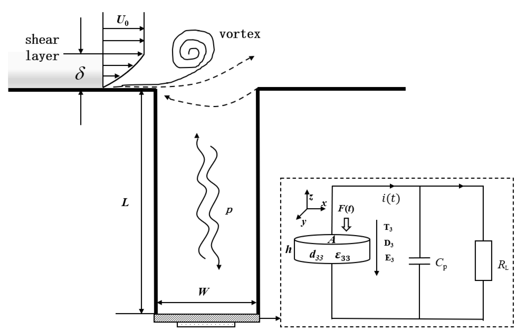
2. Working Principle of Energy Harvesting Device

The principle of generating power by combining the cavity flow-induced oscillation with the piezoelectric technology is shown in Figure 1. The energy harvesting device is simply composed of a cavity and a piezoelectric transducer. The piezoelectric transducer is installed at the closed end of the resonant cavity. The fluid flows through the opening of the cavity, and its flow direction is perpendicular to the cavity. A gas flow with one-way kinetic energy has extensive sources, such as gas flow in pipelines, gas flow around transportation tools and engineering facilities, and natural wind.
As shown in Figure 1, when gas flow passes over the cavity opening, the shear layer separates at the upstream edge. Affected by unsteady shear stress, the shear layer rolls up and periodically forms vortices, and then impinges on the downstream edge of the cavity, which can also be called fluid-dynamic oscillation. The shear layer oscillation acts on the stagnant gas in the deep cavity, and then induces the acoustic oscillation due to the gas compressibility. Under certain velocity and structural conditions, the coupling of the standing wave acoustic oscillation in the cavity and the fluid-dynamic oscillation of the shear layer results in self-sustained oscillations. The shear layer is physically equivalent to an amplifier. The acoustic resonant modes and the length of the cavity determine the oscillation frequency [17]. In this process, one-way gas flow with significant kinetic energy is transformed into oscillating flow in the cavity. The essence of the process is transferring fluid kinetic energy to acoustic energy. The piezoelectric transducer installed in the cavity vibrates under the excitation of acoustic waves, while acoustic energy is further converted to electrical energy.
The standing wave acoustic field is built when stable oscillations appear inside the cavity. Acoustic resonators generally include a half-wave type, a quarter-wave type, and a Helmholtz type. The cavity shown in Figure 1 belongs to the quarter-wave type. The closed end of the cavity includes the pressure wave antinodes, and the opening of the cavity always holds the pressure node. The acoustic oscillation frequency fm can be expressed as fm = mc/(4LR), where m represents the acoustic mode, c is the acoustic velocity, and LR is the length of cavity. According to the boundary conditions of a standing wave acoustic field, there only exist odd acoustic modes in the resonator tube. One, two, or three pressure wave antinodes are inside of the cavity when acoustic fields are at the first, third, and fifth acoustic modes, respectively. When m = 1, the length of the cavity is roughly equivalent to one-quarter of the wave length. The specific acoustic mode is determined by multiple oscillation conditions, such as gas flow velocity, cavity length and shape, etc.
The process of converting acoustic energy to electrical energy involves making use of piezoelectric material’s positive piezoelectric effect: that is, electrode surfaces become charged when force is applied to the piezoelectric material in a certain direction. The transducer is clapped at the closed end of the cavity in the form of electrode surfaces parallel to the cavity end face. The polarization direction of the transducer is perpendicular to the electrode surfaces, which are also forced surfaces. Therefore, thickness stretching mode is suitable for describing power outputting characteristics of the transducer.
Based on the piezoelectric transducer’s theoretical model, the transducer is forced by the alternating pressure, F(t) = Fac sin(ωt), provided by the acoustic field in the cavity; Fac is the maximum force that the acoustic field can supply by the pressure amplitude; and ω is angular frequency. In addition to the electrode surfaces, the rest surfaces of the transducer are free; the first piezoelectric equation is written as D3(t) = d33T3(t) + ε33E3(t), where d33 is the piezoelectric constant, ε33 is the dielectric constant, T3(t) is the stress of the piezoelectric transducer, and E3(t) is the electric field strength between the two electrode surfaces. The resonant frequency is mainly determined by the dynamic characteristics of the transducer. When the acoustic oscillation frequency is close to the resonant frequency, the efficiency of the piezoelectric system is optimal.

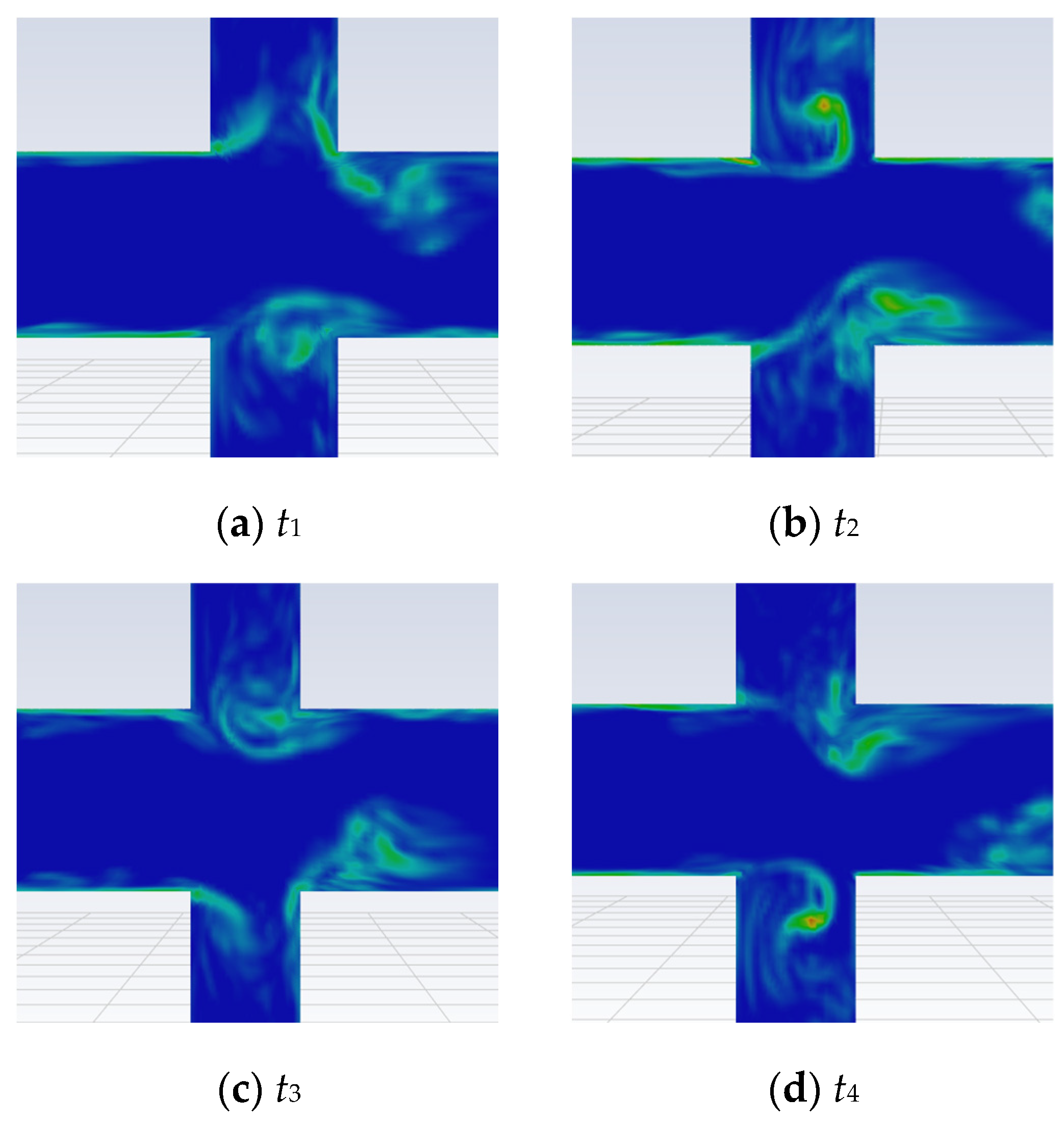
3. Flow Field of Fluid-Resonant Oscillation

Flow and acoustic characteristics are mainly studied by the computational fluid dynamics method. According to previous studies [15], the simulation results based on three-dimensional models agree with experimental results in terms of acoustic characteristics and hydrodynamic characteristics. Acoustic fields in different acoustic modes are analyzed. The development of vortices at the opening of the cavity is crucial for the acoustic oscillation inside the cavity. Vortices in different hydrodynamic modes occur. A particle image velocimetry experiment with a method of schlieren presented the vortex shedding phenomenon at the cavity opening [18]. The simulated vorticity distribution confirms this vortex shedding process.
Large-eddy simulation (LES) of a turbulence model was used to simulate flow and acoustic oscillation in the cavity configuration. The working fluid was ideal air at normal temperature and pressure. The inlet boundary was the Dirichlet boundary condition. The inlet pressure was set according to different gas flow velocities. The outlet pressure was calculated in such a way that the outlet radial velocity was neglected. No-slip boundary conditions were applied to walls. A finite volume method was employed to discretize the governing equations, a bounded central differencing method was used to discretize the momentum equation, and the density and energy equations were both discretized by a first-order up-wind method. These discretized equations were solved with an iteration time step of 10−5 s. When the pressure wave at the cavity end was stabilized, the calculation was complete.
The numerical simulation focused on the flow field of the cavity opening when the fluid-resonant oscillation occurred. Figure 2 shows the vorticity distribution at the opening of the cavity in an acoustic period when U0 = 29 m/s. The structural change from the wall to an opening induces the fluid to periodically form vortices. The vortex sheds from the upstream edge of the cavity opening, grows, and finally travels across the opening of the cavity when another vortex begins forming at the upstream edge. Within limited ranges of flow velocity, the vortex period is the same as the acoustic period. This phenomenon indicates that the vortex shedding behavior is phase-locked with the pressure wave variation. The number of vortices formed at the cavity opening is expressed as the hydrodynamic mode h. As shown in Figure 2, one vortex appears at the cavity opening with the first hydrodynamic mode (h = 1). When h = 2, two consecutive vortices simultaneously occur, so the time needed by a vortex to travel through the cavity opening is about two oscillation periods.
The acoustic oscillation is excited by the instability of the shear layer. The structure and velocity conditions under which the oscillation occurs and the intensity of acoustic oscillation are determined by the coupling characteristics between the shear layer and the acoustic field. The hydrodynamic characteristics and acoustic characteristics were linked together by Strouhal number St = fm·Weff/U0, where Weff is the effective diameter of the cavity opening. The term Weff/U0 indicates the time for the gas flow to pass the opening of the cavity. Then, the Strouhal number represents the ratio of the time the gas flow takes to pass the opening of the cavity to the acoustic pressure period. The acoustic oscillations only occur in certain regions of the Strouhal number.

4. Results and Analyses

4.1. Experimental Setup

Figure 3 is a schematic diagram of the experimental setup [16]. A centrifugal air fan controlled by an inverter was used as a gas source, which was able to provide a variable gas velocity. A buffer tank and several rectifier screens were installed in pipes in order to uniformly distribute the flow. A thermal mass flow meter (model 6444 supplied by Testo AG) measured the gas flow rate. The measurement accuracy of flow rate was 1 Nm3/h. The system pressure was measured with a pressure sensor (model 1501A02EZ15V45GPSI supplied by PCB Piezotronics, Depew, NY, USA installed at the cavity opening. Two deep cavities were symmetrically installed. A pressure sensor (model 106B51 supplied by PCB Piezotronics, Depew, NY, USA) at the closed end of one cavity was used to measure dynamic pressure, which had a nominal sensitivity of 1000 mV/psi. The diameter of the cavity was 32 mm. The length of the cavity was 190 mm or 480 mm. The PZT transducer was installed at the closed end of another cavity. The data acquisition system mainly included a data acquisition card (PCI-6220 supplied by National Instruments) and a terminal box (SCB-68 supplied by National Instruments).

4.2. Acoustic Field of the Cavity

Figure 4 shows the pressure waveform at the closed end of the cavity when U0 = 50.35 m/s. The closed end of the cavity is a pressure antinode in the standing acoustic field. The oscillation at this velocity is steady and has a high intensity; hence, the waveform is sinusoidal. The dominant frequency is 495 Hz with m = 1.
The pressure amplitude at the closed end of the cavity varying with flow velocity is shown in Figure 5. When the cavity length LR = 190 mm, acoustic fields maintained the first acoustic mode (m = 1) in the ranges of flow velocity of 11.6–17.9 m/s and 27.1–51.1 m/s. When the cavity length was LR = 480 mm, the first acoustic mode (m = 1) with flow velocity ranged from 12.6 to 6.1 m/s, the third acoustic mode (m = 3) ranged from 18.9 to 20.1 m/s and 34.2 to 51.3 m/s, and the fifth acoustic mode (m = 5) ranged from 29.1 to 33.1 m/s, which were extraordinarily notable. When the flow velocity changed, the acoustic mode discontinuously changed stepwise. The next section about the Strouhal number will illustrate the reason for and the importance of this velocity range. By comparison, the cavity with a length of 190 mm had much larger acoustic amplitudes than that with a length of 480 mm. When the cavity length was 190 mm, the maximum pressure amplitude of 15.54 kPa was achieved.
Based on vortex-sound theory [19,20], Howe indicated that the time average of the acoustic power Psource, generated by the vortices at a low Mach number can be calculated by
P source = ρ v ( ω × υ ) u d V
where ρ is the gas density, the vorticity ω is defined by ω = × υ , the acoustic velocity u is defined as the unsteady irrotational part of the velocity field, and V is the volume containing the vorticity field. The acoustic oscillation is self-sustained if the integral of acoustic power over an acoustic cycle is positive [21]. The whole acoustic power loss is usually divided into three parts: visco-thermal acoustic dissipation, radiation loss, and acoustic load. The acoustic load is usually installed at the end of the resonator, such as with a PZT transducer and thermoacoustic element. When the acoustic field is established, the acoustic power generated by the vortices can be estimated using the energy balance method:
Psource= Pv-th + Prad + Pload
When acoustic waves propagate in the cavity, some acoustic power is dissipated by the viscous and thermal effects between the gas and the wall. The visco-thermal acoustic dissipation Pv-th is given by [22]
P v t h = 1 4 ( P a c P 0 ) 2 ρ c 3 γ 2 π 2 R [ σ k ( γ 1 ) ( 1 + 2 R ω c π ) + σ v ]
where γ is the specific heat ratio, ω is the angular acoustic frequency, R is the cavity radius, Pac is the acoustic pressure amplitude, and P0 is the mean pressure. The viscous penetration depth is defined as σ v = 2 μ / ω ρ , where μ is the gas viscosity. The thermal penetration depth is defined as σ k = 2 κ / ω ρ c p , where κ is the gas thermal conductivity, and cp is the gas isobaric heat capacity.
According to the dimensionless acoustic pressure amplitude ua/U0, Bruggeman et al. [23] distinguished three levels of acoustic oscillation: small acoustic amplitude (ua/U0 < 10−3), moderate amplitude (10−3 < ua/U0 < 10−1), and high amplitude (ua/U0 = O(1)). ua is the amplitude of the acoustic velocity inferred from u a = p ac / ρ c . The acoustic oscillation in the present study belongs to the range of moderate-to-high amplitude. So, nonlinear effects become so significant that the acoustic field strongly influences vortices’ generation. Higher harmonics form due to the nonlinearity, and the acoustic energy radiates, from the opening of the cavity [17]. This part of energy loss is known as radiation loss Prad [24]:
P r a d = ρ c 3 π 2 ( γ + 1 ) 2 A 256 γ 4 ( p L R p m ) 4
The visco-thermal acoustic dissipation, radiation loss, and dimensionless acoustic pressure amplitude vary with Strouhal numbers as shown in Figure 6. When the length of the cavity is 190 mm, as shown in Figure 6a,b, acoustic oscillations occurring with the flow velocity ranges of 27.1–51.1 m/s and 11.6–17.9 m/s in Figure 5 belong to Zone A (0.24 < St < 0.45) and Zone B (0.61 < St < 0.75), respectively. The hydrodynamic mode of acoustic oscillations in Zone A and Zone B is h = 1 and h=2, respectively; this is also proven by the previous simulation results. The dimensionless acoustic pressure amplitude of the first hydrodynamic mode is highest. In Zone A, the visco-thermal acoustic dissipation is relatively high due to the large pressure amplitude. Meanwhile, the radiation losses sharply increase due to strong nonlinear effects when ua/U0 > 10−1. In Zone B, the nonlinear effects are neglected due to the low dimensionless acoustic pressure amplitude (ua/U0 < 10−3), so the radiation losses are nearly zero, and the visco-thermal acoustic dissipation is relatively weak. Unlike the radiation loss, the visco-thermal acoustic loss occurs so long as the acoustic oscillation exists. When the cavity length increases to 480 mm, as shown in Figure 6c,d, the oscillation intensity markedly decreases, and the radiation loss is very weak.

4.3. Output Characteristics of the PZT Transducer

The transducer basically consisted a 0.3 mm thick PZT-5 ceramic square plate sandwiched between several layers of FR4-based PCBs. The overall dimensions were 28.5 mm long, 28.5 mm wide, and 1.5 mm thick. The transducer was clapped in the closed end of the cavity by the flange. The output characteristics of the PZT transducer’s open circuit voltage were studied and compared in different lengths of the cavity. The piezoelectric transducer output sinusoidal voltage fluctuating with sinusoidal pressure. In addition, there was a phase difference between pressure and voltage. The instantaneous output voltage was u 0 ( t ) = p a c sin ( ω t + φ ) .
The output characteristics were tested when the cavity length was 190 mm with a flow velocity of 47.7 m/s. The acoustic pressure and output voltage waveforms are shown in Figure 7. As shown, the pressure of the standing wave acoustic field sinusoidally varies with an amplitude of 10.7 kPa and a frequency of 495 Hz. The output voltage produced by the PZT transducer varies in the same manner with an amplitude of 0.26 V. The phase difference between the output voltage wave and the pressure wave is 9.4°. The delay is caused by the coupling of the PZT transducer and the characteristics of the acoustic field.
The output voltage characteristics of the PZT transducer are mainly affected by the characteristics of the acoustic field. Shown in Figure 8, the output voltage amplitudes linearly fit with the acoustic pressure amplitudes. With a cavity length of 190 mm, the frequency of acoustic oscillations is 490 Hz, which is in the first acoustic mode. The conversion ratio of output voltage to acoustic pressure is 18.4 mV/kPa by one order of linear fit. With a cavity length of 480 mm, when the acoustic field is in the first, third, and fifth modes, corresponding to acoustic frequencies of about 180 Hz, 550 Hz, and 910 Hz, the conversion ratios are 8.0 mV/kPa, 17.3 mV/kPa, and 23.4 mV/kPa, respectively. The theoretical resonant frequency of the PZT transducer is usually much higher than the frequency of the acoustic field. The conversion efficiency increases with acoustic frequency because of the electroacoustic coupling characteristics.
Actually, the acoustic field, the electrical field, and the external circuit formed a complex system with significant coupling. The energy conversion characteristics and efficiency were determined by the parameters of the electroacoustic coupling system. The present transducer was nonoptimized so that the efficiency of acoustic–electric conversion was relatively low. In addition, the actual surface of the PZT transducer effectively contacting with the acoustic field was a round face with a small radius of 7.5 mm due to the flange installation design. Therefore, a further optimization study on the cavity dimensions, transducer performance, and external electric design is crucial for improving energy harvesting efficiency.

5. Conclusions

The conversion process from fluid kinetic energy to electric energy was realized by combining the flow-induced oscillation phenomenon with piezoelectric technology. The flow-resonant oscillation in the cavity was numerically simulated. The coupling mechanism between the hydrodynamic and acoustic characteristics was analyzed. The influence of flow velocity and cavity dimension on the frequency and amplitude of acoustic oscillation was explored. The energy loss mechanism in this type of acoustic field was analyzed by calculating the visco-thermal acoustic dissipation and the radiation loss. The results showed that acoustic oscillations with mono-frequency occurred under certain speed conditions, which could drive the piezoelectric energy converter to output a voltage with stable frequency. The first acoustic mode and the first hydraulic mode helped to achieve an acoustic field with higher intensity, with flow velocity 27.1–51.1 m/s when the cavity length was 190 mm. The maximum open circuit voltage achieved was 0.286 V when the pressure amplitude was 15.34 kPa. The preliminary transducer performance limited the efficiency of acoustic–electric conversion. Further optimization should focus on cavity dimensions, transducer performance, and external electric design. This method not only enriches the utilization of environmental fluid kinetic energy, but is also expected to realize passive power supply in micro wireless electronic equipment on special occasions, such as low power consumption, long distance, and low maintenance.

Author Contributions

Conceptualization, Y.X. and D.S.; methodology, Y.X. and D.S.; validation, Y.X. and J.Y.; data curation, Y.X.; writing—original draft preparation, Y.X. and J.Y.; writing—review and editing, Y.X. and J.Y.; supervision, D.X.; project administration, Y.X.; funding acquisition, Y.X. and D.S. All authors have read and agreed to the published version of the manuscript.

Funding

This research was funded by Natural Science Foundation of Zhejiang Province (LQ19E060005) and the Fundamental Research Funds for the Provincial Universities of Zhejiang (2021YW50).

Data Availability Statement

Not applicable.

Conflicts of Interest

The authors declare no conflict of interest.

References

  1. Rostami, A.B.; Armandei, M. Renewable energy harvesting by vortex-induced motions: Review and Benchmarking of Technologies. Renew. Sust. Energ. Rev. 2017, 70, 193–214. [Google Scholar] [CrossRef]
  2. Cao, D.X.; Wang, J.R.; Guo, X.Y.; Lai, S.K.; Shen, Y.J. Recent advancement of flow-induced piezoelectric vibration energy harvesting techniques: Principles, structures, and nonlinear designs. Appl. Math. Mech. 2022, 43, 959–978. [Google Scholar] [CrossRef]
  3. Wang, J.L.; Geng, L.F.; LIN, D.; Zhu, H.J.; Yurchenko, D. The state-of-the-art review on energy harvesting from flow-induced vibrations. Appl. Energy 2020, 267, 114902. [Google Scholar] [CrossRef]
  4. Bernitsas, M.M.; Raghavan, K.; Ben-Simon, Y.; Garcia, E.M.H. VIVACE (Vortex Induced Vibration Aquatic Clean Energy): A New Concept in Generation of Clean and Renewable Energy from Fluid Flow. J. Offshore Mech. Arct. Eng. 2008, 130, 41101. [Google Scholar] [CrossRef]
  5. BioPower Systems Nears Trials. Available online: https://www.theswitchreport.com.au/business/biopower-systems/ (accessed on 10 September 2014).
  6. Liu, F.; Phipps, A.; Horowitz, S.; Ngo, K.; Cattafesta, L.; Nishida, T.; Sheplak, M. Acoustic energy harvesting using an electromechanical helmholtz resonator. J. Acoust. Soc. Am. 2008, 123, 1983–1990. [Google Scholar] [CrossRef] [PubMed]
  7. Phipps, A.; Liu, F.; Cattafesta, L.; Sheplak, M.; Nishida, T. Demonstration of a wireless, self-powered, electroacoustic liner system. J. Acoust. Soc. Am. 2009, 125, 873–881. [Google Scholar] [CrossRef] [PubMed]
  8. Hernandze, R.; Jung, S.; Matveev, K.I. Acoustic energy harvesting from vortex-induced tonal sound in a baffled pipe. Proc. Inst. Mech. Eng. Part C J. Eng. Mech. Eng. Sci. 2011, 225, 1847–1850. [Google Scholar] [CrossRef]
  9. Zou, H.J.; Chen, H.J.; Zhu, X.G. Piezoelectric energy harvesting from vibration induced by jet-resonator system. Mechatronics 2015, 26, 29–35. [Google Scholar] [CrossRef]
  10. Hamdan, C.; Allport, J.; Sajedin, A. Piezoelectric power generation from the vortex-induced vibrations of a semi-cylinder exposed to water. Energies 2021, 14, 6964. [Google Scholar] [CrossRef]
  11. Zhao, K.; Zhang, Q.; Wang, W. Optimization of galloping piezoelectric energy harvester with v-shaped groove in low wind speed. Energies 2019, 12, 4619. [Google Scholar] [CrossRef] [Green Version]
  12. Binyet, E.M.; Chang, J.-Y.; Huang, C.-Y. Flexible Plate in the Wake of a Square Cylinder for Piezoelectric Energy Harvesting—Parametric Study Using Fluid–Structure Interaction Modeling. Energies 2020, 13, 2645. [Google Scholar] [CrossRef]
  13. Rockwell, D.; Naudascher, E. Review-self-sustaining oscillations of flow past cavities. J. Fluids Eng. 1978, 100, 152–165. [Google Scholar] [CrossRef]
  14. Slaton, W.V.; Zeegers, J.C.H. An aeroacoustically driven thermoacoustic heat pump. J. Acoust. Soc. Am. 2005, 117, 3628–3635. [Google Scholar] [CrossRef] [PubMed]
  15. Yu, Y.S.W.; Sun, D.; Zhang, J.; Xu, Y.; Qi, Y. Study on a Pi-type mean flow acoustic engine capable of wind energy harvesting using a CFD model. Appl. Energy 2017, 189, 602–612. [Google Scholar] [CrossRef]
  16. Sun, D.; Xu, Y.; Chen, H.; Shen, Q.; Zhang, X.; Qiu, L. Acoustic characteristics of a mean flow acoustic engine capable of wind energy harvesting: Effect of resonator tube length. Energy 2013, 55, 361–368. [Google Scholar] [CrossRef]
  17. Dequand, S.; Hulshoff, S.J.; Hirschberg, A. Self-sustained oscillations in a closed side branch system. J. Sound Vibr. 2003, 265, 359–386. [Google Scholar] [CrossRef]
  18. Peters, M. Aeroacoustical Sources in Internal Flows; Technical University at Eindhoven: Eindhoven, The Netherlands, 1993. [Google Scholar]
  19. Howe, M.S. Theory of Vortex Sound; Cambridge University Press: Cambridge, UK, 2003. [Google Scholar]
  20. Howe, M. Acoustics of Fluid-Structure Interactions; Cambridge University Press: Cambridge, UK, 1998. [Google Scholar]
  21. Ziada, S.; Shine, S. Strouhal numbers of flow-excited acoustic resonance of closed side branches. J. Fluids Struct. 1999, 13, 127–142. [Google Scholar] [CrossRef]
  22. Swify, G.W. Thermoacoustic engines. J. Acoust. Soc. Am. 1998, 84, 1145–1180. [Google Scholar] [CrossRef]
  23. Bruggeman, J.C.; Hirschberg, A.; Van Dongen, M.E.H.; Wijnands, A.P.J.; Gorter, J. Flow Induced Pulsations in Gas Transport Systems: Analysis of the Influence of Closed Side Branches. J. Fluids Eng. 1989, 111, 484–491. [Google Scholar] [CrossRef]
  24. Slaton, W.V.; Zeegers, J.C.H. Acoustic power measurements of a damped aeroacoustically driven resonator. J. Acoust. Soc. Am. 2005, 118, 83–91. [Google Scholar] [CrossRef] [PubMed]
Figure 1. Working principle diagram.
Energies 15 09191 g001
Figure 2. Vortex shedding process in an acoustic period (m = 1, h = 1).
Energies 15 09191 g002
Figure 3. Schematic diagram of experimental setup.
Energies 15 09191 g003
Figure 4. Pressure waveform and spectrum analysis.
Energies 15 09191 g004
Figure 5. Pressure amplitudes at the closed end of cavity varying with flow velocity.
Energies 15 09191 g005
Figure 6. Variations in the visco-thermal acoustic loss Pv-th, the radiation loss Prad, and the dimensionless acoustic pressure amplitude ua/U0 versus the Strouhal number. (a,b) LR = 190 mm; (c,d) LR = 480 mm.
Energies 15 09191 g006
Figure 7. Synchronized waveforms of acoustic pressure and output voltage.
Energies 15 09191 g007
Figure 8. Output voltage amplitudes of transducer varying with the pressure amplitudes at the closed end of the cavity.
Energies 15 09191 g008
Publisher’s Note: MDPI stays neutral with regard to jurisdictional claims in published maps and institutional affiliations.

