Review

Small-Scale Hybrid and Polygeneration Renewable Energy Systems: Energy Generation and Storage Technologies, Applications, and Analysis Methodology

Department of Sustainable Energy Development, Faculty of Energy and Fuels, AGH University of Science and Technology, 30-059 Krakow, Poland
*
Author to whom correspondence should be addressed.
Energies 2022, 15(23), 9152; https://doi.org/10.3390/en15239152
Submission received: 31 October 2022 / Revised: 25 November 2022 / Accepted: 29 November 2022 / Published: 2 December 2022
(This article belongs to the Special Issue Power System Dynamics and Renewable Energy Integration)

Abstract

:
The energy sector is nowadays facing new challenges, mainly in the form of a massive shifting towards renewable energy sources as an alternative to fossil fuels and a diffusion of the distributed generation paradigm, which involves the application of small-scale energy generation systems. In this scenario, systems adopting one or more renewable energy sources and capable of producing several forms of energy along with some useful substances, such as fresh water and hydrogen, are a particularly interesting solution. A hybrid polygeneration system based on renewable energy sources can overcome operation problems regarding energy systems where only one energy source is used (solar, wind, biomass) and allows one to use an all-in-one integrated systems in order to match the different loads of a utility. From the point of view of scientific literature, medium- and large-scale systems are the most investigated; nevertheless, more and more attention has also started to be given to small-scale layouts and applications. The growing diffusion of distributed generation applications along with the interest in multipurpose energy systems based on renewables and capable of matching different energy demands create the necessity of developing an overview on the topic of small-scale hybrid and polygeneration systems. Therefore, this paper provides a comprehensive review of the technology, operation, performance, and economical aspects of hybrid and polygeneration renewable energy systems in small-scale applications. In particular, the review presents the technologies used for energy generation from renewables and the ones that may be adopted for energy storage. A significant focus is also given to the adoption of renewable energy sources in hybrid and polygeneration systems, designs/modeling approaches and tools, and main methodologies of assessment. The review shows that investigations on the proposed topic have significant potential for expansion from the point of view of system configuration, hybridization, and applications.

1. Introduction

Among the greatest challenges of the modern world, the goal of reducing greenhouse gas emissions produced by anthropogenic activity stands out the most. One of the tasks set for all countries in the world is to achieve zero-carbon energy generation by 2050 [1]. For many years, international and national organizations have been persuading the private and public sector to switch to renewable energy sources (RES), increase the efficiency of energy generation from conventional sources, or phase them out altogether. Unfortunately, this is a very difficult goal to achieve.
Getting energy from unconventional sources is not only a modern idea. Large hydroelectric power plants have been popular around the world since the beginning of the last century [2], and the conversion of wind energy into mechanical power, for example, in windmills, has been known for hundreds of years [3]. Today, solar power plants and wind farms are commonplace, and the first part of the 21st century has seen a big focus on distributed energy [4]. Nowadays, many homes are equipped with small photovoltaic power plants or wind turbines, and this fact is primarily influenced by development and ongoing RES application and research. One of the main directions of development is to increase the efficiency of energy generation or search for new solutions. In particular, this can involve the conversion of renewable energy itself [5,6] or individual components of the installation [7,8,9]. Despite its great popularity, energy generation from renewable sources is characterized by several disadvantages compared to conventional sources [10]. The most significant of these are the instability of operation [11] and the economic unprofitability of individual solutions [12].
The efficiency of most ways of producing energy from RES is closely related to weather conditions. As a result, the exact duration of their operation cannot be accurately predicted, as occurs in the case of photovoltaic plants [13,14], where during operation, a peak in energy production is observed during the sunny hours, while there is almost null or no generation in the evenings or at night. In addition, it is necessary to take into account the period of the year and the weather of each day. These facts would translate into significant limits and disadvantages if the energy mixes of entire countries were based mainly on PV. We live in a time when even a temporary blackout would cause huge disservices to systems and property damage or could lead to dangerous situations that put lives and health at risk. However, there are various ways to solve this problem. The first is to introduce a technology characterized by stable operation into the power system based on RES. This could be, for example, a system based on biomass combustion [15] or nuclear power [16]. The second way can be to secure against a possible drop in production by creating a system [17] based on different RES technologies, whose projected production hours during the day are complementary. This way can also be further improved by using energy storage technologies [18,19]. Despite such possibilities, adapting such a system to the national power grid is not an easy operation from the technical and grid management points of view. However, thanks to recent technological advances and research, they are finding very high potential in the application of distributed energy.
A system that produces energy from at least two different renewable sources is called a hybrid renewable energy system (HRES) [20,21,22]. It can be based on the simultaneous generation of useful energy from solar, wind, hydro, or geothermal energy sources. A biomass energy conversion system can also be used for this purpose. Obviously, energy taken from storage can be considered a source of renewable energy as well, once the storage component has been charged using RES. As mentioned earlier, HRES has a number of advantages including the most important one, which is the stabilization of the operation of the entire system. An example is a photovoltaic (PV) system operating simultaneously with a wind turbine [23,24].
When using renewable energy sources in distributed power generation, it is very important to match the system to the user’s needs. To show that, two parameters should be highlighted: the self-consumption rate [25] and the ratio of energy demand coverage [26]. As for the first parameter, it should be understood as the ratio of energy directly used by the user to the total energy produced from RES. The values of this indicator depend on several parameters, including the location of the installation, the energy demand of the user, the output of the system itself, or weather conditions. An example would be a photovoltaic system installed on a typical single-family house. For example, a value of this indicator at 25% means that of all the energy produced by the PV, only 25% was used directly by the user, while the rest was wasted or supplied to the electric grid. The second parameter can be calculated as the ratio of energy extracted from RES to the total demand for this type of energy. These values are usually given for a longer period of time. For example, if user has an annual demand for electricity equal to 5000 kWh and a photovoltaic installation from which is possible to self-consume 2000 kWh directly, this means that energy demand coverage in this case will be 40%.
An ideal HRES system should be characterized by 100% self-consumption and 100% energy demand coverage. This would result in zero losses of generated energy and a negligible risk of running out of energy, only due to the failure of system components. Unfortunately, this ideal scenario is practically impossible to achieve due to the technical constraints of the devices, variability of user demand, and economic limits of the potential investments. The focus, however, should be on analyses showing the possibilities of better and better systems, which are as close as possible to the ideal ones.
When generating one type of energy, there is always some loss in the system. This can be seen in the case of electricity generation with a biomass or coal boiler Rankine cycle system. In this case, energy is lost through a pipe, mainly due to the dissipation of heat by the condenser. In the early 19th century, it was realized that after leaving the turbine, water still has a lot of useful energy that can be recovered [27]. It can be used, for example, to heat domestic hot water. A plant that simultaneously generates electricity and useful heat is called a combined heat and power (CHP) plant, and the process itself is called cogeneration [28,29,30]. Simultaneous generation of two types of energy is very economical and increases the efficiency of the entire plant compared to a separated production of energies. Chill generators in the form of sorption chillers can also be included in CHP systems [31,32]. In this case, the process that allows the simultaneous generation of three types of energy is called trigeneration. Furthermore, when the generation of energy is also coupled with the production of useful by-products, we are referring to polygeneration [33,34,35]. Passing from cogeneration to polygeneration, it is possible to observe that the grade of energy utilization significantly increases, and this may also have significant effects on the effectiveness of the energy systems adopted.
Each of the aforementioned methods of increasing the efficiency of plant operation can be used in distributed power generation. Maximization of energy yield and achievement of the highest possible efficiency rates are essential aspects of small hybrid RES-based polygeneration systems. Currently, great attention is paid to the optimization of such systems. It is necessary to select energy sources appropriately, and if necessary, to select energy storage technologies. The most important features of such a system should be maximum autonomy and efficiency, and thus cost-effectiveness. It is the second feature that is usually the biggest problem to be solved.
The present review aims to provide a comprehensive overview of recent advances regarding small-scale hybrid renewable energy systems. In particular, the review is focused on the technical aspects of the different energy generation and storage technologies, their use in HRES, and approaches and tools used in the design of integrated HRES. The review is organized as follows. Firstly, the available technologies for the production of energy are presented, and after that, the possibilities of energy storage are introduced. The review continues with a description of the different configurations of HRES technologies and concludes with the presentation of methods to investigate HRES. In the end, some general conclusions regarding small-scale HRES are given in order to summarize the review.

2. Available Renewable Energy Technologies

Several technologies are used to generate energy in HRES depending on the type of energy to be generated—electrical or thermal—or on the availability of renewable energy sources to be used by the system. The presented technologies are the ones that are conventionally used in HRES to produce energy from the specific renewable energy source and are commercially available on the market. The technologies are:
-
photovoltaic modules;
-
solar collectors;
-
wind turbines;
-
water turbines;
-
biomass units;
-
heat pumps.

2.1. Photovoltaic Systems

When considering the world’s energy production in 2021 from renewable energy sources, photovoltaic installations rank third in terms of installed capacity [36]. Recent reports show that this value has increased sevenfold between 2010 and 2020 indicating very dynamic growth and suggesting ever-increasing installed capacity in the future. The very high popularity and affordability of this technology are contributing to its continuous development and thus increasing its efficiency. Photovoltaic installations are very often used as a key energy source in small HRES [37]. The basic solution is to use standard first-generation modules and place them on the available surfaces of the utility being powered. When planning even the most basic photovoltaic installation, it is important to keep in mind several factors that affect its operation. This directly includes the geographic location of the facility being powered, and thus the angle of the modules from the floor [13]. The efficiency of an installation located in Scandinavian countries will be different from one in the vicinity of the equator. The difference is primarily due to the different values of average horizontal irradiation in these locations, but also the average annual air temperature. The higher it is, the lower the efficiency of PV cells [38]. This problem is being addressed by the latest research on module cooling systems to enhance their performance. Praveenkumar et al. [39] showed that it is possible to integrate a PV module with a heat pipe. The research indicated that this decreased the module’s surface temperature by an average of 6.72 °C on a sunny day. The temperature reduction resulted in an increase in cell efficiency of about 2.98% over the comparison module. A different approach was followed by Sornek et al. [40] in designing a system to cool a PV module by spraying its surface with water. Their research showed that this procedure allowed an increase in the maximum instantaneous power of the modules by about 10% compared to the comparative system.
A PV system can be placed not only on the roof or ground—a very popular approach in Asia [41] is floating PV systems. This solution not only saves space for the installation by using a body of water but also increases energy production by cooling the PV panels [42]. Studies [43] show that a floating installation has a lower average surface temperature of the modules by 2–4% compared to an installation placed on the ground. In addition, the authors pointed out that this method of installation reduces the intensity of water evaporation in the water tank used. In recent years, an increasing emphasis on research on photovoltaic cells of the second, third, or fourth generation can be observed [44]. However, from the point of view of commercial applications, they are characterized in most cases by lower efficiency than first-generation solutions except for multijunction cells, the cost of which prevents their cost-effective use for most small-scale polygeneration systems.
Attention should also be paid to technology using focused solar radiation. Using mirrors or lenses, it is possible to increase the efficiency of electricity production from a photovoltaic cell. This technology is called concentrated photovoltaics (CPV). However, a review of this technology [45] indicates that this solution is not valid for receiving only electricity, due to the occurrence of excessive temperatures. It is advisable to additionally dissipate effectively or use the heat produced.
When considering the operation of a statistical PV system, the largest energy yield losses are associated with the shading or fouling of individual PV cells [46]. This is due to the characteristics of connecting modules in series with each other in a classical solution. This results in small values of current with voltage increase, which positively affects the safety of the installation and limits the ohmic losses on the solar cables. In order to make the entire photovoltaic circuit operate at uniform current parameters, a DC/DC voltage converter is present at each PV installation. It is designed to track the maximum power point of the circuit and adjust the installation voltage to achieve it. This component is called a maximum power point tracker (MPPT). With this configuration, partial shading of the installation or even of a few cells of one module negatively affects the performance of the entire installation. To cope with this problem, more and more research is being dedicated to the proper configuration of MPPT control. There are many options for tracking the point of maximum power [47,48], including: traditional—based on direct measurements of voltage and current; mathematical modeling—showing the locations of the point of maximum power; and intelligent algorithms—allowing the creation of a neural network that is taught to look for the right parameters to obtain the best results. Photovoltaic installations have plenty of advantages that demonstrate their versatility of use in small-scale polygeneration systems. These include, first and foremost, the relative stability of operation under conditions of adequate insolation and low price.

2.2. Solar Collectors

The abovementioned photovoltaic modules are not the only way to use solar energy. Thermal solar collectors are also used for this purpose. The most common are classic flat-plate collectors, which have a layer that absorbs solar energy and a piping in which the working medium is heated. The heat is then transferred usually to a domestic water circuit. In addition to flat-plate collectors, tubular vacuum variants, which use heat pipes that allow the heating medium to move, are also popular. The adoption of a vacuum allows the absorber surface to be well insulated, resulting in less heat loss to the environment.
It is possible to integrate a solar collector with a photovoltaic module, creating a photovoltaic–thermal (PV/T) hybrid system [49], which allows not only the supply of electricity but also heat. The hybrid cogeneration approach to energy production increases the efficiency of the entire system. However, this solution requires suitable climatic conditions for profitable operation. Tracking the performance of existing installations [50] shows that, depending on the latitude, the thermal or photovoltaic part of the hybrid module has better performance. In addition, using such a system to heat water provides temperatures ranging from 40 °C to 60 °C, which typically limits the possibilities of its use in relatively low-temperature applications [51].
In the case of photovoltaic cells, the concentration of solar radiation is associated with large losses due to excessive temperature. For solar power systems, however, the possibility of achieving relatively high temperatures is key. Several types of collectors using concentrated solar radiation can be distinguished [52]: compound parabolic collectors [53], trough parabolic collectors [54], parabolic dishes [55,56], Fresnel lenses [57], and power towers [58]. Each of these differs in a number of factors, but comparisons should mainly be made on the basis of operating temperature, from which the appropriate solution can be selected to meet needs. Collectors operating on concentrated solar radiation are not often used with small-scale systems, so can be observed as large-scale solar farms.
In order to improve the performance of a collector system, there is a lot of research involving the proper adjustment of the water circulation system. This can be carried out in a direct way, i.e., the heating medium in the collector is water, which when heated flows directly into the building pipelines. The second option is a system in which a separate heating medium is present, flowing in a separate circuit near the collector and transferring energy to a second circuit with domestic water. The movement of the medium is typically assisted by circulating pumps and is rarely achieved by natural convection, taking advantage of the difference in fluid density at different temperatures. Optimization of the system can also involve selecting the most efficient heating medium [59,60] or locating heat storage. In most solar collector systems, tanks can be observed inside the building; however, especially on a small scale, external tanks sometimes integrated into the collector itself are popular. In countries with high temperatures, this can allow additional reheating of the water in such a tank [61].
Collector systems can serve as the main source of hot water in a hybrid system, but they are increasingly encountered at the same time as auxiliaries, which are mainly intended to reheat the circulating medium to improve the performance of the entire system [62]. These are not the most popular methods of obtaining thermal energy; however, under the right environmental circumstances, they can be a very good source of energy for small-scale polygeneration systems or as the main source of heat in large-scale systems [63].

2.3. Wind Turbines

Wind energy is the second-largest RES in the world [64]. Wind turbines are mainly used to generate energy from this source, and when considering this technology, the first classification points to turbines with vertical (VAWT) and horizontal (HAWT) axes of rotation. The first group can be divided into two basic types [65]. The first is the thrust type [66], which includes the Savonius rotor [5] and Sistan rotor [67], where blades are usually bowl-shaped. The rotation of turbines of this type is caused directly by the force of wind pressure. They are characterized by the lowest rotational speed and therefore the lowest power yield. The second type consists of turbines based on lift force, which requires the use of blades in the shape of airfoils, and this group can include the Darrieus turbine [68] or H-rotor [69]. They are characterized by a higher rotational speed, which is able to match or even exceed turbines with a horizontal rotation axis. Unfortunately, the big problem of this solution is the relatively high wind speed required to start operation. Nevertheless, it is possible to combine both types to reduce its value [70]. Due to their design, VAWTs always generate negative torque, which reduces their efficiency. One way to deal with negative torques is to use augmentation methods, which allow changing the direction, to a certain extent, of the wind flowing through the turbine [71].
The scientific literature indicates that it is possible to improve the efficiency of turbines with a vertical axis of rotation using elements that increase wind speed [65]. These could be a deflector plane or a diffuser using the Venturi effect. Also very promising are the results of studies of the usage of methods such as air currents near buildings [72] or suitably shaped terrain [73]. These methods allow wind turbines to be placed in urban centers or next to individual homes, demonstrating the possibilities of their usage in distributed energy. The possibilities are supported by the fact that VAWTs take up less space than HAWTs.
As concerns VAWT design details, Qiang Gao et al. [74] showed a novel approach to controlling the blade arrangement in a Darrieus turbine, which can also positively affect its operation. In the case of lift-based types, it is very important to choose the right shape of airfoils for the blades [75], which is also a vital aspect of designing turbines with a horizontal axis of rotation [74].
Because of their higher efficiency, HAWTs are the most popular among commercial applications. A significant number of wind farms are based on this technology. In addition to dimensions, they can differ in the number of rotor blades. The best choice turns out to be a three-blade turbine. It allows very high efficiency while minimizing noise and manufacturing costs. Considering a different number of blades, the performance of the turbines is close [76], with the single-blade rotor, which by shifting the center of gravity falls into a strong vibration, the most distant. As with VAWTs, the operation of this type of turbine can be improved with the use of diffusers, but one of the most prosperous ideas is to equip the rotors with systems designed to adjust the rotor blade arrangement according to wind parameters [77]. Changing the angle of attack is also important for safety reasons, such as in situations where the turbine must be stopped.
Both groups of wind turbines (VAWTs and HAWTs) can be installed on land or water. The second way may allow them to work better due to the absence of any obstacles and high wind speeds. For this purpose, turbines with a horizontal axis of rotation are best suited, as they can withstand higher overloads. There are studies [78] testifying to the possibility of creating floating wind farms. This would allow the use of waters too deep to place a foundation and could also minimize costs.
For all types of turbines, it is very important to choose the right material to create their blades. It must be light enough, but also strong enough to achieve the best performance. Most often composite materials (carbon and glass fibers) are used. However, this is one of the biggest problems for wind turbines because these materials are difficult to recycle. Initial research shows the possibility of using used rotor blades to make composite plates, which can be used to make structural components for bridges or buildings. Researchers [79] have shown that proper processing allows even higher strength than analogous plates created for this purpose.

2.4. Water Turbines

The use of the potential or kinetic energy of water to produce energy is the main RES worldwide [36]. From the point of view of technologies, the types of hydropower plants adopted are dammed [80] and pumped storage [81]. The first type involves restricting the flow of a river by damming the water, creating an artificial basin, and at the same time increasing the possibility of utilizing the high head to produce electricity. For this purpose, Francis [82] or Pelton [83] water turbines are used, depending on the available head of the water. The second type uses mainly the potential energy of water.
Hydropower plants may be used as a type of energy storage. In fact, when there is a peak of power production on the electrical grid coupled with a relatively low price of electrical energy, i.e., excess energy is produced and the energy is cheap, water from the lower reservoir can be pumped into the upper one, while when there is a peak of demand of energy in the grid and the price is relatively high, the water can be released into the lower reservoir, giving back the energy stored.
These types of turbines are rarely used for small hydropower plants [84]. For this purpose, a large proportion of other means of energy production, consisting of flow or tidal power plants, can be used. The first of these are located in rivers, where they use the kinetic energy of water to produce mechanical energy and then electricity. Historically, river mill wheels were used for these purposes. As of today, the best universal system cannot be directly selected. Depending on the case, it could be, for example, an Archimedes screw [85] or a Kaplan turbine [86]. Properly fitting a small hydropower plant into a given landscape is a very difficult task. One should keep in mind the relatively negative impact of such an installation on the environment. The construction of such a power plant can cause problems in fish migration, disturb the biological balance of the river or pollute the water itself. However, studies indicate that if a number of guidelines are followed and particular attention is paid to the development of the plant, these problems can be minimized [87,88].

2.5. Biomass Technologies

In the era of transitioning away from conventional energy sources, there is an increased search for zero-carbon alternatives. One possible method of clean energy generation is the combustion of biomass. Biomass can be defined as any organic substance of biological origin (vegetable or animal) available in the world. When using biomass processing technology, the most chosen biomasses are municipal waste, agricultural waste, vegetables, and energy crops [89], as well as wood in unprocessed form or pellet form. In addition, these biomass types can be converted into biogas or biofuels, which can have much better energy conversion parameters compared to the raw/origin material [90].
In addition to the type of fuel, different ways of burning biomass can be distinguished, depending on the scale of customer needs. For high-capacity units, fluidized beds [91] and grate boilers [92] are commonly used devices. The former has the highest efficiency, which derives from the characteristics of the combustion itself. Fuel is pulverized in the combustion chamber to form a slurry, with sand or ash particles adopted as inert material. For residential customers, the most popular way to obtain heat from biomass is by a fireplace. The installation can be adapted to transfer energy around the building, as well as to heat domestic water by burning wood in the fireplace [93,94].
Commercial biomass boilers are based on the use of wood or pellets, while in the case of using straw, batch boilers are often used. These boilers can be characterized by very high output (up to 1 MW), but there are also smaller units for a single household.
Multistage biomass combustion shows promising results [95]. This consists of drying, pyrolysis, oxidation, and reduction stages. By converting solid fuel into a gaseous state, higher efficiencies are achieved throughout the process. Recent studies indicate that despite the inclusion of biomass as a renewable energy source, emphasis should be placed on the development of cogeneration technologies that allow obtaining not only heat but also electricity or cooling from combustion [96].
Biomass combustion is one of the most popular methods of heat generation in distributed renewable energy applications. Households without access to district heating or the natural gas infrastructure most often use units that burn wood or pellets. It is worth noting that suitably adapted systems can be used to generate electricity. The heat generated by a biomass combustion unit is transferred to a substance that changes the state of matter or, in general, to the working fluid of a power cycle. It then drives a steam or gas turbine, which, connected by a shaft to a generator, produces electricity. However, this way of biomass use can be more efficient when it is coupled with a combined heat and power (CHP) approach. In such a CHP system, components that take off excess heat allow one to supply thermal energy to the user. Such a solution works well in large central CHP plants, but also in distributed power generation [97].

2.6. Heat Pumps

Currently, there are relatively few methods of heating buildings that are not connected to a district heating network. Focusing on the use of renewable energy sources, in addition to the solar or biomass conversion systems already discussed, heat pumps are becoming increasingly popular. The use of these devices, particularly in the distributed energy sector, is considered a critical method for decarbonizing heat production worldwide [98].
Their operation is based on extracting energy from a low-temperature source to a higher-temperature source. The whole process must be assisted by supplying external energy, such as electricity. Heat transfer is carried out by means of a working medium consisting typically of an organic fluid, which must have appropriate operating thermodynamic parameters depending on the temperature of the lower source [99]. The most important of these is the boiling point. The medium is supposed to receive heat in the evaporator, from a medium with a relatively low temperature.
The lower heat source can be a variety of different media. Often, it is the air surrounding the building [100]. Pump systems developed for this purpose have fans that allow heat transfer from the air to the working medium. The great popularity of this solution is directly due to its relative versatility. An air heat pump can be installed on a building in a variety of climatic conditions. The most stable operation of these devices is observed for ambient temperatures in the range of −3 °C–10 °C [101]; however, after appropriate adjustment of the operation of the units, optimal operation is observed even at temperatures down to −30 °C [102].
The lower source of the heat pump can also be the ground. Direct energy extraction from globally available deposits is often uneconomical and requires specific conditions [103]. Most often, small geothermal deposits have too low a temperature to heat domestic water and supply heating directly or generate electricity. This energy stored in the ground can easily be used in heat pump systems. The main advantage of these solutions is the relatively stable temperature of the lower source, which translates into better heating efficiency. Ground-source heat pump applications can be divided into two types: vertical or horizontal heat exchangers. The first [104] are based on drilling a borehole reaching typically from 30 to 100 m deep or more. This procedure is designed to ensure a lower heat source with the highest possible constant temperature. With depth, the temperature of the ground tends to be more constant over the year; however, at the same time the investment costs associated not only with digging the borehole itself but also with the circulating pump with the required head increase. As regards the horizontal ground heat exchangers, they involve laying a ground collector with a large area at a depth of 50–120 cm [105], making them more susceptible to ground temperature variation at shallow depths.
In addition to extracting energy from the ground, heat pumps can also extract thermal energy from surface water [106] or groundwater [107] on a similar basis to ground pumps.
Also worth mentioning are the possibilities of integrating heat pumps with solar [108] or photovoltaic [109] systems. In the first case, solar collectors can act as a lower heat source, reducing the temperature difference between the evaporator and condenser, and increasing the efficiency ratio of the system. A photovoltaic system very often goes hand in hand with heat pumps, since the electricity produced by PV can easily be used to power a circulating pump.
The use of electric compressor heat pumps is not the only way to transfer heat energy from a medium with a lower temperature to a higher one. It is also possible to distinguish systems that base their functionality on the process of absorption [110] or adsorption [111]. Unlike compressor pumps, these require the application of energy in the form of heat to the system. The main part of the absorption-based system is the circulation of usually a solution of water and lithium bromide (LiBr) salt. It is also possible to use other substances with similar sorption characteristics. During the operation of the system, when heat is supplied to the mixture, the absorbent material separates from the water and becomes the energy carrier. After giving up the heat, it reunites with water, and the process repeats itself. If it comes to adsorption processes, a mixture of two substances is not observed in it. Water in this process is deposited on the adsorbent material, often silica gel [112]. In this activity, the system gives up heat, and conversely, in the case of heating the sorbent, water is released. This type of heat pump requires an external heat source, most often a gas burner or hot water in traditional applications or thermal energy from renewables. For the latter, it is possible to use a number of heat sources, such as solar collectors [113] or a biomass burning unit [114].
The described heat pump systems are assumed to have the process of heating domestic water or indoor air. However, it is possible to change the operation mode of the device from heating to cooling, shifting the role of the condenser to one of an evaporator, and vice versa, by means of a valve system. This allows you to receive energy from the utility. Apart from reversible vapor compressor heat pumps, a common application consists of the use of the previously mentioned sorption heat pumps as a chiller. This is a very common approach in hybrid renewable polygeneration systems in order to produce cooling through the use of heat.
In order to give a good idea of the approaches taken by the authors of the various works to improve the performance of the cited technologies, Table 1 was created. It describes how the researchers dealt with the problems of the various RES technologies and shows what results they obtained.
Table 1 shows that there are many ways to improve the operation of RES technologies. However, it is worth mentioning that not all the methods shown above carry only positive aspects. An example is the idea of concentrated PV cells [21]. This idea, despite the theoretical increase in efficiency, also translates into a significant increase in the surface temperature of the cell, which results in a decrease in efficiency. Similarly, the idea of creating hybrid PV/T [26] modules can be problematic. The issue with this solution is the requirement of specific weather conditions to take full advantage of this system, which directly translates into its cost-effectiveness. An analogy can be made with the creation of diffusers for wind turbines [41], which can increase their efficiency, but depending on the situation, may or may not be useful. The problem here may be the space utilized by this component. Instead of a diffuser, the turbine itself could have larger dimensions, which would translate into better performance.
The ideas described above show that in most cases, there is not a universal way to improve the performance of RES technology, since several ways require specific conditions. This shows how much emphasis should be given to the proper selection of components of a classic or hybrid installation.

2.7. RES Technologies in Literature

Selected examples of systems based on renewable energy sources from the literature were collected and are summarized in Table 2. In order to denote the climate zone of the specified location, a symbol has been added next to the location of a given solution. The choice of symbols was guided by Köppen’s classification [115]. In the present paper, it was decided to use the first level of classification, which was described on the basis of average annual precipitation, average monthly precipitation, and average monthly temperature. The adopted classification includes the tropical humid (A), dry (B), mild midlatitude (C), severe midlatitude (D), polar (E), and highland (H) climate zones. It is important to note that this classification is also adopted for other tables in the paper.
When considering photovoltaic (PV) technologies, studies showing the operation of such systems in various locations around the world were collected. In this regard, it is a fairly universal technology. However, it should be noted that in locations characterized by low average irradiation, it will be less effective. Cieślak [116] pointed out that in the case of creating a basic system without an energy storage system, it is more cost-effective to install one that does not cover all the energy demand. In this case, an off-grid system would not be reasonable. The authors in [117] proposed a system with a solar tracer. They pointed out that such a solution is more efficient than a classic system facing in one direction. In addition, Agyekum et al. [118] analyzed the effect of high temperature on the energy loss of the system. The paper was based on a comparison of the economics and efficiency of PV and PVT systems in Ghana. The results indicated that a stand-alone PV system had higher cost-effectiveness than a stand-alone hybrid system. It is worth mentioning that this situation becomes reversed when energy storage is added to the system. Li et al. [119] proposed an off-grid PV system with energy storage. The authors compared different system configurations and identified the most cost-effective approach. It consisted of 66% building demand energy storage and 1.4 energy penetration of the PV system.
When analyzing stand-alone PV systems, the authors of publications are most often supported by software based on meteorological data and basic PV models (PVsyst) [116,117]. Such methodology allows one to analyze the performance of the systems depending on the geographic location and to analyze the efficiency of the system operation accounting for several design factors. In the case of a more complicated polygeneration system [118], one should turn to more complex software (such as TRNSYS).
Most of the works available in the literature include an economic analysis. The most commonly used indicators are return on investment (ROI) [116] or levelized cost of electricity (LCOE) [118]. These approaches allow an assessment of the profitability of proposed solutions.
Wind turbines (WTs) seemingly can perform well in a wider range of locations around the world. However, it should be noted that stand-alone wind turbines are not the most cost-effective solution in most cases. A suggestion from numerous studies is to create a hybrid system incorporating other systems in addition to the turbine. The authors of [120] indicated that a cost-effective approach would be to add an energy storage system to WT installation. The purpose of this system was to power a heat pump to cover the entire heat demand of the building. The authors undertook a comparison of such systems with different WT capacities and battery capacities at different locations in Scotland. Based on the comprehensive score method, they compared the investigated options. The results presented indicated that such systems could not qualify as the most profitable. However, the authors suggested that their use in Scotland would be possible with the assumption of subsidies from the government. The authors of [121] came to interesting conclusions. The study was based on a comparison between the actual production of a wind turbine and an estimated value based on weather data. The study showed the difference between the two situations and allowed for their economic analysis. The authors noted that the studied installation was not characterized by high profitability, and they concluded the analysis under the assumption of better wind conditions allowed satisfactory results. In general, the work showed that stand-alone wind systems are usually not economically efficient and that they could play a greater role in hybrid systems.
Location is very important for wind power plants. Bilir et al. [122] undertook an analysis of the feasibility of an area in the vicinity of Ankara, Turkey for WT siting. The study indicated that the area does not have sufficient wind for large-capacity wind turbines, so the authors chose an alternative solution of three smaller WTs. The results showed that such an installation can produce enough energy to cover the electricity needs of small housing. It is worth noting that no energy storage system was assumed in this case, and thus most of the energy yield would be lost or transferred to the grid.
Distributed hydropower is also worth mentioning. Puertas-Frías et al. [123] indicates that it is possible to use medium- and high-flow rivers for this purpose. Two locations were selected for analysis: Baton Rouge, USA on the Mississippi River, and Itacoatiara, Brazil on the Amazon River. The first step in the study was to select a suitable hydroturbine for the task of power production. A number of different profiles were considered to create a rotor with a horizontal axis of rotation. The selected parameters then made it possible to calculate their efficiency and also the cost-effectiveness of this solution. The systems studied were intended to be on-grid, and this fact showed that the economic viability of the investment is directly affected by a country’s policy regarding support for renewable energy sources. Without possible additional subsidies, the installation would not be profitable. ROI was used for the economic analysis, and the whole simulation was carried out in CFD software.
It is worth noting that in the modern literature, it is difficult to find works based on the analysis of a small system entirely based on biomass. Common knowledge shows that while heating a household with biomass is profitable, in terms of electricity generation, it should go hand in hand with the production of other types of energy [124].
As devices characterized by relatively high electricity consumption, heat pumps should be used in tandem with systems that obtain energy from renewable sources. The use of grid energy in most cases is not among the most economical treatments [125].

2.8. Summary

Considering all the RES technologies mentioned above, it is hard to point out unconditionally the best one. Each has many advantages as well as disadvantages. However, it is possible to notice certain trends when it comes to the popularity of using a given system in scientific studies and also in practice. Biomass-based technologies can be considered the most popular. Although the data presented in Section 2.7 show that systems based exclusively on these technologies are no longer being developed to any great extent, it should be remembered that they are among one of the most popular sources of energy in the thermal sector in distributed and central [126] power generation. This is supported primarily by the fact that these technologies have existed for decades while the massive use of other RES is relatively new. These systems, in distributed power generation, are characterized by relatively low investment and operating costs. However, it should be noted that solar systems, which are becoming increasingly popular despite their relatively high investment costs, are a cheaper solution with a longer operating period [127]. It is worth noting that these days, there is a very strong emphasis on replacing fossil fuels. One of the solutions is the creation of biogas plants and biomass-based combined heat and power plants, thus covering the electricity and heat needs of small towns and villages [128]. The idea is to simultaneously produce energy and use the excess organic matter available in such agglomerations.
Solar energy systems seem to take second place in terms of popularity. This is supported primarily by a certain versatility of this solution, the low complexity of basic installations, or the very large government support worldwide [129]. However, they have major drawbacks related to the stability of operation, which is also characteristic of wind energy-based technologies [130]. For this reason, the authors of several studies suggest the development of hybrid systems or the use of energy storage to improve the efficiency of the entire system when using this technology.
Hydropower technologies account for a significant share of the RES mix in the world. However, these are large run-of-river, dam or pumped storage power plants. The use of water power in small systems is not a very difficult undertaking in terms of technology. However, it requires specific conditions, in particular the presence of flowing watercourses and the possibility to use natural or artificial basins. This fact translates into their lower accessibility and low popularity.
Heat pumps are considered the future of the thermal sector. However, it is worth noting that for their operation they require the application of electricity, the price of which has been rising rapidly in recent years (2020–2022) [98]. This fact translates into an obligatory parallel use of renewable energy sources with heat pump systems in order for such an investment to be profitable.
The technologies presented in Section 2 were brought together to show the feasibility of their use in small-scale hybrid polygeneration RES-based systems. It should be noted that the authors here were not looking for novel approaches that may work only in a narrow range of solutions, but were guided by research showing improvements in their properties in the abovementioned systems. It is very important, especially from an economic perspective, to use well-studied, reliable ways to improve efficiency in such systems. However, this does not mean that there is no room for innovative approaches. An example is the previously described approach [39,40] showing ways to extract heat from PV cells. Such or similar technologies, however, need to be properly optimized and improved to find their place in small-scale hybrid polygeneration RES-based systems.

3. Storage Technologies

To respond the climate change and minimize its impact, energy storage technologies have become a priority in many countries around the world [131]. This has led to a major increase in the number of technologies using renewable energy sources [132].
The disadvantage of this direction of development is the presence of devices characterized by intermittent power generation, which leads to a decrease in system reliability and feasibility. This situation requires the use of compensation elements to avoid potential power shortages or store surpluses [133]. An energy storage unit is exactly this type of compensation element. However, storage technologies are met with some skepticism due to the high initial cost of the system and the associated transformation losses [134]. Recently, a significant price drop was observed for some energy storage technologies, e.g., lithium ion batteries [135], but the price of a novel manufacturing methods may offset any cost savings until economies of scale take over. This is the difficulty in bringing new technology to market; however, suitable energy storage has a significant role in improving the energy efficiency of renewable-based systems, which leads to savings [136].
Energy storage methods can be divided according to a number of criteria. The most important of them are presented in the following subchapters. Due to the variety of values describing the characteristic sizes of each energy storage, the most important ones are listed in Table 3.

3.1. Thermal Energy Storage

Thermal energy storage (TES) allows excess heat energy to be stored and used after hours, days or months. It can be stored on a scale from a single process to a region [143]. Depending on the temperature range of the storage medium, we can distinguish between low-temperature storage (up to 120 °C), medium-temperature storage (120–500 °C), and high-temperature storage (>500 °C) [137]. TES storage systems are commonly integrated with concentrated solar power (CSP) plants: 80% of power plants rely on this type of energy storage, increasing efficiency by smoothening out fluctuations in energy demand throughout the day [144]. CSPs use all three basic types of TES: sensible, latent and thermochemical. The classification of main thermal energy storage technologies is presented in Figure 1.

3.1.1. Sensible Heat Storage (SHS)

In this method, thermal energy is stored in a material, leading to a change in its temperature. The change in the temperature of a body and its heat capacity is used to carry out the charging and discharging processes [145]. The amount of heat stored depends on the temperature difference between the initial and final states of the substance, its mass, and specific heat. Water is most commonly used as the storage medium [146], although a water–glycol mixture, concrete, and rock are also used [146]. The technology is most often integrated with heat pumps, solar thermal systems [147] and heating systems as buffer storage [148]. Compared to latent or thermochemical thermal, sensible thermal storage has a lower energy density when we consider a limited temperature range. However, sensitive thermal storage technology is standardized and has a much lower price than other types of storage [149].
Commonly used components for SHS are packed-bed storage tanks (PBSS), which store thermal energy by heating and cooling the solids with a heat transfer fluid (usual air) flowing through the beds [150]. The most widely cited advantages of these storage media are a broad operating temperature range, reduced corrosion, and low cost of storage material [151]. Detailed studies for different solids and their parameters to evaluate the thermal performance of a sensible heat storage bed with air as the heat transfer fluid have been discussed by A. Elouali et al. [152].
For long-term storage, underground heat storage is used [153]. This method has been considered by Recep Yumrutaş et al. [154]. They presented a mathematical analysis to determine the long-term performance of solar-assisted home heating systems using a heat pump and underground thermal energy storage (UTES). The temperature of the TES reservoir increases with the years, resulting in a reduction in the annual requirement for heat pump operation. After the fifth year of operation, the annual periodic operating conditions have been reached. A TES reservoir is a viable energy storage solution, as long as it is located sufficiently deep underground. Researchers noted that the efficiency of mentioned systems increases with the volume of the reservoir.
An interesting new technique with promising results in the test phase is the combination of sensible and latent heat storage [155]. In [156], the authors proposed an installation including the storage of thermal energy in quartz, with part of the energy stored in phase-change material (PCM). A simulation-based analysis showed that the implementation of energy recycling from the compressor and heat storage led to an increase in system efficiency from 34.4% to 60.6%.
SHS can be also a valid solution for extreme conditions. G. Hailu et al. [157] presented an installation for a building designed for net zero energy. The house additionally uses high-performance building techniques, e.g., Arctic walls combined with photovoltaic panels, collectors and sand-bed storage. The work shows that thermal storage systems made of readily available materials (e.g., sand) can be a cost-effective way of storing energy.

3.1.2. Latent Heat Storage (LHS)

Latent heat storage systems adopt the phenomenon of energy storage during phase change. Materials that enable LHS storage are known as phase-change materials (PCMs). The primary field of application is residential and industrial heating and air conditioning [158].
Storage of large amounts of energy with small temperature differences is the main advantage of storage systems using PCMs. Because adding energy to the system does not increase the temperature difference with the environment, exergy losses are lower than with SHS [159]. However, this system is technically difficult to implement due to leakage that occurs during the phase transition with conventional phase-change materials [61]. PCM must be characterized by high specific heat, thermal conductivity, and density. The material should also have a melting point in a suitable temperature range [160]. All of the properties mentioned are associated with an increase in the price of the system.
There is a group of materials suitable for phase-change heat storage [161]. The criteria they must meet and examples of substances are given in Table 4. The following table is based on information from [162,163].
The evaporation process, despite its high enthalpy, involves a volume change that is difficult to control [164]. For this reason, it is rarely used. Materials such as salt hydrate and paraffin have found practical use in LHS systems [165]. Despite its high storage density and good thermal properties, salt hydrate is characterized by inconsistent melting. This results in a decrease in capacity with the number of cycles [166]. A solution to this problem has been investigated by Tyagi et al. [167]. In their work, they observed that the intensity of phase separation increased at lower mass flow rates. They showed that measurements on smaller samples help to verify that the PCM composition is not degraded due to incongruent melting. Paraffins, on the other hand, allow their melting temperature to be controlled by changing the length of the alkane chain [168]. They present high melt compatibility and cyclic stability, and they are environmentally safe and noncorrosive. Problems with their use are their flammability and high price [169].
An interesting study was conducted by Johansen et al. [170]. They presented the results of a study of a solar system combined with a sodium acetate trihydrate (SAT) heat storage tank used to heat up a water tank. During a 6-month test period, the SAT was heated 53 times by the solar collectors above 80 °C. During the test period, it supplied 135 kWh of heat to the water buffer tank. The research shows the core concepts of supercooling and the discharge of heat from the PCM. Additionally, in [171], Englmairab et al. introduced a numerical simulation of the previously mentioned system [170]. Validation results of the component models showed a high degree of similarity to the measured data. Numerical simulation was used to optimize components of a system, which showed very promising results. A full charge of a single 200 L PCM unit and a 2.8 m3 water tank enabled the supply of heat for 18 days in January. As a result, the building’s heating needs can be covered by almost 100% renewable energy sources.
At present, the search for phase-change materials focuses on finding materials with high enthalpy at different temperatures [172]. For conventional solid–liquid phase-change materials, solutions are being explored to eliminate phase-change leakage. To solve this problem, Yao Menga et al. proposed the use of a composite [173], while Ali Usman et al. have seen an opportunity for the development of solid–solid phase-transition materials [174].

3.1.3. Thermochemical Heat Storage (THS)

This type uses reaction energy from reversible chemical processes or physical surface reactions. The absence of thermal losses is a consequence of storing energy in the form of reaction energy rather than heat [175]. Despite their particularly high energy density and technically possible long energy storage times [176], these systems are rarely used for economic reasons [177]. THS systems can be divided into three categories: chemically reversable processes, adsorption storage systems and absorption storage systems [178]. For chemically reversable processes, the thermodynamic equilibrium temperature is decisive. Discharge of the system occurs at a temperature lower than the equilibrium temperature. Charging, on the other hand, occurs at a lower temperature.
K. Kant et al. [179] presented a study of long-term energy storage via an absorption process for heating buildings. The heat storage was based on an aqueous solution of LiBr (lithium bromide). The authors designed and built a prototype, which they tested under static and dynamic operating conditions compatible with domestic solar and heating systems. The tests showed that the absorption process could allow the house to be heated. However, the absorber design used by the authors prevented heat recovery in the charging–discharge processes. They thus suggested using a two-piece absorber or a pool absorber.
The authors of [180] pointed out that despite the potential high energy storage density and low losses, poor heat and mass transport significantly hinders the commercialization and implementation of THS systems. Above all, the development of this technology requires fundamental innovation in the development and discovery of new materials.

3.1.4. Thermal Energy Storage: Summary

The main difference between the three mentioned types of TES is the range of operating temperatures. Most SHS storage systems have the broadest operating temperature range, as the temperature increases through the whole charging process, in some cases reaching 500 °C and above. However, high temperatures cause energy loss due to limitation on insulation and heat creep of materials. When only a limited range of operating temperatures is possible, this type of TES has on average lower energy density compared to other types of TES. On the other hand, LHS and THS storages avoid the downsides of high temperatures by containing the energy in state change and chemical processes subsequently. LHS has the potential of a very long-lasting energy storage, as long as it is kept at constant temperature in order to avoid spontaneous phase change. From a practical point of view, the melting phase is the most commonly used. The evaporation process, despite its high enthalpy, involves a volume change that is difficult to control.
From an economical point of view, SHS systems use the cheapest and most easily available energy storage medium and are also safe. Media used in LHS must meet specific criteria and come with their drawbacks. Similarly, THS systems require media that can improve their heat and mass transport, which would make them more economically viable.
In terms of applicability, SHS systems are widely used, starting with household buffers with a few kWh capacity through seasonal storage systems up to district heating with capacity in the range of GWh. On the contrary, SHS and THS systems are generally integrated in niche applications, such as thermal management in dishwashers or air-conditioning of a room.

3.2. Electrical Energy Storage

The major advantage of direct electrical energy storage is the absence of energy conversion, which translates directly into reduced losses. However, due to its high costs and very low energy density, this solution is currently not widely used [149]. Classification of technologies for direct electrical storage is presented in Figure 2.

3.2.1. Supercapacitors

A supercapacitor is a capacitor of high capacity, frequently much higher than other types of capacitors used in electronic devices, but with lower voltage limits. In terms of energy storage, they are transitional devices between electrolytic capacitors and rechargeable batteries [181], storing even 100 times more energy per volume than standard capacitors [182]. Additionally, supercapacitors can charge and discharge with higher power than any type of battery, and can repeat this cycle many more times. However, they are not suitable for long-term energy storage due to their tendency to self-discharge.
Due to their nature, supercapacitors are a frequent choice in applications that require fast energy absorption or delivery. This capability is required to match demand and control the ramping up or down of the energy supplied by renewable technologies. Shifting cloud cover, rapid change in wind direction, or changing power loads results in large real-time variation in power surplus or deficit. Supercapacitors can absorb these surpluses or supply energy during energy deficits, in turn smoothening the power output of renewable energy sources [183].
However, in small-scale applications, minute-by-minute variation in energy generation has a much smaller amplitude and is less impactful on energy installation. This way, supercapacitors are currently applied only in large-scale renewable energy plants [184].

3.2.2. Superconducting Electromagnetic Energy Storage (SMES) Systems

Superconducting magnetic energy storage (SMES) systems use cryogenically cooled superconducting coil. Direct current flowing through the coil creates a magnetic field, which is used for the purposes of storing energy [185]. Typically, an SMES system is composed of three parts: a superconducting coil, power conditioning system, and cryogenically cooled isolated refrigerator. All of them are stationary components, making them extremely stable. Once the superconducting coil is charged, the current will not decay and the magnetic energy can be stored almost indefinitely. The stored energy can be retrieved by discharging the coil.
Originally, SMES was developed for large-scale load leveling; however, with its rapid-discharge capabilities, it has been deployed on electric power systems for pulsed-power and system-stability applications [186]. Another advantage of SMES is the ability to almost instantly shift between charging and discharging the storage. Furthermore, similarly to supercapacitors, SMES systems can be used in conjunction with renewable energy sources in order to smoothen its energy output. The most important advantage of SMES is that the time delay during charge and discharge is quite short.
Padimiti et al. [187] researched the applicability of SMES technology as a power quality device and for damping power system oscillations. The conclusion was that the system is capable of rapid discharge of large amounts of energy, which is a necessary factor in the improvement of the dynamic performance of the power system.
The potential application of SMES systems on a small scale is limited by their large economic costs of implementation coupled with the high prices of superconductors. Additionally, keeping cryogenic conditions in an SMES system is a power-consuming process justifiable only on a large scale.

3.2.3. Electrical Energy Storage: Summary

Storage systems based on supercapacitors and SMES have much in common. They can absorb a large amount of electrical energy in a very short time and discharge it equally fast. Additionally, their charging process can be repeated multiple times. Both systems are applied in situations where a quick switch between absorbing and discharging of electrical energy is required, i.e., renewable power plants.
However, supercapacitors are not suitable for holding charge over long periods of time, while SMES systems can contain their charge almost indefinitely as long as they are kept in suitable conditions. Compared to supercapacitors, SMES systems require much larger and more advanced infrastructure, which greatly increases their cost of implementation.

3.3. Electrochemical Energy Storage Systems

Electrochemical energy storage has high efficiency, a fast response rate, and a relatively low price [149]. These systems use electrodes connected by an ion-conducting electrolyte phase, and chemical reactions are used to transfer the electrical charge. The battery parameter most often taken for comparison is the capacity, which represents the ability of the battery to store an electrical charge. The possible technologies of electrochemical energy storage are classified in Figure 3.

3.3.1. Lead–Acid Batteries

A lead–acid battery consists of a negative electrode made of porous lead that facilitates the formation and dissolution of lead. The positive electrode consists of lead oxide. Both are immersed in an electrolytic solution of sulfuric acid and water. The technology of the production of lead–acid batteries is very mature, which lowers their price, making them a popular and economical choice. Due to their long lifetime, they are frequently used in renewable energy systems. On the other hand, they have relatively low energy density, only moderate efficiency, and high maintenance requirements.
The efficiency of this type of battery is assumed to be between 90% and 97% and depends on its application [187]. These batteries are particularly well suited as a backup power source when used in conjunction with a solar installation that is not continuously used. An example of such a system is the solar boat design proposed by Ahmad Nasirudina et al. [188]. However, even in this field, lead–acid batteries are being replaced by lithium ion batteries, which will be the storage systems of the future for electric yachts, as predicted in [189].
The ability of a lead–acid battery to operate over a wide temperature range is an undoubted advantage. However, changes in its parameters must always be monitored, as the state of charge of the battery depends on the season. In summer, the state of charge is close to 100% and its value decreases in winter. The minimum charge level is controlled by an automatic system that disconnects the battery at the minimum discharge voltage [190]. Otherwise, the battery may be completely discharged, which negatively impacts its condition [149]. At higher discharge currents in lead–acid batteries, there is an undesirable polarization effect. This effect requires special methods for determining the state of charge [191].
Another advantage of lead–acid batteries is a well-developed method of disposal, which significantly reduces their negative environmental impact [192], and systems using them have the potential to become emission-free. Amutha et al. [193] analyzed the performance of seven different off-grid systems using lead–acid batteries for different types of loads. The study considered seven combinations of components, such as a wind turbine, solar system, hydroelectric power plant, and diesel generator. The result of the simulation using the HOMER software showed that the battery improved the performance of the renewable energy system and enabled zero-carbon solutions.
Although these batteries are already applied in many fields, they are gradually being replaced by lithium ion batteries, which often prove to be a cheaper and longer-lasting solution. Abraham Alem Kebedeet et al. [194] compared the efficiency of a grid-connected photovoltaic system (PVGCS) integrated with a lithium ion battery and a lead–acid battery, respectively. In order to analyze the efficiency of both systems, the connection of the battery to the PVGCS was modeled using HOMER-Pro software. The analyses showed that the lithium ion battery had better discharge characteristics, providing a longer service life. This techno-economic study based on realistic load profiles and resource data showed that the cost of energy for a system with a lithium ion battery was EUR 0.02/kWh lower compared to a lead–acid battery. The study showed that lithium ion batteries are the preferred choice for a PVGCS system over lead–acid batteries.

3.3.2. Lithium Batteries

Lithium ion battery technology is distinguished by the possibility to use commercially available storages with relatively high energy concentration and to adopt them in a wide range of applications [195]. Due to the process of gradual expansion of their use from the portable electronics sector to the power grid sector, they are in a phase of continuous development [196].
The positive electrode of these batteries is made up of lithiated metal oxide, the anode consists of layered graphite, and the electrolyte is lithium salts dissolved in organic carbonates [197]. The way in which the reactions occur allows three basic classifications of lithium technologies to be defined: lithium ion, lithium sulfur and lithium air [198].
Currently, the simple association with lithium ion batteries is the automotive industry. Electric cars can also function as energy storage. Cars equipped with the vehicle-to-home (V2H) function can be charged and then return the energy when it is needed. This requires special two-way chargers for electric cars, by means of which energy storage in the car can be the answer to the summer overproduction of electricity. An example of such a system can be found in the work of García-Vázquez et al. [199]. The authors investigated a hybrid renewable energy system including V2H energy storage. However, under the restrictions described by the authors, the addition of the V2H only slightly reduced the necessary capacity of energy storage. The feasibility of using EVs as a support storage system is greatly dependent on the driver’s profile and the daily trip range of the vehicle.
The energy storage in the car, despite its large capacity, is not able to replace traditional stationary energy storage. The problem is that the greatest production of electricity from a photovoltaic installation often occurs during people’s working hours. Nevertheless, using an electric car for energy storage increases the self-consumption of energy produced by PV, speeding up the return on investment for both PV and the electric car [200].
Ghassan Zubi et al. [201] investigated the deployment of lithium ion battery potential considering technical and economic aspects. It was found that despite the relatively high initial cost, the lithium ion battery is competitive in the cost of energy storage and the ongoing cost reduction will promote the accelerated use of lithium ion batteries in this application. The researchers pointed out that a more favorable environment for reducing the barriers to deployment would be created through appropriately selected incentive strategies and schemes.
Large-scale lithium batteries may find application in microgeneration systems. Darcovich et al. [202] evaluated the performance of large-scale batteries working with a microgeneration system. In addition, they compared two novel cathode materials—Li-NCA and LiMnO—and conventional LiMn2O4. The use of the new materials resulted in a 30% increase in battery life compared to conventional materials. This occurred because of the higher capacity of the batteries, which caused them to operate through a smaller part of their capacity range, resulting in a lower net load on the battery materials.

3.3.3. Nickel Batteries

There are four main groups of rechargeable batteries that are based on nickel: nickel–cadmium battery (NiCd), nickel–iron battery (NiFe), nickel–metal hydride (NiMH), and nickel–hydrogen battery (NiH2).
NiCd and NiFe batteries use nickel oxide hydroxide as one of the electrodes. NiCd batteries use metallic cadmium as the other electrode; however, as it is toxic, it was banned for most uses by European Union directives in 2002 and 2011 [203]. On the other hand, NiFe batteries are still in use as they are very robust and tolerant of abuse such as overcharge, overdischarge, and short-circuiting [204]. They have a very long life span even in harsh conditions and they are often used as a backup in situations when they are continuously charged. Despite those advantages, nickel–iron batteries are considered unsuitable for electrical storage systems due to their low efficiency. Additional disadvantageous factors are self-discharge effect and easily corrodible iron anode [205].
NiMH batteries replaced the NiCd cell, as its negative electrodes are made of a hydrogen-absorbing alloy instead of cadmium. Additionally, the capacity of the NiMH batteries is triple that of NiCd batteries of the same size. NiMH batteries also offer higher energy densities, though still lower than ones offered by lithium ion batteries [206].
Nirmal-Kumar et al. performed a comparison of NiCd, NiMH, lead–acid and lithium ion batteries in small-scale energy storage systems [207]. They used HOMEr software to simulate the behavior of the considered batteries in a system with a photovoltaic energy source. The conclusion was that the NiMH batteries had the best electrical performance, slightly better than NiCd. On the other hand, lead–acid batteries had the lowest initial cost, making them a very popular choice. However, the authors predicted the rising popularity of lithium ion batteries in small-scale storage systems, as their price is dropping with advancing technology. Also, the results of the simulations show that they have the lowest annual operating cost.

3.3.4. Sodium–Sulfur Batteries

In sodium–sulfur batteries, molten sodium acts as a negative electrode and molten sulfur is used as a negative electrode. They are separated by a solid electrolyte made of ceramic sodium alumina [208]. Sodium ions travelling between the cathode and anode are the driving force of the battery. However, the travelling ion can disrupt the crystalline structure of the battery, over time leading to fracture and reduced battery life [209]. This is one of the fundamental problems blocking the commercialization of these batteries. Nevertheless, they are still often considered an alternative to lithium ion batteries due to their safety, material availability and lower toxicity [208]. Interesting results in improvement of sodium–sulfur cells were obtained by et al. Jiaru He [210]. They created an electrolyte that prevents the dissolution of sulfur and thus solves transport problems. This provided a longer battery life, demonstrating stable performance for more than 300 charge and discharge cycles. Currently, research is also focused on developing suitable anode materials [211].
Sodium–sulfur (NaS) batteries are classified as high-temperature batteries. However, the high operating temperature results in a low self-discharge rate of the battery, but with long periods of inactivity, this causes the battery to discharge rapidly. These batteries also require heating during long idle phases. Due to their high operating temperature oscillating around 300 °C, they are used in large-scale installations. They have been introduced on a utility scale in Japan, where they support the electricity transmission and distribution system [212]. A large-scale energy storage unit using NaS technology has been built at the BASF site located in Antwerp [213]. The unit has power of 950 kW and reaches a capacity of 5.8 MWh.
It is possible that room-temperature sodium–sulfur (RT NaS) batteries could be used for small-scale solutions in the future. These are intended to address the safety and corrosion problems of their high-temperature predecessors [214]. However, they are in an ongoing phase of development. In this context, Peng Chen et al. [215] presented the direction of development of these energy storages. In their review, they paid particular attention to aspects of separator and cathode modification, ways to protect the metal anode, and electrolyte optimization.

3.3.5. Redox Flow Batteries

The redox battery is the most common type of flow battery. They adopt a reduction and oxidation reaction to trigger the movement of electrons, which are discharged through an external circuit. Due to the reversibility of the redox reaction after discharge, it is possible to change the oxidation state of the reactants again and reuse them. Redox batteries can also be quickly recharged by replacing used electrolytes with new ones [216]. On the market, they are used for peak load balancing. An example of this type of application is a Japanese power utility, Kansai Electric Power Corporation, using a vanadium redox flow battery (VRB) for this purpose [217]. The vanadium battery is currently the most advanced type of flow battery. This is due to its stability, which allows it to perform many discharge and charge cycles without undesirable reactions occurring. However, the low energy density of stored energy and the price of vanadium encourage the development of other types of redox batteries [218].
Tao Zou et al. [219] constructed a vanadium redox flow battery energy storage system with necessary perpetual components to study the operation conditions of the redox flow batteries. They concluded that in order to maintain the stability of the stack and improve the service life of the system, it should operate under an appropriate current. The efficiency of their system can reach 61.0% while working at the 74 A current level.
On a larger scale, Jefimowski et al. presented the concept of VRB batteries acting as stationary energy storage for optimal energy and cost performance of microgrids. In the studied case, they achieved a reduction in daily energy consumption of 1.77 MWh and a reduction in peak power of 581 kW [220].
Further possible applications of the redox flow batteries depend on ongoing research, which aims to improve the material properties of the electrodes and electrolyte [219].

3.3.6. Electrochemical Energy Storage: Summary

Electrochemical storage systems have been developing for a very long time and they are one of the most common types of electrical energy storage. Lithium batteries especially have become increasingly popular in recent years, as their energy density is greater than both acid and nickel batteries. However, lithium batteries are on average more expensive. Additionally, they are less safe than nickel batteries and prone to burning if short-circuited. Nickel batteries also last longer in harsh conditions and are less prone to damage through abusive treatment such as overdischarging and overcharging.
It is important to consider the environmental aspect of batteries, as the materials used in acid, nickel, and lithium batteries have a negative environmental impact in terms of both obtaining the materials and utilization of the batteries. Sodium–sulfur batteries were developed as an alternative, as the materials are widely available, and the battery itself is safer and less toxic.

3.4. Chemical Energy Storage

The chemicals used in this type of storage system have a higher energy density and a longer discharge time than battery technologies [221]. Thus, the diversity of their use arises. They can be used as raw materials for the chemical industry, for direct electricity generation, and in the transport sector as a substitute fuel instead of fossil fuel. Synthetic fuels produced from renewable energy can complement or supplement batteries in the transport sector [222]. The concept of converting electricity into a chemical energy carrier is called power to gas (PtG). The essence of PtG technology is to produce a gas (hydrogen or methane) [223]. The types of chemical energy storage are shown in Figure 4.

3.4.1. Methane

Methane is an alternative to hydrogen energy storage. Production occurs through the methanation process of CO or CO2. In the context of PtG applications, methanation of CO2 is more common [224]. Methane is an interesting concept from the point of view of energy transformation because of its similarity to natural gas, which means that it is compatible with existing infrastructure and combustion systems [225]. With a goal to demonstrate the readiness for integration into existing energy networks, the EU has undertaken a four-year project called STORE&GO [226]. The project demonstrated three separate large-scale test sites showing wide climatic variation: southern Italy (200 kW), Switzerland (700 kW), and northern Germany (1 MW). Applied methanation technologies were millistructured catalytic methanation using CO2 from the atmosphere, biological methanation at wastewater treatment plants, and methanation through isothermal catalytic honeycomb wall reactors, respectively. Obtained methane was stored in existing local infrastructure, and transported by different location-dependent methods from long-distance transport grids to regional LNG distribution networks via cryogenic trucks. The project was completed in 2020 and the results proved that methanation methods work well under realistic conditions, with the process achieving 76% overall efficiency in Switzerland. Therefore, PtG competes well with both power-to-hydrogen and all-electric applications.
An integration of PtG in small-scale energy systems is still under development. Ligang Wang et al. [227] presented a solid oxide electrolyzer (SOEC) as a promising small-scale power-to-methane system. The work focused on increasing the efficiency of the system with additional heat integration. Similarly, Biswas et al. [225] also tried to compensate high electrical energy demand of electrolysis with the utilization of waste heat from exothermic methanation reactions. Additionally, they researched the capacity of a SOEC to co-electrolyze both steam and carbon dioxide as opposed to only water.
However, the downsides of the presented type of methane synthesis method in the context of small-scale applications are the specific high-temperature working conditions and complex infrastructure [228]. Newly developed materials and advancements in methane synthesis methods are required to implement methane PtG storage into small-scale systems.

3.4.2. Hydrogen

Hydrogen appears in many studies as the fuel of the future. However, one problem is the efficiency of hydrogen extraction. Due to the molecular structure of fossil fuels, they are the most commonly used for hydrogen production. Among these, we can distinguish oil, natural gas, and coal [229]. From the point of view of the processes, steam methane reforming (SMR) currently accounts for the largest share of global hydrogen production due to economic aspects. Conversely, only 4% of the hydrogen in global production is obtained by electrolysis from water. The electrolysis process can also serve as a form of energy storage. In the electrolysis process, electrical energy can be converted into hydrogen, and the hydrogen stored can then be re-electrified. The efficiency of this process is low—around 50% [230].
Due to the low energy density of hydrogen in standard conditions, it is difficult to store. For storage, it is compressed to high pressure or cooled to the condensation temperature. Both methods, therefore, require additional energy inputs and suitable structures for safe and permanent storage.
Low-pressure hydrogen storage is available through a chemical reaction involving a hydrogen-absorbing alloy, which results in the formation of a metal hydride. Metal hydrides offer a higher volumetric energy density than liquid hydrogen [231]. Metal alloys (based on, e.g., magnesium, aluminum) adsorb hydrogen in their structure, causing the gas molecules to be closely packed [232]. This solution is not without drawbacks, such as weight, price, and slow filling process [233]. The available studies mainly focus on improving heat transfer efficiency. An example is the study by Larpruenrudee et al. [234], in which the authors designed and optimized a semicylindrical coil for hydrogen storage. The results show that by using the proposed system, the hydrogen absorption time can be reduced by 59% compared to a spiral heat exchanger.
On the other hand, the review in [235] of hydride materials outlined that of all complex hydrides, alanate-based systems are the most frequently investigated. In particular, NaAlH4 was highlighted to be suitable for mobile applications. However, for sectors requiring higher capacities, such as transport, two borohydrides have been distinguished: NaBH4 and LiBH4.
Puranen et al. [236] analyzed an off-grid system including energy storage in the form of batteries (short term) and hydrogen (long term). They used data from an existing installation in Finland connecting a 21 kWp photovoltaic (PV) field and a heat pump-based heating system with a single household. The simulation results showed that neither the battery nor the hydrogen energy storage system alone was sufficient to maintain year-round off-grid operation under northern climate conditions.

3.4.3. Chemical Energy Storage: Summary

Both hydrogen and methane can be obtained, among other means, by utilizing electrical energy. This gaseous carrier can then be stored and transported. This is where the two gases differ, as hydrogen has much smaller and lighter molecules, which increases the potential of unwanted leakage. Additionally, hydrogen has around a third the energy density of methane for the same storage pressure and temperature conditions. However, hydrogen, unlike methane burns, without carbon emissions, which may increase the number of possible application locations. In terms of applicability, both hydrogen and methane present the advantage of being used in present gas installations, meaning they can be easily integrated into the existing power networks.

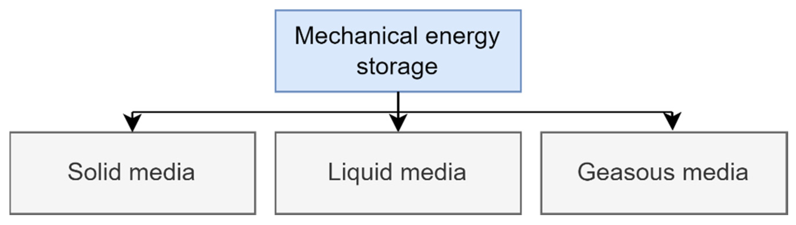
3.5. Mechanical Energy Storage (MES)

Mechanical energy storage systems take advantage of kinetic or gravitational forces to store produced energy. This energy is stored in storage media, and those systems can be divided based on state. The challenging part in the categorization of those systems is that in some cases, storage media changes state in the process and frequently exchanges heat. This is especially true for some types of gaseous and liquid media storage. Those systems are also classified as thermomechanical systems (TMS). The main types of MES systems are presented in the scheme reported in Figure 5.

3.5.1. Solid Media

Flywheel is one of the oldest known energy storage systems, as this principle was first applied in the potter’s wheel [236]. In its simplest form, a flywheel consists of a suspended, rotating mass that stores the energy in the form of kinetic energy of the rotational motion [237]. Moment of inertia the angular velocity of a flywheel can be modified to adjust the storage system to the given application.
A flywheel can act as an electrical energy storage system when coupled with a reversible electric motor. This is a common case, in which surplus electrical energy powers the motor that is connected to the shaft of the flywheel, in turn increasing its angular velocity. The process can be reversed, as the electric motor can act as a generator that gradually turns the flywheel’s kinetic energy into electrical power. Such configuration of a flywheel is commonly found in commercial energy storage systems, one of which was analyzed by Okou et al. [238] in their analysis of small-scale flywheel energy storage technology. In their work, they compared a lead–acid battery and a flywheel as a means of energy storage in rural areas of Uganda. It was presented that over a 10-year period, the application of flywheel storage systems lowered the energy costs by 15%, mainly because of the high maintenance costs of the batteries. The authors also highlighted that the use of an electromechanical flywheel storage system would mitigate the environmental problems associated with lead–acid battery disposal.
Other types of storage systems using solid media are gravity energy storage (GES) and buoyance energy storage (BES). Both of them rely on the relative positioning of a static load in a potential energy field [221]. The energy storage capacity of the system is proportional to the weight and the distance it can travel between its maximum and minimum elevation.
In the category of mechanical energy storage, pumped hydroenergy systems (PHES) and flywheels are overwhelmingly more popular and commercially implemented storage systems than others. However, GES and BES systems are still being developed as they do not lose any of their stored energy over time, in contrast to flywheels, whose energy is drained by friction.
Ruoso et al. [239] created a simulation model of a gravitational potential energy storage system (GES). The modeled system was compact, and it consisted of a 12 m height shaft with a diameter of 4 m. A 5 m tall piston was being moved along the shaft, increasing its potential energy during the charging period and releasing it on demand. This system has a capacity of 11 kWh, an efficiency of about 90%, and a lifetime of 50 years. The developed model presented a promising solution for small-scale storage applications.

3.5.2. Gaseous Media

Compressed air energy storage (CAES) systems use surplus energy to compress air or other gases and inject it into reservoir. It commonly utilizes a depleted underground natural gas reservoir. The compressed air can expand and power an electrical generator during peak periods when the energy is needed most [240]. During the process of gas compression, excess heat is generated, and in the basic CAES system it is dumped into the atmosphere, thus requiring a second injection of heat before the re-expansion of the gas [241]. However, advanced adiabatic CAES stores the excess heat produced during the compression of the gas and reuses it to heat the gas at the expansion.
An interesting investigation regarding CAES has been performed: Cheayb et al. [242] performed a validated simulation of a small-scale CAES with additional trigeneration in their experimental setup. Although the validation provided results very close to the experiment, they also revealed the very low efficiency of a small-scale CAES system. In their setup, the amount of stored energy was equal to 12.1 kWh, and they obtained only 0.5 kWh during discharge. They concluded that further research and mechanical improvements to the system are required to make it a feasible option as a small-scale storage system.

3.5.3. Liquid Media

Liquid air energy storage (LAES) or cryogenic energy storage (CES) works similarly to a CAES system, but the major difference is that the air is liquefied and it is stored in a reservoir. During charging of storage, electricity is used to cool air until it liquefies and then stores the liquid air in a reservoir. When the system is discharged, previously liquefied air is brought back to a gaseous state, heated by the exposure to ambient air or waste heat. Once decompressed, the expanding gas is used to power a turbine and generate electricity. LAES systems are a mature solution that uses off the shelf components that have a lifetime of over 30 years, thus resulting in low technology risk. LAES systems have similar performance characteristics to pumped hydro and can utilize low-grade waste heat. The sizes of such systems extend from around 5 MW to 100+ MW and are very well suited to long duration applications. It is worth mentioning that due to this exchange of heat of the storage media, LAES systems are also categorized as thermomechanical systems (TMS), although the majority of LAES systems currently operational are large-scale installations. Researchers at the Birmingham Centre for Energy Storage [243] designed a micronetwork LAES. The novel part of their approach consisted of the utilization of excess heat produced by LAES, especially when working in the low-pressure range. This way, the overall efficiency of the system was optimized. The resulting hybrid LAES system had a maximum efficiency of around 76% and allowed one to reduce the annual energy consumption by 12.1 MWh compared to the stand-alone LAES. Researchers claim that the new findings suggest that small-scale LAES systems have great potential for applications in local decentralized micro energy networks.

3.5.4. Mechanical Energy Storage: Summary

From the mechanical energy storage systems, pumped hydro is the most used, especially in large-scale applications. However, pumped hydro typically requires natural basins in suitable geological conditions, while LAES systems present similar performance over a broader spectrum of possible locations. Currently, the performance of CAES systems lags behind LAES and pumped hydro and requires further development to become economically competitive.
An additional advantage of potential energy storage systems such as GES, BES, and pumped hydro is that they do not lose any of their charge over time, in contrast to the flywheel, which loses its charge over time relatively quickly.
Solid media storage systems mostly consist of simple mechanical components, which makes them economically appealing; however, as those are moving mechanical components, they require frequent maintenance, which must be considered.

3.6. Storage Technologies: Summary

Table 5 collects multiple researches concerning the topic of energy storage systems in small-scale renewable energy applications. They are focused on small-scale solutions, with the energy input in the range of 10–20 kWh. Each of them presents a different approach to storing energy, and they are briefly discussed below.
The presented examples of small-scale storage systems show that there is no system without its drawbacks, but under certain conditions, they become a beneficial part of a renewable energy system. Incorporation of the energy storage system permits utilization of the surplus energy produced by most renewable energy sources, and this helps to further reduce emissions and decrease the cost of electrical energy. The type of energy storage system is chosen based on multiple factors, with the most significant being storage period, energy conversion, and charge/discharge rate. With a variety of possible solutions, there is a suitable energy storage system for most of the applications.

4. Use of RES Technologies in Polygeneration Hybrid Systems

The described renewable energy and storage technologies are very well suited for use in polygeneration systems. Many studies are being conducted to properly optimize such systems and appropriately adapt the available technologies to consumer needs. Table 6 shows the collected work demonstrating the feasibility of using various RES in small-scale polygeneration systems.
When considering Table 6, the first thing to note is the choice of the location of the systems investigated in the literature. Popular choices of authors are countries with relatively high average annual temperatures, such as India, Spain and Italy. Very few works propose hybrid polygeneration systems in rather cold climates. Countries in northern Europe are a case in point [250]. This fact points directly to problems related to the economic viability of such hybrid system projects. Among all the possibilities, one of the most popular choices for the main source is solar energy. This translates into a relatively low yield of such plants in locations with low values of average annual irradiation. A solar-based installation could very easily become uneconomical compared to conventional solutions under such weather conditions [254]. The single articles whose authors undertook the creation of a polygeneration system in relatively cold climates were mostly based on biomass-burning CHP systems [255].
Photovoltaic technologies are developing rapidly. Recent discoveries include perovskites [256] or other thin-film technologies [257], which at the current stage of research do not have the highest efficiency ratings [258]. The highest efficiencies are enjoyed by multijunction cells [259], but despite this fact, the most common approaches consist of standard, monocrystalline/polycrystalline, photovoltaic modules. As an example, Murthy et al. [244] suggested creating a photovoltaic field to provide electricity and heat in an Indian village. It is worth noting that the system involved the generation of electricity from PV, in parallel with the generation of hydrogen, which was then used to produce electricity and heat using fuel cells when needed. The authors undertook a performance comparison of the proposed system using different energy storage methods. The article is based on the creation of an installation characterized by the minimum amount of energy returned to the country’s power grid, as well as maximum coverage of user demand. The authors pointed out that in this case the best solution is to use lithium ion batteries and hydrogen storage in parallel. The work gives a good indication of how important these technologies are in polygeneration systems. The operation of photovoltaic systems is closely tied to the day and night cycle and seasons, which translates into large energy shortages during periods of low sunshine and large energy surpluses in the opposite situations.
A very popular solution, especially in Mediterranean countries, are hybrid PVT systems. The literature indicates that with the help of such panels, a well-chosen RES-based system can be used to produce electricity, domestic heat and cooling, as well as to heat and desalinate water [245]. The authors proposed using the excess electricity generated to desalinate seawater using the reverse osmosis (RO) phenomenon [260]. Thanks to this procedure, the loss of generated energy is minimized, and thus the economy of the solution increases. RO and other methods of seawater desalination find their use in a large part of modern small polygeneration system concepts [113,114,246,249]. Systems that generate different types of energy while producing fresh water can be a solution to a number of problems of the modern world dealing with fresh water availability. A very popular approach is the adoption of a system based on biomass combustion, where a boiler can be used as the main or additional source of energy. Optimization of a system using mainly solar energy with the presence of an additional biomass boiler was carried out by Calise et al. [246] The paper included a description of the proposed polygeneration system based on CPVT to produce electricity, cooling and utility heat, as well as heat and desalinate water. The authors presented the possibility of optimizing such a system by adjusting the size of the collector field, the number of multieffect distillation (MED) units, the flow rate of chilled water and the heat storage capacity. Economic and exergy analyses were carried out. The first indicated that the solution involving large number of collector systems was highly profitable for the economical point of view, but this fact was contradicted by the conclusions of the second analysis, which revealed a very low utilization rate of the exergy supplied to the system under bigger collector areas. This work indicates that the design of similar systems should be guided by various efficiency indicators of the whole process.
Wind turbines as single energy sources are not very common in polygeneration systems. Due to their unstable operation, even in hybrid systems, the best efficacy of power generation is achieved by systems equipped with energy storage. The authors of [114] showed the possibility of creating a complex polygeneration system incorporating a wooden-chip fueled CHP boiler, a wind turbine, and a photovoltaic system. As for the system reported in [245], it has a seawater desalination unit based on the process of reverse osmosis. The authors also included an additional LPG boiler to support the system in case of energy shortages. However, dynamic simulation indicated that it must only be turned on in a minimal amount of time during the year. The proposed polygeneration system showed high operating efficiency and a variable simple payback period (SPB) between 5.67 and 12.2 years depending on the selected reference scenario. The system is an example of well-chosen components of a hybrid plant, which allowed one to achieve stability of operation and cost-effectiveness of the proposed solution. The importance of thermal and electrical energy storage should be highlighted here, as well as the seawater desalination system, which allowed the use of excess electrical energy, minimizing losses. A very similar solution was described in [247] showing similar use of renewable energy sources (WT, PV, biomass). It is worth noting that the authors carried out system optimizations using different approaches. Two strategies were based on covering the total electricity or heating demand and last one consisted of following modified base load. These optimization approaches made it possible to conduct an economic analysis in each case and identify the best operation strategy of the system.
Apart from systems using hybrid PVT solutions, it should be mentioned that standard solar thermal systems can also be suitable in individual cases. In [248], it is shown that a sufficiently large collector system, working together with a biomass boiler, may be characterized by high cost-effectiveness. It is worth noting that the simulation showed that during the winter period, almost all the heating demand is covered by the boiler, while the summer operation of the system, including the generation of cooling, is ensured practically entirely by solar energy. The authors calculated a SPB of 3.71 years, indicating the system is feasible. However, it should be borne in mind that the proposed system was located in a place with a relatively high average annual insolation. This is an additional fact showing the location-dependent versatility of solar systems. The system proposed in [250] is interesting since it assumes the use of a biomass boiler, PV and WT. in a polygeneration system located in the northern part of Poland. This is a region characterized by relatively low values of average annual solar radiation with respect to southern Europe locations. The author optimized the system by considering four different scenarios for biomass source. Due to the location of the system, the main source of thermal energy and electricity was a biomass boiler coupled with a simple steam Rankine cycle. However, it is worth noting that energy from the wind turbine and the photovoltaic system accounted for 11.1% and 35.1% of the total electricity produced, respectively. This shows that despite the relatively scarce solar energy availability for PV, the region has good prerequisites for wind turbine operation. When designing similar installations, one should keep in mind to maximize the potential of a given location in the world when it comes to energy generation from renewables.
A large part of the systems presented above included some form of energy storage. The most common was a basic hot-water tank, considered as an indispensable element of a standard heating system. Typically, the design and optimization of thermal storages consists only in volume changes, while other forms of improvement, as use of advanced thermal storages (thermochemical, phase-change materials, etc.) are rarely used. Furthermore, individual authors undertake the use of cold storage technology, but this is still not among the popular solutions.
As for electrical energy storage, the use of lithium ion or lead–acid batteries can be seen most often in individual papers. This shows that the authors of the works follow proven and well-known solutions when designing polygeneration systems, and new technologies, which are described extensively in Chapter 3, are often overlooked. The reason consists in the fact that such technologies themselves are not very common and sufficiently researched for the application in energy systems, or it would not be cost-effective to use them on a small scale. However, it is worth noting that more and more installations are observed using hydrogen generation and storage. Fuel cells, once considered a novel approach, are becoming more common, even in commercial applications [261].
Currently in the literature, one can find numerous different proposals for small hybrid polygeneration systems. These are primarily systems based on biomass CHP boilers, as they are characterized by stable operation and are not highly location-dependent. It is worth noting that the use of other technologies, such as PV, PVT or wind turbine installations, carries many limitations related to the geolocation of the entire system. The creation of a hybrid installation is typically characterized by higher efficiency than a single system acquiring energy from one RES. The best locations, where RES-based installations are showing the highest efficiency, are coastal regions characterized by high windiness and relatively high average annual temperature. In this framework, it is worth mentioning that the economy of the systems can be increased with the use of possible means of receiving or storing the excess of generated energy. Recent studies presented in this section indicate that these aspects are intrinsic of modern polygeneration systems.

5. Approaches and Tools in the Design of Integrated Energy Systems

The aim of an integrated energy system is to maximize efficiency and minimize losses [262]. Therefore, sizing the individual components of such a system involves increasing the number of variables and parameters that need to be considered in the design.
Supporting the design process with energy simulations allows one to eliminate the number of errors in the output system and to assess the impact of many variables on its performance. In addition, the occurrence of diverse challenges that have a significant impact on the energy sector, such as combating climate change, economic recession or ensuring energy security [263], results in a significant expansion of aspects to be considered during energy planning. Energy system models are of particular relevance in planning the energy transition and studying its impacts on the energy sector and applications [264].

5.1. Approaches in Modeling of Hybrid Renewable Energy Systems

Energy systems operate in a variable mode by adjusting their operating point to a given energy demand. Renewable energy sources contribute to the computational complexity of such systems due to intermittent energy production and uncertainty in resource availability [265]. The need to understand and predict the performance of the various components of the energy system drives the development of various models. Many approaches to system modeling can be found in the literature, depending on the objective. They are usually classified into three groups—computational, mathematical, and physical—as shown in Figure 6, prepared based on [266], showing the classification for energy models depending on the modeling approach. All these approaches are characterized by varying capabilities in describing the occurring phenomena.
In agent-based models (ABM), the system is modeled as a collection of autonomous decision-making units called agents. The agents’ decisions and evaluations are made based on a set of rules [267]. This approach is most commonly used to forecast electricity prices and also to simulate quantitative trends in customer behavior [268]. However, this is not the only field of application for this approach. Klein et al. [269] presented an agent-based modeling process used in energy systems analysis and energy scenario studies. They present the ability to integrate different algorithms and modeling approaches as a particular advantage.
Knowledge-based models consist of domain-specific knowledge bases and an inference engine that derives new knowledge based on specific rules and a user interface [270]. The approach discussed above was used by Abbey et al. [271] for power planning of a two-stage energy storage system applied to wind systems. Their research showed that the proposed approach can serve as a design procedure for the controller and for the sizing of a short-term storage device.
Neural networks, unlike the knowledge-based models discussed above, do not have explicit rules. They consist of collections of cells that process input and output information. Their training is done by adjusting the connection weights between these nodes [272]. This technique has been used for maximum power point tracking (MPPT) of photovoltaic generators [273], biomass energy prediction [274] or wind energy resource assessment with a forecasting procedure [275]. In a review carried out by Thiaw et al. [276], the MPPT controller design process for photovoltaic generators was presented to improve their efficiency. They also presented a possibility of assessing the available and recoverable wind energy potential of a site, by finding a suitable wind distribution based on a neural model.
With mathematical models, a distinction is usually made between statistical (empirical) and mechanistic (theoretical) methods. The mechanistic approach is based on a mathematical description of a phenomenon or process. The nature of the phenomenon may be chemical, biological or mechanical. It can be used to predict process loads when analyzing components for renewable energy systems, e.g., wind turbine hubs [277].
Modeling and simulation techniques can encompass testing, configuration activities and the development and adaptation processes of the system under study. They also provide a useful tool to support the decision-making process. A simulation is a result of testing a model, which is an abstract representation of the real system [278]. Several simulations can be run with a single model to test alternative solutions. A suitable model should represent a less complex version of the real system. For analysis and evaluation of energy systems, the model should include a description of its properties or performance [279]. Tasking this information will describe the system design processes, its operational patterns and changes in behavior and performance.
Optimization is a certain modeling approach in which there is a calculation of decision variables that minimize or maximize the objective function under constraints [280]. These decision variables are usually the design characteristics of the energy system. In contrast to simulation, optimization mimics the evolution of a situation or system over time [281]. In the literature, we can find many optimization techniques applicable to the dimensioning of hybrid renewable energy systems. These approaches vary according to the optimization objectives. The optimization is required for sizing, combinations, determining operation strategies and scheduling of sources. A number of commercial software have proved useful in sizing and optimizing HRES [282]. Examples of these are described in the following subsections. Figure 7 shows the parameters that make up the corresponding optimization process for hybrid renewable systems. The figure was developed based on [283].
With the iterative method, results are obtained by solving a series of calculation steps starting from a certain starting value. The simulation is carried out until the desired criteria are met [284]. In general, the iterative approach allows the model to be built step by step, and at the same time, any defects in the system under consideration can be caught at early stages [285]. It can also be used for large systems with a large number of components [286]. An example of such is the work written by Geleta et al. [287], where an iterative method was used to select the number of wind turbines and photovoltaic panels for an autonomous system intended to satisfy the desired specific load for a given area. The deterministic method provides accurate weather forecast values for a specific location. On the other hand, the probabilistic method suggests the probability of certain weather events [288]. Both methods work on the basis of weather data implemented from historical data.

5.2. Tools

In addition to the previously presented models used to analyze the behavior of the various components of hybrid systems, simulation and optimization software also plays an important role. Their areas of application can include system design, control strategies, and both multiobjective and economic optimization [289]. This section describes the most commonly used tools in a simulation of a hybrid energy system. Each of them has different possibilities and applications [290,291]. There is software such as TRNSYS and HOMER that can simulate entire complex energy systems, measuring their performance, applicability and economics. With their flexibility, those tools can be used to accomplish vast range of tasks, which are extended with a significant number of additional plugins and incorporated software.
TRNSYS is a highly flexible and graphically based software used to simulate the behavior of transient systems [292]. It has an open and modular structure that allows the incorporation of other previously independent tools. TRNSYS is primarily used to simulate entire energy systems i.e., local communities, off-grid systems or island power systems. It can simulate all thermal and renewable energy generation systems, with the exception of nuclear, wave, tidal, and hydropower. In TRNSYS, the user can define a time step of a simulation in the range from 0.01 s up to typically 1 h with a time span of multiple years.
HOMER-Pro is software designed for microgrid optimization, allowing the calculation of both stand-alone and grid-connected systems. Systems include power sources such as photovoltaics, wind turbines, biomass generators, combustion engines, microturbines and hydro together with storage technologies and loads. Additionally, all economic factors can be included in the process. The simulation can cover a period of one year with a minimum time year of 1 min [293]. It also allows users to create their own dispatch strategy by integrating the software with an algorithm created in MATLAB.
IHOGA/MHOGA are two versions of the Hybrid Optimization by Genetic Algorithms (HOGA) software. IHOGA is dedicated to systems up to 5 MW, while MHOGA covers everything above [294] Both versions can simulate systems including photovoltaic generators, wind and hydroelectric turbines, auxiliary generators, energy storage as well as components of hydrogen (electrolyzer, hydrogen tank and fuel cell). It includes optimized control strategies that can be used for both off-grid systems and grid-connected systems. The software includes multiperiod simulation, multiobjective optimization, sensitivity analysis and probability analysis with time steps of up to 1 min.
The analysis of a hybrid energy system can be additionally supported by tools used to simulate specific parts of the system or physical phenomena that influence the system. When photovoltaics are considered, PVSOL software can be used to perform detailed shading analysis with a 3D visualization including surrounding objects [295]. It can simulate systems from small single-roof scale to large solar parks in combination with appliances, battery systems and electric vehicles.
Where a wind turbine is a part of the hybrid energy system, QBLADE is a tool that can be utilized. It can run highly detailed simulations of any wind turbine design, with advanced physics models more than 20 times as fast as real time [296]. It is primarily used for aero-servo-hydro-elastic design, prototyping, simulation, and certification of wind turbines. Some of its many features are an aerodynamic model of a wind turbine, structural multibody simulation, wind and wave generation, a hydrodynamic model for offshore applications and controller integration.
Further analysis of the complex flow of air or water around turbines can be performed in OpenFOAM. It has an extensive range of features, including fluid flows, chemical reactions, heat transfer or solid mechanics [297]. Additional software that can be used to support physical simulations of the parts of hybrid energy systems is ANSYS. It is a software package that integrates a wide range of tools that can be used to simulate almost any real phenomenon [298].
Lastly, MATLAB software can support the tools mentioned by providing integration of user-defined functions, algorithms, or neural networks [299]. It can generate data describing the behavior of required subcomponents of larger energy systems. Additionally, it is useful in the post-processing of simulation data, providing additional user-defined analysis and visualization.

5.3. Application Examples

For efficient utilization of renewable energy sources, the system’s feasibility needs to be studied before implementation. This approach was applied by Hiendro et al. [300] that presented a technological and economic feasibility analysis of a hybrid system composed of photovoltaic, wind turbine and battery. In order to obtain optimal size determination and cost minimization, HOMER software was used. Researchers found that the most important components in the proposed system are the battery and the wind turbine. HOMER-Pro was also used by Kebedeet et al. [194] in their work to compare the efficiency of a grid-connected photovoltaic system (PVGCS) integrated with a lithium ion battery or a lead–acid battery. Equivalent Circuit Model (ECM) was utilized in order to investigate the performance of batteries. Batteries were included in HOMER-Pro techno-economic analysis considering realistic commercial load profiles. The software allowed the researchers to conclude that in a typical application scenario, lithium ion batteries are recommended as they are more profitable and reduce the overall cost of energy produced by the hybrid system.
In other research, Amutha et al. [193] used the HOMER software to estimate the different types of load requirements in an off-grid hybrid energy system, for the installation of optimal energy sources and battery energy storage. The possible extension of a grid in order to connect to the system was evaluated. Obtained results indicated that the extension of the grid is not economically viable with high initial and maintenance costs.
The use of TRNSYS software can be found in the work of Figaj et al. [114]. The research described a hybrid polygeneration system with wind turbine, photovoltaic field, biomass-fired Rankine cycle, thermal and electrical energy storage, absorption chiller and reverse osmosis water desalination unit. Backup energy in the form of an LPG generator was also included. The system was arranged to satisfy the needs of 10 households on Pantelleria Island, Italy, in terms of electrical energy, heating, cooling and freshwater. The minimum payback period for the investigated installation was 7 years for the reference scenario considering the comparison of the proposed and reference system both connected to the electric grid.
IHOGA was applied in multiple works of Carroquino et al. [301]. One of them is the comparison of lead–acid and lithium ion batteries in the standalone photovoltaic system in Spain. Ten simulations were performed in five different locations, half with a full PV system configuration and the other half with a hybrid system. Optimization processes were carried out in iHOGA software, which simulated the economic and technical operation of the possible solutions of the system. Results regarding the economic comparison show that in only three cases out of ten the optimum was obtained with lithium ion batteries. In the remaining seven cases, lead–acid batteries were better from the point of view of economic performance.
PVSOL was also used in the work of Sharma et al. [302] to design and simulate grid-connected solar PV systems for campus hostels in India. The system designed in PVSOL has a power of 234 kW and covers an area of approximately 1560 m2. Its economic analysis was performed with the same software to determine the feasibility of the system. It was concluded that the expected return on investment is 11 years.
Abdullah et al. [303] used ANSYS for numerical analysis of a hybrid PV thermal air collector. Prior to simulation, a 3D geometric model of the PVT collector was created using ANSYS Design Modeler considering real-world components, which were later used in validating the experiment. A mesh of the mentioned model was created in ANSYS Meshing, which was then imported into the simulation set-up in ANSYS Fluent. The fluid flow and heat transfer characteristics of the PVT collector were determined using computational fluid dynamics (CFD) simulation in mentioned Fluent module. The validation experiment showed that the difference between the simulation and real-world data was not exceeding 2%. By means of simulation, a revised design of the PVT collector was proposed, with the aim to increase its efficiency.
Using Simulink included in MATLAB, El-Hady et al. [304] modeled a photovoltaic and wind turbine hybrid energy system that can supply a load of around 10 kW. The system was tested under changing conditions of wind speed and insolation. Using MATLAB, researchers prepared different load cases, including step changes in load level in order to observe the response of the system.
Moreover, Matlab Simulink was used to simulate systems in the field of electric vehicles. Srujana et al. [305] investigated the components of a battery-electric vehicle framework, and performed a simulation in Simulink to obtain correct sizing. Additionally, a study by Fotouhi et al. [306] presented the development of an estimation model of energy consumption in an EV fleet management system. A usage model of a single EV was created in Simulink and utilized in the analysis of the energy consumption and performance of the entire fleet.
The software listed above is some of the most commonly used in the available literature to investigate hybrid and polygeneration systems. However, there is also other software that can be used to assess the performance of energy systems. There are decision-making programs enabling analysis of energy systems and projects such as RETScreen [307] and EnergyPro [308]. Moreover, EnergyPLAN [309] software is used to simulate the operation of large-scale or national energy systems rather than small-scale ones. Another program, EnergyPlus [310] is also used for building energy simulations that may be coupled with simulation of energy systems. Depending on the type of system under investigation, one can also conduct detailed analyses of individual system components. An example of such a tool is Zemax, which finds its application in optical engineering [311]. Garcia et al. [312] used the software to model parabolic ring array concentrators and calculate the solar flux. Similarly, Tracepro is software for the design and analysis of lighting and optical systems [313]. It was used in [314] to calculate the optical performance of a novel umbrella heliostat.

6. Review Indicators

The approaches and tools described in the previous chapter and used in the modeling and analysis of hybrid and polygeneration systems are intrinsically connected to the calculation of some indicators allowing one to evaluate the performance of chosen design concepts. In fact, the investigation of combinations of technologies adopted in small-scale hybrid and polygeneration systems is performed typically in terms of energy and economy. The energy-related performance indexes are the ones characteristic of technical assessment of energy systems, such as efficiency, energy yield, etc. However, the main aspect that is considered in the investigation of hybrid and polygeneration systems is the economic performance and feasibility. Indeed, such systems may be highly challenging in terms of cost-effectiveness due to their complexity and novelty with respect to conventional technologies. In order to address this challenge, in the scientific literature, there are available several approaches for the investigation of economic performance.
The first approach is to calculate the levelized cost of energy (LCOE). This method is intended to show how much, taking into account investment and maintenance costs, it will cost to generate electricity with the help of the proposed solution. The lower the value of the index, the more profitable the investment. This method is used primarily when comparing different system concepts in the same location with the same energy demand of the consumer. An example is in [118] where a comparison of the performance of a classic PV module and a hybrid PVT was presented. This method was also used by Sigarchian et al. [249], where different strategies were shown when optimizing a polygeneration system, and the LCOE value showed which approach was the best in terms of cost-effectiveness. The calculation of L C O E is presented in Equation (1) [122]:
L C O E = I 0 + t = 1 n C 0 O and M 1 + e + r O and M t / 1 + i t t = 0 n E e l , y / 1 + i t
where I 0 corresponds to the initial investment cost, n is the time period considered in the analysis, t is the time in years, C 0 O a n d M is operation and maintenance costs of considered system, e is yearly inflation rate, r O a n d M is operation and maintenance escalation rate, this value directly shows any increases in maintenance costs during the operation of the system, i is the discount rate, and E e l , y shows the total amount of electricity produced by the system in a year.
As presented above, in order to calculate the LCOE, it is necessary to gather information about the costs of the project, but also to predict the operating costs of the system itself. This indicator relates only to the electricity generated, and thus is very rarely observed for polygeneration installations, where the generation of other types of energy or by-products would have to be evaluated by other calculations.
Another approach is to calculate the net present value (NPV) of an investment, and consequently also the profit index (PI). The higher the PI value, the better the economic efficiency of the investment. This method is more versatile and better suited for verifying the profitability of hybrid polygeneration systems. NPV is the direct difference between the net investment earnings over a given period and the investment cost. The method of calculating P I is presented in Equation (2):
P I = N P V I 0
where I 0 is the initial investment cost. This method is relatively versatile, since a range of cash flows can be taken into account when calculating NPV. This can be shown from [246], where cash flows are presented in the form of savings on CO2 tariffs and energy sales to the country’s electricity grid and operating costs.
However, the calculation of NPV refers to investments, and therefore to possible systems whose operation is characterized by direct profit. For systems in which the sale of produced energy or other products is not the most important, it is possible to use the net present cost (NPC) indicator [315]. The calculation of this indicator is similar to NPV; however, mainly investment costs and the costs that go along with the operation of a given system are taken into account. This can be illustrated by the example in [252]. The authors took into account investment costs, costs of possible component replacements, operations and maintenance costs, as well as fuel costs. In this case, there were sales of electricity. When considering NPC values, the lowest value of this indicator will be characterized by the most cost-effective solutions.
One of the most popular methods of assessing the economic viability of an investment is the calculation of simple payback (SPB) period. Many authors of works on RES-based hybrid polygeneration systems use this method for economic analysis [113,114,250,253]. This indicator shows after how many years the total return on investment costs of a given system will be observed, which directly allows comparing different system concepts. The calculation of S P B is shown in Equation (3):
S P B = I 0 I n
where I 0 is the initial investment cost, and I n describes the net annual revenue. When using this method, it should be kept in mind that its simplicity can directly affect the accuracy of the results. During the calculation, the evolution of the value of money over time, and therefore the possible variation in revenue over the year, is usually not taken into account. Despite these limitations, the method is well suited for comparing the economic viability of different solutions, primarily different variants of systems in the same location.
In addition to economic approaches, it is also worth mentioning other methods of comparing the hybrid systems. One of them can be the levelized cover ratio (LCR), which directly shows how much of the user’s energy demand is covered by the proposed system. This method is used to optimize the system, but its highest indications do not necessarily coincide with the best economical solution. The LCR calculation must involve an additional economic evaluation of each of the compared solutions [251]. To calculate the L C R , it is possible to use Equation (4):
L C R = E u s e r E e x E u s e r
where E u s e r is the energy demand of the system user and E e x is the value of energy that must be supplied from an external source, which can be an additional generator or the country’s power grid. For polygeneration systems in particular, polygeneration indicators are a popular method for evaluating a given concept. They allow us to illustrate what positive aspects come from polygeneration in relation to separate generation. This method was used by Picallo-Perez et al. [251], calculating the percentage of energy savings (PES). This parameter can also be referred to the calculation of exergy efficiency. The authors presented a thorough description of the entire calculation of these parameters in their work.

7. Conclusions

Hybrid and polygeneration renewable energy systems have received particular attention in the recent period from researchers, technicians, policymakers and stakeholders, making them a possible means of achieving the goals of present-day energy systems and distributed generation. In this context, the adoption of hybrid and polygeneration schemes is possible on different scales, from big plants to small-scale applications at the level of a single household. The adoption of renewable energy systems based on the use of multiple energy sources may lead to significant advantages, such as the reduction of negative effects of energy generation fluctuation, improved energy independence of the user, and significant reduction of energy bills. These advantages can be even more if the adopted energy system is not only limited to a monogeneration regime, but instead allows one to produce more forms of energy along with other useful substances or final products. Investigations of such systems are relatively common in the scientific literature for medium or large systems, while for small-scale systems, as pointed put by this review, there is significant potential for improvement of technical and scientific knowledge regarding the combination of energy sources, adoption of different technologies and applications.
The development the investigations on hybrid and polygeneration systems powered by renewables is related to several aspects of such systems, as the ones involving the available technologies for energy generation and storage, use of renewable technologies and the configurations of systems, and the methodology and tools adopted in the assessment of energy and economic performance. In the present review, the authors focused on the latter standpoints to outline the state of the art regarding the research of hybrid polygeneration renewable energy systems. The main outcomes from this review are summarized as follows.
-
From the point of view of energy generation technologies, the availability of commercially ready devices is vast and mature, since it ranges between solar collector and photovoltaic panels, wind and water turbines, biomass boilers and heat pumps. Typically, investigations on a small scale rely on proven universal technologies since the goal is to assess the performance of a specific system, rather than the investigation of the performance of a novel and advanced component. As regards systems based on only one technology, wind turbines and photovoltaic panels are the most common solution, while systems based exclusively on biomass are scarcely investigated.
-
All storage technologies in small-scale storage systems have their drawbacks, but under appropriate conditions, they are an essential part of a renewable energy system. Despite a wide availability of thermal and electrical energy storage technologies, the systems are mainly based on common solutions, such as lead–acid or lithium ion batteries or liquid storage tanks. Moreover, hydrogen systems are also a possibility for storage of electrical energy in several applications available in literature. In general, the type of energy storage system is chosen on the basis of several factors, such as level of autonomy, efficiency, and energy charge and discharge rate. With a variety of possible solutions, there is a suitable energy storage system for most of the applications.
-
The systems investigated in the literature mainly focus on the combination of solar, wind and biomass, for which the investigations are conducted to properly optimize the configuration and appropriately adapt the available technologies to user needs. Due to the massive adoption of solar energy in systems, locations with relatively high average annual temperatures and solar availability are considered, while only few works propose hybrid polygeneration systems in cold climates. There are also examples based on biomass boilers, since they are characterized by stable operation and are not affected by the weather conditions.
-
The tools and methodologies for investigation of the performance of hybrid polygeneration systems based on renewables involved in almost all the cases the adoption of an analytical/numerical approach. This is obviously connected to the relatively high cost of development of pilot and experimental setups for small-scale applications. Therefore, the investigations are performed by means of tools such as TRNSYS and HOMER in order to select the individual components and design the configuration of whole systems. In this process, a significant number of variables and parameters are considered, in the form of weather conditions, technical specification of devices, control strategies and economic scenarios adopted for the analysis. In general, the main goal used in such tools is to assess the operational characteristics of the system, perform energy and economic analyses, and optimize the system by means of selected criteria.
In the context of the present review, it possible to identify some pathways in the investigation of hybrid polygeneration renewable energy systems in small-scale applications, as listed below:
-
investigation of pairing of renewable energy sources other than the conventional solar–wind one, and the integration of three or more renewable energy sources, as for solar–wind–biomass systems;
-
analysis of the possibilities of integration of advanced energy storages, as phase-change materials, methane (methanation), compressed air storage, and thermochemical heat storage;
-
investigation of suitable applications/users for hybrid and polygeneration systems that are different from the ones typically selected as case studies, such as villages and small communities.

Author Contributions

Conceptualization, M.Ż. and R.F.; methodology, M.Ż. and R.F.; formal analysis, M.Ż. and R.F.; investigation, M.H. and A.P.; data curation, M.H., A.P. and M.Ż.; writing—original draft preparation, M.H., A.P., M.Ż. and R.F.; writing—review and editing, M.Ż. and R.F.; visualization, M.H. and A.P.; supervision, R.F. All authors have read and agreed to the published version of the manuscript.

Funding

Part of this research was funded by the Polish Ministry of Higher Education on the basis of decision 0086/DIA/2019/48.

Data Availability Statement

Not applicable.

Acknowledgments

This work was carried out under Subvention and Subvention for Young Scientists, Faculty of Energy and Fuels, AGH University of Science and Technology, Krakow, Poland. The authors acknowledge the use of the infrastructure of the Center of Energy, AGH UST in Krakow. The research was supported by the Foundation for Polish Science (FNP).

Conflicts of Interest

The authors declare no conflict of interest.

References

  1. Net Zero by 2050—Analysis—IEA. Available online: https://www.iea.org/reports/net-zero-by-2050 (accessed on 28 October 2022).
  2. Kałuża, T.; Hämmerling, M.; Zawadzki, P.; Czekała, W.; Kasperek, R.; Sojka, M.; Mokwa, M.; Ptak, M.; Szkudlarek, A.; Czechlowski, M.; et al. The Hydropower Sector in Poland: Historical Development and Current Status. Renew. Sustain. Energy Rev. 2022, 158, 112150. [Google Scholar] [CrossRef]
  3. Kaldellis, J.K.; Zafirakis, D. The Wind Energy (r)Evolution: A Short Review of a Long History. Renew. Energy 2011, 36, 1887–1901. [Google Scholar] [CrossRef]
  4. Executive Summary—Unlocking the Potential of Distributed Energy Resources—Analysis—IEA. Available online: https://www.iea.org/reports/unlocking-the-potential-of-distributed-energy-resources/executive-summary (accessed on 28 October 2022).
  5. Norouztabar, R.; Ajarostaghi, S.S.M.; Mousavi, S.S.; Nejat, P.; Koloor, S.S.R.; Eldessouki, M. On the Performance of a Modified Triple Stack Blade Savonius Wind Turbine as a Function of Geometrical Parameters. Sustainability 2022, 14, 9816. [Google Scholar] [CrossRef]
  6. Yang, J.; Luo, X.; Zhou, Y.; Li, Y.; Qiu, Q.; Xie, T. Recent Advances in Inverted Perovskite Solar Cells: Designing and Fabrication. Int. J. Mol. Sci. 2022, 23, 11792. [Google Scholar] [CrossRef]
  7. Feinauer, M.; Uhlmann, N.; Ziebert, C.; Blank, T. Simulation, Set-Up, and Thermal Characterization of a Water-Cooled Li-Ion Battery System. Batteries 2022, 8, 177. [Google Scholar] [CrossRef]
  8. Minai, F.; Márquez, G.; Jiménez, A.; Gonzalez Lamar, D.; Faiz Minai, A.; Ahmad Khan, A.; Kumar Pachauri, R.; Malik, H.; Pedro García Márquez, F.; Arcos Jiménez, A. Performance Evaluation of Solar PV-Based Z-Source Cascaded Multilevel Inverter with Optimized Switching Scheme. Electronics 2022, 11, 3706. [Google Scholar] [CrossRef]
  9. Wincukiewicz, A.; Wierzyńska, E.; Bohdan, A.; Tokarczyk, M.; Korona, K.P.; Skompska, M.; Kamińska, M. Enhanced Performance of Camphorsulfonic Acid-Doped Perovskite Solar Cells. Molecules 2022, 27, 7850. [Google Scholar] [CrossRef]
  10. Ang, T.Z.; Salem, M.; Kamarol, M.; Das, H.S.; Nazari, M.A.; Prabaharan, N. A Comprehensive Study of Renewable Energy Sources: Classifications, Challenges and Suggestions. Energy Strategy Rev. 2022, 43, 100939. [Google Scholar] [CrossRef]
  11. Benavides, D.; Arévalo, P.; Tostado-Véliz, M.; Vera, D.; Escamez, A.; Aguado, J.A.; Jurado, F. An Experimental Study of Power Smoothing Methods to Reduce Renewable Sources Fluctuations Using Supercapacitors and Lithium-Ion Batteries. Batteries 2022, 8, 228. [Google Scholar] [CrossRef]
  12. Pasetti, M.; Amini, S.; Bahramara, S.; Golpîra, H.; Francois, B.; Soares, J. Techno-Economic Analysis of Renewable-Energy-Based Micro-Grids Considering Incentive Policies. Energies 2022, 15, 8285. [Google Scholar]
  13. Bekun, F.V.; Kambule, N.; Adepoju, O.; Karahüseyin, T.; Abbaso, S. Performance Loss Rates of a 1 MWp PV Plant with Various Tilt Angle, Orientation and Installed Environment in the Capital of Cyprus. Sustainability 2022, 14, 9084. [Google Scholar]
  14. Tao, S.; Li, C.; Zhang, L.; Tang, Y. Operational Risk Assessment of Grid-Connected PV System Considering Weather Variability and Component Availability. Energy Procedia 2018, 145, 252–258. [Google Scholar] [CrossRef]
  15. Oyekale, J.; Petrollese, M.; Cocco, D.; Cau, G. Annualized Exergoenvironmental Comparison of Solar-Only and Hybrid Solar-Biomass Heat Interactions with an Organic Rankine Cycle Power Plant. Energy Convers. Manag. X 2022, 15, 100229. [Google Scholar] [CrossRef]
  16. Son, I.W.; Jeong, Y.; Son, S.; Park, J.H.; Lee, J.I. Techno-Economic Evaluation of Solar-Nuclear Hybrid System for Isolated Grid. Appl. Energy 2022, 306, 118046. [Google Scholar] [CrossRef]
  17. Kang, D.; Jung, T.Y. Renewable Energy Options for a Rural Village in North Korea. Sustainability 2020, 12, 2452. [Google Scholar] [CrossRef] [Green Version]
  18. Silva, F.M.Q.; el Kattel, M.B.; Pires, I.A.; Maia, T.A.C. Development of a Supervisory System Using Open-Source for a Power Micro-Grid Composed of a Photovoltaic (PV) Plant Connected to a Battery Energy Storage System and Loads. Energies 2022, 15, 8324. [Google Scholar] [CrossRef]
  19. Dzhonova-Atanasova, D.; Georgiev, A.; Nakov, S.; Panyovska, S.; Petrova, T.; Maiti, S. Compact Thermal Storage with Phase Change Material for Low-Temperature Waste Heat Recovery—Advances and Perspectives. Energies 2022, 15, 8269. [Google Scholar] [CrossRef]
  20. Islam, M.R.; Akter, H.; Howlader, H.O.R.; Senjyu, T. Optimal Sizing and Techno-Economic Analysis of Grid-Independent Hybrid Energy System for Sustained Rural Electrification in Developing Countries: A Case Study in Bangladesh. Energies 2022, 15, 6381. [Google Scholar] [CrossRef]
  21. Nazir, S.; Farah, S.; Paend Bakht, M.; Salam, Z.; Gul, M.; Anjum, W.; Kamaruddin, M.A.; Khan, N.; Lawan Bukar, A. The Potential Role of Hybrid Renewable Energy System for Grid Intermittency Problem: A Techno-Economic Optimisation and Comparative Analysis. Sustainability 2022, 14, 14045. [Google Scholar]
  22. Liang, T.; Webley, P.A.; Chen, Y.C.; She, X.; Li, Y.; Ding, Y. The Optimal Design and Operation of a Hybrid Renewable Micro-Grid with the Decoupled Liquid Air Energy Storage. J. Clean. Prod. 2022, 334, 130189. [Google Scholar] [CrossRef]
  23. Deltenre, Q.; de Troyer, T.; Runacres, M.C. Performance Assessment of Hybrid PV-Wind Systems on High-Rise Rooftops in the Brussels-Capital Region. Energy Build. 2020, 224, 110137. [Google Scholar] [CrossRef]
  24. Harrison-Atlas, D.; Murphy, C.; Schleifer, A.; Grue, N. Temporal Complementarity and Value of Wind-PV Hybrid Systems across the United States. Renew. Energy 2022, 201, 111–123. [Google Scholar] [CrossRef]
  25. Tercan, S.M.; Demirci, A.; Gokalp, E.; Cali, U. Maximizing Self-Consumption Rates and Power Quality towards Two-Stage Evaluation for Solar Energy and Shared Energy Storage Empowered Microgrids. J. Energy Storage 2022, 51, 104561. [Google Scholar] [CrossRef]
  26. Orioli, A.; di Gangi, A. Five-Years-Long Effects of the Italian Policies for Photovoltaics on the Energy Demand Coverage of Grid-Connected PV Systems Installed in Urban Contexts. Energy 2016, 113, 444–460. [Google Scholar] [CrossRef]
  27. Knowles, J. Overview of Small and Micro Combined Heat and Power (CHP) Systems. In Small and Micro Combined Heat and Power (CHP) Systems; Woodhead Publishing: Soston, UK, 2011; pp. 3–16. [Google Scholar]
  28. Im, Y. Assessment of the Impact of Renewable Energy Expansion on the Technological Competitiveness of the Cogeneration Model. Energies 2022, 15, 6844. [Google Scholar] [CrossRef]
  29. Bagherian, M.A.; Mehranzamir, K. A Comprehensive Review on Renewable Energy Integration for Combined Heat and Power Production. Energy Convers. Manag. 2020, 224, 113454. [Google Scholar] [CrossRef]
  30. Tahir, M.F.; Haoyong, C.; Guangze, H. Evaluating Individual Heating Alternatives in Integrated Energy System by Employing Energy and Exergy Analysis. Energy 2022, 249, 123753. [Google Scholar] [CrossRef]
  31. Pieper, H.; Kirs, T.; Krupenski, I.; Ledvanov, A.; Lepiksaar, K.; Volkova, A. Efficient Use of Heat from CHP Distributed by District Heating System in District Cooling Networks. Energy Rep. 2021, 7, 47–54. [Google Scholar] [CrossRef]
  32. Maidment, G.G.; Prosser, G. The Use of CHP and Absorption Cooling in Cold Storage. Appl. Therm. Eng. 2000, 20, 1059–1073. [Google Scholar] [CrossRef]
  33. Gimelli, A.; Muccillo, M. Development of a 1 KW Micro-Polygeneration System Fueled by Natural Gas for Single-Family Users. Energies 2021, 14, 8372. [Google Scholar] [CrossRef]
  34. Ramadhani, F.; Hussain, M.A.; Mokhlis, H.; Erixno, O. Solid Oxide Fuel Cell-Based Polygeneration Systems in Residential Applications: A Review of Technology, Energy Planning and Guidelines for Optimizing the Design. Processes 2022, 10, 2126. [Google Scholar] [CrossRef]
  35. Rong, A.; Lahdelma, R. Role of Polygeneration in Sustainable Energy System Development Challenges and Opportunities from Optimization Viewpoints. Renew. Sustain. Energy Rev. 2016, 53, 363–372. [Google Scholar] [CrossRef] [Green Version]
  36. Renewables—Global Energy Review 2021—Analysis; International Energy Agency (IEA): Paris, France, 2021.
  37. Żołądek, M.; Filipowicz, M.; Sornek, K.; Figaj, R.D. Energy Performance of the Photovoltaic System in Urban Area—Case Study. IOP Conf. Ser. Earth Environ. Sci. 2019, 214, 012123. [Google Scholar] [CrossRef]
  38. Aslam, A.; Ahmed, N.; Qureshi, S.A.; Assadi, M.; Ahmed, N. Advances in Solar PV Systems; A Comprehensive Review of PV Performance, Influencing Factors, and Mitigation Techniques. Energies 2022, 15, 7595. [Google Scholar] [CrossRef]
  39. Praveenkumar, S.; Gulakhmadov, A.; Agyekum, E.B.; Alwan, N.T.; Velkin, V.I.; Sharipov, P.; Safaraliev, M.; Chen, X. Experimental Study on Performance Enhancement of a Photovoltaic Module Incorporated with CPU Heat Pipe—A 5E Analysis. Sensors 2022, 22, 6367. [Google Scholar] [CrossRef]
  40. Sornek, K.; Goryl, W.; Figaj, R.; Dąbrowska, G.; Brezdeń, J. Development and Tests of the Water Cooling System Dedicated to Photovoltaic Panels. Energies 2022, 15, 5884. [Google Scholar] [CrossRef]
  41. Inside Asia’s Floating Solar Panels Boom. Available online: https://energytracker.asia/inside-asias-floating-solar-panels-boom/ (accessed on 28 October 2022).
  42. Cazzaniga, R.; Cicu, M.; Rosa-Clot, M.; Rosa-Clot, P.; Tina, G.M.; Ventura, C. Floating Photovoltaic Plants: Performance Analysis and Design Solutions. Renew. Sustain. Energy Rev. 2018, 81, 1730–1741. [Google Scholar] [CrossRef]
  43. Nisar, H.; Janjua, A.K.; Hafeez, H.; Shakir, S.; Shahzad, N.; Waqas, A. Thermal and Electrical Performance of Solar Floating PV System Compared to On-Ground PV System-an Experimental Investigation. Sol. Energy 2022, 241, 231–247. [Google Scholar] [CrossRef]
  44. Al-Ezzi, A.S.; Ansari, M.N.M. Photovoltaic Solar Cells: A Review. Appl. Syst. Innov. 2022, 5, 67. [Google Scholar] [CrossRef]
  45. Powell, K.M.; Rashid, K.; Ellingwood, K.; Tuttle, J.; Iverson, B.D. Hybrid Concentrated Solar Thermal Power Systems: A Review. Renew. Sustain. Energy Rev. 2017, 80, 215–237. [Google Scholar] [CrossRef] [Green Version]
  46. El-Mahallawi, I.; Elshazly, E.; Ramadan, M.; Nasser, R.; Yasser, M.; El-Badry, S.; Elthakaby, M.; Oladinrin, O.T.; Rana, M.Q. Solar PV Panels-Self-Cleaning Coating Material for Egyptian Climatic Conditions. Sustainability 2022, 14, 11001. [Google Scholar] [CrossRef]
  47. Ahmed, M.; Harbi, I.; Kennel, R.; Rodríguez, J.; Abdelrahem, M. Evaluation of the Main Control Strategies for Grid-Connected PV Systems. Sustainability 2022, 14, 11142. [Google Scholar] [CrossRef]
  48. Vankadara, S.K.; Chatterjee, S.; Balachandran, P.K.; Mihet-Popa, L. Marine Predator Algorithm (MPA)-Based MPPT Technique for Solar PV Systems under Partial Shading Conditions. Energies 2022, 15, 6172. [Google Scholar] [CrossRef]
  49. Giwa, A.; Yusuf, A.; Dindi, A.; Balogun, H.A. Polygeneration in Desalination by Photovoltaic Thermal Systems: A Comprehensive Review. Renew. Sustain. Energy Rev. 2020, 130, 109946. [Google Scholar] [CrossRef]
  50. Yao, W.; Kong, X.; Han, X.; Wang, Y.; Cao, J.; Gao, W. Research on the Efficiency Evaluation of Heat Pipe PV/T Systems and Its Applicability in Different Regions of China. Energy Convers. Manag. 2022, 269, 116136. [Google Scholar] [CrossRef]
  51. Figaj, R.; Żołądek, M.; Gory, W. Dynamic Simulation and Energy Economic Analysis of a Household Hybrid Ground-Solar-Wind System Using TRNSYS Software. Energies 2020, 13, 3523. [Google Scholar] [CrossRef]
  52. Ahmed, S.F.; Khalid, M.; Vaka, M.; Walvekar, R.; Numan, A.; Rasheed, A.K.; Mubarak, N.M. Recent Progress in Solar Water Heaters and Solar Collectors: A Comprehensive Review. Therm. Sci. Eng. Prog. 2021, 25, 100981. [Google Scholar] [CrossRef]
  53. Salek, F.; Eshghi, H.; Zamen, M.; Ahmadi, M.H. Energy and Exergy Analysis of an Atmospheric Water Generator Integrated with the Compound Parabolic Collector with Storage Tank in Various Climates. Energy Rep. 2022, 8, 2401–2412. [Google Scholar] [CrossRef]
  54. Gao, X.; Wei, S.; Xia, C.; Li, Y. Flexible Operation of Concentrating Solar Power Plant with Thermal Energy Storage Based on a Coordinated Control Strategy. Energies 2022, 15, 4929. [Google Scholar] [CrossRef]
  55. Figaj, R.; Żoładek, M. Operation and Performance Assessment of a Hybrid Solar Heating and Cooling System for Different Configurations and Climatic Conditions. Energies 2021, 14, 1142. [Google Scholar] [CrossRef]
  56. Figaj, R.; Żołądek, M. Experimental and Numerical Analysis of Hybrid Solar Heating and Cooling System for a Residential User. Renew. Energy 2021, 172, 955–967. [Google Scholar] [CrossRef]
  57. Zhang, K.; Su, Y.; Wang, H.; Wang, Q.; Wang, K.; Niu, Y.; Song, J. Highly Concentrated Solar Flux of Large Fresnel Lens Using CCD Camera-Based Method. Sustainability 2022, 14, 11062. [Google Scholar] [CrossRef]
  58. Adnan, M.; Zaman, M.; Ullah, A.; Gungor, A.; Rizwan, M.; Raza Naqvi, S. Thermo-Economic Analysis of Integrated Gasification Combined Cycle Co-Generation System Hybridized with Concentrated Solar Power Tower. Renew. Energy 2022, 198, 654–666. [Google Scholar] [CrossRef]
  59. Jamshed, W.; Şirin, C.; Selimefendigil, F.; Shamshuddin, M.D.; Altowairqi, Y.; Eid, M.R. Thermal Characterization of Coolant Maxwell Type Nanofluid Flowing in Parabolic Trough Solar Collector (PTSC) Used Inside Solar Powered Ship Application. Coatings 2021, 11, 1552. [Google Scholar] [CrossRef]
  60. Wohld, J.; Beck, J.; Inman, K.; Palmer, M.; Cummings, M.; Fulmer, R.; Vafaei, S. Hybrid Nanofluid Thermal Conductivity and Optimization: Original Approach and Background. Nanomaterials 2022, 12, 2847. [Google Scholar] [CrossRef]
  61. George, A. Lane Solar Heat Storage: Volume I: Latent Heat Material, 1st ed.; CRC Press: Boca Raton, FL, USA, 2017. [Google Scholar]
  62. Mouaky, A.; Rachek, A. Thermodynamic and Thermo-Economic Assessment of a Hybrid Solar/Biomass Polygeneration System under the Semi-Arid Climate Conditions. Renew. Energy 2020, 156, 14–30. [Google Scholar] [CrossRef]
  63. Kasaeian, A.; Bellos, E.; Shamaeizadeh, A.; Tzivanidis, C. Solar-Driven Polygeneration Systems: Recent Progress and Outlook. Appl. Energy 2020, 264, 114764. [Google Scholar] [CrossRef]
  64. Bošnjaković, M.; Katinić, M.; Santa, R.; Marić, D. Wind Turbine Technology Trends. Appl. Sci. 2022, 12, 8653. [Google Scholar] [CrossRef]
  65. Das Karmakar, S.; Chattopadhyay, H. A Review of Augmentation Methods to Enhance the Performance of Vertical Axis Wind Turbine. Sustain. Energy Technol. Assess. 2022, 53, 102469. [Google Scholar] [CrossRef]
  66. Kim, S.; Cheong, C. Development of Low-Noise Drag-Type Vertical Wind Turbines. Renew. Energy 2015, 79, 199–208. [Google Scholar] [CrossRef]
  67. Müller, G.; Chavushoglu, M.; Kerri, M.; Tsuzaki, T. A Resistance Type Vertical Axis Wind Turbine for Building Integration. Renew. Energy 2017, 111, 803–814. [Google Scholar] [CrossRef] [Green Version]
  68. Dabachi, M.A.; Rouway, M.; Rahmouni, A.; Bouksour, O.; Sbai, S.J.; Laaouidi, H.; Tarfaoui, M.; Aamir, A.; Lagdani, O. Numerical Investigation of the Structural Behavior of an Innovative Offshore Floating Darrieus-Type Wind Turbines with Three-Stage Rotors. J. Compos. Sci. 2022, 6, 167. [Google Scholar] [CrossRef]
  69. Aihara, A.; Mendoza, V.; Goude, A.; Bernhoff, H. Comparison of Three-Dimensional Numerical Methods for Modeling of Strut Effect on the Performance of a Vertical Axis Wind Turbine. Energies 2022, 15, 2361. [Google Scholar] [CrossRef]
  70. Riegler, H. HAWT versus VAWT: Small VAWTs Find a Clear Niche. Refocus 2003, 4, 44–46. [Google Scholar]
  71. Zhu, C.; Wang, T.; Zhong, W. Combined Effect of Rotational Augmentation and Dynamic Stall on a Horizontal Axis Wind Turbine. Energies 2019, 12, 1434. [Google Scholar] [CrossRef] [Green Version]
  72. Gil-García, I.C.; García-Cascales, M.S.; Molina-García, A. Urban Wind: An Alternative for Sustainable Cities. Energies 2022, 15, 4759. [Google Scholar] [CrossRef]
  73. Giorgi, D.; Li, R.; Wang, Y.; Lin, H.; Du, H.; Wang, C.; Chen, X.; Huang, M. A Mesoscale CFD Simulation Study of Basic Wind Pressure in Complex Terrain—A Case Study of Taizhou City. Appl. Sci. 2022, 12, 10481. [Google Scholar]
  74. Noronha, N.P.; Krishna, M. Aerodynamic Performance Comparison of Airfoils Suggested for Small Horizontal Axis Wind Turbines. Mater. Today Proc. 2021, 46, 2450–2455. [Google Scholar] [CrossRef]
  75. Zhang, J.H.; Lien, F.S.; Yee, E. Investigations of Vertical-Axis Wind-Turbine Group Synergy Using an Actuator Line Model. Energies 2022, 15, 6211. [Google Scholar] [CrossRef]
  76. Adeyeye, K.A.; Ijumba, N.; Colton, J. The Effect of the Number of Blades on the Efficiency of A Wind Turbine. IOP Conf. Ser. Earth Environ. Sci. 2021, 801, 12020. [Google Scholar] [CrossRef]
  77. Ranjbar, M.H.; Rafiei, B.; Nasrazadani, S.A.; Gharali, K.; Soltani, M.; Al-Haq, A.; Nathwani, J. Power Enhancement of a Vertical Axis Wind Turbine Equipped with an Improved Duct. Energies 2021, 14, 5780. [Google Scholar] [CrossRef]
  78. Basbas, H.; Liu, Y.C.; Laghrouche, S.; Hilairet, M.; Plestan, F. Review on Floating Offshore Wind Turbine Models for Nonlinear Control Design. Energies 2022, 15, 5477. [Google Scholar] [CrossRef]
  79. Smoleń, J.; Olesik, P.; Jała, J.; Adamcio, A.; Kurtyka, K.; Godzierz, M.; Kozera, R.; Kozioł, M.; Boczkowska, A. The Use of Carbon Fibers Recovered by Pyrolysis from End-of-Life Wind Turbine Blades in Epoxy-Based Composite Panels. Polymers 2022, 14, 2925. [Google Scholar] [CrossRef] [PubMed]
  80. Hamidifar, H.; Akbari, F.; Rowiński, P.M. Assessment of Environmental Water Requirement Allocation in Anthropogenic Rivers with a Hydropower Dam Using Hydrologically Based Methods—Case Study. Water 2022, 14, 893. [Google Scholar] [CrossRef]
  81. Esquivel-Sancho, L.M.; Muñoz-Arias, M.; Phillips-Brenes, H.; Pereira-Arroyo, R. A Reversible Hydropump–Turbine System. Appl. Sci. 2022, 12, 9086. [Google Scholar] [CrossRef]
  82. Joy, J.; Raisee, M.; Cervantes, M.J. Hydraulic Performance of a Francis Turbine with a Variable Draft Tube Guide Vane System to Mitigate Pressure Pulsations. Energies 2022, 15, 6542. [Google Scholar] [CrossRef]
  83. Qasim, M.A.; Velkin, V.I.; Shcheklein, S.E.; Hanfesh, A.O.; Farge, T.Z.; Essa, F.A. A Numerical Analysis of Fluid Flow and Torque for Hydropower Pelton Turbine Performance Using Computational Fluid Dynamics. Inventions 2022, 7, 22. [Google Scholar] [CrossRef]
  84. Okot, D.K. Review of Small Hydropower Technology. Renew. Sustain. Energy Rev. 2013, 26, 515–520. [Google Scholar] [CrossRef]
  85. Yoosefdoost, A.; Lubitz, W.D.; Dario, O.; Mejia, L. Design Guideline for Hydropower Plants Using One or Multiple Archimedes Screws. Processes 2021, 9, 2128. [Google Scholar] [CrossRef]
  86. Sinagra, M.; Picone, C.; Picone, P.; Aricò, C.; Tucciarelli, T.; Ramos, H.M. Low-Head Hydropower for Energy Recovery in Wastewater Systems. Water 2022, 14, 1649. [Google Scholar] [CrossRef]
  87. Rotilio, M.; Marchionni, C.; de Berardinis, P. The Small-Scale Hydropower Plants in Sites of Environmental Value: An Italian Case Study. Sustainability 2017, 9, 2211. [Google Scholar] [CrossRef] [Green Version]
  88. Bravo-Córdoba, F.J.; Torrens, J.; Fuentes-Pérez, J.F.; García-Vega, A.; Sanz-Ronda, F.J. Fishway Attraction Efficiency during Upstream and Down-Stream Migration: Field Tests in a Small Hydropower Plant with Run-of-the-River Configuration. Biol. Life Sci. Forum 2022, 13, 40. [Google Scholar]
  89. Sornek, K.; Żołądek, M.; Goryl, W.; Figaj, R. The Operation of a Micro-Scale Cogeneration System Prototype—A Comprehensive Experimental and Numerical Analysis. Fuel 2021, 295, 120563. [Google Scholar] [CrossRef]
  90. Żołądek, M.; Kafetzis, A.; Figaj, R.; Panopoulos, K. Energy-Economic Assessment of Islanded Microgrid with Wind Turbine, Photovoltaic Field, Wood Gasifier, Battery, and Hydrogen Energy Storage. Sustainability 2022, 14, 12470. [Google Scholar] [CrossRef]
  91. Zhang, W.; Wei, C.; Liu, X.; Zhang, Z. Frost Resistance and Mechanism of Circulating Fluidized Bed Fly Ash-Blast Furnace Slag-Red Mud-Clinker Based Cementitious Materials. Materials 2022, 15, 6311. [Google Scholar] [CrossRef] [PubMed]
  92. Vershinina, K.; Nyashina, G.; Strizhak, P. Combustion, Pyrolysis, and Gasification of Waste-Derived Fuel Slurries, Low-Grade Liquids, and High-Moisture Waste: Review. Appl. Sci. 2022, 12, 1039. [Google Scholar] [CrossRef]
  93. Pedretti, F.; European Hophornbeam, E.; Ilari, A.; Fabrizi, S.; Foppa Pedretti, E. European Hophornbeam Biomass for Energy Application: Influence of Different Production Processes and Heating Devices on Environmental Sustainability. Resources 2022, 11, 11. [Google Scholar]
  94. Żołądek, M.; Figaj, R.; Sornek, K. Energy Analysis of a Micro-Scale Biomass Cogeneration System. Energy Convers. Manag. 2021, 236, 114079. [Google Scholar] [CrossRef]
  95. Wagle, A.; Angove, M.J.; Mahara, A.; Wagle, A.; Mainali, B.; Martins, M.; Goldbeck, R.; Paudel, S.R. Multi-Stage Pre-Treatment of Lignocellulosic Biomass for Multi-Product Biorefinery: A Review. Sustain. Energy Technol. Assess. 2022, 49, 101702. [Google Scholar] [CrossRef]
  96. Bagherian, M.A.; Mehranzamir, K.; Rezania, S.; Abdul-Malek, Z.; Pour, A.B.; Alizadeh, S.M. Analyzing Utilization of Biomass in Combined Heat and Power and Combined Cooling, Heating, and Power Systems. Processes 2021, 9, 1002. [Google Scholar] [CrossRef]
  97. Wołowicz, M.; Kolasiński, P.; Badyda, K. Modern Small and Microcogeneration Systems—A Review. Energies 2021, 14, 785. [Google Scholar] [CrossRef]
  98. Heat Pumps—Analysis—IEA. Available online: https://www.iea.org/reports/heat-pumps (accessed on 18 November 2022).
  99. Xiao, S.; Nefodov, D.; McLinden, M.O.; Richter, M.; Urbaneck, T. Working Fluid Selection for Heat Pumps in Solar District Heating Systems. Sol. Energy 2022, 236, 499–511. [Google Scholar] [CrossRef]
  100. Neubert, D.; Glück, C.; Schnitzius, J.; Marko, A.; Wapler, J.; Bongs, C.; Felsmann, C. Analysis of the Operation Characteristics of a Hybrid Heat Pump in an Existing Multifamily House Based on Field Test Data and Simulation. Energies 2022, 15, 5611. [Google Scholar] [CrossRef]
  101. Bahman, A.M.; Parikhani, T.; Ziviani, D. Multi-Objective Optimization of a Cold-Climate Two-Stage Economized Heat Pump for Residential Heating Applications. J. Build. Eng. 2022, 46, 103799. [Google Scholar] [CrossRef]
  102. Gschwend, A.; Menzi, T.; Caskey, S.; Groll, E.A.; Bertsch, S.S. Energy Consumption of Cold Climate Heat Pumps in Different Climates—Comparison of Single-Stage and Two-Stage Systems. Int. J. Refrig. 2016, 62, 193–206. [Google Scholar] [CrossRef]
  103. Vicidomini, M.; D’Agostino, D.D. Geothermal Source Exploitation for Energy Saving and Environmental Energy Production. Energies 2022, 15, 6420. [Google Scholar] [CrossRef]
  104. Luo, J.; Rohn, J.; Bertermann, D.; Salhein, K.; Kobus, C.J.; Zohdy, M. Control of Heat Transfer in a Vertical Ground Heat Exchanger for a Geothermal Heat Pump System. Energies 2022, 15, 5300. [Google Scholar]
  105. Gabániová, L.; Kudelas, D.; Prčík, M. Modelling Ground Collectors and Determination of the Influence of Technical Parameters, Installation and Geometry on the Soil. Energies 2021, 14, 7153. [Google Scholar] [CrossRef]
  106. Kwon, Y.; Bae, S.; Nam, Y. Development of Design Method for River Water Source Heat Pump System Using an Optimization Algorithm. Energies 2022, 15, 4019. [Google Scholar] [CrossRef]
  107. Al-Nimr, M.A.; Al-Waked, R.F.; Al-Zu’bi, O.I. Enhancing the Performance of Heat Pumps by Immersing the External Unit in Underground Water Storage Tanks. J. Build. Eng. 2021, 40, 102732. [Google Scholar] [CrossRef]
  108. Lin, Y.; Bu, Z.; Yang, W.; Zhang, H.; Francis, V.; Li, C.-Q. A Review on the Research and Development of Solar-Assisted Heat Pump for Buildings in China. Buildings 2022, 12, 1435. [Google Scholar] [CrossRef]
  109. Niekurzak, M.; Lewicki, W.; Drożdż, W.; Miązek, P. Measures for Assessing the Effectiveness of Investments for Electricity and Heat Generation from the Hybrid Cooperation of a Photovoltaic Installation with a Heat Pump on the Example of a Household. Energies 2022, 15, 6089. [Google Scholar] [CrossRef]
  110. Hernández-Magallanes, J.A.; Domínguez-Inzunza, L.A.; Lugo-Loredo, S.; Sanal, K.C.; Cerdán-Pasarán, A.; Tututi-Avila, S.; Morales, L.I. Energy and Exergy Analysis of a Modified Absorption Heat Pump (MAHP) to Produce Electrical Energy and Revaluated Heat. Processes 2022, 10, 1567. [Google Scholar] [CrossRef]
  111. Pinheiro, J.M.; Salústio, S.; Rocha, J.; Valente, A.A.; Silva, C.M. Adsorption Heat Pumps for Heating Applications. Renew. Sustain. Energy Rev. 2020, 119, 109528. [Google Scholar] [CrossRef]
  112. Dias, J.M.S.; Costa, V.A.F. Modelling and Analysis of a Complete Adsorption Heat Pump System. Appl. Ther. Eng. 2022, 213, 118782. [Google Scholar] [CrossRef]
  113. Calise, F.; d’Accadia, M.D.; Figaj, R.D. A novel solar-assisted heat-pump driven by photovoltaic/thermal collectors: Dynamic simulation and thermoeconomic optimization. Energy 2016, 95, 346–366. [Google Scholar] [CrossRef]
  114. Figaj, R.; Żołądek, M.; Homa, M.; Pałac, A. A Novel Hybrid Polygeneration System Based on Biomass, Wind and Solar Energy for Micro-Scale Isolated Communities. Energies 2022, 15, 6331. [Google Scholar] [CrossRef]
  115. Köppen, W. Grundriß Der Klimakunde; De Gruyter: Berlin, Germany, 1931. [Google Scholar]
  116. Cieślak, K.J. Multivariant Analysis of Photovoltaic Performance with Consideration of Self-Consumption. Energies 2022, 15, 6732. [Google Scholar] [CrossRef]
  117. Agyekum, E.B.; Mehmood, U.; Kamel, S.; Shouran, M.; Elgamli, E.; Adebayo, T.S. Technical Performance Prediction and Employment Potential of Solar PV Systems in Cold Countries. Sustainability 2022, 14, 3546. [Google Scholar] [CrossRef]
  118. Abdul-Ganiyu, S.; Quansah, D.A.; Ramde, E.W.; Seidu, R.; Adaramola, M.S. Techno-Economic Analysis of Solar Photovoltaic (PV) and Solar Photovoltaic Thermal (PVT) Systems Using Exergy Analysis. Sustain. Energy Technol. Assess. 2021, 47, 101520. [Google Scholar] [CrossRef]
  119. Li, S.; Zhang, T.; Liu, X.; Xue, Z.; Liu, X. Performance Investigation of a Grid-Connected System Integrated Photovoltaic, Battery Storage and Electric Vehicles: A Case Study for Gymnasium Building. Energy Build. 2022, 270, 112255. [Google Scholar] [CrossRef]
  120. Ji, Q.; He, H.; Kennedy, S.; Wang, J.; Peng, Z.; Xu, Z.; Zhang, Y. Design and Evaluation of a Wind Turbine-Driven Heat Pump System for Domestic Heating in Scotland. Sustain. Energy Technol. Assess. 2022, 52, 101987. [Google Scholar] [CrossRef]
  121. Pellegrini, M.; Guzzini, A.; Saccani, C. Experimental Measurements of the Performance of a Micro-Wind Turbine Located in an Urban Area. Energy Rep. 2021, 7, 3922–3934. [Google Scholar] [CrossRef]
  122. Bilir, L.; Imir, M.; Devrim, Y.; Albostan, A. An Investigation on Wind Energy Potential and Small Scale Wind Turbine Performance at İncek Region—Ankara, Turkey. Energy Convers. Manag. 2015, 103, 910–923. [Google Scholar] [CrossRef]
  123. Puertas-Frías, C.M.; Willson, C.S.; García-Salaberri, P.A. Design and Economic Analysis of a Hydrokinetic Turbine for Household Applications. Renew. Energy 2022, 199, 587–598. [Google Scholar] [CrossRef]
  124. Pastore, L.M.; lo Basso, G.; de Santoli, L. Can the Renewable Energy Share Increase in Electricity and Gas Grids Takes out the Competitiveness of Gas-Driven CHP Plants for Distributed Generation? Energy 2022, 256, 124659. [Google Scholar] [CrossRef]
  125. Zhou, W.; Wang, B.; Wang, M.; Chen, Y. Performance Analysis of the Coupled Heating System of the Air-Source Heat Pump, the Energy Accumulator and the Water-Source Heat Pump. Energies 2022, 15, 7305. [Google Scholar] [CrossRef]
  126. Bioenergy—Analysis—IEA. Available online: https://www.iea.org/reports/bioenergy (accessed on 18 November 2022).
  127. Are Renewable Heating Options Cost-Competitive with Fossil Fuels in the Residential Sector?—Analysis—IEA. Available online: https://www.iea.org/articles/are-renewable-heating-options-cost-competitive-with-fossil-fuels-in-the-residential-sector (accessed on 18 November 2022).
  128. Saleem, M. Possibility of Utilizing Agriculture Biomass as a Renewable and Sustainable Future Energy Source. Heliyon 2022, 8, 08905. [Google Scholar] [CrossRef]
  129. Lee, C.C.; Hussain, J.; Chen, Y. The Optimal Behavior of Renewable Energy Resources and Government’s Energy Consumption Subsidy Design from the Perspective of Green Technology Implementation. Renew. Energy 2022, 195, 670–680. [Google Scholar] [CrossRef]
  130. Harb, A.; Tadeo, F. Introduction to the Special Section on the Stability Impacts of Renewable Energy Sources Integrated with Power Grid (VSI-Srpg). Comput. Electr. Eng. 2022, 98, 107681. [Google Scholar] [CrossRef]
  131. Shamoon, A.; Haleem, A.; Bahl, S.; Javaid, M.; Bala Garg, S. Role of Energy Technologies in Response to Climate Change. Mater. Today Proc. 2022, 62, 63–69. [Google Scholar] [CrossRef]
  132. Eder, L.V.; Provornaya, I.V.; Filimonova, I.V.; Kozhevin, V.D.; Komarova, A.V. World Energy Market in the Conditions of Low Oil Prices, the Role of Renewable Energy Sources. Energy Procedia 2018, 153, 112–117. [Google Scholar] [CrossRef]
  133. Zohuri, B. Hybrid Energy Systems: Driving Reliable Renewable Sources of Energy Storage; Springer: Berlin/Heidelberg, Germany, 2017; pp. 1–287. [Google Scholar]
  134. Kaldellis, J.K. Stand-Alone and Hybrid Wind Energy Systems: Technology, Energy Storage and Applications; Elsevier: Amsterdam, The Netherlands, 2010; p. 554. [Google Scholar]
  135. Study Reveals Plunge in Lithium-Ion Battery Costs|MIT News|Massachusetts Institute of Technology. Available online: https://news.mit.edu/2021/lithium-ion-battery-costs-0323 (accessed on 28 October 2022).
  136. Sánchez, A.; Zhang, Q.; Martín, M.; Vega, P. Towards a New Renewable Power System Using Energy Storage: An Economic and Social Analysis. Energy Convers. Manag. 2022, 252, 115056. [Google Scholar] [CrossRef]
  137. IRENA—International Renewable Energy Agency. Available online: https://www.irena.org/ (accessed on 28 October 2022).
  138. Olympios, A.V.; McTigue, J.D.; Farres-Antunez, P.; Tafone, A.; Romagnoli, A.; Li, Y.; Ding, Y.; Steinmann, W.D.; Wang, L.; Chen, H.; et al. Progress and prospects of thermo-mechanical energy storage—A critical review. Prog. Energy 2021, 3, 022001. [Google Scholar] [CrossRef]
  139. Li, J.; Zhang, M.; Yang, Q.; Zhang, Z.; Yuan, W.; Gee, A.M.; Bae, S.; Jeon, S.U.; Park, J.-W. The State of the Art of the Development of SMES for Bridging Instantaneous Voltage Dips in Japan. IEEE Trans. Appl. Supercond. 2018, 22, 507–511. [Google Scholar]
  140. The European Association for Storage of Energy. Available online: https://ease-storage.eu/ (accessed on 28 October 2022).
  141. Ibrahim, H.; Ilinca, A.; Perron, J. Energy Storage Systems—Characteristics and Comparisons. Renew. Sustain. Energy Rev. 2008, 12, 1221–1250. [Google Scholar] [CrossRef]
  142. Chen, H.; Cong, T.N.; Yang, W.; Tan, C.; Li, Y.; Ding, Y. Progress in Electrical Energy Storage System: A Critical Review. Prog. Nat. Sci. 2009, 19, 291–312. [Google Scholar] [CrossRef]
  143. Ter-Gazarian, A. Energy Storage for Power Systems; Peter Peregrinus Ltd.: London, UK, 1994. [Google Scholar]
  144. Shukla, A.; Sharma, A.; Biwole, P.A. Latent Heat-Based Thermal Energy Storage Systems: Materials, Applications, and the Energy Market; Apple Academic Press Inc.: Cambridge, MA, USA, 2022; ISBN 9781774639641. [Google Scholar]
  145. Aggarwal, A.; Goyal, N.; Kumar, A. Thermal Characteristics of Sensible Heat Storage Materials Applicable for Concentrated Solar Power Systems. Mater. Today Proc. 2021, 47, 5812–5817. [Google Scholar] [CrossRef]
  146. Liu, M.; Steven Tay, N.H.; Bell, S.; Belusko, M.; Jacob, R.; Will, G.; Saman, W.; Bruno, F. Review on Concentrating Solar Power Plants and New Developments in High Temperature Thermal Energy Storage Technologies. Renew. Sustain. Energy Rev. 2016, 53, 1411–1432. [Google Scholar] [CrossRef]
  147. Bhale, P.v.; Rathod, M.K.; Sahoo, L. Thermal Analysis of a Solar Concentrating System Integrated with Sensible and Latent Heat Storage. Energy Procedia 2015, 75, 2157–2162. [Google Scholar] [CrossRef] [Green Version]
  148. Tamme, R.; Laing, D.; Steinmann, W.-D.; Bauer, T. Thermal Energy Storage. In Encyclopedia of Sustainability Science and Technology; Springer: New York, NY, USA, 2012; pp. 10551–10577. [Google Scholar]
  149. Budt, M.; Wolf, D. Handbook of Energy Storage; Sterner, M., Stadler, I., Eds.; Springer: New York, NY, USA, 2019; ISBN 978-3-662-55503-3. [Google Scholar]
  150. Singh, H.; Saini, R.P.; Saini, J.S. A Review on Packed Bed Solar Energy Storage Systems. Renew. Sustain. Energy Rev. 2010, 14, 1059–1069. [Google Scholar] [CrossRef]
  151. Li, G. Sensible Heat Thermal Storage Energy and Exergy Performance Evaluations. Renew. Sustain. Energy Rev. 2016, 53, 897–923. [Google Scholar] [CrossRef]
  152. Elouali, A.; Kousksou, T.; el Rhafiki, T.; Hamdaoui, S.; Mahdaoui, M.; Allouhi, A.; Zeraouli, Y. Physical Models for Packed Bed: Sensible Heat Storage Systems. J. Energy Storage 2019, 23, 69–78. [Google Scholar] [CrossRef]
  153. Givoni, B. Underground Longterm Storage of Solar Energy—An Overview. Sol. Energy 1977, 19, 617–623. [Google Scholar] [CrossRef]
  154. Yumrutaş, R.; Ünsal, M. Energy Analysis and Modeling of a Solar Assisted House Heating System with a Heat Pump and an Underground Energy Storage Tank. Sol. Energy 2012, 86, 983–993. [Google Scholar] [CrossRef]
  155. Suresh, C.; Saini, R.P. Experimental Study on Combined Sensible-Latent Heat Storage System for Different Volume Fractions of PCM. Sol. Energy 2020, 212, 282–296. [Google Scholar] [CrossRef]
  156. Ryu, J.Y.; Alford, A.; Lewis, G.; Ding, Y.; Li, Y.; Ahmad, A.; Kim, H.; Park, S.H.; Park, J.P.; Branch, S.; et al. A Novel Liquid Air Energy Storage System Using a Combination of Sensible and Latent Heat Storage. Appl. Ther. Eng. 2022, 203, 117890. [Google Scholar] [CrossRef]
  157. Hailu, G.; Hayes, P.; Masteller, M. Long-Term Monitoring of Sensible Thermal Storage in an Extremely Cold Region. Energies 2019, 12, 1821. [Google Scholar] [CrossRef] [Green Version]
  158. Sarbu, I.; Sebarchievici, C. A Comprehensive Review of Thermal Energy Storage. Sustainability 2018, 10, 191. [Google Scholar] [CrossRef]
  159. Faraj, K.; Khaled, M.; Faraj, J.; Hachem, F.; Castelain, C. Phase Change Material Thermal Energy Storage Systems for Cooling Applications in Buildings: A Review. Renew. Sustain. Energy Rev. 2020, 119, 109579. [Google Scholar] [CrossRef]
  160. Pasupathy, A.; Velraj, R.; Seeniraj, R.v. Phase Change Material-Based Building Architecture for Thermal Management in Residential and Commercial Establishments. Renew. Sustain. Energy Rev. 2008, 12, 39–64. [Google Scholar] [CrossRef]
  161. Sharma, A.; Tyagi, V.v.; Chen, C.R.; Buddhi, D. Review on Thermal Energy Storage with Phase Change Materials and Applications. Renew. Sustain. Energy Rev. 2009, 13, 318–345. [Google Scholar] [CrossRef]
  162. Hasanuzzaman, M.; Abd Rahim, N. Energy for Sustainable Development: Demand, Supply, Conversion and Management; Academic Press: Cambridge, MA, USA, 2019; ISBN 9780128146460. [Google Scholar]
  163. Sarbu, I.; Dorca, A. Review on Heat Transfer Analysis in Thermal Energy Storage Using Latent Heat Storage Systems and Phase Change Materials. Int. J. Energy Res. 2019, 43, 29–64. [Google Scholar] [CrossRef] [Green Version]
  164. Raoux, S.; Wuttig, M. Phase Change Materials: Science and Applications; Springer: New York, NY, USA, 2009; ISBN 0387848746. [Google Scholar]
  165. Delgado, J.M.P.Q.; Martinho, J.C.; Vaz Sá, A.; Guimarães, A.S.; Abrantes, V. Thermal Energy Storage with Phase Change Materials; Springer Briefs in Applied Sciences and Technology; Springer International Publishing: Cham, Switzerland, 2019; ISBN 978-3-319-97498-9. [Google Scholar]
  166. Li, W.; Klemeš, J.J.; Wang, Q.; Zeng, M. Salt Hydrate—Based Gas-Solid Thermochemical Energy Storage: Current Progress, Challenges, and Perspectives. Renew. Sustain. Energy Rev. 2022, 154, 111846. [Google Scholar] [CrossRef]
  167. Tyagi, V.v.; Pandey, A.K.; Giridhar, G.; Bandyopadhyay, B.; Park, S.R.; Tyagi, S.K. Comparative Study Based on Exergy Analysis of Solar Air Heater Collector Using Thermal Energy Storage. Int. J. Energy Res. 2012, 36, 724–736. [Google Scholar] [CrossRef]
  168. Flory, P.J.; Vrij, A. Melting Points of Linear-Chain Homologs. The Normal Paraffin Hydrocarbons. J. Am. Chem. Soc. 1963, 85, 3548–3553. [Google Scholar] [CrossRef]
  169. Vakhshouri, A.R. Paraffin as Phase Change Material. In Paraffin—An Overview; Intech Open: London, UK, 2019. [Google Scholar]
  170. Johansen, J.B.; Englmair, G.; Dannemand, M.; Kong, W.; Fan, J.; Dragsted, J.; Perers, B.; Furbo, S. Laboratory Testing of Solar Combi System with Compact Long Term PCM Heat Storage. Energy Procedia 2016, 91, 330–337. [Google Scholar] [CrossRef] [Green Version]
  171. Englmair, G.; Moser, C.; Schranzhofer, H.; Fan, J.; Furbo, S. A Solar Combi-System Utilizing Stable Supercooling of Sodium Acetate Trihydrate for Heat Storage: Numerical Performance Investigation. Appl. Energy 2019, 242, 1108–1120. [Google Scholar] [CrossRef]
  172. Mehling, H. Enthalpy and Temperature of the Phase Change Solid–Liquid—An Analysis of Data of Compounds Employing Entropy. Sol. Energy 2013, 95, 290–299. [Google Scholar] [CrossRef]
  173. Meng, Y.; Zhao, Y.; Zhang, Y.; Tang, B. Induced Dipole Force Driven PEG/PPEGMA Form-Stable Phase Change Energy Storage Materials with High Latent Heat. Chem. Eng. J. 2020, 390, 124618. [Google Scholar] [CrossRef]
  174. Usman, A.; Xiong, F.; Aftab, W.; Qin, M.; Zou, R. Emerging Solid-to-Solid Phase-Change Materials for Thermal-Energy Harvesting, Storage, and Utilization. Adv. Mater. 2022, 34, 2202457. [Google Scholar] [CrossRef] [PubMed]
  175. Abedin, A.H. A Critical Review of Thermochemical Energy Storage Systems. Open Renew. Energy J. 2011, 4, 42–46. [Google Scholar] [CrossRef] [Green Version]
  176. Zhang, H.; Baeyens, J.; Cáceres, G.; Degrève, J.; Lv, Y. Thermal Energy Storage: Recent Developments and Practical Aspects. Prog. Energy Combust. Sci. 2016, 53, 1–40. [Google Scholar] [CrossRef]
  177. Dinçer, I.; Rosen, M. Thermal Energy Storage Systems and Applications; John Wiley & Sons: Hoboken, NJ, USA, 2021; ISBN 1119956625. [Google Scholar]
  178. Ding, Y.; Riffat, S.B. Thermochemical Energy Storage Technologies for Building Applications: A State-of-the-Art Review. Int. J. Low-Carbon Technol. 2013, 8, 106–116. [Google Scholar] [CrossRef] [Green Version]
  179. Kant, K.; Pitchumani, R. Advances and Opportunities in Thermochemical Heat Storage Systems for Buildings Applications. Appl. Energy 2022, 321, 119299. [Google Scholar] [CrossRef]
  180. N’Tsoukpoe, K.E.; le Pierrès, N.; Luo, L. Experimentation of a LiBr–H2O Absorption Process for Long-Term Solar Thermal Storage: Prototype Design and First Results. Energy 2013, 53, 179–198. [Google Scholar] [CrossRef]
  181. Qi, Z.; Koenig, G.M., Jr. Review Article: Flow Battery Systems with Solid Electroactive Materials. J. Vac. Sci. Technol. B Nanotechnol. 2017, 35, 040801. [Google Scholar] [CrossRef] [Green Version]
  182. Häggström, F.; Delsing, J. IoT Energy Storage—A Forecast. Energy Harvest. Syst. 2018, 5, 43–51. [Google Scholar] [CrossRef]
  183. Oh, K. Supercapacitors Strengthen Renewable Energy Utilization. Available online: https://www.eaton.com/content/dam/eaton/products/electronic-components/resources/brochure/eaton-supercapacitors-strengthen-renewable-energy-utilization.pdf (accessed on 18 November 2022).
  184. Supercapacitors for Renewable Energy Applications|Electronics360. Available online: https://electronics360.globalspec.com/article/14903/supercapacitors-for-renewable-energy-applications (accessed on 28 October 2022).
  185. CR5—Superconducting Magnetic Energy Storage: Status and Perspective|Superconductivity News Forum. Available online: https://snf.ieeecsc.org/abstracts/cr5-superconducting-magnetic-energy-storage-status-and-perspective (accessed on 28 October 2022).
  186. Superconducting Magnetic Energy Storage: 2021 Guide|Linquip. Available online: https://www.linquip.com/blog/superconducting-magnetic-energy-storage/ (accessed on 28 October 2022).
  187. Nguyen, T.M.P. Lead Acid Batteries in Extreme Conditions: Accelerated Charge, Maintaining the Charge with Imposed Low Current, Polarity Inversions Introducing Non-Conventional Charge Methods. Ph.D. Thesis, Université Montpellier II, Montpellier, France, 2009. [Google Scholar]
  188. Nasirudin, A.; Chao, R.M.; Utama, I.K.A.P. Solar Powered Boat Design Optimization. Procedia Eng. 2017, 194, 260–267. [Google Scholar] [CrossRef]
  189. Malla, U. Design and Sizing of Battery System for Electric Yacht and Ferry. Int. J. Interact. Des. Manuf. (IJIDeM) 2019, 14, 137–142. [Google Scholar] [CrossRef]
  190. Pangaribowo, T.; Utomo, W.M.; Bakar, A.A.; Khaerudini, D.S. Battery Charging and Discharging Control of a Hybrid Energy System Using Microcontroller. Indones. J. Electr. Eng. Comput. Sci. 2020, 17, 575–582. [Google Scholar] [CrossRef] [Green Version]
  191. Sun, R.L.; Hu, P.Q.; Wang, R.; Qi, L.Y. A New Method for Charging and Repairing Lead-Acid Batteries. IOP Conf. Ser. Earth Environ. Sci. 2020, 461, 012031. [Google Scholar] [CrossRef]
  192. Sutanto, J. Environmental Study of Lead Acid Batteries Technologies; GRIN Publishing: Munich, Germany, 2011; ISBN 3656033846. [Google Scholar]
  193. Amutha, W.M.; Rajini, V. Cost Benefit and Technical Analysis of Rural Electrification Alternatives in Southern India Using HOMER. Renew. Sustain. Energy Rev. 2016, 62, 236–246. [Google Scholar] [CrossRef]
  194. Kebede, A.A.; Coosemans, T.; Messagie, M.; Jemal, T.; Behabtu, H.A.; van Mierlo, J.; Berecibar, M. Techno-Economic Analysis of Lithium-Ion and Lead-Acid Batteries in Stationary Energy Storage Application. J. Energy Storage 2021, 40, 102748. [Google Scholar] [CrossRef]
  195. Pistoia, G. Lithium-Ion Batteries: Advances and Applications; Elsevier: Amsterdam, The Netherlands, 2013; ISBN 0444595139. [Google Scholar]
  196. Liu, Y.; Zhang, R.; Wang, J.; Wang, Y. Current and Future Lithium-Ion Battery Manufacturing. iScience 2021, 24, 102332. [Google Scholar] [CrossRef]
  197. Asenbauer, J.; Eisenmann, T.; Kuenzel, M.; Kazzazi, A.; Chen, Z.; Bresser, D. The Success Story of Graphite as a Lithium-Ion Anode Material—Fundamentals, Remaining Challenges, and Recent Developments Including Silicon (Oxide) Composites. Sustain. Energy Fuels 2020, 4, 5387–5416. [Google Scholar] [CrossRef]
  198. Bini, M.; Capsoni, D.; Ferrari, S.; Quartarone, E.; Mustarelli, P. Rechargeable Lithium Batteries: Key Scientific and Technological Challenges. In Rechargeable Lithium Batteries; Woodhead Publishing: Cambridge, UK, 2015; pp. 1–17. [Google Scholar]
  199. García-Vázquez, C.A.; Espinoza-Ortega, H.; Llorens-Iborra, F.; Fernández-Ramírez, L.M. Feasibility Analysis of a Hybrid Renewable Energy System with Vehicle-to-Home Operations for a House in off-Grid and Grid-Connected Applications. Sustain. Cities Soc. 2022, 86, 104124. [Google Scholar] [CrossRef]
  200. Małek, A.; Caban, J.; Wojciechowski, Ł. Charging Electric Cars as a Way to Increase the Use of Energy Produced from RES. Open Eng. 2020, 10, 98–104. [Google Scholar] [CrossRef] [Green Version]
  201. Zubi, G.; Adhikari, R.S.; Sánchez, N.E.; Acuña-Bravo, W. Lithium-Ion Battery-Packs for Solar Home Systems: Layout, Cost and Implementation Perspectives. J. Energy Storage 2020, 32, 101985. [Google Scholar] [CrossRef]
  202. Darcovich, K.; Henquin, E.R.; Kenney, B.; Davidson, I.J.; Saldanha, N.; Beausoleil-Morrison, I. Higher-Capacity Lithium Ion Battery Chemistries for Improved Residential Energy Storage with Micro-Cogeneration. Appl. Energy 2013, 111, 853–861. [Google Scholar] [CrossRef] [Green Version]
  203. Han, A.; Han, E.; Han Hv, E. Directive 2011/65/eu of the European Parliament and of the Council of 8 June 2011 on the Restriction of the Use of Certain Hazardous Substances in Electrical and Electronic Equipment (Recast) (Text with EEA Relevance); Harting: Espelkamp, Germany, 2011. [Google Scholar]
  204. Linden, D.; Reddy Editor, T.B.; York, N.; San, C.; Lisbon, F.; Madrid, L.; City, M.; New, M.; San, D.; Seoul, J. Handbook of Batteries; McGraw-Hill Education Ltd.: New York, NY, USA, 2002; ISBN 0071359788. [Google Scholar]
  205. Dell, R.M.; Rand, D.A.J. Energy Storage—A Key Technology for Global Energy Sustainability. J. Power Sources 2001, 100, 2–17. [Google Scholar] [CrossRef]
  206. Lithium-Ion Battery—Clean Energy Institute. Available online: https://www.cei.washington.edu/education/science-of-solar/battery-technology/ (accessed on 28 October 2022).
  207. Nair, N.K.C.; Garimella, N. Battery Energy Storage Systems: Assessment for Small-Scale Renewable Energy Integration. Energy Build. 2010, 42, 2124–2130. [Google Scholar] [CrossRef]
  208. Wen, Z.; Hu, Y.; Wu, X.; Han, J.; Gu, Z. Main Challenges for High Performance NAS Battery: Materials and Interfaces. Adv. Funct. Mater. 2013, 23, 1005–1018. [Google Scholar] [CrossRef]
  209. Huang, J.J.; Weinstock, D.; Hirsh, H.; Bouck, R.; Zhang, M.; Gorobtsov, O.Y.; Okamura, M.; Harder, R.; Cha, W.; Ruff, J.P.C.; et al. Disorder Dynamics in Battery Nanoparticles During Phase Transitions Revealed by Operando Single-Particle Diffraction. Adv. Energy Mater. 2022, 12, 2201644. [Google Scholar] [CrossRef]
  210. He, J.; Bhargav, A.; Shin, W.; Manthiram, A. Stable Dendrite-Free Sodium-Sulfur Batteries Enabled by a Localized High-Concentration Electrolyte. J. Am. Chem. Soc. 2021, 143, 20241–20248. [Google Scholar] [CrossRef] [PubMed]
  211. Lee, B.; Paek, E.; Mitlin, D.; Lee, S.W. Sodium Metal Anodes: Emerging Solutions to Dendrite Growth. Chem. Rev. 2019, 119, 5416–5460. [Google Scholar] [CrossRef] [PubMed]
  212. Oshima, T.; Kajita, M.; Okuno, A. Development of Sodium-Sulfur Batteries. Int. J. Appl. Ceram. Technol. 2004, 1, 269–276. [Google Scholar] [CrossRef]
  213. BASF and NGK to Partner on Developing the Next Generation of Sodium-Sulfur Batteries. Available online: https://www.basf.com/global/en/who-we-are/sustainability/whats-new/sustainability-news/2019/nas-battery-systems.html (accessed on 18 November 2022).
  214. Kumar, D.; Rajouria, S.K.; Kuhar, S.B.; Kanchan, D.K. Progress and Prospects of Sodium-Sulfur Batteries: A Review. Solid State Ion 2017, 312, 8–16. [Google Scholar] [CrossRef]
  215. Chen, P.; Wang, C.; Wang, T. Review and Prospects for Room-Temperature Sodium-Sulfur Batteries. Mater. Res. Lett. 2022, 10, 691–719. [Google Scholar] [CrossRef]
  216. Zhang, H.; Li, X.; Zhang, J. Redox Flow Batteries: Fundamentals and Applications; CRC Press: Boca Raton, FL, USA, 2017; ISBN 1351648721. [Google Scholar]
  217. Kepco—The Kansai Electric Power Co., Inc. Available online: https://www.kepco.co.jp/english/ (accessed on 28 October 2022).
  218. Huang, Z.; Mu, A.; Wu, L.; Yang, B.; Qian, Y.; Wang, J. Comprehensive Analysis of Critical Issues in All-Vanadium Redox Flow Battery. ACS Sustain. Chem. Eng. 2022, 10, 7786–7810. [Google Scholar] [CrossRef]
  219. Zou, T.; Luo, L.; Liao, Y.; Wang, P.; Zhang, J.; Yu, L. Study on Operating Conditions of Household Vanadium Redox Flow Battery Energy Storage System. J. Energy Storage 2022, 46, 103859. [Google Scholar] [CrossRef]
  220. Jefimowski, W.; Szeląg, A.; Steczek, M.; Nikitenko, A. Vanadium Redox Flow Battery Parameters Optimization in a Transportation Microgrid: A Case Study. Energy 2020, 195, 116943. [Google Scholar] [CrossRef]
  221. Brun, K.; Allison, T.; Dennis, R. Thermal, Mechanical, and Hybrid Chemical Energy Storage Systems; Academic Press: Cambridge, MA, USA, 2021; ISBN 9780128198926. [Google Scholar]
  222. Bindra, H.; Revankar, S. Storage and Hybridization of Nuclear Energy: Techno-Economic Integration of Renewable and Nuclear Energy; Academic Press: Cambridge, MA, USA, 2018; ISBN 0128139757. [Google Scholar]
  223. Kooijinga, J. Large Scale Electricity Storage Using Power-to-Gas in a 100% Renewable Power System Comparison Study P2G Storage Using H2, NH3 or CH4. Doctoral Dissertation, University of Southampton, Southampton, UK, 2019. [Google Scholar]
  224. Carriveau, R.; Ting, D.S.K. Methane and Hydrogen for Energy Storage; The Institution of Engineering and Technology: London, UK, 2016; pp. 1–173. [Google Scholar]
  225. Biswas, S.; Kulkarni, A.P.; Giddey, S.; Bhattacharya, S. A Review on Synthesis of Methane as a Pathway for Renewable Energy Storage with a Focus on Solid Oxide Electrolytic Cell-Based Processes. Front. Energy Res. 2020, 8, 229. [Google Scholar] [CrossRef]
  226. STORE&GO|STORE&GO. Available online: https://www.storeandgo.info/ (accessed on 28 October 2022).
  227. Wang, L.; Chen, M.; Küngas, R.; Lin, T.E.; Diethelm, S.; Maréchal, F.; van Herle, J. Power-to-Fuels via Solid-Oxide Electrolyzer: Operating Window and Techno-Economics. Renew. Sustain. Energy Rev. 2019, 110, 174–187. [Google Scholar] [CrossRef]
  228. Varbanov, P.S.; Su, R.; Lam, H.L.; Liu, X.; Klemeš, J.J.; Wang, L.; Mian, A.; de Sousa, C.R.; Diethelm, S.; van Herle, B.J.; et al. Integrated System Design of a Small-Scale Power-to-Methane Demonstrator. Chem. Eng. Trans. 2017, 61, 1339–1344. [Google Scholar]
  229. Mazloomi, K.; Gomes, C. Hydrogen as an Energy Carrier: Prospects and Challenges. Renew. Sustain. Energy Rev. 2012, 16, 3024–3033. [Google Scholar] [CrossRef]
  230. International Energy Agency, Global Hydrogen Review 2021. Available online: https://www.iea.org/reports/global-hydrogen-review-2021 (accessed on 18 November 2022).
  231. el Kharbachi, A.; Dematteis, E.M.; Shinzato, K.; Stevenson, S.C.; Bannenberg, L.J.; Heere, M.; Zlotea, C.; Szilágyi, P.; Bonnet, J.P.; Grochala, W.; et al. Metal Hydrides and Related Materials. Energy Carriers for Novel Hydrogen and Electrochemical Storage. J. Phys. Chem. C 2020, 124, 7599–7607. [Google Scholar]
  232. Liu, Y.; Huang, Y.; Xiao, Z.; Reng, X. Study of Adsorption of Hydrogen on Al, Cu, Mg, Ti Surfaces in Al Alloy Melt via First Principles Calculation. Metals 2017, 7, 21. [Google Scholar] [CrossRef] [Green Version]
  233. Ni, M. An Overview of Hydrogen Storage Technologies. Energy Explor. Exploit. 2006, 24, 197–209. [Google Scholar] [CrossRef]
  234. Larpruenrudee, P.; Bennett, N.S.; Gu, Y.T.; Fitch, R.; Islam, M.S. Design Optimization of a Magnesium-Based Metal Hydride Hydrogen Energy Storage System. Sci. Rep. 2022, 12, 1–16. [Google Scholar] [CrossRef]
  235. Mechanical Electricity Storage Technology|Energy Storage Association. Available online: https://energystorage.org/why-energy-storage/technologies/mechanical-energy-storage/ (accessed on 28 October 2022).
  236. Puranen, P.; Kosonen, A.; Ahola, J. Technical Feasibility Evaluation of a Solar PV Based Off-Grid Domestic Energy System with Battery and Hydrogen Energy Storage in Northern Climates. Sol. Energy 2021, 213, 246–259. [Google Scholar] [CrossRef]
  237. Kokkotis, P.; Psomopoulos, C.S.; Ioannidis, G.C.; Kaminaris, S.D.; Kokkotis, P.I.; Ch Ioannidis, G.; Kaminaris, S.D. Small scale energy storage systems. A short review in their potential environmental impact. Fresenius Environ. Bull. 2017, 26, 5658–5665. [Google Scholar]
  238. The Potential Impact of Small-Scale Flywheel Energy Storage Technology on Uganda’s Energy Sector. Available online: http://www.scielo.org.za/scielo.php?script=sci_arttext&pid=S1021-447X2009000100002 (accessed on 28 October 2022).
  239. Ruoso, A.C.; Caetano, N.R.; Rocha, L.A.O. Storage Gravitational Energy for Small Scale Industrial and Residential Applications. Inventions 2019, 4, 64. [Google Scholar] [CrossRef] [Green Version]
  240. Mucci, S.; Bischi, A.; Briola, S.; Baccioli, A. Small-Scale Adiabatic Compressed Air Energy Storage: Control Strategy Analysis via Dynamic Modelling. Energy Convers. Manag. 2021, 243, 114358. [Google Scholar] [CrossRef]
  241. Lund, H.; Salgi, G. The Role of Compressed Air Energy Storage (CAES) in Future Sustainable Energy Systems. Energy Convers. Manag. 2009, 50, 1172–1179. [Google Scholar] [CrossRef]
  242. Cheayb, M.; Marin Gallego, M.; Tazerout, M.; Poncet, S. Modelling and Experimental Validation of a Small-Scale Trigenerative Compressed Air Energy Storage System. Appl. Energy 2019, 239, 1371–1384. [Google Scholar] [CrossRef] [Green Version]
  243. She, X.; Zhang, T.; Peng, X.; Wang, L.; Tong, L.; Luo, Y.; Zhang, X.; Ding, Y. Liquid Air Energy Storage for Decentralized Micro Energy Networks with Combined Cooling, Heating, Hot Water and Power Supply. J. Therm. Sci. 2020, 30, 1–17. [Google Scholar] [CrossRef]
  244. Murthy, S.S.; Dutta, P.; Sharma, R.; Rao, B.S. Parametric Studies on a Stand-Alone Polygeneration Microgrid with Battery Storage. Therm. Sci. Eng. Prog. 2020, 19, 100608. [Google Scholar] [CrossRef]
  245. Gesteira, L.G.; Uche, J. A Novel Polygeneration System Based on a Solar-Assisted Desiccant Cooling System for Residential Buildings: An Energy and Environmental Analysis. Sustainability 2022, 14, 3449. [Google Scholar] [CrossRef]
  246. Calise, F.; d’Accadia, M.D.; Piacentino, A.; Vicidomini, M. Thermoeconomic Optimization of a Renewable Polygeneration System Serving a Small Isolated Community. Energies 2015, 8, 995–1024. [Google Scholar] [CrossRef] [Green Version]
  247. Sigarchian, S.G.; Malmquist, A.; Martin, V. Design Optimization of a Small-Scale Polygeneration Energy System in Different Climate Zones in Iran. Energies 2018, 11, 1115. [Google Scholar] [CrossRef] [Green Version]
  248. Calise, F.; d’Accadia, M.D.; Vicidomini, M. Optimization and Dynamic Analysis of a Novel Polygeneration System Producing Heat, Cool and Fresh Water. Renew. Energy 2019, 143, 1331–1347. [Google Scholar] [CrossRef]
  249. Govindasamy, P.K.; Rajagopal, S.; Coronas, A. Integrated Polygeneration System for Coastal Areas. Therm. Sci. Eng. Prog. 2020, 20, 100739. [Google Scholar] [CrossRef]
  250. Figaj, R. Performance Assessment of a Renewable Micro-Scale Trigeneration System Based on Biomass Steam Cycle, Wind Turbine, Photovoltaic Field. Renew. Energy 2021, 177, 193–208. [Google Scholar] [CrossRef]
  251. Picallo-Perez, A.; Sala-Lizarraga, J.M. Design and Operation of a Polygeneration System in Spanish Climate Buildings under an Exergetic Perspective. Energies 2021, 14, 7636. [Google Scholar] [CrossRef]
  252. Wegener, M.; Malmquist, A.; Isalgue, A.; Martin, A.; Arranz, P.; Camara, O.; Velo, E. A Techno-Economic Optimization Model of a Biomass-Based CCHP/Heat Pump System under Evolving Climate Conditions. Energy Convers. Manag. 2020, 223, 113256. [Google Scholar] [CrossRef]
  253. Calise, F.; Figaj, R.D.; Vanoli, L. A Novel Polygeneration System Integrating Photovoltaic/Thermal Collectors, Solar Assisted Heat Pump, Adsorption Chiller and Electrical Energy Storage: Dynamic and Energy-Economic Analysis. Energy Convers. Manag. 2017, 149, 798–814. [Google Scholar] [CrossRef]
  254. de León, C.M.; Ríos, C.; Brey, J.J. Cost of Green Hydrogen: Limitations of Production from a Stand-Alone Photovoltaic System. Int. J. Hydrogen Energy 2022. [Google Scholar] [CrossRef]
  255. Grunow, P. Decentral Hydrogen. Energies 2022, 15, 2820. [Google Scholar] [CrossRef]
  256. Jabeen, N.; Zaidi, A.; Hussain, A.; Hassan, N.U.; Ali, J.; Ahmed, F.; Khan, M.U.; Iqbal, N.; Elnasr, T.A.S.; Helal, M.H. Single- and Multilayered Perovskite Thin Films for Photovoltaic Applications. Nanomaterials 2022, 12, 3208. [Google Scholar] [CrossRef]
  257. Antohe, V.-A. Advances in Nanomaterials for Photovoltaic Applications. Nanomaterials 2022, 12, 3702. [Google Scholar] [CrossRef]
  258. Seroka, N.S.; Taziwa, R.; Khotseng, L. Solar Energy Materials-Evolution and Niche Applications: A Literature Review. Materials 2022, 15, 5338. [Google Scholar] [CrossRef]
  259. Das, N.; Wongsodihardjo, H.; Islam, S. Modeling of Multi-Junction Photovoltaic Cell Using MATLAB/Simulink to Improve the Conversion Efficiency. Renew. Energy 2015, 74, 917–924. [Google Scholar] [CrossRef]
  260. Shafaghat, A.H.; Eslami, M.; Baneshi, M. Techno-Enviro-Economic Study of a Reverse Osmosis Desalination System Equipped with Photovoltaic-Thermal Collectors. Appl. Ther. Eng. 2023, 218, 119289. [Google Scholar] [CrossRef]
  261. Baroutaji, A.; Arjunan, A.; Robinson, J.; Wilberforce, T.; Abdelkareem, M.A.; Olabi, A.G. PEMFC Poly-Generation Systems: Developments, Merits, and Challenges. Sustainability 2021, 13, 11696. [Google Scholar] [CrossRef]
  262. Mittal, S.; Ruth, M.; Pratt, A.; Lunacek, M.; Krishnamurthy, D.; Jones, W. A System-of-Systems Approach for Integrated Energy Systems Modeling and Simulation; National Renewable Energy Lab.: Golden, CO, USA, 2015. [Google Scholar]
  263. Huang, X. Ecologically Unequal Exchange, Recessions, and Climate Change: A Longitudinal Study. Soc. Sci. Res. 2018, 73, 1–12. [Google Scholar] [CrossRef]
  264. Chang, M.; Thellufsen, J.Z.; Zakeri, B.; Pickering, B.; Pfenninger, S.; Lund, H.; Østergaard, P.A. Trends in Tools and Approaches for Modelling the Energy Transition. Appl. Energy 2021, 290, 116731. [Google Scholar] [CrossRef]
  265. Henriot, A. Economics of Intermittent Renewable Energy Sources: Four Essays on Large-Scale Integration into European Power Systems. Ph.D. Thesis, University of Paris, Paris, France, 2014. [Google Scholar]
  266. Subramanian, A.S.R.; Gundersen, T.; Adams, T.A. Modeling and Simulation of Energy Systems: A Review. Processes 2018, 6, 238. [Google Scholar] [CrossRef] [Green Version]
  267. Bonabeau, E. Agent-Based Modeling: Methods and Techniques for Simulating Human Systems. Proc. Natl. Acad. Sci. USA 2002, 99, 7280–7287. [Google Scholar] [CrossRef] [Green Version]
  268. Rai, V.; Henry, A.D. Agent-Based Modelling of Consumer Energy Choices. Nat. Clim. Chang. 2016, 6, 556–562. [Google Scholar] [CrossRef]
  269. Klein, M.; Frey, U.J.; Reeg, M. Models Within Models—Agent-Based Modelling and Simulation in Energy Systems Analysis. J. Artif. Soc. Soc. Simul. 2019, 22, 6. [Google Scholar] [CrossRef]
  270. Dhaliwal, J.S.; Benbasat, I. The Use and Effects of Knowledge-Based System Explanations: Theoretical Foundations and a Framework for Empirical Evaluation. Inf. Syst. Res. 1996, 7, 342–362. [Google Scholar] [CrossRef]
  271. Abbey, C.; Strunz, K.; Joós, G. A Knowledge-Based Approach for Control of Two-Level Energy Storage for Wind Energy Systems. IEEE Trans. Energy Convers. 2009, 24, 539–547. [Google Scholar] [CrossRef]
  272. Adams, T.A., II. Modeling and Simulation of Energy Systems. Processes 2019, 7, 523. [Google Scholar] [CrossRef] [Green Version]
  273. Jyothy, L.P.N.; Sindhu, M.R. An Artificial Neural Network Based MPPT Algorithm for Solar PV System. In Proceedings of the 4th International Conference on Electrical Energy Systems, ICEES 2018, Chennai, India, 7–9 February 2018; pp. 375–380. [Google Scholar]
  274. Obafemi, O.; Stephen, A.; Ajayi, O.; Nkosinathi, M. A Survey of Artificial Neural Network-Based Prediction Models for Thermal Properties of Biomass. Procedia Manuf. 2019, 33, 184–191. [Google Scholar] [CrossRef]
  275. Manero, J.; Béjar, J.; Cortés, U. Wind Energy Forecasting with Neural Networks: A Literature Review. Comput. Sist. 2018, 22, 1085–1098. [Google Scholar] [CrossRef] [Green Version]
  276. Thiaw, L.; Sow, G.; Fall, S. Application of Neural Networks Technique in Renewable Energy Systems. In Proceedings of the 2014 First International Conference on Systems Informatics, Modelling and Simulation, Sheffield, UK, 29 April–1 May 2014. [Google Scholar]
  277. Checchi, A.; Bissacco, G.; Hansen, H.N. A Mechanistic Model for the Prediction of Cutting Forces in the Face-Milling of Ductile Spheroidal Cast Iron Components for Wind Industry Application. Procedia CIRP 2018, 77, 231–234. [Google Scholar] [CrossRef]
  278. Council, N.R. Statistics, Testing, and Defense Acquisition: New Approaches and Methodological Improvements; Statistics, Testing, and Defense Acquisition 1AD; National Academies Press: Washington, DC, USA, 1998. [Google Scholar]
  279. Hall, L.M.H.; Buckley, A.R. A Review of Energy Systems Models in the UK: Prevalent Usage and Categorisation. Appl. Energy 2016, 169, 607–628. [Google Scholar] [CrossRef] [Green Version]
  280. Lund, H.; Arler, F.; Østergaard, P.A.; Hvelplund, F.; Connolly, D.; Mathiesen, B.V.; Karnøe, P. Simulation versus Optimisation: Theoretical Positions in Energy System Modelling. Energies 2017, 10, 840. [Google Scholar] [CrossRef]
  281. Yoro, K.O.; Daramola, M.O.; Sekoai, P.T.; Wilson, U.N.; Eterigho-Ikelegbe, O. Update on Current Approaches, Challenges, and Prospects of Modeling and Simulation in Renewable and Sustainable Energy Systems. Renew. Sustain. Energy Rev. 2021, 150, 111506. [Google Scholar] [CrossRef]
  282. Memon, S.A.; Patel, R.N. An Overview of Optimization Techniques Used for Sizing of Hybrid Renewable Energy Systems. Renew. Energy Focus 2021, 39, 1–26. [Google Scholar] [CrossRef]
  283. Khan, A.A.; Minai, A.F.; Pachauri, R.K.; Malik, H. Optimal Sizing, Control, and Management Strategies for Hybrid Renewable Energy Systems: A Comprehensive Review. Energies 2022, 15, 6249. [Google Scholar] [CrossRef]
  284. Modeling and Simulation. Available online: http://home.ubalt.edu/ntsbarsh/simulation/sim.htm (accessed on 28 October 2022).
  285. All about the Iterative Design Process|Smartsheet. Available online: https://www.smartsheet.com/iterative-process-guide (accessed on 28 October 2022).
  286. Seyyedi, S.M.; Ajam, H.; Farahat, S. A New Iterative Approach to the Optimization of Thermal Energy Systems: Application to the Regenerative Brayton Cycle. Proc. Inst. Mech. Eng. Part A J. Power Energy 2010, 224, 313–327. [Google Scholar] [CrossRef]
  287. Geleta, D.K.; Manshahia, M.S. Optimization of Hybrid Wind and Solar Renewable Energy System by Iteration Method. Adv. Intell. Syst. Comput. 2019, 866, 98–107. [Google Scholar]
  288. Jaseena, K.U.; Kovoor, B.C. Deterministic Weather Forecasting Models Based on Intelligent Predictors: A Survey. J. King Saud Univ.-Comput. Inf. Sci. 2022, 34, 3393–3412. [Google Scholar] [CrossRef]
  289. Shah, Y.T. Hybrid Power Generation, Storage, and Grids; CRC Press: Boca Raton, FL, USA, 2021; ISBN 9780367678401. [Google Scholar]
  290. Connolly, D.; Lund, H.; Mathiesen, B.V.; Leahy, M. A Review of Computer Tools for Analysing the Integration of Renewable Energy into Various Energy Systems. Appl. Energy 2010, 87, 1059–1082. [Google Scholar] [CrossRef]
  291. Chen, Y.; Guo, M.; Chen, Z.; Chen, Z.; Ji, Y. Physical Energy and Data-Driven Models in Building Energy Prediction: A Review. Energy Rep. 2022, 8, 2656–2671. [Google Scholar] [CrossRef]
  292. Klein, S.A. TRNSYS 18: A Transient System Simulation Program; Solar Energy Laboratory, University of Wisconsin: Madison, WI, USA, 2017. [Google Scholar]
  293. HOMER Pro—Microgrid Software for Designing Optimized Hybrid Microgrids. Available online: https://www.homerenergy.com/products/pro/index.html (accessed on 28 October 2022).
  294. IHOGA/MHOGA—Simulation and Optimization of Stand-Alone and Grid-Connected Hybrid Renewable Systems. Available online: https://ihoga.unizar.es/en/ (accessed on 28 October 2022).
  295. PV*SOL—Plan and Design Better Pv Systems with Professional Solar Software|PV*SOL and PV*SOL Premium. Available online: https://pvsol.software/en/ (accessed on 28 October 2022).
  296. QBlade—Next Generation Wind Turbine Simulation. Available online: https://qblade.org/ (accessed on 28 October 2022).
  297. OpenFOAM. Available online: https://www.openfoam.com/ (accessed on 28 October 2022).
  298. Ansys|Engineering Simulation Software. Available online: https://www.ansys.com/ (accessed on 28 October 2022).
  299. MathWorks—Makers of MATLAB and Simulink—MATLAB & Simulink. Available online: https://www.mathworks.com/ (accessed on 28 October 2022).
  300. Hiendro, A.; Kurnianto, R.; Rajagukguk, M.; Simanjuntak, Y.M. Junaidi Techno-Economic Analysis of Photovoltaic/Wind Hybrid System for Onshore/Remote Area in Indonesia. Energy 2013, 59, 652–657. [Google Scholar] [CrossRef]
  301. Carroquino, J.; Escriche-Martínez, C.; Valiño, L.; Dufo-López, R. Comparison of Economic Performance of Lead-Acid and Li-Ion Batteries in Standalone Photovoltaic Energy Systems. Appl. Sci. 2021, 11, 3587. [Google Scholar] [CrossRef]
  302. Sharma, R.; Gidwani, L. Grid Connected Solar PV System Design and Calculation by Using PV SOL Premium Simulation Tool for Campus Hostels of RTU Kota. In Proceedings of the IEEE International Conference on Circuit, Power and Computing Technologies, ICCPCT 2017, Kollam, India, 20–21 April 2017. [Google Scholar]
  303. Abdullah, A.L.; Misha, S.; Tamaldin, N.; Rosli, M.A.M.; Sachit, F.A. Theoretical Study and Indoor Experimental Validation of Performance of the New Photovoltaic Thermal Solar Collector (PVT) Based Water System. Case Stud. Therm. Eng. 2020, 18, 100595. [Google Scholar] [CrossRef]
  304. El-Hady, A.A.M.; Arafa, S.H.; Nashed, M.N.F.; Ramadan, S.G. Modeling and Simulation for Hybrid of PV-Wind System. Int. J. Eng. Res. 2015, 4, 178–183. [Google Scholar] [CrossRef]
  305. Srujana, A.; Srilatha, M.A.; Suresh, C.M.S. Electric Vehicle Battery Modelling and Simulation Using MATLAB-Simulink. Turk. J. Comput. Math. Educ. 2021, 12, 4604–4609. [Google Scholar]
  306. Fotouhi, A.; Auger, D.J.; Cleaver, T.; Shateri, N.; Propp, K.; Longo, S. Influence of Battery Capacity on Performance of an Electric Vehicle Fleet. In Proceedings of the 2016 IEEE International Conference on Renewable Energy Research and Applications, ICRERA 2016, Birmingham, UK, 20–23 November 2016; pp. 928–933. [Google Scholar]
  307. RETScreen. Available online: https://www.nrcan.gc.ca/maps-tools-and-publications/tools/modelling-tools/retscreen/7465 (accessed on 21 November 2022).
  308. EnergyPRO—Software for Modelling and Analysis of Complex Energy ProjectsEMD International. Available online: https://www.emd-international.com/energypro/ (accessed on 21 November 2022).
  309. Schmeling, L.; Klement, P.; Erfurth, T.; Kästner, J.; Hanke, B.; von Maydell, K.; Agert, C. Review of different software solutions for the holistic simulation of distributed hybrid energy systems for the commercial energy supply. In Proceedings of the 33rd European Photovoltaic Solar Energy Conference and Exhibition, Amsterdam, The Netherlands, 27–28 September 2017. [Google Scholar]
  310. EnergyPlus. Available online: https://energyplus.net/ (accessed on 21 November 2022).
  311. Zemax. Available online: https://www.zemax.com/ (accessed on 21 November 2022).
  312. Garcia, D.; Liang, D.; Tibúrcio, B.D.; Almeida, J.; Vistas, C.R. A Three-Dimensional Ring-Array Concentrator Solar Furnace. Sol. Energy 2019, 193, 915–928. [Google Scholar] [CrossRef]
  313. Optical and Illumination Simulation, Design & Analysis Tool. TracePro. Available online: https://lambdares.com/tracepro (accessed on 21 November 2022).
  314. Yang, M.; Zhang, Y.; Wang, Q.; Zhu, Y.; Taylor, R.A. A Coupled Structural-Optical Analysis of a Novel Umbrella Heliostat. Sol. Energy 2022, 231, 880–888. [Google Scholar] [CrossRef]
  315. Net Present Cost. Available online: https://www.homerenergy.com/products/pro/docs/latest/net_present_cost.html (accessed on 29 October 2022).
Figure 1. The main classification of thermal energy storage technologies.
Energies 15 09152 g001
Figure 2. The main classification of electrical energy storage technologies.
Energies 15 09152 g002
Figure 3. General classification of the electrochemical energy storage system.
Energies 15 09152 g003
Figure 4. The main classification of chemical energy storage systems.
Energies 15 09152 g004
Figure 5. Main classification of mechanical energy storage systems.
Energies 15 09152 g005
Figure 6. Classification of energy system models according to modeling approach.
Energies 15 09152 g006
Figure 7. The general optimization process for hybrid renewable systems (classifications developed based on [283]).
Energies 15 09152 g007
Table 1. Summary of methods on improving the performance of the listed technologies.
TechnologyProblemSolutionResultReference
PVPV module surface temperature too highIntegration with a system that uses excess heatDecreased cell temperature, increased cell efficiency[39]
Integration with a system spraying surface with waterDecreased cell temperature, increased cell efficiency[40]
PV module efficiency or annual irradiation too lowFocusing solar irradiation with lens or mirrorsIncreased efficiency, very high surface temperature[45]
High influence of shading on efficiency of PV moduleNew approaches in MPPT optimizationLowered sensitivity of PV modules to changing external conditions[48]
Solar thermalPossible higher efficiency of whole systemCreation of hybrid PV/T moduleIncreased system efficiency, relatively low temperature of heated water[49]
Possible higher collector efficiencyFocusing solar irradiation with lens or mirrorsIncreased temperature and efficiency of collector[52]
VAWTNegative torques of WT while operatingIntegration with an augmentation systemIncreased WT efficiency but waste of space which could be used for bigger rotor[71]
Possible higher WT efficiencyIntegration with wind accelerating construction (diffuser, building)[65]
Relatively high needed starting wind velocityIntroduction of system controlling arrangement of bladesIncreased WT efficiency[77]
HAWTRequiring large tracts of land, high sensitivity of wind conditions to land shapes, hard to place on deep watersBuilding floating wind farmsIncreased efficiency, space saving[78]
WTHard to recycle componentsUsage WT elements for other purposesPositive impact on environment[79]
Water turbineDifficult to implement as a small systemPossible places (near rivers) in-depth analysis, creation of guideline for such investmentsPossibility of creating modern small hydropower plants in a greater number of locations[87]
BiomassPossible higher efficiency of the systemIntroduction of multistage combustionIncreased efficiency of system[95]
Introduction of CHP components[97]
Heat pumpsPossibility of lower source temperatures being too lowIntroduction of different working mediaImproved system reliability[102]
Table 2. Selected research on small-scale RES systems.
TechnologyPower InstalledEnergy DemandLocationEnergy StorageEvaluation MethodEconomic ReviewExperimentReference
IndicatorValue
PV5.6 kW5.7 MWh/yearLublin, Poland (D)NoPVSYSTROI8.9 yNo[116]
48 kW383 MWh/yearLublin, Poland (D)NoPVSYSTROI5.7 yNo
36 kW-Sverdlovsk, Russia (D)NoPVSYST--No[117]
270 W159.42 kWh/m2/yearKumasi, Ghana (A)YesTRNSYSLCOE Yes[118]
13.5 kW93.8 kWh/monthBeijing, China (C)YesEnergy balance equationsLCR0.95No[119]
WT3 kW3600 kWh (heat demand)Edinburgh, Scotland (C)YesDesignBuilder, TRNSYSComprehensive score0.407–0.594No[120]
5 kW3600 kWh (heat demand)Edinburgh, Scotland (C)YesDesignBuilder, TRNSYSComprehensive score0.473–0.638No
10 kW3600 kWh (heat demand)Edinburgh, Scotland (C)YesDesignBuilder, TRNSYSComprehensive score0.455–0.524No
1 kW-Forlì, Italy (C)NoMathematical analysis—WeibullLCOE0.61 €/kWhYes[121]
3 kW2330 kWhAnkara, Turkey (B)NoMATLAB—Weibull--No[122]
Hydrokinetic Turbines5 kW10,715 kWhBaton Rouge, USA (C)NoCFDROI4–5 yearsNo[123]
5 kW2620 kWhItacoatiara, Brazil (A)NoCFDROI6–7 yearsNo
3 kW10,715 kWhBaton Rouge, USA (C)NoCFDROI7–8 yearsNo
3 kW2620 kWhItacoatiara, Brazil (A)NoCFDROI15–16 yearsNo
Table 3. Technical characteristics of the systems.
Storage TypeEnergy EfficiencyVolumetric Energy DensityLifetimeStorage PeriodCostSmall-Scale Applicability
[-][%][kWh/m3][year or cycles][time]Euro/kWh[-]
Thermal Energy Storage
Sensible storage50–909310–30 yearsdays/months0.1–10+
Latent storage75–9050–321010–20 yearshours/months10–50?
Thermochemical storage75–100200–50015–30 yearshours/days8–100+
Electrical Energy Storage
Supercapacitors90–951.5–15 Wh/kg1 millionseconds/
minutes
300–2000+
SMES90–950.5–10>1 millionminutes/
hours
13 k–76 k-
Electrochemical Energy Storage
Lead–acid batteries74–9550–80203–1500days/
months
100–830+
Lithium batteries90–97200–5003500–20,000days/
months
500–2000+
Nickel batteries7160–150350–2000days450–1800+
Sodium sulfur batteries75–85156–2552500–8250days/
months
280–700+/-
Redox flow batteries60–8016–607000–15,000days/
months
110–1000?
Chemical Energy Storage
Methane49–791200-
Hydrogen54–84400-days/
months
2–15+
Mechanical Energy Storage
Solid media (flywheel)85–95%80–20010,000–100,000hours650–2625+
Liquid media (PHES)65–87%0.01–0.12-days/
months
500–1700-
Gaseous media (CAES)30–50%0.04–1020–40 yearsdays2–140-
References[137,138,139,140,141,142]
“-” no, “+” yes, “?” experiential applications.
Table 4. Latent heat storage materials.
Substance Examples
ClassMaterialMelting Point [°C]Density
[kg/m3]
Thermal
Conductivity
[W/m·K]
Latent Heat of Fusion [kJ/kg]
OrganicParaffin wax64916 (solid, 33.6 °C)
769 (liquid, 65 °C)
0.346 (solid, 33.6 °C)
0.167 (liquid, 63.5 °C)
173.6
Fatty acidsPalmitic acid64850 (at 65 °C)0.162 (at 68.4 °C)185.4
Salt hydrateCaCl2·6H2O291562 (at 32 °C)
1802 (at 24 °C)
0.540 (at 38.7 °C)
1.008 (at 23 °C)
190.8
MetallicsBi-in eutectic72--25.0
Desirable characteristics
Thermal PropertiesPhysical PropertiesKinetic PropertiesChemical PropertiesEconomics
Melting temperature in desired operating rangeSmall vapor pressure at operating temperaturesLittle or no super-cooling during freezingChemical stabilityAbundant
High latent heat of fusion per unit volumeSmall volume variation on phase changeHigh nucleation rate to avoid supercoolingComplete reversible
freezing/melting cycle
Large-scale availabilities
High specific heatHigh densityAdequate rate of crystallizationCompatibility with
container materials
Effective cost
High thermal conductivity of both phases No toxic, flammable, or explosive material
Table 5. Literature review of energy systems with storage.
Project ScaleSystem TypeStorage TypeApplicationEvaluation ToolExperimentEconomic ReviewLocationRef.
10 [kWp]PVGCSLithium ionOne HouseMathematical/HOMER/Matlab-+Bahir Dar, Ethiopia (A)[194]
10 [kWp]PVGCSLead–acidOne HouseMathematical/HOMER/Matlab-+Bahir Dar, Ethiopia (A)
21 [kWh]PV/WT/HydroLead–acidHouseholdHOMER-+Kadayam, India (B)[193]
4 [kW]PV/grid/TSCSHS Palmer, Alaska (D)[157]
10 [kW]HP,/SCTTESOne HouseMathematical--Gaziantep, Turkey (B)[154]
11.4 [kWh]SCLHS (PCMs:Sodium acetate trihydrate)One HouseLaboratory test+-Lyngby, Denmark (C)[170]
-SCLHS (PCMs:Sodium acetate trihydrate)One HouseTRNSYS 17++Lyngby, Denmark (C)[171]
20 [kWh]PVHydrogen/Fuel cellOne HouseSimulation--Southern Finland (D)[235]
20 [kW]PV/WTV2H/Lithium IonOne HouseHOMER-+Los Barrios, Spain (B)[199]
6 [kW]SE/P2aLithium ionOne HouseOpenFOAM--Ottawa, Canada (D)[202]
11 [kW]GESGES (piston type)One HouseSimulation-+-[239]
-CAESgas—liquid airHouseholdSimulation-+-[243]
PV—photovoltaics; WT—wind turbine; SC—solar thermal collector; PVGCS—grid-connected photovoltaic system; TTES—tank thermal energy storage; LHS—latent heat storage, PCM—phase-change material; V2H—vehicle-to-home, SHS—sensible energy storage; TSC—tube solar collector, SE—Stirling engine, P2a—pump air to air; “+”—yes; “-”—no.
Table 6. Literature review of polygeneration hybrid systems.
TechnologyPower InstalledEnergy DemandLocationEnergy StorageLoadEvaluation MethodEconomic
Assessment
Ref.
IndicatorValue
PV50 kWEl: 100 kWh/day, Th: 25 kWh/dayIndia (B)Hydrogen, lead–acid and LIB batteryDH, DHW, EL, H2HOMER--[244]
PVT5701 kwh/yrEl: 4932 kWh/yr, Th: 3651 kWh/yrSpain, Almería (B)TESDH, C, DHW, EL, FWTRNSYS--[245]
CPVT, Bio1164 MWh/yr-Italy, Naples (C)TESDH, C, DHW, EL, FWTRNSYSNPV, PI-[246]
WT, PV, CHPVariedEl: 1.682 MWh/yr, Th: 2.028 MWh/yrItaly (C)TES (heat, cool), batteryDH, C, DHW, ELAnalyticalSPB, internal rate of return, LCOEVaried[247]
WT, PV, CHP70 kWEl: 30 MWh/yr, Th: 79.5 MWh/yrItaly, Pantelleria (C)TES (heat, cool), batteryDH, C, DHW, EL, FWTRNSYSSPB5.67–12.2 years[114]
Solar, Bio4349 MWh/year-Italy, Naples (C)TESDH, C, DHW, FWTRNSYSSPB3.71 years[248]
Solar, bio280 kW-India, Chennai (B)NOC, EL, FWAnalyticalNO-[249]
Bio, WT, PV60 kWEl: 50 MWh/yr, Th 103.5 MWh/yrPoland, Gdansk (D)TESDH, C, ELTRNSYSSPB10 years[250]
Bio, PV62 kW EL, 87.7 kW ThVariedSpain, various locations (B)TESDH, C, ELTRNSYSPolygeneration indicatorsVaried[251]
Bio, PV150 kW, 20 kWVariedSpain (B)TES, lead acid batteriesDH, C, ELMATLAB, TRNSYSNPCVaried[252]
Heat pump, PVT300 m2 PVT fieldEl: 46.3 MWhItaly, Naples (C)TES, lead–acid batteriesDH, C, DHW, ELTRNSYSSPBVaried[253]
DH—domestic heat, DHW—domestic hot water, C—cooling, EL—electrical energy, H2—hydrogen, FW—fresh water.
Publisher’s Note: MDPI stays neutral with regard to jurisdictional claims in published maps and institutional affiliations.

