Review

A Review Regarding Combined Heat and Power Production and Extensions: Thermodynamic Modelling and Environmental Impact

1
Department of Engineering Thermodynamics, University POLITEHNICA of Bucharest, 060042 Bucharest, Romania
2
Laboratory of Energetics, Theoretical and Applied Mechanics (LEMTA), URA CNRS 7563, University of Lorraine, 54518 Vandoeuvre-lès-Nancy, France
*
Author to whom correspondence should be addressed.
Energies 2022, 15(23), 8782; https://doi.org/10.3390/en15238782
Submission received: 18 September 2022 / Revised: 14 November 2022 / Accepted: 16 November 2022 / Published: 22 November 2022

Abstract

:
This paper reports on a review on combined heat and power (CHP). A historical examination points out that combined heat and power was primarily used for hot heat valorizing (CHHP). The technological aspects evolved with this configuration first in industrial size. More recently, configuration with cold heat and power production (CCHP) appeared. Then, the immediate extension of this configuration led to trigeneration configuration, providing three useful effects: power and hot and cold heat. We suggest in the paper that progress regarding this last approach remains to be achieved towards the extension of trigeneration to polygeneration, whatever the form of energy and substance (water uses, for example). More generally, we consider that the goal, regarding the energy uses, is the integration of all needs in the design stage of the whole system (design optimization). Then, the evolution of the system in time should be considered, this being the purpose of control command of the optimized concern. This part remains to be developed in the future. Currently, the optimized design is well-started from the thermodynamic point of view with good criterion (efficiency), completed with economic and environmental objectives or constraints, as is reported in the review.

1. Introduction

We propose hereafter a review on combined heat and power systems (or cogeneration) from its emergence to relatively recent years.
In fact, mankind has used fire in the beginning of its existence for three objectives: heating, cooking, and lighting [1]. In the prehistoric period, our ancestors started to use the wood combustion for their energy needs. Firstly, the heating was primordial when the weather was cold. Then, it followed the cooking need, to improve the quality and conservation of food. Finally, the lighting proved to be useful in the darkness or in the cavern, to protect people from wild animal aggression. Thus, fire energy was used for at least three purposes that looks more or less a kind of primary trigeneration process.
Since that time, progress has been made regarding the production and use of energy. Two main needs have been successively fulfilled, namely the use of heat and mechanical energy with thermomechanical engines, hydraulic engines, and wind as a first step. Finally, due to the progressive improvement, the focus was put on thermo-mechanical engines.
During the 19th and 20th centuries, the improvement of these engines, as well as the reserves of coal, oil, and gases successively discovered, made the use of engines and power plants widespread and also centralized, concerning electricity production.
Unfortunately, the consequences of these developments, particularly on the environment, appeared to be catastrophic: London fog, owing to coal combustion, and pollution associated with carbon dioxide’s impact on the environment, attributed mainly to the great number of cars, trucks, boats, and airplanes.
Thus, the challenge implies efficiently using all finite fuel stored, in connection with environmental preservation and economic aspects. Elements of response are first associated with combined heat and power (CHP) production, the two main uses (forms) of energy.
The present paper examines the goal of efficient use of the two forms of energy (mechanical energy and heat). Its main purpose is to show that the state of the art, relative to engineering of cogeneration, is very incomplete and disparate, considering mostly particular configurations. The major line of evolution of the subject from the beginning to the present time are identified and discussed.
Thus, Section 2 is dedicated to a combined hot heat and power (CHHP) systems presentation. The CHHP terminology adopted nowadays is more representative than the CHP that was designated at the end of 19th century, the first combination of useful effects of the electricity production based on the thermomechanical engine industry. The two useful effects of CHHP, electricity and heat, are differentiated by priority, together with the corresponding first law efficiency expressions. A brief history of CHHP shows two opposite tendencies of the interest for these systems: its decrease until the first oil crisis in 1973, due to the development of electrical networks versus its nowadays increase, determined mainly by the environmental constraint.
This introduction to the subject is then completed by the presentation of CHHP technologies. Four main categories of centralized CHHP systems are reported, namely:
-
Internal combustion configurations with gas engine, gas turbine, and diesel engine,
-
Vapour engine CHHP and combined cycles,
-
External combustion engine CHHP,
-
Fuel cells (FC)-based CHHP.
A relevant comparison of gas engine, gas turbine, and diesel engine configurations provides an overview of their main parameters and performance.
The main technological improvements of these four classical technologies are reported and the consequences of environment and economy constraints on the perspectives of CHHP evolution are emphasized. Thus, some tendencies are obvious, namely, the predominant interest in micro-cogeneration, the increased use of CHHP in domestic applications, and the rising importance of biomass and biogas use which joins that of natural gas.
Besides the CHHP systems, extension to combined cold heat and work (CCHP) system and to new concepts, namely trigeneration and forward polygeneration, are examined. These new concepts impact the technology, since the heat does not only represent a useful effect, but part of it also serves as the input heat for the added technologies to the system. Additionally, the criteria considered in the optimization approach are diversified leading to multi-objective optimization. Currently, this new optimization procedure also considers the environmental and economic aspects that turn from constraints to objectives, as the engineering literature proves.
In Section 8, we propose generic thermodynamic models of CHHP configuration with heat engines that could be references for all studied cases. The main point of these models is the systematic use of exergy concept and exergy efficiency, allowing us to define the performance upper bounds. The results of the two steps of optimization of the useful exergy rate (relative to temperatures, then to thermal conductances to distribute among the engine heat exchangers) show expressions of the optimums when different constraints and the irreversibility ratio are considered.
Section 9 concludes the review and adds numerous perspectives to consider in the future.

2. Combined Hot Heat and Power
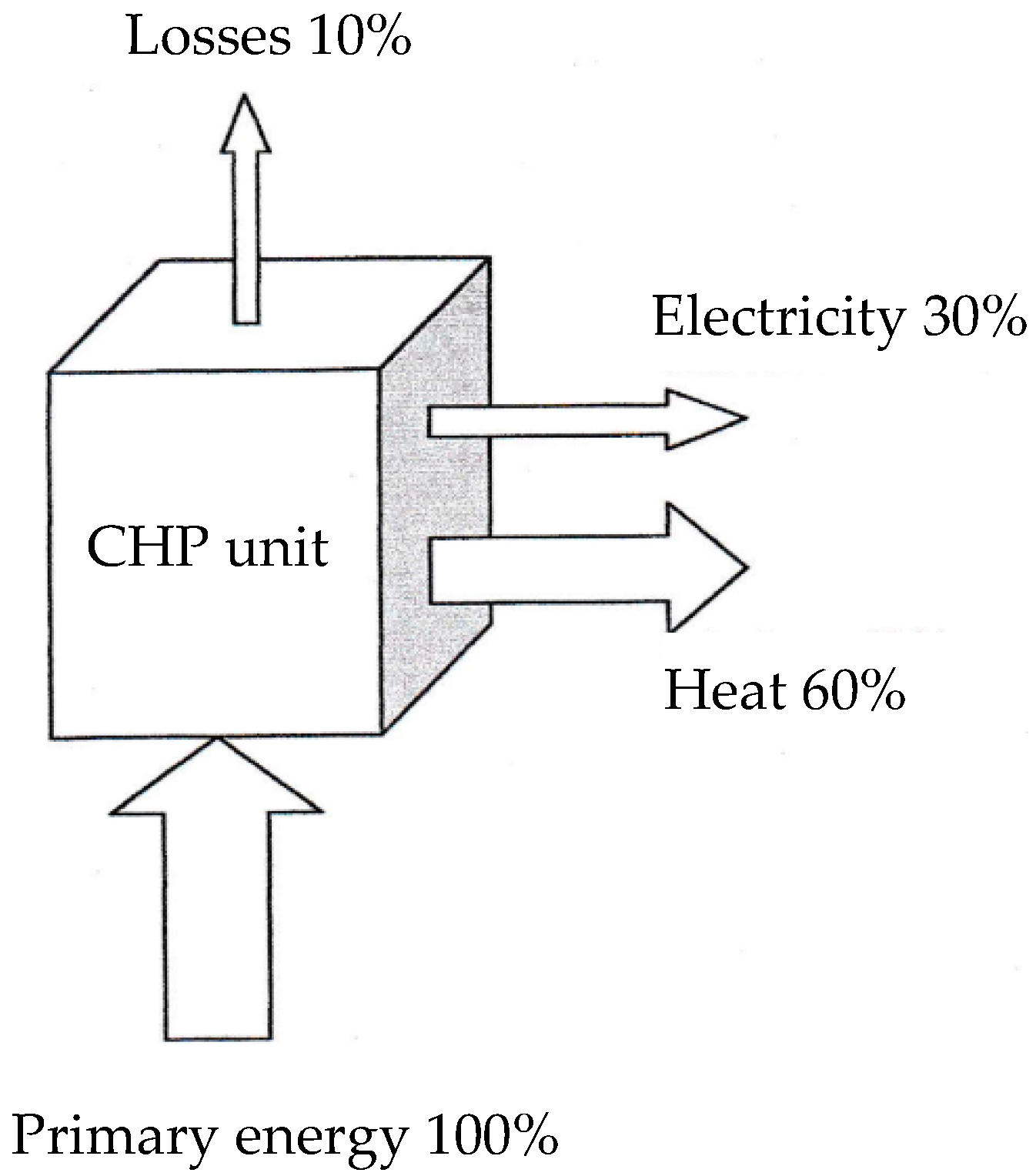
This combination of heat and power was the first one considered in the development of power production, based on the thermo-mechanical engines in industry.

2.1. Definition

Thermodynamics impose limitations to heat conversion in mechanical power, due to the impossibility of thermal machines to operate with only one heat reservoir (see Figure 1). Consequently, the heat is rejected in the environment that constitutes the heat sink (collecting the waste heat).
The primary energy is consumed at the hot heat source (i.e., by combustion of fuel).
The rejected heat from the unit could be split in two components:
  • The first one represents the unavoidable heat losses (roughly, 10%),
  • The second one is generally qualified as waste heat.
The alternative results from this scheme of CHHP, as follows:
  • The priority is the mechanical (electrical) noble part of the use.
In this case, part (or all) of the recuperated heat could be used, Qrecup.
2.
The priority is the useful heat (thermal energy), Qu, that represents a part of the combustion energy, Qcomb.
In this case, the remaining waste heat could be partially converted to mechanical energy.
In any case, by using the first law of thermodynamics, the first law efficiency could be expressed as:
η I ,     C H H P a = Q r e c u p + W Q c o m b
η I ,     C H H P b = Q u + W r e c u p Q c o m b
In summary, CHHP is the simultaneous production from primary energy (renewable or not) or with an energy carrier (from the same equipment) of heat and electricity (or more generally, work).
This corresponds to the definition given by ASHRAE (American Society of Heating, Refrigeration, and Air Conditioning Engineers). The same definition is given by CNRS (Centre National de la Recherche Scientifique), namely:
CHHP represents the simultaneous production of electricity or mechanical power and heat from a source of energy (oil, coal, natural gas).
More recently, the source of energy could be also solar, geothermal, or biomass [2].

2.2. Short History of CHHP [3,4,5,6]

The simultaneous use of mechanical and thermal energy started in industry during the 1880s by using a water vapor engine. The development of electrical motors jointly with the mechanical ones has boosted the use of electricity. Thus, at the beginning of the 20th century, a major part of electricity was associated with CHHP production. In 1900, 58% of electricity produced in USA was delivered by CHHP systems composed of a vapor turbine and a coal boiler.
The development of electrical networks has diminished the interest in CHHP in USA to 50% of the produced electricity used in industry (5% in 1974). Other factors have contributed to diminishing the use of this first CHHP configuration, mainly:
  • The centralized electricity production,
  • The low cost of fossil fuel until 1973 (first oil crisis).
It is why a new consideration of CHHP started after 1973 [2,7].
Since 1930, a new constraint related to environmental aspects appeared, concerning the limitation of greenhouse gas emissions.
Today, the energy management in USA, Europe, and Japan preconizes the use of CHHP, not only in industry, but also in the residential and tertiary domains [8,9,10,11,12]. In a seminar held in Paris, Löffler [13] proposed an analysis where the most important potential of developments was related to residential cogeneration systems, even with the most unfavorable scenarios.

2.3. Immediate Interest of CHHP

Figure 2 compares the order of magnitude of the reference conventional system with that of the basic CHHP system.
The order of magnitude of the primary energy saving for the same useful heat and electricity production is about 22%, with a CHHP efficiency close to 85%.
In fact, the European Union improved the comparison criterion [14]: “Each cogeneration unit shall be compared with the best available and economically justifiable technology for separation production of heat and electricity on the market in the year of construction of the cogeneration unit”.
In the case of France, this criterion is particularly due to the mix of energy, with nuclear electricity as the dominant one. Thus, the natural gas advantage, with respect to the greenhouse effect, disappears, implying the need to consider renewable energy, such as solar energy, biomass fueled CHHP systems [15], using biogas, and wood pellets [16]. Thus, NOx and SOx emissions must be added to CO2 emission in the environmental impact analysis of these systems.
In summary, the environmental constraint and the economical concern are strongly determinant for the development and use of CHHP systems. Table 1 reports a comparison of pollutants for classical CHHP configurations.
If natural gas is chosen as a reference, its combustion implies the production of water vapor and CO2, with the last one being the major greenhouse gas. This production is approximately 20% lower than the one produced by fuel oil combustion and approximately 40% lower than the one produced by coal combustion for the same thermal energy consumption.

3. Technologies of CHHP [3]

This section presents a summary of the four main types of centralized CHHP systems. Their schematic technical diagrams show the system components. The corresponding thermodynamic diagrams are available in [2,3,4,15]. Note that reference [3] is a French equivalent to the English publications and books on cogeneration published by ASME.

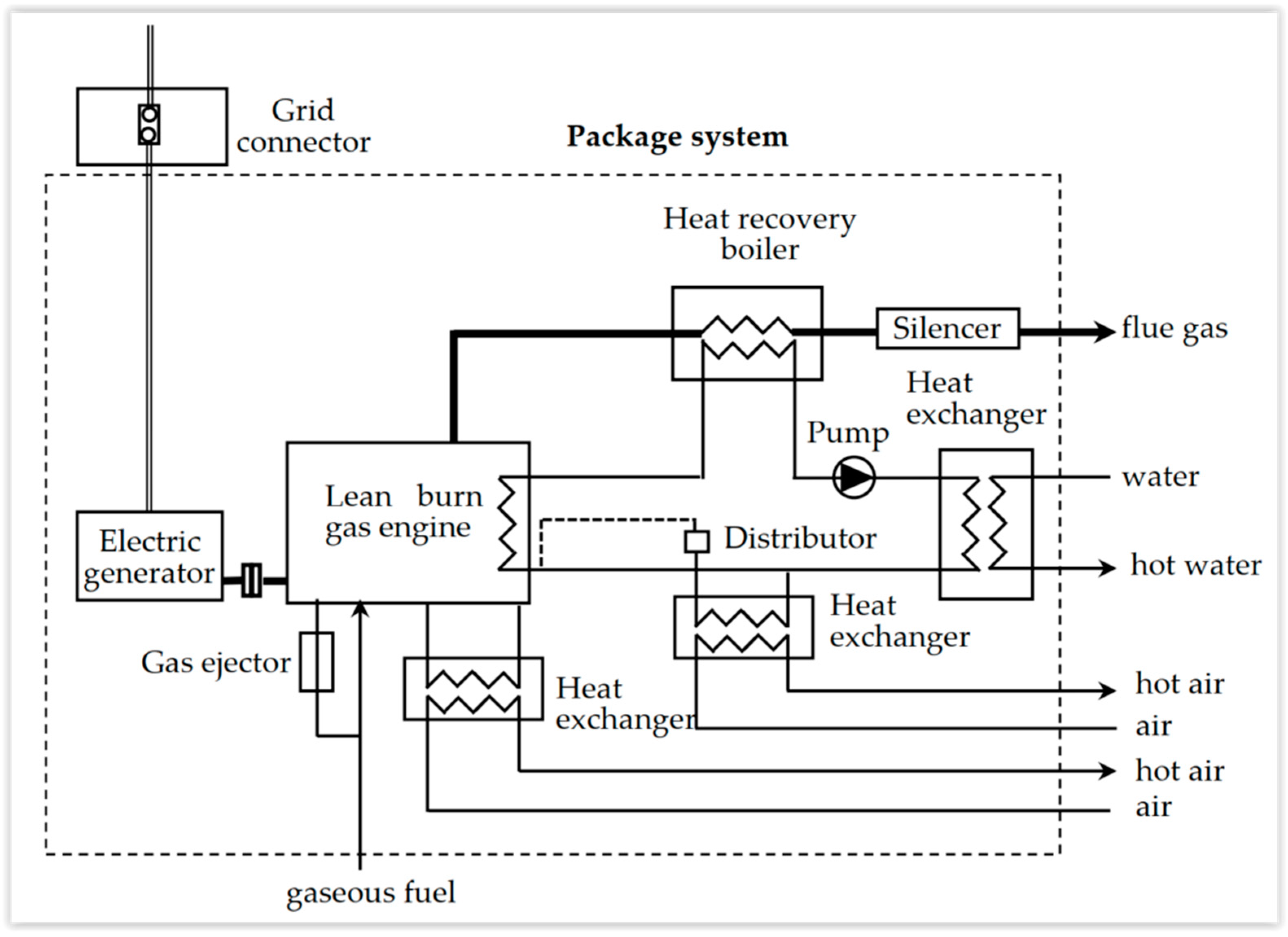
3.1. Gas Engine CHHP

This alternative uses an internal combustion engine fueled with natural gas or biogas.
Figure 3 illustrates the configuration of a gas engine CHHP. The engine could be fueled with natural gas from the network (at a pressure of 4 bar). Generally, the produced electricity is of low voltage or mean voltage for industrial applications (power).
Heat is recuperated as warm water from various heat exchangers: cooling lubricant, cooling exhaust gas (flue gases), cooling turbocharger. The main use seems to be in the tertiary domain, with 1 MW order of magnitude (building, hospital, university) [13].

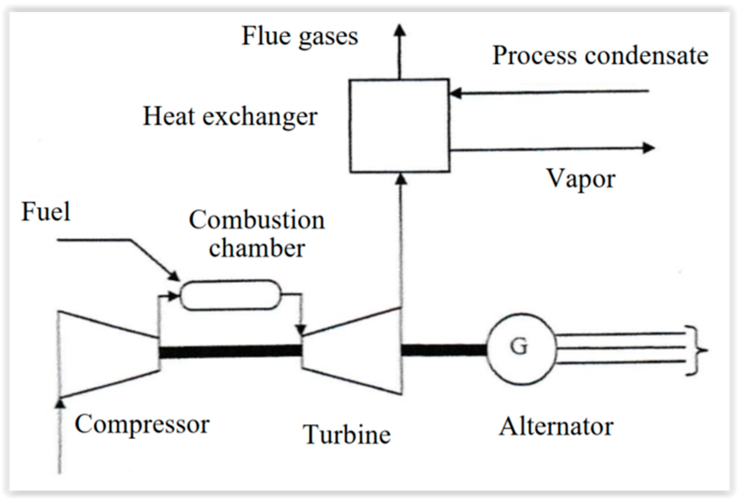
3.2. Gas Turbine CHHP [16,17,18,19,20,21]

Figure 4 represents such a system. The air is compressed (within the range 15 to 40 bar) in a turbocompressor, before being introduced in the combustion chamber, where it maintains the burning of liquid fuel or natural gas. After the combustion, the flue gas is expanded in the turbine coupled to the alternator to produce electricity. Part of the mechanical energy produced by the gas turbine is used to drive the compressor.
The exhaust gases (flue gases) are at 450–550 °C, while the combustion temperature is 850–1200 °C. Sensible heat could be recuperated in heat exchangers or within a post-combustion chamber.
Gas turbine engine CHHP is mainly used for power upper to 1 MW. Examples are available in the following sections. We indicate that the new tendency is to consider microturbines [18,19,20].

3.3. Diesel Engine

This CHHP configuration is interesting, due to the high value of the first law efficiency of the diesel engine over a large domain of power output, the flexibility of the fuel that can be used, and the large variety of CHHP configurations. The recuperated heat comes from three sources: (1) exhaust gases, (2) engine cooling water (around 110 °C) or low-pressure vapor (about 0.5 bar), (3) engine lubricant cooling.
The industrial use of this configuration is not so evident, but it is well-adapted for air conditioning systems. Generally, the diesel CHHP systems have a lower global first law efficiency, due to the low thermal recuperated heat associated with high mechanical efficiency.

3.4. Vapor Engine [7]

This CHHP configuration uses a back pressure vapor turbine (with an exit pressure higher than the ambient one) [7,20].
Its main use is in industry where it ensures the delivery of water vapor in the networks (generally at 3 bar or 12 bar). The water vapor could be also extracted during its expansion in the turbine [20].

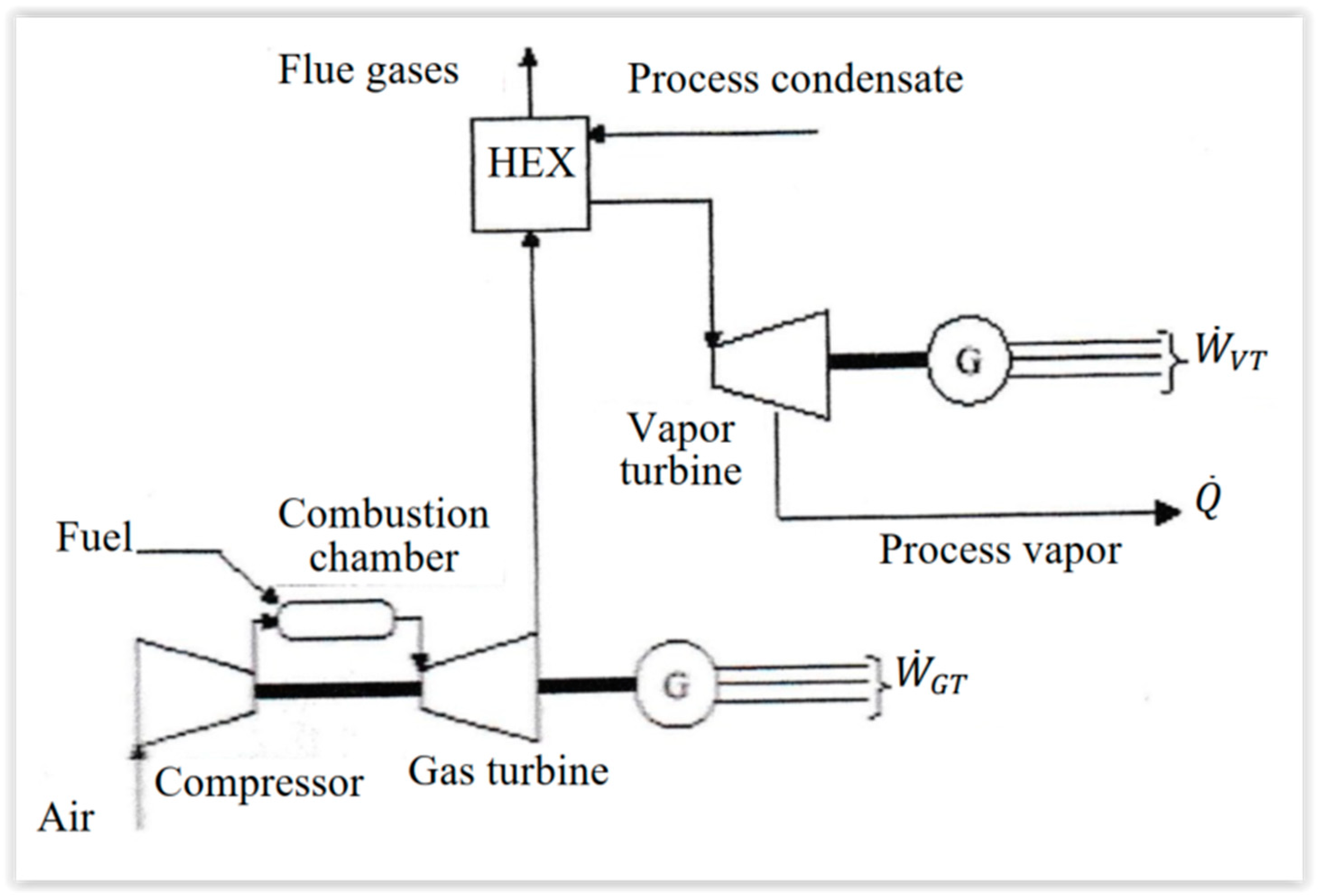
3.5. CHHP with Combined Cycles [20]

In this case, there is a coupling between a gas turbine and a vapor turbine (Figure 5). The heat rejection of the gas turbine is used to produce water vapor for the vapor turbine. Many variants of this system exist [20,21].
The high efficiency of the conversion from chemical (fuel) energy to the electrical one implies that the rejected heat from the gas turbine tends to be low, since the main interest is to produce water vapor for industrial use.

3.6. External Combustion Engine CHHP [22,23,24,25,26,27]

The two main types of external combustion engines are the Stirling [22,23] and Ericsson [22] configurations. These two cycles are also used for reverse cycle applications (cold production). Note that the Stirling configuration is present in more applications than the Ericsson one. A great advantage of these systems consists of the fact that external combustion control is easier with whatever fuel is used. Additionally, external heat source does not exclude other configurations, for example, solar ones [24]. Complementary references on the subject with specific configurations are given in [25,26,27].

3.7. Fuel Cells [28,29]

The most common fuel cell (FC) uses the reciprocal chemical transformation of water dissociation (electrolysis of water), according to:
H 2 + 1 2 O 2 H 2 O
where H2 is the fuel, and O2 is the oxidizer.
This chemical reaction is environmentally safe because it produces only water. The fuel H2 could also be produced from natural gas, liquefied petroleum gas (LPG), or other fuels by chemical reaction with the catalysis that is used to boost the electrochemical reaction.
Globally, the electrochemical reaction produces electrical energy and heat. The first law of efficiency for electrical production is around 50%, according to the fuel cell architecture.
If H2 is produced from a hydrocarbon species, CO2 emission is identical to one of the most performant diesel engines, due to the functional temperature of FC in the range of 80 °C for PEMFC (proton exchange membrane fuel cell) and 1000 °C for SOFC (solid oxide fuel cell), see Table 2. However, the rejection of NOx is suppressed, as well as the sulfur oxides.
The rejected heat recovery essentially depends on the level of temperature rejection. In this respect, SOFC [28,29] could turn a gas turbine, due to their high temperature rejection, and thus improve the first law efficiency for electricity production, always with an interesting level of temperature for the remaining heat rejection.
Even if FC are well-studied, their applications seem to remain rather demonstrative projects.

3.8. Comparison and Some Other Possibilities

Table 3 summarizes the advantages and inconveniences of the three main configurations of CHHP, apart from industrial uses.
More recently, some new configurations of CHHP appear, for example, based on solar energy conversion, namely:
  • Thermal configuration of solar CHHP, for example the dish Stirling [27] engine, where solar energy is the hot source ensuring heat to mechanical energy conversion,
  • Photovoltaic and thermal conversion (PVT).
This more recent approach considers the direct conversion of radiative solar energy to electricity, while the remaining heat could be used for air conditioning (heating or cooling), as well as hot water production.
Actually, the situation is very contrasted, due to the importance of the laws and specificities of nations. In France, the cogeneration is poorly used (3% around 2000), due to the high weight of nuclear energy in the electricity production. Thereby, cogeneration is used for the industry heat network and tertiary domain (hospital, buildings, university).
In Europe, according to Cogen Europe [30], the cogeneration in 2000 was 10% of the total production, with 50% in industry (chemistry, paper, petroleum industry). Eurostat [31] provides an interesting repartition of used fuel (Figure 6) and technologies (Figure 7).
Figure 6 shows that the most used fuel in EU is natural gas (47%), followed by coal and derived products (14%) and renewable fuel (12%), while the weight of the other fuels is below 10%.
Figure 7 confirms that the vapor turbine is dominant in the EU, with 73% of usage, since it is present in condensation turbines (12%), back pressure turbines (30%), and combined cycles (31%).

3.9. Considerations Regarding Efficiencies

3.9.1. First Law Efficiency of CHHP

The first law of efficiency of CHHP was introduced differently, since its expression depends on the priority of the useful effect given to (i) work or (ii) heat (particularly heat networks). A detailed discussion, and the corresponding expressions of the first law efficiency for these two cases, Equations (1a) and (1b), were provided in Section 2.
Figure 8 shows the first law efficiency values for different CHP power plants and the main cogeneration systems in EU countries, with the average of the 15 countries, followed by the distribution of each of them. It appears that the combined cycle efficiency is the highest in Denmark, Germany, Luxembourg, Sweden, and Finland, but modest on EU-15 (about 52%), while the CHHP using the back pressure turbine have the highest efficiency in Spain, France, Ireland, Italy, Netherlands, and UK, as well as an average on EU-15 (about 79%).
The configuration with condensation and steam extraction is less efficient, with an average of the first law efficiency about 42% for EU-15, but the criterion used is doubtful (see Section 8).

3.9.2. First Law Efficiency for Trigeneration

The general definition of the first law of efficiency in the case of trigeneration involves three useful effects:
  • Hot heat flux Q ˙ H , u ,
  • Cold heat flux Q ˙ C , u ,
  • Power output W ˙ , with the steady-state operation assumption.
The energy rate expense is generally heat flux, Q ˙ E . Thus, the first law efficiency expression for trigeneration is:
η I ,     t r i g e = Q ˙ H , u + Q ˙ C , u + W ˙ Q ˙ E .
The value of this efficiency is less than 1, due to the thermal losses rate Q ˙ L of the system and rejected heat rate, Q ˙ R . By considering these two heat rates, an equivalent expression of the first law efficiency for trigeneration results in:
η I ,     t r i g e = 1 Q ˙ R + Q ˙ L Q ˙ E .
Figure 9 illustrates a general scheme of the heat flow in a trigeneration system, starting with:
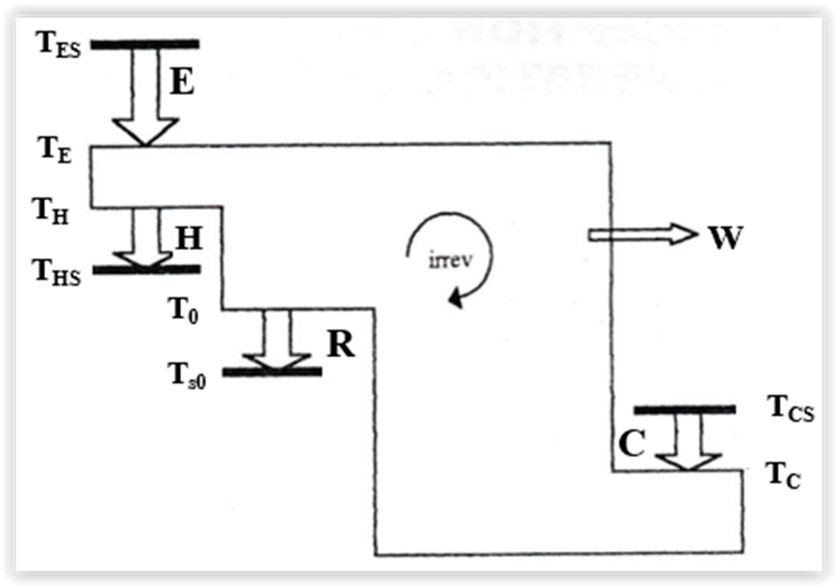
  • E—the primary heat, from the source to the system,
  • H—the hot heat delivery,
  • C—cold heat delivery,
  • R—heat rejected to the sink.
Note that the important issues associated with trigenerations are considered and discussed in [32].

3.9.3. Exergy Efficiency

The exergy efficiency indicator is a useful tool for maximizing the benefit and efficiently using the resources [33]. It allows us to emphasize the losses and internal irreversibilities leading to the reduction of the energy potential to produce useful effects.
It is well-known that the heat rate exergy is expressed as the product of the Carnot efficiency and the heat rate [33]:
E x ˙ Q = ( 1 T 0 T ) Q   ,
where T0 is the ambient temperature, and T is the temperature at which the heat transfer occurs.
Replacing the various heat rate terms in the first law efficiency (Equation (3)) with the corresponding heat rate exergy from Equation (5) provides the expression of the exergy efficiency for trigeneration:
η e x ,     t r i g e = ( 1 T 0 T H S ) Q ˙ H , u + ( T 0 T C S 1 ) Q ˙ C , u + W ˙ ( 1 T 0 T E S ) Q ˙ E ,
with THS, hot heat effect temperature > T0,
TCS, cols heat effect temperature < T0,
TES, primary heat effect temperature > THS.
This temperatures associated to the heat rates delivery are indicated by bold lines in Figure 9.
The exergy efficiency for CHHP will be defined in Section 8, where it will be used for optimization under different constraints of these systems.

4. Improvement of Classical Technologies

The improvement of the classical technologies proposed in the literature appear as a consequence of the standard development or the research development that will be discussed hereafter.

4.1. Standard Development

4.1.1. Internal Combustion Engine (ICE)

An inventory of ICE engine improvements, from an industrial point of view, is summarized hereafter. The technical documents provided by the manufacturers show that the improvements are not specific to the CHHP system, but rather related to engine improvements, oriented towards:
  • Fluid dynamics,
  • Combustion with the environment pollutants issue: CO2, NOx, VOC (Volatile Organic Compounds), particles),
  • Heat transfer,
  • Fuel replacement by biomass, biogas, H2,
  • Post-combustion (used by Bergerat- Monnayeur Energie),
  • Combined cycle (used by Wartsila).
This short list was completed with the information provided by two recent references. The first one [34] was related to point two of the list. The second one was related to fuels, correlating to a COMSOL day on hydrogen technologies and how the hydrogen industries are using multiphysics modeling and simulation to study and design fuel cells, electrolyzers, and reactors [35].
A new question arises, relative to the new version of electrical engine for the transport that induces a new paradigm: electrical energy engine generates heat by the Joule effect, but not sufficiently to assure the comfort in the vehicle in winter. Thus, it changes the objective from improving the mechanical conversion of heat to furnishing sufficient electricity, to assure human comfort in a car, or bus, or train.

4.1.2. External Combustion Engine (ECE) [22]

The situation is completely different regarding ECE: one moves from industry to research development, demonstration projects, and feasibility. The great majority of research developments are accomplished with Stirling engine configurations. The representative configuration is the dish Stirling one [27], but other configurations are possible [24].

4.1.3. Improvement of Gas Turbine (Combustion Turbine) [36,37,38]

Two main objectives are foreseen relative to the gas turbine improvement. The first one is the limitation of NOx emission, which is quite a challenge nowadays. It can be achieved via water injection or catalytic oxidizing.
The second point here is connected to the increase in the electrical/mechanical efficiency. Two ways are explored, namely:
(i)
Increasing the entrance gas temperature (to 1400 °C). It implies the use of new materials as thermal barriers for the turbine blades,
(ii)
Advanced thermodynamic cycles (used by Advanced Gas Turbine USA) [14].

4.1.4. Micro Turbines

Classically, gas turbine engines are distributed in three categories upon the power output range: industrial cogeneration, mini-cogeneration, and micro-cogeneration.
Here, we are interested in the middle category, with power less than 1 MW, which operates with mini turbines, i.e., Volvo Aero Turbines (UT 600: 600 kW), Turbec (VAT and ABB: 100 kW).
When the concern is micro-cogeneration, the combination of fuel cells (SOFC) with a gas turbine (GT) looks promising [29], with its electrical efficiency reaching high values (about 65%).

4.2. Research in Due Course

4.2.1. Internal Combustion Engine (ICE)

Actually, this point remains a difficult one, evolving rapidly. For transport, ICE will be replaced by the electric motor (see Tesla engine for USA). However, this seems to be a contradictory with the need of heat for air conditioning (hot in winter, cold in summer). In Europe, a new law is in discussion, with a deadline for ICE engine use in 2035.
Nevertheless, improvement of the first law efficiency of ICE remains a goal, but also the minimization of pollutant rejection. Biogas and biofuels are currently being tested as alternatives to fossil fuels.

4.2.2. External Combustion Engine (ECE)

We have seen (Section 4.1.2) that demonstration units of ECE have been tested in the recent past. However, more special configurations are envisaged, namely free piston engines [23,25,26].

4.2.3. Others

Gas turbines and fuel cells are extensively studied [21,28,29,39], and independently of system, biogas looks like a transition between oil and H2 to be developed, regardless the technology used.
Reference [16] illustrates the Gas Turbine flexibility regarding the fuels. Hybrid configurations of GT with FC have been tested for CHHP, either with PEMFC [28] or with SOFC [29]. Some experiments have also been performed with CCHP [39] for cold heat production.
In all these applications, some important influences are ignored. Very few papers deal with the transient conditions that are a necessary step to have instantaneous control of the system, whatever it is [37]. These transient conditions are of short duration, but when heat transfer is considered in heat exchangers, fouling appears a transient condition, but of a long time duration and connected to an important operating cost [38].

5. Constraints to Overcome

Some constraints are being more and more asserted in the field of environment and economy.

5.1. Economy and Law [39,40,41,42]

5.1.1. Matching between Offer and Demand

Production and needs are to be adjusted at any time in theory because the simultaneous need of heat and power are not correlated. Thus, a priority for heat or electricity production must be decided, or an alternative to provide energy storage, whatever is the form of energy for accommodation.
Here appears an interaction with the eventual networks (heat and/or electricity). In any case, the system could be conceived with the possibility to reject heat to the ambiance (waste heat). Another possibility is to adjust, in time, the cogeneration production because an electrical consumption peak is practically observed everywhere in the morning and in the evening (before people leave home, then when they are coming back). This fact is particularly solved in France, through micro-cogeneration with the corresponding configuration, named “cogenerative boiler”.

5.1.2. Maintenance and Autonomy

Regular maintenance is a must when the target is to get maximum operating efficiency from a CHP system. Life cycle analysis (LCA) could help to optimize the maintenance.
The autonomy of the system is another important issue. Even if this involves an additional investment cost, it could be mandatory, for example, in hospitals [10].

5.2. Scientific and Technical Constraints

These constraints are mainly connected to environmental aspects. Comments on the consequences of considering them are given hereafter.

5.2.1. For Engines

The two constraints lead to:
  • Homogeneous charge compression ignition (HCCI),
  • Downsizing,
  • Specific engines: stationary engine (dual fuel, co-combustion, solid fuel),
  • Corrosion reduction, lubrication aspects.

5.2.2. For Other Configurations

  • Diversification of heat production, having hot temperature heat pumps as a competitor [43],
  • Use of cascade: gas turbine/fuel cell.
Nevertheless, the existing limitations through the thermo-mechanical constraints (material constraint) must be mentioned in the two consequences presented above.

5.3. Perspectives of CHHP

Over the 20 last years, the scenario (optimistic) of P. Löffler from the research executive of COGEN Europe has indicated at the decentralized energy seminar (15–16 October 2002, in Paris) [13] that, at the European scale, the micro-cogeneration option starts to have a role, even in France, where the configuration is centralized. Figure 10 illustrates the development by sectors, as well as their development potential.
In terms of fuel, biomass and biogas join natural gas in importance.
As a partial conclusion and summary concerning CHHP, we give hereafter their classification upon the power output:
  • Big cogeneration, electric power > 1 MW,
  • Small-scale cogeneration, 215 kW–1 MW,
  • Mini-cogeneration, 36–215 kW,
  • Micro-cogeneration, <36 kW.
An important parameter is the ratio electricity/heat, E/Q since it involves the dimensioning of the CHHP system, according to priority.
In Europe, cogeneration moves from systems with back pressure turbines (in industry) to micro-cogeneration ones (with ECE-heat pump, ECE with biomass, stationary use of engine, H2 as a fuel).
Complementary information regarding CHHP can be found in [44,45,46,47,48,49,50,51].

6. Extensions of CHHP Concept

As seen previously, the CHHP systems are centered on two main objectives: electricity and hot heat uses, with a priority that could be devoted to electricity production in a great majority of applications, but could also be devoted to hot heat uses at temperatures above the ambient ones.

6.1. Cold CHP (CCHP)

Regarding the last examined period, a lot of works have been related to CCHP system [52,53,54,55,56], which is intended to pro-vide cold at a temperature below the ambient one. It can be a positive cold (with respect to 0 °C) that is useful for air conditioning [52,53]. However, CCHP can also furnish negative cold that corresponds to refrigerating applications, mainly for food conservation purposes: refrigeration, freezing, or deep-freezing.
The CCHP configuration can be:
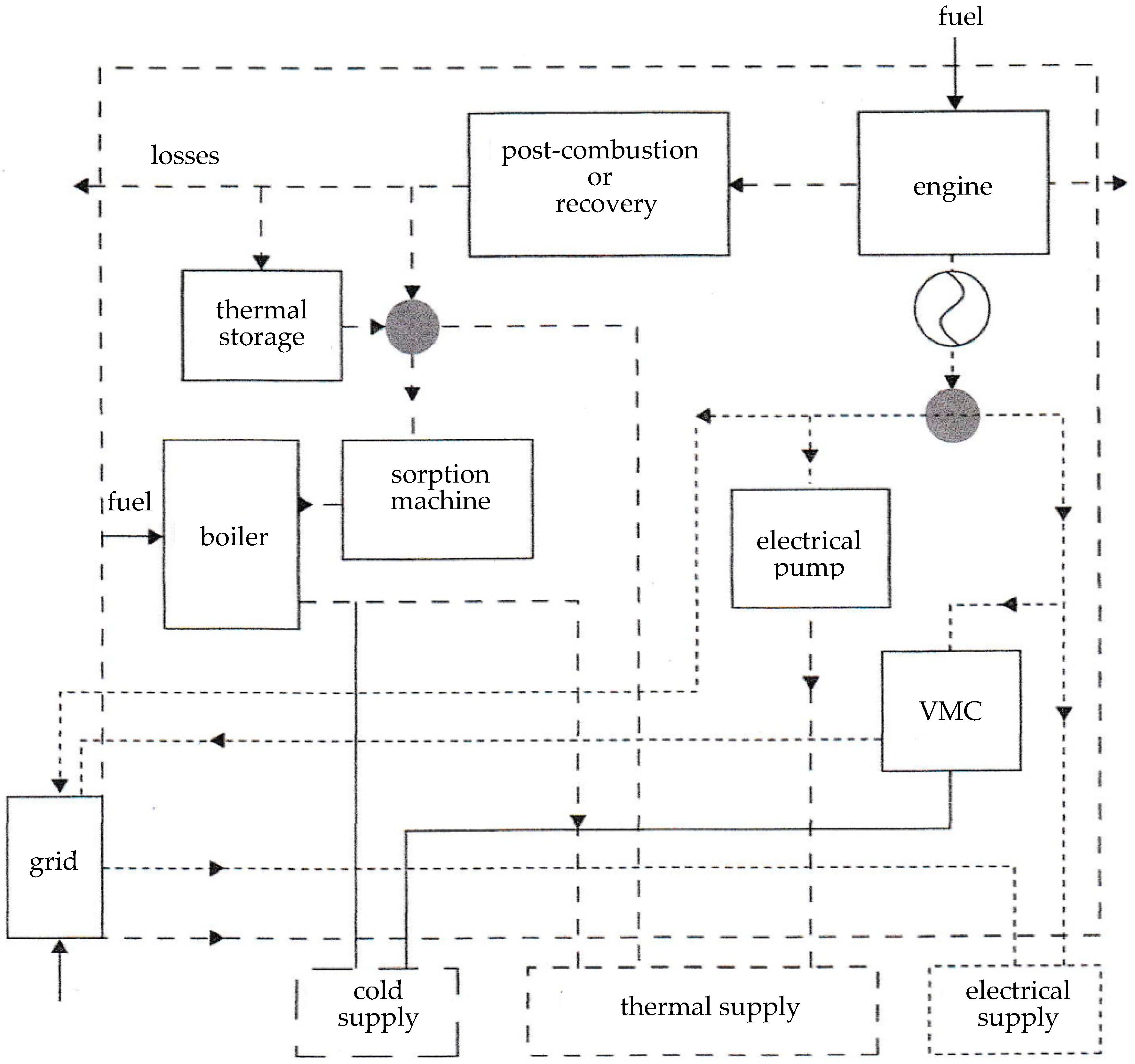
  • Direct CCHP with conventional vapor mechanical compression (CCHP with VMC),
  • CCHP with sorption machine, where the rejected heat is used to perform a thermal compression [38].
The most studied and industrialized machines are:
CCHP with sorption machine H2O-LiBr, if the temperatures are >5 °C,
CCHP with sorption machine NH3-H2O, if the temperatures are <5 °C.

6.2. Trigeneration System and More [32,57,58,59,60,61,62,63,64,65,66,67,68,69,70,71,72,73,74,75,76,77,78,79,80,81,82,83,84,85]

In the previous sections, the cogeneration was associated with two utilities, whatever they are. Here, besides electricity, the basic trigeneration supposes the needs of hot heat and cold heat. These last two utilities could be simultaneous or alternate in time.
A double effect trigeneration system for energy saving in the French Space Center is working at Toulouse for CNES (Centre National d’Etudes Spatiales). The center comprises 60 buildings (2500 persons). The site has major cooling requirements to cover the powerful computers’ cooling needs.
A trigeneration plant was installed in 2001, with natural gas powering the heat engines and generating electricity. The heat is recovered on the cooling circuit of the engines, and it is used for water heating, then additional heat recovery comes from the exhaust gas that feeds the cooling system providing water at 6 °C. The plant avoids consuming 7000 MWh of energy and emitting 19,000 tons of CO2 over a 12-year period. The initial cost was 3.85 MEuro, and it saved 668 kEuro per year. Subsidies (from ADEME-Agence de l’Environnement et de la Maîtrise de l’Energie and regional authorities) allowed for a return on investment in 5 years.
Figure 11 shows an evolved configuration of trigeneration.
The most interesting situation is when the two needs (hot and cold) are concomitant (for food industry and hospitals) [63,68].

6.3. Polygeneration

Poly-generation is a conceptual complement to trigeneration. This approach retained little consideration until recently, but probably more in the future, if considering its applications. Thus, we can indicate water production, compressed air, and thermal cascades.
Naturally, the prolongation to poly-generation provides a place for the integration of systems and processes [86]. This integration is better considered at the conception stage of an industrial park or of a district. The simplest integration is the combined cycles configuration, for example, the coupling between a gas turbine (GT) and vapor turbine (VT), implying an efficiency of the combined cycle, as follows:
η C C = η G T + ε ( 1 η G T ) η V T
where ε is the effectiveness of gas turbine waste heat HEX (heat exchanger).
We clearly notice an improved value of the first law of efficiency for the combined cycle. It determines a fuel economy and, consequently, a lower production of CO2 for the same electricity production.
More sophisticated configurations have been reported [15]. Many papers deal with multi-objective optimization, according to the specific cases that are proposed [87,88].

7. Insight into Environment and Economy

This section completes what has been reported in Section 5, showing that the initially perceived constraint becomes an objective.
The references show that, even for classical CHHP configurations, economical aspects are always important for engineers [3,4,5] by considering the economy as an objective and regulation [6] by the constraints, particularly the coming ones for the environment protection. These two aspects could not be ignored when also focusing on science (applied thermodynamics). It is about the influence of interconnexions of these various aspects, resulting in multi-objective optimization or constrained optimization. This approach is developed in Section 8, through thermodynamic models (of only CHHP system) that illustrate the methodology.

7.1. Environment

Depending on the analyzed paper, the environment could be considered a constraint or objective. During the last period, it became more of an objective. Additionally, Rosen [89] also added health as a benefit/constraint.
With this large-scale represented by the environment, the small-scale devices, the CHP systems, are in connection. Thus, Pehnt considers and discusses the environmental impacts of distributed energy systems in the case of micro-cogeneration [90].

7.2. Economy

The economy remains the main objective of engineers. It could be represented by the capital cost (CAPEX), related to investment, that should be minimized, as well as the operational cost (OPEX) to minimize.
In fact, in the previous presentation, we have only considered OPEX through the maximization of useful energy. A new criterion could be to minimize the ratio of OPEX divided by the useful energy. More details can be found in [91], reporting on the thermo-economic analysis of CHP with gas turbines. Actually, this paper presents an exergo-economic analysis of CHP. We will develop exergetic aspects in the following section.
The same demarch was previously used by Lazaretto and Toffolo [92]. These authors have considered three objectives in the multicriteria optimization of thermal system design, namely energy, economy, and environment. They have used an evolutionary algorithm to find the optimum, according to a Pareto front, and have illustrated the method with the CGAM problem [93]. This study was improved for the CGAM problem by Sayyaadi [94], considering a multi-objective approach in thermo-environomic optimization.
The interest for micro-CHP systems was reported in Germany and in Japan [95], as well.
Ren and Gao have considered different operating modes of micro-CHP systems for residential buildings or households.
The fuel cell system is better than the gas engine one, in terms of minimum operating cost and minimum pollutant emission. In our opinion, this demarch has to be developed and completed in the future from an engineering point of view, since it is more concerned with specific case studies and numerical (computerized) methods [93]. In fact, the economic optimization deserves to be performed on global cost, that is, the sum of CAPEX and OPEX on the lifetime of the installation. Thus, this global cost, related to the lifetime, recovers as a byproduct the LCA (life cycle analysis) to characterize durability, recycling, and other environmental concern.
It seems that exergo-economics remains to be considered and developed [96,97]. We notice that, in fact, these two papers are devoted to the improvement methods of the system. However, this is not truly an optimization in the mathematical sense. This is not the case of weighting methodology [78], where the sensitivity to the distribution of the weighting coefficients must be checked.
Many other methods to optimize the CHP system exist, among them, we cite the linear programming method. For more insight, see [98], or its English translation [99,100].

8. Thermodynamic Models of CHHP System

In this section we will focus on:
  • The basic thermodynamical modeling, according to the literature, but with emphasis on efficiency criterion and on exergy as important concepts,
  • The determination of upper bounds of these criteria to certify the quality of CHHP systems, in contrast with quantity. In other words, the quantity of valorized energy is better represented by the exergy that combines intensity and extensivity.

8.1. The Exergy Concept

Many papers are concerned with the exergy concept used in the analysis and optimization of CHHP [101]. This approach is powerful and indispensable because from, the energy point of view, the heat is the unique form of energy that is degraded, since it is a noncoherent or disordered form of energy versus coherent energy (all other forms of energy).
It means that, when we dispose of the quantity Q of heat at a given temperature T, only a part of this heat (noncoherent energy) can be converted in noble energy (coherent energy).
In an environment at temperature T0, the maximum mechanical energy W (availability), if T > T0, is:
E x = W = Q ( 1 T 0 T )   .
Remark 1.
If the medium temperature is T < T0, we obtain:
E x = W = Q ( T 0 T 1 )   .
In this second case, W represents the minimum mechanical energy necessary to transfer the heat from T to T0 (higher potential), with a cold production at T.
The case of trigeneration is a combination of the two preceding ones.
Additionally, the expression of heat must be specified, due to the difference between latent heat and sensible heat, since in the second case, Q becomes a function of the temperature level T.

8.2. The Exergy Efficiency

We enlarge here the definition given in Section 2 and focus on the most common CHHP configuration with heat engine (Figure 12) [102,103]. The simplified engine is the Carnot one.
With the steady state hypothesis (nominal regime for dimensioning purpose), the energy balance corresponds to:
Q ˙ C = W ˙ + Q ˙ U + Q ˙ L   ,
with
Q ˙ C = Q ˙ H + Q ˙ L   ,
where Q ˙ H is the hot heat flux entering the engine,
Q ˙ L is the heat flux losses between hot and cold side,
Q ˙ C is the heat flux consumed,
W ˙ is the power output of the engine.
Consequently, the first law efficiency is expressed as:
η I ,     C H H P = W ˙ + Q ˙ U Q ˙ C = 1 Q ˙ L Q ˙ C .
Thus, the first law efficiency appears as an adiabatic efficiency, whatever the thermo-mechanical system.
In fact, the useful energy flux Q ˙ U is supposed to be delivered at temperature TU. Consequently, the useful exergy flux for heat is expressed by:
E x ˙ U = W ˙ + ( 1 T 0 T U ) Q ˙ U .
By using the same approach for any thermo-mechanical engine, we define the consumed exergy flux as:
E x ˙ C = Q ˙ C ( 1 T 0 T S H ) ,
where TSH is the source temperature supposed constant (thermostat).
Note that, if the source has a finite thermal capacity (variable temperature), a different approach should be adopted by using entrance temperatures and effectiveness of the heat exchangers or mean logarithmic temperatures [98,99,100].
The exergy efficiency is defined as:
η e x ,     C H H P = E x ˙ U E x ˙ C .
Note that this efficiency differs from that of Grassmann, who considers the useful output exergy rates, divided by the input exergy rates [32]:
η e x ,     G = E x ˙ o u t E x ˙ i n .

8.3. Upperbound in the Case of Linear Heat Transfer

The linear heat transfer approximation (or Newton heat transfer law) relates the gradient of temperature and the heat transfer conductance Ki (hot or cold side), according to:
Q ˙ i = K i ( T i S T i )   .
A common upper bound is relative of the endo-reversible case that is represented in Figure 12 for the Carnot engine (see [102]).
In [103], an expression of the exergetic efficiency for the Carnot CHHP, when the cycle is endo-reversible and without heat losses, was obtained:
η e x ,     C H H P = ( 1 T 0 T C T U T H ) ( 1 T 0 T S H ) ,
where TC is the temperature of the cycled fluid during the heat transfer at the cold side.
The finite rate of the heat transfer imposes a constraint between the two variables, TU and TC, that are provided by the entropy balance of the engine:
Q ˙ H T H + Q ˙ U T C = 0 .
In the case of linear heat transfer lows, the maximization of the useful exergy flux has been performed via two-step optimization using the Lagrangian method. The first step is relative to temperatures TH, TC (only one degree of freedom left). The second step is relative to thermal conductances, KH, KC, with the finite dimension constraint (only one degree of freedom left again):
K H + K C = K T   ,
where KT is the total heat transfer conductance to be allocated and essentially connected to the investment cost.
The corresponding maximum of the useful exegy flux is [102,103]:
M a x   E x ˙ u = K T 4 ( T H S T 0 ) 2 .
This second step of optimization delivers the equipartition of heat transfer conductances:
K H * = K C * = K T 2   .
This result is a consequence of the endo-reversibility of Carnot cycle.

8.4. General Results regarding the Optimization with Constraints

As mentioned previously, the use and design of the CHHP system is characterized by the ratio of the useful heat flux to the useful power R = Q ˙ U W ˙ , where R could be a constraint.
We may also need a given power W ˙ , a given useful heat flux Q ˙ U , or an imposed (limited) heat flux consumed Q ˙ C .
Any of these constraints suppresses a degree of freedom. The corresponding results are available in [103].
The interesting result is that M a x   E x ˙ U remains associated with the optimum of the useful effect, whatever the concerned engine may be. It confirms that the endo-reversible case, with constraints or not, is a reference case, since:
M a x   E x ˙ U does not depend on TU,
M a x   E x ˙ U is proportional to KT (size of the system),
M a x   E x ˙ U is increasing with TSH, but this temperature is limited by the material maximum thermal strength.
Additionally, we note that, for a non-adiabatic system, a new third optimum exists, which is limited by the stagnation temperature [104].
Extension to irreversible CHHP has been performed by using the irreversibility ratio method [103]. The results of this approach are summarized in Table 4.
This table clearly proves that the equipartition of heat transfer conductances does not hold in the irreversible conditions.

9. Conclusions—Perspectives

This review allows for drawing major conclusions and suggesting some perspectives.
  • CHHP systems use mainly combustion engines, even if some other configurations are studied and tested with renewable sources, such as biofuel or solar, which can be thermal or photovoltaic.
  • The best criteria for CHHP systems are related to exergy efficiency.
  • More insight has been put on CHHP options, namely the cogeneration, trigeneration, polygeneration, and integration of systems and processes.
  • Optimization, with respect to the finite physical dimensions of the system (FDOT), has been performed. Note that this was not allowed through equilibrium thermodynamics.
  • Optimization has been performed with various complementary constraints: R, W ˙ , Q ˙ U , Q ˙ C , useful for dimensioning. However, very few works deal with dynamic optimization (transient conditions), which is necessary for control–command of the system.
  • In any case, heat rejection (waste heat) remains. How to valorize the waste heat?
  • A proposal of an upper bound (maximum maximorum) of the useful exergy flux, associated with endo-reversible case, was presented. This upper bound constitutes a reference exergy that could be used in the future.
To summarize the discussions, two directions of the work clearly appear:
  • An engineering approach related to technology,
  • A scientific approach for the characterization and comparison of various CHP configurations, as well as to complement the research.
From this review, proof emerges that the use of exergy or exergo-economic analysis is mandatory to characterize and compare CHP configurations. The exergy efficiency is an appropriate criterion by its non-dimensionality. Additionally, the analyzed references show the existence of an exergetic or economic optima, when CAPEX, OPEX, global cost, or LCA are considered.
Finally, the approach of the CHHP system presented in Section 8 introduces an upper bound based on exergy analysis, whose results are independent of the constrained studied case (Table 4). This result remains to be further extended by considering other heat transfer laws, different from the linear one, or by an extended analysis, also involving the environmental efficiency. The goal for the future is to precisely facilitate a comparison of any system with an ad-hoc criterion leading to optimal design and control.

Author Contributions

Conceptualization, M.F.; methodology, M.F.; software, M.C.; validation, M.F. and M.C.; formal analysis, M.F. and M.C.; writing—original draft preparation, M.F.; writing—review and editing, M.C.; visualization, M.F. and M.C.; supervision, M.F.; project administration, M.C. All authors have read and agreed to the published version of the manuscript.

Funding

This research received no external funding.

Conflicts of Interest

The authors declare no conflict of interest.

References

  1. Bachelard, G. The Psychoanalysis of Fire, 2nd ed.; Idée-Galimard: Paris, France, 1949. (In French) [Google Scholar]
  2. Lallemand, A. Cogeneration; Report for the interdisciplinary Energy program of the CNRS (Thematic Analysis Group no. 4, GAT 2E: Energy Efficiency); Centre National de la Recherche Scientifique (CNRS): Paris, France, 2005. (In French) [Google Scholar]
  3. Levy, C. Cogeneration techniques. Tech. De L’ingénieur 1996, B8910, 20. (In French) [Google Scholar]
  4. Levy, C.; Tabet, J.P. Cogeneration in air-conditioning engineering—Technical aspects. Tech. De L’ingénieur 1999, BE9340, 13. (In French) [Google Scholar]
  5. Levy, C.; Tabet, J.P. Cogeneration in air-conditioning engineering—Results. Tech. De L’ingénieur 1999, BE9342, 8. (In French) [Google Scholar]
  6. Levy, C.; Tabet, J.P. Cogeneration in air-conditioning engineering—Rentability and regulation. Tech. De L’ingénieur 1999, BE9341, 13. (In French) [Google Scholar]
  7. Remy, P.M.; Boissenin, Y.M.; Moliere, M.M. Combustion turbine and cogeneration facilities with complex architecture: Example of the Metz electricity plant. Int. J. Thermal Sci. 1994, 396, 717–725. (In French) [Google Scholar]
  8. Chicherin, S.; Zhuikov, A.; Kolosov, M.; Junussova, L.; Aliyarova, M.; Yelemanova, A. Temperature and flow rates dynamics in a district heating (DH) network fed by a combined heat-and-power (CHP) plant. Energy Rep. 2021, 7, 327–333. [Google Scholar] [CrossRef]
  9. Magnani, S.; Pezzola, L.; Danti, P. Design Optimization of a Heat Thermal Storage Coupled with a Micro-CHP for a Residential Case Study. Energy Procedia 2016, 101, 830–837. [Google Scholar] [CrossRef]
  10. Szklo, A.S.; Soares, J.B.; Tolmasquim, M.T. Energy consumption indicators and CHP technical potential in the Brazilian hospital sector. Energy Convers. Manag. 2004, 45, 2075–2091. [Google Scholar] [CrossRef]
  11. Zabalza, I.; Aranda, A.; de Gracia, M.D. Feasibility analysis of fuel cells for combined heat and power systems in the tertiary sector. Int. J. Hydrogen Energy 2007, 32, 1396–1403. [Google Scholar] [CrossRef]
  12. Campos-Celador, A.; Pérez-Iribarren, E.; del Portillo-Valdés, L.A. Thermoeconomic analysis of a micro-CHP installation in a tertiary sector building through dynamic simulation. Energy 2012, 45, 228–236. [Google Scholar] [CrossRef]
  13. Löffler, P. Research Executive GOGEN EUROP. In Proceedings of the Communication in Seminar on Decentralized Energy, Paris, France, 15 October 2002. (In French). [Google Scholar]
  14. European Directive, Energy Efficiency Calculation, Primary Energy Saving. Directive 2004/8/EC of the European Parliament and Council of 11 February 2004. Available online: https://eur-lex.europa.eu/legal-content/EN/ALL/?uri=celex%3A32004L0008 (accessed on 7 July 2022). (In French).
  15. Dong, L.; Liu, H.; Riffat, S. Development of small-scale and micro-scale biomass-fueled CHP systems—A literature review. Appl. Therm. Eng. 2009, 29, 2119–2126. [Google Scholar] [CrossRef] [Green Version]
  16. Thiers, S.; Aoun, B.; Peuportier, B. Experimental characterization, modelling and simulation of a wood pellet micro-combined heat and power unit used as a heat source for residential building. Energy Build. 2010, 42, 896–903. [Google Scholar] [CrossRef]
  17. Costea, M.; Feidt, M.; Alexandru, G.; Descieux, D. Optimisation of gas turbine cogeneration system for various heat exchanger configuration. Oil Gas Sci. Technol. 2012, 67, 517–535. [Google Scholar] [CrossRef] [Green Version]
  18. Sepehr, S.; Masoud, Z.; Maziar, G. Optimal design of gas turbine CHP plant with preheater and HRSG. Int. J. Energy Res. 2009, 33, 766–777. [Google Scholar]
  19. Postelnicu, V. Micro Cogeneration—Micro Gas Turbine. Master’s Thesis, National Polytechnic Institute of Lorraine, Nancy, France, 2003. (In French). [Google Scholar]
  20. Cenusa, V. Contribution to the improvement of the Thermodynamic Coupling between the Gas Turbine Installation and the Steam Turbine Installation of A Gas-Steam Combined Cycle Power Plants. Ph.D. Thesis, University Henri Poincaré (Lorraine University now), Nancy, France, 25 October 2006. (In French). [Google Scholar]
  21. Starfelt, F.; Yan, J.Y. Case study of energy systems with gas turbine cogeneration technology for industrial peek. Int. J. Energy Res. 2008, 12, 1128–1135. [Google Scholar] [CrossRef]
  22. Stouffs, P. Micro cogeneration: Choice of heat engine. Bul. Inst. Poli. Iasi 2010, 56, 3a. Machine Construction section. (In French) [Google Scholar]
  23. Boucher, J.; Garcia Burel, I.; Lanzetta, F.; Nika, P. Parametric study of the performance of a Duval-type free-piston cogenerator. In Proceedings of the French Thermal Congress SFT 2007, Île des Embiez, France, 29 May–1 June 2007; pp. 1139–1144. (In French). [Google Scholar]
  24. Mathieu, A. Contribution to the Conception and Thermodynamic Optimization of A Solar Thermoelectric Micro Power Plant. Ph.D. Thesis, Lorraine University, Nancy, France, 23 May 2012. (In French). [Google Scholar]
  25. Mikalsen, R.; Roskilly, A.P. A review of free-piston engine history and applications. Appl. Thermal Eng. 2007, 27, 2339–2352. [Google Scholar] [CrossRef]
  26. Francois, P.; Garcia Burel, I.; Ben Ahmed, H.; Prevond, L.; Multon, B. 3D Analytical model for a tubular linear induction generator in a Stirling cogeneration system. In Proceedings of the IEEE IEMDC, Antalya, Turkey, 3–5 May 2007; pp. 392–397, hal-00676232. [Google Scholar]
  27. Schaechtele, K.; Nepveu, F.; Ferriere, A. Technical and Economic Study of the Dish-Stirling System: Methodology Based on a Multi-Criteria Analysis Technique; Report PROMES-CNRS: Paris, France, 2006. (In French) [Google Scholar]
  28. Radulescu, M. Electricity Cogeneration System with Pemfc or Sofc Type Fuel Cell and Internal Reforming. Ph.D. Thesis, University Henri Poincaré (Lorraine University now), Nancy, France, 25 September 2006. (In French). [Google Scholar]
  29. Gay, C. Improving the Energy Efficiency of the Vehicle of the Future: Stirling Engine/Sofc Fuel Cell Association. Ph.D. Thesis, University of Franche Comté, Besançon, France, 19 October 2008. (In French). [Google Scholar]
  30. Europe, C. A Guide to Cogeneration; Technical Report; Cogen Europe: Brussel, Belgium, 2000. [Google Scholar]
  31. Quel Futur Pour L’humanité. Available online: htttp://www.quelfutur.org/consommationeurope.html (accessed on 7 July 2022). (In French).
  32. Feidt, M.; Lang, S. Optimal design of combined systems generating power, heat, force. Entropie 2002, 242, 2–11. (In French) [Google Scholar]
  33. Dincer, I.; Zamfirescu, C. Advanced Power Generation Systems, 1st ed.; Elsevier: Amsterdam, The Netherlands, 2014; pp. 27–49. [Google Scholar]
  34. Dilber, V.; Sjeric, M.; Tomic, R.; Krajnovic, J.; Ugrinic, S.; Kozarac, D. Optimization of Pre-Chamber Geometry and Operating Parameters in a Turbulent Jet Ignition Engine. Energies 2022, 15, 4758. [Google Scholar] [CrossRef]
  35. Bernard, F. COMSOL Day: Hydrogen Technologies. Available online: https://www.comsol.com/c/dkml (accessed on 13 October 2022).
  36. Wang, S.; Li, B. Thermodynamic Analysis and Optimization of a Novel Power-Water Cogeneration System for Waste Heat Recovery of Gas Turbine. Entropy 2021, 23, 1656. [Google Scholar] [CrossRef]
  37. Manikyala Rao, A.V.R.N.B.; Kumar Singh, A. Optimization and Control of renewable Energy Integrated Cogeneration Plant Operation by Design of Suitable Energy Storage System. Energies 2022, 15, 4590. [Google Scholar] [CrossRef]
  38. Jradi, R.; Marvillet, C.; Jeday, M.R. Fouling in industrial Heat Exchangers: Formation, Detection and Mitigation. In Heat Transfer; Kazi, S.N., Ed.; Open access peer-reviewed chapter; Intechopen: London, UK, 2021. [Google Scholar] [CrossRef]
  39. Clausse, M.; Meunier, F.; Coulié, J.; Herail, E. Comparison of adsorption systems using natural gas fired fuel cell as heat source, for residential air conditioning. Int. J. Refrig. 2009, 32, 712–719. [Google Scholar] [CrossRef] [Green Version]
  40. Alves, L.G.; Nebra, S.A. Thermoeconomic evaluation of a basic optimized chemically recuperated gas turbine cycle. Int. J. Thermodyn. 2003, 6, 13–22. [Google Scholar]
  41. Romary, D. Technical-Economic Study of Production and Distribution of Heat and Power: Application to the Tertiary. Ph.D. Thesis, University Henri Poincaré (Lorraine University now), Nancy, France, 26 October 2001. (In French). [Google Scholar]
  42. El-Masri, M.A. On the thermodynamics of gas turbine cycle: Part 1—Second law analysis of combined cycles. J. Eng. Gas Turbine Power 1985, 107, 880–889. [Google Scholar] [CrossRef]
  43. Lallemand, A.; Luo, L.; Gicquel, R. Comparative study of heat production by cogeneration or heat pump. In Proceedings of the 4th International Conference on Energy and Environment, CIEM 2009, Bucharest, Romania, 19–20 November 2009; Section 2. p. 12. [Google Scholar]
  44. Dupleac, R.; Tazerout, M.; Mahieu, V.; Rousseau, S.; Leduc, B. Experimental database for a cogeneration gas engine efficiency prediction. Proc. Inst. Mech. Eng. A J. Power Energy 2001, 215, 55–62. [Google Scholar] [CrossRef]
  45. Jalalzadeh-Azar, A.A. A comparison of electrical and thermal load following CHP systems. ASHRAE Trans. 2004, 110, 85–94. [Google Scholar]
  46. Yilmaz, T. Optimization of cogeneration systems under alternative performance criteria. Energy Convers. Manag. 2004, 45, 939–945. [Google Scholar] [CrossRef]
  47. Erdil, A. Exergy optimization for an irreversible combined cogeneration cycle. J. Energy Inst. 2005, 78, 27–31. [Google Scholar] [CrossRef]
  48. Hawkes, A.; Leach, M.A. Impact of temporal precision in optimization modelling of micro-Combined Heat and Power. Energy 2005, 30, 1759–1779. [Google Scholar] [CrossRef]
  49. Atmaca, M.; Gumus, M.; Inan, A.T.; Yilmaz, T. Optimization of irreversible cogeneration system under alternative criteria. Int. J. Thermophys. 2009, 30, 1724–1732. [Google Scholar] [CrossRef]
  50. Onovwiona, H.I.; Ugursal, V.I. Residential cogeneration systems: Review of the current technology. Renew. Sustain. Energy Rev. 2006, 10, 389–431. [Google Scholar] [CrossRef]
  51. Rentizelas, A.; Karellas, S.; Kakaras, E.; Tatsiopoulos, I. Comparative technical economic analysis of ORC and gasification for bioenergy applications. Energy Convers. Manag. 2009, 50, 674–681. [Google Scholar] [CrossRef] [Green Version]
  52. Wang, J.; Dai, Y.; Sun, Z. A theoretical study on a novel combined power and ejector refrigeration cycle. Int. J. Refrig. 2009, 32, 1186–1194. [Google Scholar] [CrossRef]
  53. Landoulsi, H.; Elakhdar, M.; Nehdi, E.; Kairouani, L. Performance analysis of a combined system for cold and power. Int. J. Refrig. 2015, 60, 297–308. [Google Scholar] [CrossRef]
  54. Kong, X.Q.; Wang, R.Z.; Huang, X.H. Energy efficiency and economic feasibility of CCHP driven by Stirling engine. Energy Convers. Manag. 2004, 45, 1433–1442. [Google Scholar] [CrossRef]
  55. Cho, H.; Mago, P.J.; Luck, R.; Chamra, L.M. Evaluation of CCHP systems performance based on operational cost, primary energy consumption and carbon dioxide emission by utilizing an optimal operational scheme. Appl. Energy 2009, 86, 2540–2549. [Google Scholar] [CrossRef]
  56. Mago, P.J.; Fumo, N.; Chamra, L.M. Performance analysis off CCHP and CHP systems operating following the thermal and electrical load. Int. J. Energy Res. 2009, 33, 852–864. [Google Scholar] [CrossRef]
  57. Deng, I.; Wang, R.; Wu, J.; Han, G.; Wu, D.; Li, S. Exergy analysis of a micro cogeneration system based on the structural theory of thermoeconomics. Energy 2008, 33, 1417–1426. [Google Scholar] [CrossRef]
  58. Kong, X.Q.; Wang, R.Z.; Li, Y.; Huang, X.H. Optimal operation of a micro combined cooling, heating and power system driven by a gas engine. Energy Convers. Manag. 2008, 50, 530–538. [Google Scholar] [CrossRef]
  59. Li, S.; Wu, J.Y. Theoretical research of a silica gel-water absorption chiller in a micro combined cooling, heating and power (CHHP) system. Appl. Energy 2009, 86, 958–967. [Google Scholar] [CrossRef]
  60. Cardona, E.; Piacentino, A. A methodology for sizing a trigeneration plant in Mediterranean areas. Appl. Thermal Eng. 2003, 23, 1665–1680. [Google Scholar] [CrossRef]
  61. Cardona, E.; Piacentino, A. A new approach to exergoeconomic analysis and design of variable demand energy systems. Energy 2006, 31, 490–515. [Google Scholar] [CrossRef]
  62. Chicco, G.; Mancarella, P. A unified model for energy and environmental performance assessment of natural gas fueled poly-generation systems. Energy Convers. Manag. 2008, 49, 2069–2077. [Google Scholar] [CrossRef]
  63. Bassols, J.; Kuckelkorn, B.; Langreck, J.; Schneider, R.; Veelken, H. Trigeneration in the food industry. Appl. Thermal Eng. 2002, 22, 595–602. [Google Scholar] [CrossRef]
  64. Minciuc, E.; Le Corre, O.; Athanasovici, V.; Tazerout, M. Fuel saving and CO2 emissions for tri-generation systems. Appl. Thermal Eng. 2003, 23, 1333–1346. [Google Scholar] [CrossRef]
  65. Minciuc, E.; Le Corre, O.; Athanasovici, V.; Tazerout, M.; Bitir, I. Thermodynamic analysis of tri-generation with absorption chilling machine. Appl. Thermal Eng. 2003, 23, 1391–1405. [Google Scholar] [CrossRef]
  66. Cardona, E.; Piacentino, A.; Cardona, F. Energy saving in airports by trigeneration. Part I: Assessing economic and technical potential. Appl. Thermal Eng. 2006, 26, 1427–1436. [Google Scholar] [CrossRef]
  67. Wu, D.W.; Wang, R.Z. Combined cooling, heating, and power: A review. Progr. Energy Combust. Sci. 2006, 32, 459–495. [Google Scholar] [CrossRef]
  68. Ziher, D.; Poredos, A. Economics of a trigeneration system in a hospital. Appl. Thermal Eng. 2006, 26, 680–687. [Google Scholar] [CrossRef]
  69. Chicco, G.; Mancarella, P. Trigeneration primary energy saving evaluation for energy planning and policy development. Energy Policy 2007, 35, 6132–6144. [Google Scholar] [CrossRef]
  70. Lin, L.; Wang, Y.; Al-Shemmeri, T.; Ruxton, T.; Turner, S.; Zeng, S.; Huang, J.; He, Y.; Huang, X. An experimental investigation of a household size trigeneration. Appl. Thermal Eng. 2007, 27, 576–585. [Google Scholar] [CrossRef]
  71. Chicco, G.; Mancarella, P. Assessment of the greenhouse gas emission from cogeneration and trigeneration systems. Part I: Models and indicators. Energy 2008, 33, 410–417. [Google Scholar] [CrossRef]
  72. Arteconi, A.; Brandoni, C.; Polonara, F. Distributed generation and trigeneration: Energy saving opportunities in Italian supermarket sector. Appl. Thermal Eng. 2009, 29, 1735–1743. [Google Scholar] [CrossRef] [Green Version]
  73. Ezzahiri, S.M.; Ferreira, C.A.I.; Krieg, J.; Gerwen, R.V. Solar-assisted combined heat and power refrigeration system. Bull. IIF-IIR 2009, 6, 14–20. [Google Scholar]
  74. Glisic, I.; Vuckovic, G.; Sretenovic, A. Energy savings using trigeneration on Business and Hotel Complex “Airport City Belgrade”. In Proceedings of the ECOS Conference, Faz de Iguaçu, Brazil, 31 August–3 September 2009; pp. 719–728. [Google Scholar]
  75. Sugiartha, N.; Tassou, S.A.; Chaer, I.; Marriot, D. Trigeneration in food retail: An energetic, economic and environmental evaluation for a supermarket application. Appl. Thermal Eng. 2009, 29, 2624–2632. [Google Scholar] [CrossRef] [Green Version]
  76. Marques, R.P.; Hacon, D.; Tessarollo, A.; Reis Parise, J.A. Thermodynamic analysis of trigeneration system taking into account refrigeration, heating and electricity load demands. Energy Build. 2010, 42, 2323–2330. [Google Scholar] [CrossRef]
  77. Al-Sulaiman, F.A.; Dincer, I.; Hamdullahpur, F. Exergy modeling of a new solar driven trigeneration system. Sol. Energy 2011, 85, 2228–2243. [Google Scholar] [CrossRef]
  78. Angrisani, G.; Roselli, C.; Sasso, M. Distributed micro cogeneration systems. Progr. Energy Combust. Sci. 2012, 38, 502–521. [Google Scholar] [CrossRef]
  79. Martins, L.N.; Fabrega, F.M.; d’Angelo, J.V.H. Thermodynamic performance investigation of a trigeneration cycle considering the influence of operational variables. Procedia Eng. 2012, 42, 1879–1888. [Google Scholar] [CrossRef] [Green Version]
  80. Rocha, M.S.; Andreos, R.; Simoes-Moreira, J.R. Performance tests of two small trigeneration pilot plants. Appl. Thermal Eng. 2012, 41, 84–91. [Google Scholar] [CrossRef]
  81. Ucok, T.; Akdemir, O.; Gungor, A. Performance assessment of a trigeneration system in a supermarket. In Proceedings of the 6th International Ege Energy Symposium & Exhibition, İzmir, Turkey, 28–30 June 2012; pp. 298–307. [Google Scholar]
  82. Vallianou, V.A.; Frangopoulos, C.A. Dynamic optimization of a trigeneration system. Int. J. Thermodyn. 2012, 15, 239–247. [Google Scholar]
  83. Ata, C.; Ali, S.M.; Mohammad, S.; Mortaza, Y.; Leyla, K. Greenhouse gas emission and thermodynamic assessments of an integrated trigeneration system based on SOFC driving a GAX absorption refrigeration system as a subsystem. In Exergy for a Better Environment and Improved Sustainability 1. Green Energy and Technology; Aloui, F., Dincer, I., Eds.; Springer: Cham, Switzerland, 2018. [Google Scholar] [CrossRef]
  84. Buonomano, A.; Calise, F.; Palombo, A.; Vicidomini, M. Energy and economic analysis of a geothermal-solar trigeneration system: A case study for a hotel building in Ischia. Appl. Energy 2015, 138, 224–241. [Google Scholar] [CrossRef]
  85. Wang, J.; Wu, J. Investigation of a mixed effect absorption chiller powered by jacket water and exhaust gas waste heat of internal combustion engine. Int. J. Refrig. 2015, 50, 193–206. [Google Scholar] [CrossRef]
  86. Feidt, M. Energy Engineering; Dunod: Paris, France, 2014; Chapter 19. (In French) [Google Scholar]
  87. Rong, A.; Lahdema, R. An efficient linear programming model and optimization algorithm trigeneration. Appl. Energy 2005, 82, 40–63. [Google Scholar] [CrossRef]
  88. Wang, J.J.; Jing, Y.Y.; Zhang, C.F. Weighting methodologies in multi-criteria evaluation of combined heat and power systems. Int. J. Energy Res. 2009, 33, 1023–1039. [Google Scholar] [CrossRef]
  89. Rosen, M.A. Energy, environmental, health and cost benefit of cogeneration from fossil fuels and nuclear energy using the electrical utility facilities of a province. Energy Sustain. Dev. 2009, 13, 43–51. [Google Scholar] [CrossRef]
  90. Pehnt, M. Environemental impacts of distributed energy systems—The case of micro cogeneration. Environ. Sci. Policy 2008, 11, 25–37. [Google Scholar] [CrossRef]
  91. Ionita, C.; Marinescu, M.; Dobrovicescu, A.; Vasilescu, E.E. Thermoeconomic analysis of a combined heat and power system. Bul. Inst. Poli. Iasi 2010, 56, 125–134, Machine Construction section. [Google Scholar]
  92. Lazaretto, A.; Toffolo, A. Energy, economy, and environment as objectives in multicriteria optimization of thermal system design. Energy 2004, 29, 1139–1157. [Google Scholar] [CrossRef]
  93. Toffolo, A.; Lazaretto, A. Evolutionary algorithms for multi-objective energetic and economic optimization in thermal system design. Energy 2002, 17, 549–567. [Google Scholar] [CrossRef]
  94. Sayyaadi, H. Multi-objective approach in thermoenvironomic optimization of a benchmark cogeneration system. Appl. Energy 2009, 86, 867–879. [Google Scholar] [CrossRef]
  95. Ren, H.; Gao, W. Economic and environmental evaluation of micro CHP system with different operating modes for residential building in Japan. Energy Build. 2010, 42, 853–861. [Google Scholar] [CrossRef]
  96. Sahoo, P.K. Exergoeconomic analysis and optimization of a cogeneration system using evolutionary programming. Appl. Therm. Eng. 2008, 28, 1580–1588. [Google Scholar] [CrossRef]
  97. Abusoglu, A.; Kanoglu, M. Exergoeconomic analysis and optimization of combined heat and power production: A review. Renew. Sustain. Energy Rev. 2009, 13, 2295–2308. [Google Scholar] [CrossRef]
  98. Feidt, M. Thermodynamics and Energy Optimization of Systems and Processes, 3rd ed.; Lavoisier: Paris, France, 2016; Chapter 10. (In French) [Google Scholar]
  99. Feidt, M. Finite Physical Dimensions Optimal Thermodynamics 1. Fundamental; ISTE Press; Elsevier: London, UK, 2017. [Google Scholar]
  100. Feidt, M. Finite Physical Dimensions Optimal Thermodynamics 2. Complex. Systems; ISTE Press; Elsevier: London, UK, 2018. [Google Scholar]
  101. Ertesvåg, I.S. Exergetic comparison of efficiency indicators for combined heat and power (CHP). Energy 2007, 32, 2038–2050. [Google Scholar] [CrossRef]
  102. Feidt, M. Two examples of Exergy Optimization Regarding the ‘’Thermo-Frigopump’’ and Combined Heat and Power Systems. Entropy 2013, 15, 544–558. [Google Scholar] [CrossRef] [Green Version]
  103. Feidt, M.; Costea, M. Energy and Exergy Analysis and Optimization of Combined Heat and Power Systems. Comparison of Various Systems. Energies 2012, 5, 3701–3722. [Google Scholar] [CrossRef] [Green Version]
  104. Feidt, M. Optimal Thermodynamics—New Upperbounds. Entropy 2009, 11, 529–547. [Google Scholar] [CrossRef]
Figure 1. Principle of cogeneration (the values are only given as indicatives) [2].
Energies 15 08782 g001
Figure 2. Comparison of the cogeneration unit performance with that of the conventional system [2].
Energies 15 08782 g002
Figure 3. Schematic diagram of a gas engine cogeneration unit [16].
Energies 15 08782 g003
Figure 4. Scheme of a CHHP with Gas Turbine engine [17].
Energies 15 08782 g004
Figure 5. Combined cycle Gas Turbine + Vapor Turbine and cogeneration [20].
Energies 15 08782 g005
Figure 6. Use of different types of fuel [31].
Energies 15 08782 g006
Figure 7. Electricity production distribution among different CHP systems in EU [31].
Energies 15 08782 g007
Figure 8. First law efficiency of different CHP systems in EU [31].
Energies 15 08782 g008
Figure 9. Scheme of a general trigeneration configuration [32].
Energies 15 08782 g009
Figure 10. Cogeneration use in different sectors [30].
Energies 15 08782 g010
Figure 11. Trigeneration configuration with gas engine and vapor mechanical compression machine (VMC).
Energies 15 08782 g011
Figure 12. Non-adiabatic Carnot engine as the topping cycle of CHHP.
Energies 15 08782 g012
Table 1. Comparison of the gaseous pollutant emissions, according to the processes of electrical energy production.
Emissions for 1 kWhCO2 [kg]SO2 [g]NOx [g eq NO2]
Coal power plant (1% S)0.957.502.80
Fuel oil power plant (1% S)0.8051.80
Nuclear power plant000
Cogeneration GT 1 with coal0.574.401.17
Cogeneration GT with fuel oil0.462.930.99
1 Gas Turbine.
Table 2. Different types of Fuel Cells and their performance.
Type of FCPAFCPEMFSOFCMCFC
FuelHydrogen, natural gas, methanol, biogas
ApplicationsCogeneration,
public transport
Residential or tertial cogeneration, automobile, phone, underwater laptop, spaceCogeneration, decentralized electricity production
Development stageSmall series production; 200 unities of 200 kWe operating in the worldDevelopment: unities of 50 to 250 kWeR&D: units of a few kWe to 1 MWeRecherche: 1 unit of 2 MWe, several of 100 to 250 kWe
Power200 kWe for cogeneration
100 kWe for transport
Miniature FC of a few W for camcorder, road signs
<10 kWe for residential, 250 kWe for cogeneration
10 kWe or 300 kWe to a few MWe, depending on technologies250 kWe to a few MWe
Operating temperature200 °C80 to 120 °C800 to 1000 °C650 °C
Electrical efficiency40%35 to 40%45 to 50%
70% if coupled with turbines
45 to 50%
ConstructorOnsi (USA), Fuji Electric (Japan)Ballard + Alstom (Canada), Siemens,..Siemens\Weistinghouse (AII\USA), Rolls Royce (GB), Sulzer (Swiss)HC power (USA), Ansaldo (Italy), MTU (All)
Table 3. Comparison of three cogeneration systems.
Cogeneration SystemGas TurbineGas EngineDiesel Engine
Power range1–230 MW0.2–5 MW0.15–10 MW
Fuel usedHeavy oil, kerosene, biogasLPG, biogasHeavy oil, kerosene
Flue gas temperature500–600 °C400–600 °C350–400 °C
Cooling water temperature-80–90 °C70–75 °C
Efficiency of the electricity production25–40%28–38%30–45%
Total efficiency60–85%60–80%40–70%
Table 4. Carnot CHHP system optimization with constraints by using the irreversibility ratio (I) method.
Optimum→
Constraint↓
TH, optTC, opt | E x ˙ u | o p t
without I T S H T S H + T 0 I + 1 T U T 0 T S H + T 0 I + 1 K T ( I + 1 ) 2 ( T S H I T 0 ) 2
Q ˙ H = Q ˙ H 0 T S H Q ˙ H 0 K H T U 1 1 I Q ˙ H 0 K C   T H Q ˙ H 0 [ 1 I T 0 T S H Q ˙ H 0 ( 1 + I ) 2 K T   ]
R = R0 I 1 + I ( T S H + T U I 1 + R 0 R 0 ) 1 1 + I [ R 0 ( 1 + R 0 ) I T S H + T U ] K T   ( I + 1 ) 2 [ T S H I 1 + R 0 R 0 T U ] · [ 1 R 0 T 0 ( 1 + R 0 ) T U ]
W ˙ = W ˙ 0 T S H 1 + α o p t I T U 1 α o p t W ˙ 0 + K T T U I 1 + I ( 1 T 0 T U ) · α o p t 1 α o p t
Q ˙ U = Q ˙ U 0 T S H 1 + α o p t I T U 1 α o p t K T T S H 1 + I α o p t I + α o p t + Q ˙ U 0 T 0 T U
Publisher’s Note: MDPI stays neutral with regard to jurisdictional claims in published maps and institutional affiliations.

