Article

Performance Evaluation of a Solar Heat-Driven Poly-Generation System for Residential Buildings Using Various Arrangements of Heat Recovery Units

1
Mechanical Engineering Department, College of Engineering, Najran University, P.O. Box 1988, Najran 61441, Saudi Arabia
2
Department of Mechanical Power Engineering, Faculty of Engineering, Mansoura University, El-Mansoura 35516, Egypt
3
Department of Mechanical and Materials Engineering, Faculty of Engineering, University of Jeddah, Jeddah 21589, Saudi Arabia
4
Department of Mechanical Engineering, Benha Faculty of Engineering, Benha University, Benha 13511, Egypt
5
Department of Applied Mechanical Engineering, College of Applied Engineering, Muzahimiyah Branch, King Saud University, P.O. Box 800, Riyadh 11421, Saudi Arabia
6
Department of Mechanical Engineering, Faculty of Engineering at Shoubra, Benha University, Cairo 11629, Egypt
7
Department of Mechanical Engineering, College of Engineering at Yanbu, Taibah University, Yanbu Al-Bahr 41911, Saudi Arabia
8
Department of Chemical Engineering, College of Engineering at Yanbu, Taibah University, Yanbu Al-Bahr 41911, Saudi Arabia
*
Authors to whom correspondence should be addressed.
Energies 2022, 15(22), 8750; https://doi.org/10.3390/en15228750
Submission received: 15 October 2022 / Revised: 7 November 2022 / Accepted: 17 November 2022 / Published: 21 November 2022

Abstract

:
Poly-generation systems are a feasible alternative to conventional energy production techniques in buildings. A poly-generation system allows for the concurrent production of electricity, heat, cold, and fresh water, with considerable advantages regarding technology, finances, energy recovery, and the environment. In the present study, the organic Rankine cycle (ORC), the humidification–dehumidification desalination system (HDH), and the desiccant cooling system (DCS) are merged with three unique solar-driven poly-generation systems (BS, IS-I, and IS-II) and numerically examined. The proposed options provide energy, space cooling, domestic heating, and potable water to buildings of small/medium scale. Using n-octane ORC working fluid, the impact of operational circumstances on system productivity and execution characteristics was considered. The findings show that (i) the suggested poly-generation systems can provide electrical power, conditioned space cooling, local heating, and fresh water, whereas keeping the conditioned area pleasant, (ii) the IS-I system achieves the best system performance among all compared arrangements (BS and IS-II); (iii) the attained extreme values of W ˙ n e t , m ˙ f r e s h , Q ˙ c o o l i n g , Q ˙ h e a t i n g , and TGOR are 102.0 kW (all systems), 214.70 kg/h (IS-II), 29.940 kW (IS-II), 225.6 kW (IS-I), and 0.6303 (IS-I), respectively.

1. Introduction

Interest in renewable-energy-fueled poly-generation technology as a feasible replacement for common methods of energy production has increased. Poly-generation technology had many potential uses, especially for in-building micro- and medium-scale systems. It is beneficial from a technology standpoint and good for the economy, the environment, and energy conservation. Growth in industry and population have brought into focus the need for more resources, including energy, fresh water, and cooling, to support human needs [1]. Long-term solutions to energy, fresh water, and cooling/heating production demands, particularly in buildings, can be found in renewable energy sources. The future viability of energy production is threatened by two major issues: energy supply availability and global warming. Therefore, it is more important than ever to switch to renewable energy resources and create additional energy-efficient and environmentally friendly technology. The use of fossil fuels and CO2 emissions can be reduced using hybrid solutions based on renewable energy sources [2,3,4,5,6].
Cogeneration systems, which generate electricity and purified water, have recently been proposed for urban structures. Furthermore, renewable energy sources have attracted increased attention. The ORC can draw from a wide variety of sources, including temperature variations and alternative power sources. Connecting a thermal desalination system to an ORC enables more efficient use of the ORC’s internal flows and waste heat to power the desalination process [7,8,9,10]. Researchers [11,12,13] have combined ORC and HDH water desalination systems in various hybrid system designs to generate electricity and potable water. A desiccant air conditioner is used to combat the issue of rising temperatures, as it does not release harmful gases such as chlorofluorocarbons. A combination of air conditioning, desalination equipment, and renewable energy sources was employed to drastically cut down on electricity use. Numerous studies [14,15] have been conducted on the HDH desalination system in combination with a hybrid desiccant air conditioner. Multiple designs of a hybrid cooling and freshwater production system using heat pump units have been explored in previous research [16,17,18]. Herein, we examined various system configurations, operational factors, and geometric features.
By simultaneously cooling, heating, and generating electricity, tri-generation systems cut down on the need for main energy sources and the release of greenhouse gases. The blended cooling and heating of a tri-generation approach is superior to that of a conventional HVAC system, as shown by Wang et al. [19]. Multigenerational housing was reported by Ahmadi et al. [20]. The system provides heating, cooling, energy, hydrogen, and hot water. Multigeneration from waste heat may boost energy efficiency by 60% and exergy efficiency by nearly double. Mohammadi and Ameri [21] employed energo-exergetics to determine the optimal GT tri-generation parameters. They proposed a tri-generation system that can fulfill a building’s 100 kW cooling demand. The prime mover might be an MGT, GT, or SOFC (SOFC), with 37% increased efficiency relative to a regular single-generation AC system. Ambient, generator, and building temperatures have all been studied. Liu et al. [22] combined ORCs with GEHPs (engine-driven heat pumps) to deliver heating, warm water, cooling, and electricity to structures. There are a number of ORC fluids, including R245fa, R152a, and R123. More than half of energy comes from the waste heat produced by internal combustion engines. The ORC structure’s maximum thermal and exergy efficiencies come from R123 (11.84% and 54.24%, respectively).
Multigenerational techniques and technologies are required to improve worldwide energy efficiency, increase renewable energy suppliers, decrease CO2 releases, and reduce electrical scheme overloads [23,24]. Tri-generation is employed in commercial and industrial structures [25]. Rare researchers attempted to simulate tri-generational structures that include renewable energy with power, cooling, and fresh water. Zhang et al. [26] examined a solar biomass tri-generation structure that delivers warm water, electricity, and chilled water. To evaluate the effect of crucial operational elements, they simulated and analyzed the function of the tri-generation technique. Maraver et al. [27] examined a biomass system that can provide power, water, air conditioning, and ventilation. Although electric efficiency increases for every studied fluid, the heat created in the ORC condenser for desalination restricts the system’s ability to save power compared to more conventional methods. Thermoelectric generators were the focus of Islam et al.’s [28] research into a solar-powered, multigenerational system design. We compared two potential outcomes. In the solar heat transfer module, increasing the mass flow rate of the running fluid boosted the turbine and thermoelectric work.
A solar and geothermic poly-generation plant that provides a small hamlet with electricity, thermal energy, cooling, and potable water was investigated by Calise et al. [29]. The moderate-enthalpy geothermic ORC and the parabolical trough solar field make up the hybrid system. A distillation unit is heated by geothermal fluid, which then desalinates seawater. Two thermodynamically distinct concepts for a geothermal tri-generation system were examined by Zare [30]: one utilizing an ORC and the other employing a Kalina cycle. An absorption chiller using LiBr/water and a water heater is connected to the ORC and Kalina cycles to provide cooling and heating, respectively.
Electricity, fresh water, space cooling, and industrial heating can all be provided by a multigeneration system investigated by Azhar et al. [31]. This system uses geothermal, solar, and oceanic thermal energy, with a total efficiency of 13.93 percent in expressions of both energy used and created. A solar desiccant air-cooled, three-generation power plant was the subject of evaluation in another study. Under ideal conditions, solar-powered desiccant cooling fulfilled 35% of the building’s cooling load. Ghorbani et al. [32] proposed a tri-generation factory comprising a solar collector field, a Kalina power cycle, and a desalination unit that generates 65,194 kW of heat, 83.22 kg/s of fresh water, and 1869 kW of electricity. Baghernejad et al. [33] studied multiobjective optimization elements of tri-generation power systems. Abdelhay et al. [34] investigated a multigeneration system comprising solar power, multieffect desalination, and absorption refrigeration (ARS). The recommended incorporated system has the least part water charge (12,470 $/m3), lowest cooling unit cost (USD 0.0030/kWh), and highest energy efficiency (23.950%). Dabwan et al. [35] created a conceptual and analytic technique for combination of linear Fresnel reflector (LFR) knowledge with conventional cooling, clean water, and electric energy tri-generation systems.
Yao et al. [36] built a new tri-generation factory for incorporated heating, cooling, and electricity centered on compressed air energy storage knowledge. Choosing the optimum tradeoff approach resulted in 53.04% exergy efficiency and 20.54 cents/kWh product unit cost. Gholizadeh et al. [37] created a distinctive tri-generation system that produces fresh water, electricity, and cooling, employing a geothermic heat source at 170 °C. The optimization resulted in gains of 77.08% in turbine output power, 87.01% in cooling load, 8.18% in TGOR, and 46.36% in exergy efficiency. Bellos and Tzivanidis [38] optimized a tri-generation system for solar-powered structures. The best possible setup achieved 11.260 exergy efficiency and 87.39 energy efficiency. A total of 4.6 kW electricity, 7.10 kW cooling, and 59.40 kW of heating can be generated. Gholizadeh et al. [39] proposed a biogas-fueled tri-generation approach to produce electricity, cooling, and potable water. Total power, TGOR, cooling, and exergy efficiency were improved by 2.580%, 14.040%, 22.690%, and 13.260%, respectively, after optimization of the system.
The yearly energy output of a home-based hybrid renewable energy system was enhanced by Ghorab et al. [40]. The constructed system provided sufficient heating and cooling for the structure during the year. In the heating and cooling periods, an earth-source heat exchanger provided 21.3% of the total energy needed. Cascaded power and CO2 cooling are two components of the geothermal tri-generation concept proposed by Li et al. [41] in a system that generates 451.80 kW of electricity, 297.80 kW of heat, and 2.2740 kg/h of hydrogen each hour.
Recently, Fouda et al. [42] studied a tri-generation structure providing electricity, AC, and water desalination. The intended structure involves an ORC, DCS, an HDH water desalination system, a solar system (with abandoned tube accumulators and a thermal energy storage element), and other elements. The recommended tri-generation system provides 104.5 kW of electrical power, 25.480 kW of space cooling, 72.370 kg/h of fresh water, and 0.26430 EUF.
In our literature review, we identified few tri-generation structures for power, clean water, and cooling capacity coupled with HDH/ORC/ECC and MED/SRC/ARS and numerous cogeneration structures incorporated with ORC/HDH and DCS/HDH. This has led to a lack of research on poly-generation systems. Small and medium-sized structures are the focus of a novel poly-generation system that utilizes ORC, DCS, and HR components to produce electricity, cooling/heating for indoor spaces, and potable water, respectively. ORC power production is viable in cold environments [43]. Its benefits include minimal-temperature energy utilization (such as discarded power or solar energy), the ease of use of the HDH water desalination system, and low operational and capital expenditures [44]. Instead of using harmful gases such as chlorofluorocarbons, which are released by conventional air conditioners, desiccant air conditioners use water to cool the air. Owing to the constraints of traditional systems, we are motivated to explore the design, process, and performance of poly-generation structures that can supply small and medium-sized buildings with nonstop daylight electrical power, fresh water, and space cooling/domestic heating by means of solar energy.
To the best of our knowledge, no previous study has investigated such cutting-edge systems. In this paper, we propose and thermodynamically assess three poly-generation systems: ORC, DCS, and HDH. Utilizing thermodynamic and parametric evaluations, we assess the influence on the systems’ production and execution metrics. One “baseline” system [42] and two “enhanced” systems, along with several heat retrieval technologies, are presented and compared to one another to establish which system is the most effective. Thermodynamic cycles of the system are simulated and studied with the help of the Engineering Equation Solver (EES). In this paper, we provide the subsequent benchmarks to evaluate the proposed system designs, including (i) mathematical modeling of energy systems in contrast with unrelated structures, (iii) a description of how altering settings of parameters influences the efficiency and effectiveness of the suggested system (ε), and (iv) analysis the effectiveness of the suggested system in contrast to the original. Owing to its environmental and economic viability for providing electricity, domestic heating, space cooling, and fresh water for final consumers, particularly for small and moderately sized constructions, the results of the planned combined ORC, DCS, and HDH poly-generation structures are expected to entice care and profit investigators, solar poly-generation designers, power plant creators, and investors.

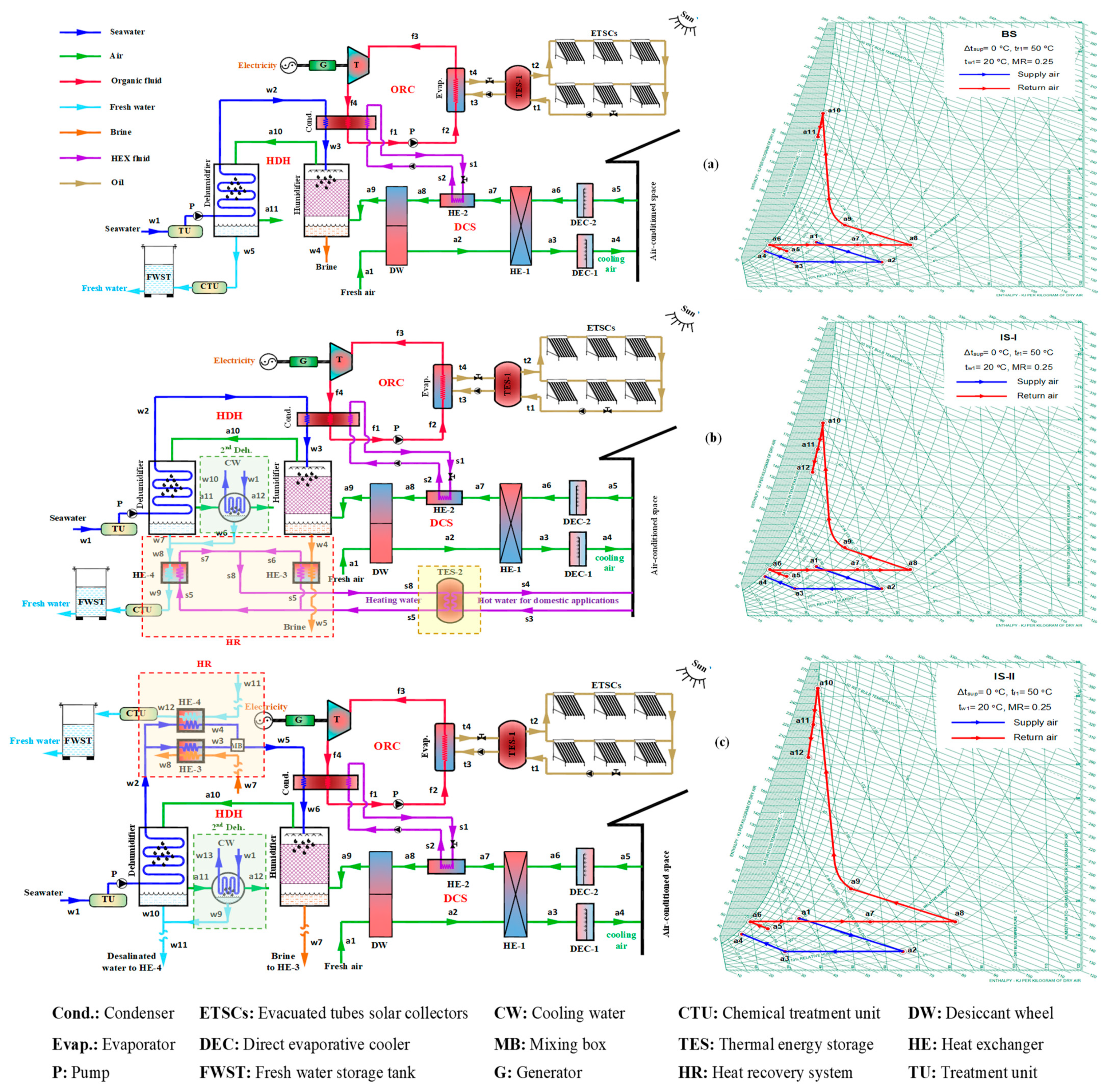
2. Systems Description

Three suggested solar-powered poly-generation systems are depicted in Figure 1, as illustrated by Almehmadi et al. [45]. Each system has a unique heat recuperation and energy storage unit. The suggested systems integrate solar ORC with DCS and an HDH desalination unit to offer energy, household heating and cooling, and fresh water. A solar collector made of evacuated tubes and a thermal storage reservoir is part of the system. For its size to maintain the liquid phase at temperatures up to 400 °C [46], Therminol-VP1 oil is employed as the operating fluid in the solar field loop. The proposed systems are the basic system (BS), which is used as a reference system; the improved system-I (IS-I); and the enhanced system-II (IS-II). The basic system (BS) can generate electricity, space cooling, and fresh water, as shown in Figure 1a. The system comprises four main cycles: two open cycles (water and air cycles) and two closed cycles (ORC and solar).
During the sunshine phased of the solar field cycle (state points t1 and t2), evacuated tube solar collectors fill the TES-1 tank and employed to provide the system with fixed energy via the ORC evaporator at all times of the day and night (state points t3 and t4). The ORC cycle’s evaporator transfers thermal oil heat to the ORC fluid, which is then evaporated and superheated (f3). Then, when the fluid has been enlarged in the turbine, it is sent to an electrical generator. Leaving the turbine at (f4), the ORC fluid is piped to the condenser (a three-fold channel heat exchanger), where it is cooled to (f1), and discarded heat is retrieved for the DCS and HDH units, maintaining a fixed temperature between state points (a8 and w3). Once the evaporator is full, the ORC liquid is pumped to (f2), and the cycle is complete.
At (a1), process air is taken into the desiccant wheel (DW), where it is warmed to (a2) and dehumidified; after exiting the DW, the air is cooled to (a1) in the HE-1 heat exchanger (a3). When the process air reaches the direct evaporative cooler (DEC-1), it is cooled and humidified at the a4 setting prior to being released into the conditioned area. After being cooled and humidified by the direct evaporative cooler (DEC-2), the air that has been sucked back into the conditioned room at (a5) is released outside at (a6). After the conditioned air returns, it is warmed-up via a heat exchanger (HE-1) (a7). After achieving the mandatory regeneration temperature (a8), the returned air (regeneration air) travels via a heat exchanger (HE-2) to regain some of the trash ORC condenser heat before being cooled and humidified in the reactivation section (DW) (a9). Finally, the HDH system’s humidifier constantly takes in the restoration air expelled by the DW, cooling and humidifying it (a10). It is then transported to the dehumidifier, where it undergoes dehumidification (a11). To better understand the air’s psychrometric cycle, refer to Figure 1a; the most elementary poly-generational system (BS) returned to the evaporator to finish the cycle.
Sea water at (w1) is pushed out of the water treatment unit (TU) to eliminate bacterial content, turbidity, and total dissolved solids that produce fouling and scaling in the tubes, resulting in desalinated water being generated in the water cycle (w5). To meet the World Health Organization’s (WHO) recommended salinity level of 500 parts per million (ppm), the desalinated water is processed via a chemical treatment unit (CTU). Information is then collected and archived in the FWST. After passing through a dehumidifier at a temperature of (w2), seawater is heated further by recovering some of the trash heat produced by an ORC condenser (w3). When the air from the DW of the DCS is dry, it is sent via a humidifier to make breathing more comfortable. Part of the purified water evaporates and is transferred to the dehumidifier by the entering air, whereas the remaining quantity is discharged as a brine at the hu-drain modifiers (w4).
Figure 1b illustrates the upgraded System-I (IS-I). The setup can produce power, air conditioning/heating, and potable water. It has the same components and working mechanism as the BS. Second-stage dehumidification, heat recovery, and a thermal energy storage unit are included to regain heat from brine (w4), and desalinated water is added to the system (w8). The suggested system (IS-I) is designed to deliver hot water for residential heating applications, a feature that makes it preferable to the baseline system (BS). At (a11) in IS-I, air passes from the first to second dehumidifier, where its relative humidity is reduced to a more manageable level (a12). The overall desalinated water yields at (w6) come from the combination of the desalinated water generated from the first step of dehumidification (w7) (w8). Then, TES-2 is utilized to recover most waste heat from desalinated water (w8) and brine water (w4) using a heat recovery system, yielding usable heating water for home uses. This contributes to the enhancement and smooth running of the system. Figure 1b also depicts the psychrometric cycle, which describes air actions via IS-I.
The improved system-II (IS-II) is presented in Figure 1c. The system can generate electricity, space cooling, and fresh water. This proposed system has the same components and operation as the (BS), including a second-stage dehumidifier and a heat recuperation system (HR). The proposed system (IS-II) is intended to recover heat from brine (w7) and desalinated water (w11) using an HR system to heat the supply seawater previously entering the humidifier (w2) to augment the humidification capacity of the HDH structure, which favors the planned system over the basic system (BS). In the IS-II, the seawater leaves the first-stage dehumidifier at point w2, where it is split into two streams to recuperate heat energy from desalinated water (w11) and brine (w7) by passing through HE-3 and HE-4 to (w5) (mixing of w3 and w4). Figure 1c depicts the psychrometric cycle of the air processed through the IS-II.
A comparison study between the proposed improved systems (IS-I and IS-II) is performed to identify the optimally performing system among the proposed systems.

3. Thermodynamics Analysis and Mathematical Modeling

Poly-generation systems envisaged for household applications have been explored and introduced using solar energy to desalinate water and provide air conditioning, electricity generation, and hot water. To compute the thermodynamic properties of subsystems and the performance of the whole system, the poly-generation system is split into ORC, DCS, and HDH. Throughout this phase of the simulation model, the first and second laws of thermodynamics are utilized in all parts of the system.
The following assumptions were made in the current model:
  • All processes inside the system run at a constant rate;
  • The system fails to account for air and water leaks in its components;
  • Energy from motion and gravity is ignored;
  • Wet-bulb air and blowdown water temperatures remain stable as they leave the humidifier;
  • There is no difference in the mass flow rate between process air, return air, and water.
  • At the outlet of the ORC condenser, the temperatures of the air (ta8) and the water (tw3) are the same;
  • HE-2 operates at full efficiency (ta8 = ts1);
  • At the turbine inlet, the ORC fluid is dry-saturated and superheated, depending on the values of tevap and the degree of superheating.
  • At the pump input, the ORC fluid is in a saturated liquid condition due to the condenser’s pressure;
  • The energy used by auxiliary components (such as fans) is not considered in the DCS and HDH systems;
  • n-Octane, an organic fluid with desirable performance and thermodynamic characteristics [47], is used for comparative investigation of the suggested systems; and
  • The related efficiencies of the elements of the systems were presented by Almehmadi et al. [48]. Table 1 presents the assumptions of the current study.
Productivity indicators in the investigated poly-generation systems include electrical power generation ( W n e t ), freshwater productivity ( m f r e s h ), space cooling capacity ( Q c o o l i n g ), and household heating capacity ( Q h e a t i n g ). The performance parameters of the system are specific total gained energy (STG), total gained output ratio (TGOR), specific total gained energy equivalent cost (STGP), gain output ratio (GORHDH), the thermal efficiency of the ORC (ηORC), DCS coefficient of performance (COPDCS), the conditioned space supply air temperature and humidity ratio (t4 and w4), and the area of the solar collectors (Asolar). In the current poly-generation system, electricity, space cooling capacity, fresh water, and warm water are all produced by solar energy simultaneously.

3.1. Organic Rankine Cycle (ORC)

In the interior, the constraint variety of the solar energy heat supply in the ORC system, the organic working fluid (n-Octane) is vaporized by applying solar energy due to its minimal boiling temperature and sufficient running pressure. In this section, we propose governing equations (Equations (1)–(11)) for the thermal efficiency of the evaporator, condenser, pump, turbine, and ORC established on the basis of the energy and mass balance:
Evaporator energy balance:
Q E v a p = m O R C ( h f 3 h f 2 )
m O R C ( h f 3 h f 2 ) = m o i l ( h t 3 h t 4 )
η s o l a r = Q E v a p I T , a v g , d a i l y A s o l a r
For this study, we set I T , a v g , d a i l y = 800   W / m 2 [17] as the daily average total solar strength, whereas the evacuated tube solar collector has a yearly average thermal efficiency of 63.2% [50,52].
Condenser energy balance
Q C o n d = m O R C ( h f 4 h f 1 )
ε c o n d = ( m W ( h w 3 h w 2 ) + m R , a ( h a 8 h a 7 ) m O R C ( h f 4 h f 1 ) )
M R = m O R C m R , a + m w
Turbine power
W t = m O R C ( h f 3 h f 4 ) η t η g
Pump power
W p = m O R C v f 1 ( P f 2 P f 1 ) / η p
W p = m O R C ( h f 2 , a h f 1 )
ORC net power and thermal efficacy
W n e t = W t W p
η O R C = W n e t Q E v a p

3.2. Desiccant Cooling System (DCS)

In the present investigation, we model the desiccant wheel, the heart of the DCS, utilizing the structure established by Panaras et al. [51]. Energy balances and controlling equations for the DCS components are presented below.
Desiccant wheel combined efficacy
F 1 , i = [ 2865 ( t i + 273.15 ) 1.49 ] + 4.344 [ w i / 1000 ] 0.8624
F 2 , i = [ ( t i + 273.15 ) 1.49 6360 ] 1.127 [ w i 1000 ] 0.07969
Desiccant wheel’s efficiency
η F 1 = F 1 , 2 F 1 , 1 F 1 , 8 F 1 , 1
η F 2 = F 2 , 2 F 2 , 1 F 2 , 8 F 2 , 1
The high-level efficiencies of the desiccant wheel are approximately η F 1 = 0.050 and η F 2 = 0.950 [53].
Desiccant wheel energy and mass balances
m P , a ( h a 2 h a 1 ) = m R , a ( h a 8 h a 9 )
m P , a ( w a 1 w a 2 ) = m R , a ( w a 9 w a 8 )
Heat exchanger
m P , a c p , m a ( t a 2 t a 3 ) = m R , a c p , m a ( t a 7 t a 6 )
ε H E 1 = m P , a c p , m a ( t a 2 t a 3 ) C m i n ( t a 2 t a 6 )
where C m i n = m i n { m P , a c p , m a , m R , a c p , m a } .
Direct evaporative coolers:
η D E C 1 = t a 3 t a 4 t a 3 t a 3 , w b
η D E C 1 = w a 4 w a 3 w a 4 , I d e a l w a 3
η D E C 2 = t a 5 t a 6 t a 5 t a 5 , w b
η D E C 2 = w a 6 w a 5 w a 6 , I d e a l w a 5
Regeneration energy, space cooling capacity, and coefficient of performance
Q i n , D C S = m R , a ( h a 8 h a 7 )
Q c o o l i n g = m P , a ( h a 5 h a 4 )
C O P D C S = Q c o o l i n g Q i n , D C S

3.3. Humidification–Dehumidification Water Desalination System (HDH)

The energy equilibrium of the humidifier is presented as:
m R , a ( h a 10 h a 9 ) = m w h w 3 m b r i n e h w 4 ( f o r   B S & I S I ) ,
m R , a ( h a 10 h a 9 ) = m w h w 6 m b r i n e h w 7 ( f o r   I S I I )
where
m b r i n e = m w m m a k e u p
The makeup water (sea or brackish water) mass flow rate that is offered to the system is expressed as
m m a k e u p = m R , a ( w a 10 w a 9 )
The primary dehumidifier in the energy balance and freshwater productivity are expressed as
m R , a ( h a 10 h a 11 ) = m w ( h w 2 h w 1 ) + m f r e s h h w 5
ε d e h 1 = m w c p , w ( t w 2 t w 1 ) c m i n ( t a 10 t w 1 )
m f r e s h ( B S ) = m R , a ( w a 10 w a 11 )
where
h w 5 = c p , w t a 11
C m i n = m i n { m w c p , w , m R , a c p , m a }
The energy balance, total freshwater productivity, and freshwater productivity of the second dehumidifier for the IS-I and IS-II systems are:
m R , a ( h a 11 h a 12 ) = m w ( h w 10 h w 1 ) + m f r e s h I I   h w 6
m f r e s h , I I = m R , a ( w a 11 w a 12 )
m f r e s h ( I S I   o r   I S I I ) = m f r e s h   ( B S ) + m f r e s h , I I
The gain output ratio (GOR) for the basic and IS-I and IS-II systems is expressed as
GOR HDH ( B S ) = m f r e s h   ( B S ) h f g m w ( h w 3 h w 2 ) + m R , a ( h a 9 h a 1 )
GOR HDH ( I S I ) = m f r e s h ( I S I ) h f g m w ( h w 3 h w 2 ) + m R , a ( h a 9 h a 11 )
GOR HDH ( I S I I ) = m f r e s h ( I S I I )   h f g m w ( h w 6 h w 2 ) + m R , a ( h a 9 h a 1 )

3.4. Hot Water for Domestic Application in IS-I

The energy balance of the HE-3 and HE-4 for system IS-I can be presented as
ε H E 3 = Q h e a t i n g I m b r i n e c p , w ( t w 4 t s 5 )
ε H E 4 = Q h e a t i n g I I m f r e s h ( I S I ) c p , w ( t w 8 t s 5 )
Q h e a t i n g = Q h e a t i n g I + Q h e a t i n g I I
m f r e s h ( I S I ) c p , w t w 8 = m f r e s h   ( B S ) c p , w t w 7 + m f r e s h , I I c p , w t w 6

3.5. Air and Water Waste Heat Recovery in IS-II

The energy balance of the HE-3 and HE-4 for system IS-II can be presented as
ε H E 3 = m w , 2 c p , w ( t w 3 t w 2 ) m b r i n e c p , w ( t w 7 t w 2 )
ε H E 4 = m w , 1 c p , w ( t w 4 t w 2 ) m f r e s h ( I S I I ) c p , w ( t w 11 t w 2 )
m w c p , w t w 5 = m w , 1 c p , w t w 4 + m w , 2 c p , w t w 3

3.6. System Performance Parameters and Evaluation

The tri-generation total gain ratio (TGOR), gained output ratio for independent systems (TGORind), STG, and STGP are as follows for the suggested basic, IS-I, and IS-II poly-generation systems.
TGOR BS = m f r e s h ( B S )   h f g + Q c o o l i n g + W n e t Q E v a p
TGOR IS I = m f r e s h ( I S I )   h f g + Q D o m e s + Q c o o l i n g + W n e t Q E v a p
TGOR IS II = m f r e s h ( I S I I ) h f g + Q c o o l i n g + W n e t Q E v a p
STG BS = ( m f r e s h ( B S )   h f g + Q c o o l i n g + W n e t ) Δ τ A S C
STG IS I = ( m f r e s h ( I S I )   h f g + Q h e a t i n g + Q c o o l i n g + W n e t ) Δ τ A S C
STG IS II = ( m f r e s h ( I S I I )   h f g + Q c o o l i n g + W n e t ) Δ τ A S C
STGP BS = [ m f r e s h ( B S ) × W U R + ( Q c o o l i n g + W n e t ) × E U R ] Δ τ
STGP IS I = [ m f r e s h ( I S I   o r   I S I I ) × W U R + ( Q D o m e s + Q c o o l i n g + W n e t ) × E U R ] Δ τ
STGP IS II = [ m f r e s h ( I S I I ) × W U R + ( Q c o o l i n g + W n e t ) × E U R ] Δ τ
where:
  • Δ τ : hours of daylight (12 h);
  • WUR: water unit rate USD/kg
  • EUR: Energy unit rate USD/kWh
Energy and freshwater costs can vary significantly across municipalities. In the current investigation, the average unit pricing for energy and water in Gulf cities [17,54] was used (USD 0.050/kWh and USD 2.50/m3, respectively).
The system’s governing equations (Equations (1)–(54)) were simulated utilizing C++ and EES software to determine the system’s performance and productivity characteristics under a variety of design and running circumstances, as shown in Table 1.

4. Results and Discussion

In this study, we evaluate the efficiency of three poly-generation systems (BS, IS-I, and IS-II) for residential and commercial buildings that couple solar ORC with district cooling and heating, high-efficiency heating, and hot water systems. In what follows, we report on the verification of the current model and how the suggested systems compare to existing, unrelated systems. Additionally, utilizing n-octane as an organic fluid, we examine, discuss, and evaluate the effects of the governing parameters (tsup, tf1, tw1, and MR) on the system’s productivity ( W ˙ n e t , m ˙ f r e s h , Q ˙ c o o l i n g , Q ˙ h e a t i n g ) and performance indicators (ORC, TGOR, GORHDH, STG, COPDCS, and STGP). Assessment parameters for the system are also supplied (ta4 and wa4).

4.1. Model Validation

We compared our most recent findings to those depicted in the literature to determine the level of correctness of the present thermodynamic models. Table 2 compares the thermodynamic models of the HDH, ORC, and DCS subsystems with data provided in [48,51,55,56]. As shown in Table 2, the results of this study are generally reliable in reference to those published in the literature.

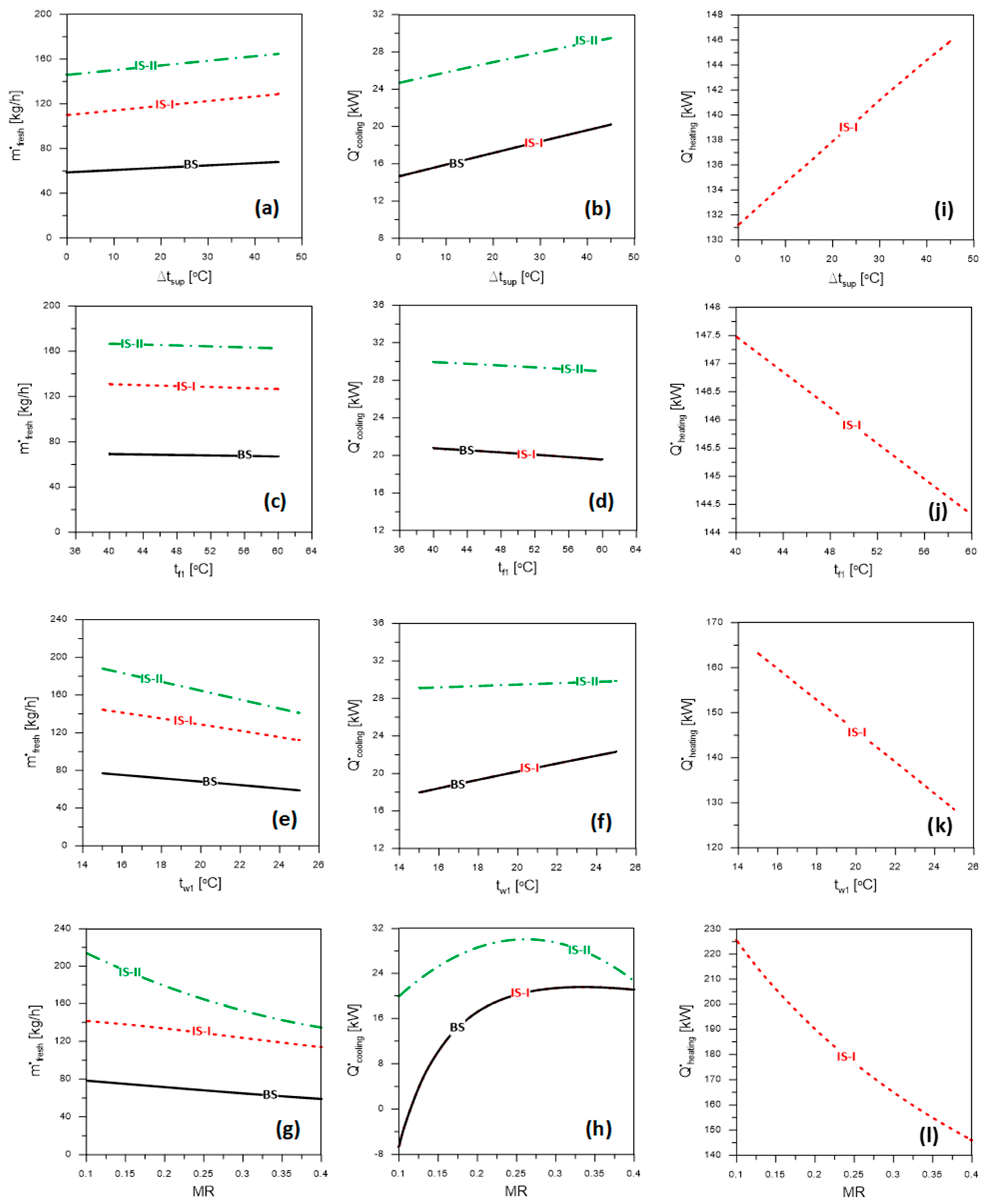
4.2. System Productivity

The effects of regulating parameters (Δtsup, tf1, tw1, and MR) on the system productivities ( m ˙ f r e s h , Q ˙ c o o l i n g ) of the indicated poly-generation systems (BS, IS-I, and IS-II) are illustrated in Figure 2 and (see Table 4 in Almehmadi et al. [48]). At tf1 = 50 °C, tw1 = 20 °C, and MR = 0.25, Figure 2a,b show the impact of the superheat degree (tsup) on the m ˙ f r e s h , Q ˙ c o o l i n g . As shown in Figure 2a,b, the values of m ˙ f r e s h , Q ˙ c o o l i n g improve as tsup rises. The three proposed systems all follow the same pattern. This is explained by the increased turbine work, the requirement for solar energy, and heat released in the ORC condenser when the temperature at the turbine inlet rises. This indicates the increase in the area required for the solar collectors, the humidifier’s capacity to humidify the air, and the capacity to cool the space.
Furthermore, the influence of tf1 on the system’s productivity is shown for Δtsup = 45 °C, tw1 = 20 °C, and MR = 0.25 in Figure 2c,d. The high condensing temperature of ORC is detrimental to W ˙ n e t , m ˙ f r e s h , Q ˙ c o o l i n g . This pattern appears with BS, as well as IS-I and IS-II. The enthalpy difference across the turbine is reduced as the condensation temperature is increased, decreasing the turbine power and the pace at which fresh water is produced because the quantity of water evaporation and therefore the dehumidifier capacity is decreased by limiting the heat regained from the condenser to the water and air flows before flowing into the humidifier. Additionally, lowering the regeneration temperature of DCS by raising the condenser pressure decreases the space cooling capacity.
In addition, Figure 2e,f demonstrates that an increase in tw1 has a negative impact on m ˙ f r e s h , a positive impact on Q ˙ c o o l i n g , and a negligible impact on W ˙ n e t at tsup = 45 °C, tf1 = 50 °C, and MR = 0.25. If the dehumidifier’s ability to remove moisture from the air is reduced, less fresh water is produced, resulting in a lower m ˙ f r e s h value. Because the fraction of saltwater heating energy regained from the ORC condenser decreases as the rest of the condenser’s heat is regained at a constant rate, an increase in DCS regeneration energy leads to an increased in Q ˙ c o o l i n g , whereas W ˙ n e t is unaffected by the rising water inlet temperature (see Table 4 in Almehmadi et al. [48]) because the ORC heat supply is decoupled from and free from the temperature of the saltwater input. The results of MR for m ˙ f r e s h , Q ˙ c o o l i n g , and W ˙ n e t are shown in Figure 2g,h for tsup = 45 °C, tf1 = 50 °C, and tw1 = 20 °C, respectively. As MR rises, the humidifier’s evaporation rate drops because less salt water is pumped through it. This has a negative effect on m ˙ f r e s h , reducing the quantity of usable fresh water. The graph in Figure 2h shows that when MR is increased, Q ˙ c o o l i n g rises to a maximum value and then begins to fall. The air flow rate decreases, and the enthalpy variation within the conditioned area increases when MR increases. During the first MR period, improved Q ˙ c o o l i n g is caused by an increase in enthalpy disparity throughout the space at the expense of a decrease in air mass flow rate and vice-versa during the second MR interval.
Comparing all suggested poly-generation systems, Figure 2a,c,e,g show that the fresh water productivity of the IS-II system is superior to that of the BS and IS-I systems. In contrast, the IS-I achieves superior performance to that of the BS system. The tendency is coherent through all Δtsup, tf1, tw1, and MR values. The rate of freshwater production of the IS-II system is superior to that of the IS-I system, which can be attributed to an improvement in the air humidification capacity through the humidifier, resulting from an increase in the seawater temperature due to the heat recovered from the saline and freshwater streams at HE-3 and HE-4, respectively. In other words, the higher the humidification capacity, the more fresh water obtained by the dehumidifier. The IS-I system produces more fresh water than the BS system because the IS-I system’s dehumidifier now has a second stage.
The conditioned space cooling of the intended systems is indicated in Figure 2b,d,f,h. The space cooling capacity of the IS-II system is greater than that of the BS and IS-I systems. Both the IS-I and BS systems exhibit space cooling capabilities at any tf1, tw1, Δtsup, or MR values. The Q ˙ c o o l i n g is improved in the IS-II system somewhat more than in IS-I system, which can be ascribed to an improvement in the DCS, which is a result of an increase in the heat recovered from the ORC condenser for DCS heat regeneration at HE-2. Additionally, the reduced heat recovered into the seawater stream at the same ORC heat liberation is due to the recovery of the waste heat in saline and fresh water at HE-3 and HE-4, respectively. Furthermore, the IS-I system generates Q ˙ c o o l i n g that is analogous to the BS system. Changes to the IS-I system have no impact on the DCS’s regeneration heat recovery (i.e., second-stage dehumidification, brine, and freshwater heat recovery at HE-3 and HE-4, respectively).
All three suggested poly-generation systems generate the same turbine power (see Table 4 in Almehmadi et al. [48]). The pattern holds, regardless of whether tsup, tf1, tw1, or MR is considered. Despite the significant enhancements of the IS-I and IS-II systems relative to the BS system, the turbine power remains unaffected (i.e., adding second-stage dehumidification, brine, and fresh water heat recovery).
Additionally, Figure 2i,j,k,l show the domestic heating productivity of system IS-I, which prevails compared with other systems (BS and IS-II), owing to recovery of the waste heat in brine and fresh water at HE-3 and HE-4, respectively. As shown in Figure 2i,j,k,l, the domestic heating capacity increases Δtsup and decreases tw1, tf1, and MR. The maximum W ˙ n e t , m ˙ f r e s h , and Q ˙ c o o l i n g within the ranges of all studied parameters are 102.0 kW (all systems), 214.0 kg/h (IS-II), and 29.94 kW (IS-II), respectively, which is a suitable productivity for small and moderate-scale buildings.

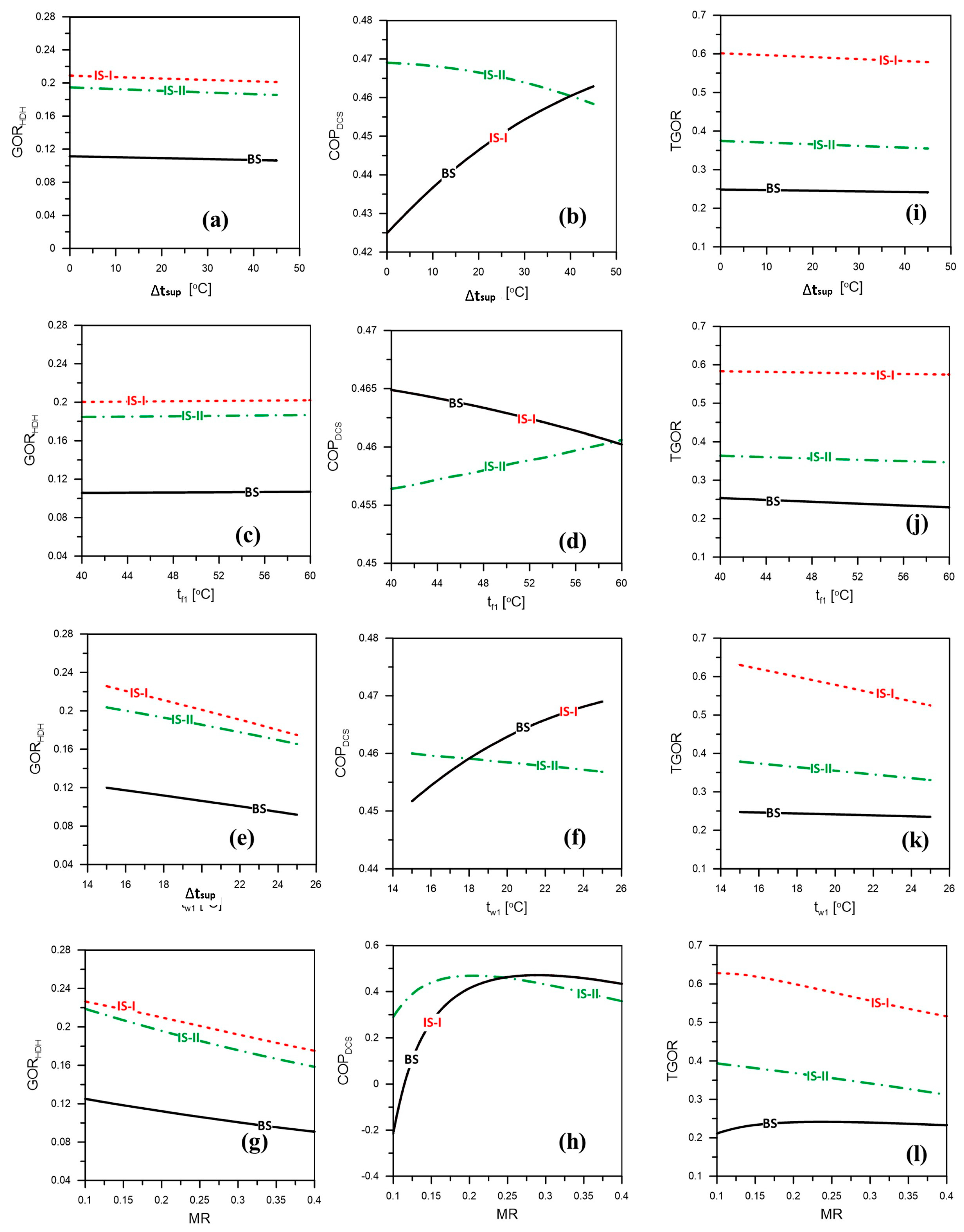
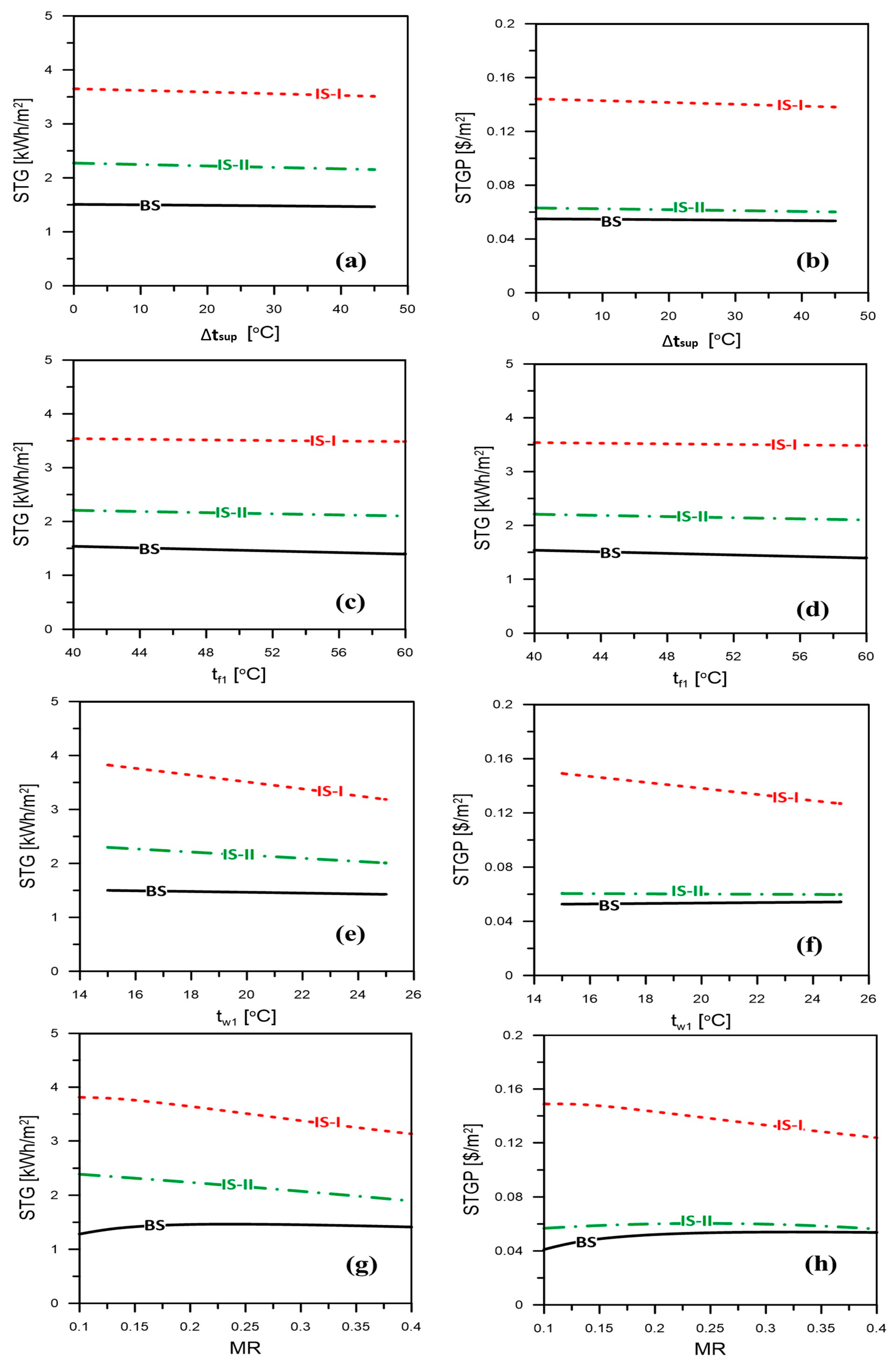
4.3. System Performance

Figure 3 and Figure 4 depict the effects of varying the regulating parameters (tsup, tw1, tf1, and MR) of the three proposed poly-generation systems (BS, IS-I, and IS-II) on the systems’ performance indicators (ORC, GORHDH, COPDCS, TGOR, STG, and STGP). As shown in the figures, the GORHDH, TGOR, STG, and STGP under operational conditions of tf1 = 50 °C, tw1 = 20 °C, and MR = 0.25 marginally decline with rising Δtsup. As the heat input to ORC, DCS, and HDH rises with rising turbine inlet temperature, a drop in GORHDH and ηORC occurs, with a consequent reduction in STGP, STG, and TGOR. Additionally, increasing the Δtsup has a constructive impact on the COPDCS of the BS and IS-I systems and an adverse impact on the COPDCS of IS-II system, as illustrated in Figure 3b. For all suggested systems, the solar area (Asolar) increased as Δtsup rises (see Table 4, Almehmadi et al. [48]). An increase in solar input heat to the ORC is necessary to increase the superheat at the turbine intake.
System performance characteristics (GORHDH, TGOR, STG, and STGP) for the IS-I system are superior to those of the BS and IS-II systems, as shown in Figure 3a,c and Figure 4a,b, comparing the three recommended poly-generation structures. In contrast, the IS-II system is superior to the BS system. The same pattern holds at any tsup. Increased total output system energy from recovered brine and fresh water ultimately leads to improved TGOR, STGP, and STG in the IS-I system as opposed to the IS-II system. As a result of this heat recovery, the heating capacity for residential purposes ( Q ˙ h e a t i n g ) is increased, enhancing the TGOR of IS-I rather than IS-II, as well as the STG and STGP. A comparison of the IS-I with IS-II shows that the GORHDH of the former is superior. For the IS-II system, the HDH system requires more input heat energy to produce the same amount of freshwater energy. Moreover, the IS-II system achieved better performance than the BS system for all system performance indicators, owing to the improvements that were added to it (i.e., adding second-stage dehumidification and saline and fresh water heat recovery at HE-3 and HE-4, respectively).
As depicted in Figure 3b, the COPDCS of the IS-II system is superior to that of the IS-I and BS systems, owing to the increasing heat energy that is regained for regeneration of DCS, which in turn increases Q ˙ c o o l i n g as explained in detail in Figure 2b. Furthermore, the COPDCS of the IS-I system is similar to that of the BS system. The IS-I and BS systems produce the same Q ˙ c o o l i n g for the same input heat energy (see explanations of Figure 2b).
Figure 3e,f and Figure 4c,d demonstrate the values of the system performance indicators ηORC, GORHDH, COPDCS (BS and IS-I), TGOR, STGP, and STG at running temperatures of Δtsup = 45 °C, tw1 = 20 °C, and MR = 0.250. With increased tf1, all performance indicators show a modest decline. The pattern is the same across all proposed schemes. As the condensation temperature increased, the enthalpy variation across the turbine decreases, causing a reduced overall efficiency of the cycle (ORC; see Table 4, Almehmadi et al. [48]). Increases in the input heat energy to HDH and DCS are responsible for the reductions in GORHDH, COPDCS (BS and IS-I), TGOR, STG, and STGP. When tf1 is raised, TGOR, STG, and STGP decrease. However, increasing COPDCS (IS-II) leads to a reduction in Q ˙ c o o l i n g , which cannot compensate for the decline in heat energy recovered for DCS heat regeneration entering the desiccant wheel, which in turn results in increased COPDCS. Solar area, (Asolar) declines with increased tf1 (see Table 4, Almehmadi et al. [48]) for the three suggested systems, owing to a reduction in the necessary solar input heat to the ORC with enhanced condensation temperature. The maximum TGOR, STG, and STGP within all explored factors are 0.63030 (IS-I), 3.8240 kWh/m2 (IS-I), and USD 0.1490/m2 (IS-I), respectively.
A comparison of the suggested poly-generation structures shows that the IS-I system performs better than the BS and IS-II systems. The IS-II system achieves better performance than that of the BS system. Furthermore, the COPDCS of the IS-I and BS systems is larger than that of the IS-II system, owing to the decline in heat energy that is recuperated from ORC for regeneration of DCS, which in turn reduces the Q ˙ c o o l i n g of IS-I and BS systems compared to IS-II (see Figure 2d). Furthermore, the COPDCS of the IS-I system is similar to that of the BS system, as both systems have the same Q ˙ c o o l i n g for the same input solar heat energy (see explanations of Figure 2d).
The impact of sea water temperature (tw1) on systems’ performance indicators is also displayed in Figure 3g–i and Figure 4e,f at Δtsup = 45 °C, tf1 = 50 °C, and MR = 0.25. As shown in the figures, the GORHDH, COPDCS (IS-II), TGOR, STGP, and STG decline as tw1 increased. Such a style is similar for all three planned systems. Figure 3 and Figure 4 show a decrease in GORHDH, COPDCS (IS-II), TGOR, STG, and STGP as tw1 increases. The improvement in COPDCS (BS and IS-I) is the result of the domination of the increased Q ˙ c o o l i n g over the DCS regeneration energy and vice-versa for system IS-II. The increase in the water inlet temperature does not influence the ηORC and Asolar (see Table 4, Almehmadi et al. [48]), owing to the independence of the solar heat supply of the ORC and the heat released to the sea water inlet temperature.
Likewise, Figure 3e–g,i demonstrate that the IS-I system achieves the best system performance among the three proposed systems inside the analyzed range of tw1. Moreover, the COPDCS of the IS-I and BS systems is superior to that of the IS-II system because the reduction in the heat energy recovered from ORC for regeneration of DCS overcomes the reduction in Q ˙ c o o l i n g of the IS-I and BS systems (see Figure 2f). For tw1 > 18 °C, such a trend appears. Furthermore, the COPDCS of the IS-I system is similar to that of the BS system, owing to the similar Q ˙ c o o l i n g generated by the IS-I and BS systems (refer to Figure 2d explanation).
At tsup = 45 °C, tf1 = 50 °C, and tw1 = 20 °C, Figure 3j–l and Figure 4g,h show the effects of MR mass flow rate proportion on the systems performance indicators. Across the board, most performance measures are reduced with increased MR in all three systems. Keeping the mass flow rates of air and saltwater constant, an increase in MR causes less evaporation in the humidifier and less condensation in the dehumidifier. GORHDH is reduced as a result, as seen in Figure 3j. Similarly, increasing MR causes COPDCS to increase slightly until it reaches its maximum, after which it falls off dramatically. The consequences of increasing MR are opposite (reduced air mass flow rate, reduced supply of air enthalpy to the conditioned space, and increasing enthalpy variation across the conditioned space). With increased Qcooling comes a decrease in air mass flow rate, leading to increased COPDCS (see the discussion in Figure 2h) and reduced TGOR. However, the increase in enthalpy difference throughout the conditioned region more than makes up for this. The ORC and Asolar also minimally respond to increases in MR (see Table 4, Almehmadi et al. [48]), indicating that the temperature of the saltwater entering the ORC is no longer reliant on the sun’s heat.
Figure 3j,l and Figure 4g,h demonstrate that the IS-I system achieves the best performance, and the BS system achieves the worst performance within the studied range of MR. Furthermore, for MR > 0.25, the COPDCS of the IS-I and BS systems is greater than that of the IS-II systems. However, the COPDCS of the IS-I system is similar to that of the BS system due to the same generated Qcooling (refer to Figure 2d explanation).
It can also be concluded from Figure 3b,e,h,k that the COPDCS of the IS-II system overperforms other systems (BS & IS-I) for Δtsup > 40 °C, tf1 > 59 °C, and tw1 > 18 °C and MR > 0.25.

4.4. System Selection, Evaluation, and Assessment

The selection and assessment of the planned systems is established on the basis of the number of required throughputs (electrical power, cooling/heating capacity, and fresh water) and overall performance (TGOR). Accordingly, the system with the highest TGOR does not need to produce more electrical power, cooling and/or heating capacity, and fresh water than the other systems. Therefore, the choice of the system depends on the type and amount of productivity necessary, in addition to considering the TGOR for energy-saving considerations, if any.
Figure 5a–f compares all proposed systems (BS, IS-I, and IS-II) at the maximum system productivity and performance parameters under the same operational circumstances.
The maximum W ˙ n e t , m ˙ f r e s h , and Q ˙ c o o l i n g within the ranges of all examined parameters are 102.0 kW (all systems), 214.0 kg/h (IS-II), and 29.940 kW (IS-II), respectively. The maximum TGOR, STG, and STGP within the ranges of all analyzed parameters are 0.6303 (IS-I), 3.8239 kWh/m2 (IS-I), and USD 0.1490/m2 (IS-I). System performance evaluation for the proposed systems can be expressed by TGOR, ta4, and wa4.
The GORHDH, TGOR, STG, and STGP values for the IS-I system are greater than those for the BS and IS-II systems, as the STG and STGP values for the IS-I are greater than those of the BS system. The IS-I and BS systems have lower COPDCS values than the IS-II system has. Additionally, the IS-I system features superior performance indicators than the BS system. The COPDCS values of the IS-I and BS systems are more than that of the IS-II system when the MR is greater than 0.25.
Space-supplied air conditions (ta4 and wa4) are used to ensure human comfort within the conditioned space and may also be used as a metric for the assessment of systems. Figure 6a shows the psychrometric charts for the BS and IS-I systems at 25 °C and 12 gv/kga. Figure 6b shows the psychrometric charts for the IS-II system under the same circumstances (Figure 6b). The figures demonstrate that for systems BS and IS-I, the approved conditions of space-supplied air are ta4 = 15.50–18.20 °C and wa4 = 9.20–12.0 gv/kga, whereas for the IS-II system, these values are ta4 = 14.9–18.3 °C and wa4 = 8.5–12.0 gv/kga. Otherwise, the conditions outside are not desirable. The accepted conditions are determined based on the following assumptions according to ASHRAE recommendations: (i) the supply air conditions (temperature and specific humidity) should be lower than the standard room comfort condition (temperature (25 °C), specific humidity (12 g/kg), and relative humidity (50%); and (ii) the room sensible heat factor in the summer season should be less than or equal to one (RSHF ≤ 1).
Figure 7a,b show the boundaries of conditioned space conditions (wa4 and ta4) for the three planned systems (BS, IS-I, and IS-II) at any W ˙ n e t and m ˙ f r e s h for all studied parameter ranges. Moreover, Figure 7c demonstrates the quantities and constraints of W ˙ n e t and Q ˙ c o o l i n g at every m ˙ f r e s h value used for all systems and explored parameter varieties. Figure 7 may assist researchers, power plant designers, solar poly-generation developers, and stakeholders in the design stage with respect to the planned system productivity (electricity, space cooling, fresh water) to select the appropriate poly-generation system depending on the required application.

4.5. Comparisons with Previous Related Systems

We evaluated our findings in comparison with incorporated systems in the literature to demonstrate the capacity, dependability, adaptability, and functional application of the proposed systems. Cogeneration and trigeneration techniques for the production of cooling, heating, electricity, and fresh water that are equivalent to the proposed systems are chosen from the literature. However, as indicated in Table 3, their operating circumstances differ from our specified settings. The extreme TGOR and highest freshwater productivity are used as performance and productivity measures for assessment. As demonstrated in Table 3, the highest TGOR of the proposed system (IS-I) does not substantially differ from that of similar systems. It is greater than that in [57,58] and closer to [59,60] but lower than [38,61,62]. Furthermore, the existing system’s maximum water productivity (IS-II) is greater than that reported in [16,17,34] but lower than [54,63]. The disparities can be attributed to similar system operating circumstances, type, configuration, and prime mover variances.

5. Conclusions and Recommendations

To generate electricity, fresh water, and space cooling/domestic heating for small and moderately sized buildings, theoretical investigations of three distinct and innovative solar-motivated poly-generation systems (BS, IS-I, and IS-II) combined with DCS, ORC, and HDH with other heat recovery structures were conducted. Productivity and performance indicators were studied to determine how they were affected by varying operational and design characteristics. The following are some of the most important conclusions that can serve as recommendations for final product design:
  • With the suggested poly-generation systems, small and medium-sized buildings may generate their power, fresh water, and cooling/domestic heating while still providing a comfortable environment for their occupants.
  • W ˙ n e t , m ˙ f r e s h , and Q ˙ c o o l i n g all increase with tsup and are reduced with ORC condensing temperature, whereas tw1 has a negative impact on m ˙ f r e s h , a positive impact on Q ˙ c o o l i n g , and a negligible impact on W ˙ n e t .
  • Mass flow rate ratio (MR) has adverse effects on m ˙ f r e s h and a positive effect on Q ˙ c o o l i n g until it reaches a maximum value at MR = 0.25, then reduces with increased MR.
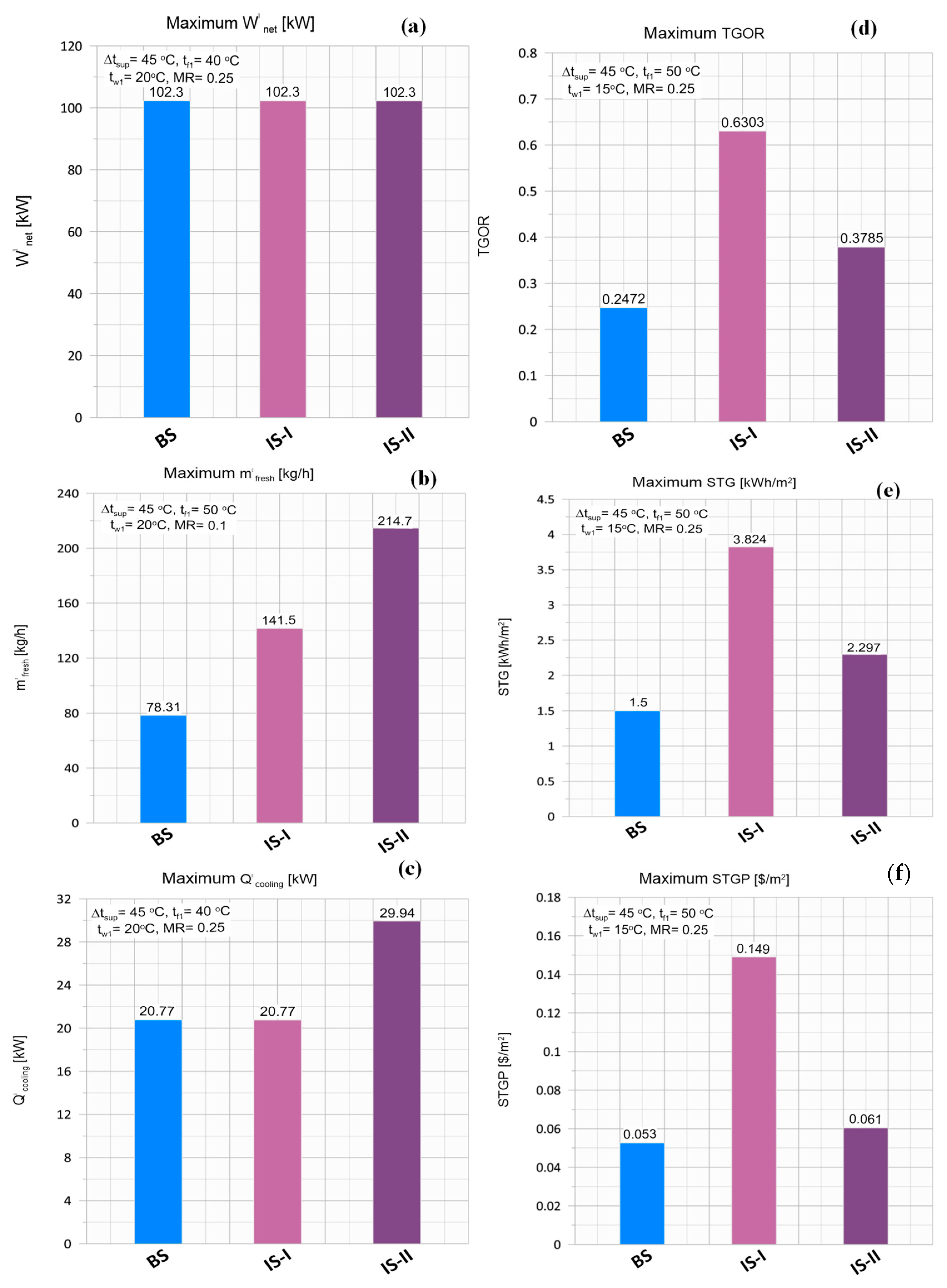
  • The IS-II system exhibits a higher freshwater productivity and space cooling capacity that the other systems (BS and IS-I).
  • The GORHDH, TGOR, STG, and STGP values for the IS-I system are greater than those of the BS and IS-II systems, whereas the STG and STGP values for the IS-I system are higher than those of the BS system.
  • Seawater inlet temperature adversely affects GORHDH, COPDCS (IS-II), TGOR, STG, and STGP for all systems.
  • COPDCS, TGOR, STGP, and STG increase with increased MR until they reach the highest values at MR = 0.25, then decrease considerably.
  • For MR > 0.25, the COPDCS of the IS-I and BS systems is higher than that of the IS-II system.
  • The maximum W ˙ n e t , m ˙ f r e s h , and Q ˙ c o o l i n g within the ranges of all studied parameters are 102.0 kW (all systems), 214.0 kg/h (IS-II), and 29.94 kW (IS-II), respectively.
  • The maximum TGOR, STG, and STGP within the varieties of all studied parameters are 0.6303 (IS-I), 3.8239 kWh/m2 (IS-I), and USD 0.1490/m2 (IS-I), respectively.
  • In conclusion, future research on poly-generation systems should focus on enhancing ORC to power various air conditioning (absorption and adsorption) and desalination (RO and MED) systems.

Author Contributions

Conceptualization, S.A., H.F.E., A.F., F.A.A., M.A.A., J.M. and H.A.R.; Data curation, H.F.E.; Formal analysis, H.F.E., A.F. and H.A.R.; Funding acquisition, S.A.; Investigation, H.F.E.; Methodology, H.F.E. and A.F.; Project administration, S.A.; Software, A.F. and S.A.; Supervision, F.A.A., J.M. and M.A.A.; Validation, H.F.E. and A.F.; Visualization, H.A.R.; Writing—original draft, H.F.E., A.F., J.M. and H.A.R.; Writing—review and editing, F.A.A., S.A., J.M., M.A.A. and H.A.R. All authors have read and agreed to the published version of the manuscript.

Funding

This research was funded by Deanship of Scientific Research under project number (NU/RG/SERC/11/9), Najran University, Najran, Saudi Arabia.

Acknowledgments

The authors are thankful to the Deanship of Scientific Research at Najran University for funding this work under the Research Groups Funding Program (grant code (NU/RG/SERC/11/9)).

Conflicts of Interest

The authors declare no conflict of interest.

Nomenclature

AArea, m2
CpSpecific heat, kJ/kg K
F1, F2Combined potential
hfgWater latent heat of evaporation, kJ/kg
hSpecific enthalpy, kJ/kg
QRate of heat transfer, kW
tTemperature, °C
WHumidity ratio, gv/kga
Subscript
aAir/dry air/actual
atmAtmosphere
avgAverage
gGenerator
humHumidifier
i = 1,2,3Index referring to numerous locations of the desiccant system
impImprovement
inInput
indIndependent
maMoist air
vWater vapor
regRegeneration
R,aReturn air
P,aProcess air
PPump
tTurbine
wSeawater
1, 2, 3, …State points
Abbreviations
ROReverse osmosis
SOFC Solid oxide fuel cell
STGSpecific total gained energy, kWh/m2

References

  1. Mehrpooya, M.; Sharifzadeh, M.M.M.; Rosen, M.A. Energy and exergy analyses of a novel power cycle using the cold of LNG (liquefied natural gas) and low-temperature solar energy. Energy 2016, 95, 324–345. [Google Scholar] [CrossRef]
  2. Karellas, S.; Braimakis, K. Energy—Exergy analysis and economic investigation of a cogeneration and trigeneration ORC–VCC hybrid system utilizing biomass fuel and solar power. Energy Convers. Manag. 2016, 107, 103–113. [Google Scholar] [CrossRef]
  3. Sahoo, U.; Kumar, R.; Pant, P.C.; Chaudhury, R. Scope and sustainability of hybrid solarebiomass power plant with cooling, desalination in polygeneration process in India. Renew. Sustain. Energy Rev. 2015, 51, 304–316. [Google Scholar] [CrossRef]
  4. Irshad, K.; Zahir, M.H.; Shaik, M.S.; Ali, A. Buildings’ Heating and Cooling Load Prediction for Hot Arid Climates: A Novel Intelligent Data-Driven Approach. Buildings 2022, 12, 1677. [Google Scholar] [CrossRef]
  5. Mustafa, J.; Husain, S.; Alqaed, S.; Khan, U.A.; Jamil, B. Performance of Two Variable Machine Learning Models to Forecast Monthly Mean Diffuse Solar Radiation across India under Various Climate Zones. Energies 2022, 15, 7851. [Google Scholar] [CrossRef]
  6. Das, L.; Aslfattahi, N.; Habib, K.; Saidur, R.; Irshad, K.; Yahya, S.M.; Kadirgama, K. Improved Thermophysical Characteristics of a New Class of Ionic Liquid + Diethylene Glycol/Al2O3 + CuO Based Ionanofluid as a Coolant Media for Hybrid PV/T System. Therm. Sci. Eng. Prog. 2022, 36, 101518. [Google Scholar] [CrossRef]
  7. Khaliq, A.; Refaey, H.; Alharthi, M.A. Development and analysis of a novel CSP source driven cogeneration cycle for the production of electric power and low temperature refrigeration. Int. J. Refrig. 2021, 130, 330–346. [Google Scholar] [CrossRef]
  8. Chen, Q.; Xu, J.; Chen, H. A New Design Method for Organic Rankine Cycles with Constraint of Inlet and Outlet Heat Carrier Fluid Temperatures Coupling with the Heat Source. Appl. Energy 2012, 98, 562–573. [Google Scholar] [CrossRef]
  9. Mahmoudi, S.M.S. Utilization of Waste Heat from GT-MHR for Power Generation in Organic Rankine Cycles. Appl. Therm. Eng. 2010, 30, 366–375. [Google Scholar] [CrossRef]
  10. Habka, M.; Ajib, S. Evaluation of Mixtures Performances in Organic Rankine Cycle When Utilizing the Geothermal Water with and without Cogeneration. Appl. Energy 2015, 154, 567–576. [Google Scholar] [CrossRef]
  11. Kumar, R.; Shukla, A.K.; Sharma, M.; Nandan, G. Thermodynamic investigation of water generating system through HDH desalination and RO powered by organic Rankine cycle. Mater. Today 2021, 46, 5256–5261. [Google Scholar] [CrossRef]
  12. Yari, M.; Ariyanfar, L.; Aghdam, E.A. Analysis and performance assessment of a novel ORC based multigeneration system for power, distilled water and heat. Renew. Energy 2018, 119, 262–281. [Google Scholar]
  13. He, W.F.; Han, D.; Xu, L.N.; Yue, C.; Pu, W.H. Performance Investigation of a Novel Water–Power Cogeneration Plant (WPCP) Based on Humidification Dehumidification (HDH) Method. Energy Convers. Manag. 2016, 110, 184–191. [Google Scholar] [CrossRef]
  14. El-Agouz; Sathyamurthy, R.; Manokar, M. Improvement of Humidification–Dehumidification Desalination Unit Using a Desiccant Wheel. Chem. Eng. Res. Des. 2018, 131, 104–116. [Google Scholar] [CrossRef]
  15. Abdelgaied, M.; Kabeel, A.E.; Zakaria, Y. Performance Improvement of Desiccant Air Conditioner Coupled with Humidification-Dehumidification Desalination Unit Using Solar Reheating of Regeneration Air. Energy Convers. Manag. 2019, 198, 111808. [Google Scholar] [CrossRef]
  16. Nada, S.; Fouda, A.; Mahmoud, M.; Elattar, H. Experimental investigation of air-conditioning and HDH desalination hybrid system using new packing pad humidifier and strips-finned helical coil. Appl. Therm. Eng. 2021, 185, 116433. [Google Scholar] [CrossRef]
  17. Fouda, A.; Nada, S.; Elattar, H. An integrated A/C and HDH water desalination system assisted by solar energy: Transient analysis and economical study. Appl. Therm. Eng. 2016, 108, 1320–1335. [Google Scholar] [CrossRef]
  18. Elattar, H.F.; Nada, S.A.; Al-Zahrani, A.; Fouda, A. Humidification-dehumidification water desalination system integrated with multiple evaporators/condensers heat pump unit. Int. J. Energy Res. 2020, 44, 6396–6416. [Google Scholar] [CrossRef]
  19. Wang, J.; Wu, J.; Zheng, C. Analysis of Tri-Generation System in Combined Cooling and Heating Mode. Energy Build. 2014, 72, 353–360. [Google Scholar] [CrossRef]
  20. Ahmadi, P.; Dincer, I.; Rosen, M.A. Performance Assessment and Optimization of a Novel Integrated Multigeneration System for Residential Buildings. Energy Build. 2013, 67, 568–578. [Google Scholar] [CrossRef]
  21. Mohammadi, S.M.H.; Ameri, M. Energy and Exergy Analysis of a Tri-Generation Water-Cooled Air Conditioning System. Energy Build. 2013, 67, 453–462. [Google Scholar] [CrossRef]
  22. Liu, H.; Zhou, Q.; Zhao, H.; Wang, P. Experiments and thermal modeling on hybrid energy supply system of gas engine heat pumps and organic Rankine cycle. Energy Build. 2015, 87, 226–232. [Google Scholar] [CrossRef]
  23. Sibilio, S.; Rosato, A.; Ciampi, G.; Scorpio, M.; Akisawa, A. Building-integrated trigeneration system: Energy, environmental and economic dynamic performance assessment for Italian residential applications. Renew. Sustain. Energy Rev. 2017, 68, 920–933. [Google Scholar] [CrossRef]
  24. Jradi, M.; Riffat, S. Tri-generation systems: Energy policies, prime movers, cooling technologies, configurations and operation strategies. Renew. Sustain. Energy Rev. 2014, 32, 396–415. [Google Scholar] [CrossRef]
  25. Leonzio, G. An innovative trigeneration system using biogas as renewable energy. Chin. J. Chem. Eng. 2018, 26, 1179–1191. [Google Scholar] [CrossRef]
  26. Zhang, X.; Li, H.; Liu, L.; Zeng, R.; Zhang, G. Analysis of a feasible trigeneration system taking solar energy and biomass as co-feeds. Energy Convers. Manag. 2016, 122, 74–84. [Google Scholar] [CrossRef]
  27. Maraver, D.; Uche, J.; Royo, J. Assessment of high temperature organic Rankine cycle engine for polygeneration with MED desalination: A preliminary approach. Energy Convers. Manag. 2012, 53, 108–117. [Google Scholar] [CrossRef]
  28. Islam, S.; Dincer, I.; Yilbas, B.S. Development, analysis and assessment of solar energy based multigeneration system with thermoelectric generator. Energy Convers. Manag. 2018, 156, 746–756. [Google Scholar] [CrossRef]
  29. Calise, F.; d’Accadia, M.D.; Macaluso, A.; Piacentino, A.; Vanoli, L. Exergetic and exergoeconomic analysis of a novel hybrid solar–geothermal polygeneration system producing energy and water. Energy Convers. Manag. 2016, 115, 200–220. [Google Scholar] [CrossRef]
  30. Zare, V. A comparative thermodynamic analysis of two tri-generation systems utilizing low-grade geothermal energy. Energy Convers. Manag. 2016, 118, 264–274. [Google Scholar] [CrossRef]
  31. Azhar, M.S.; Rizvi, G.; Dincer, I. Integration of renewable energy based multigeneration system with desalination. Desalination 2017, 404, 72–78. [Google Scholar] [CrossRef]
  32. Ghorbani, B.; Mehrpooya, M.; Sadeghzadeh, M. Developing a Tri-Generation System of Power, Heating, and Freshwater (for an Industrial Town) by Using Solar Flat Plate Collectors, Multi-Stage Desalination Unit, and Kalina Power Generation Cycle. Energy Convers. Manag. 2018, 165, 113–126. [Google Scholar] [CrossRef]
  33. Baghernejad, A.; Yaghoubi, M.; Jafarpur, K. Exergoeconomic Comparison of Three Novel Trigeneration Systems Using SOFC, Biomass and Solar Energies. Appl. Therm. Eng. 2016, 104, 534–555. [Google Scholar] [CrossRef]
  34. Abdelhay, A.; Fath, H.S.; Nada, S.A. Solar driven polygeneration system for power, desalination and cooling. Energy 2020, 198, 117341. [Google Scholar] [CrossRef]
  35. Dabwan, Y.N.; Pei, G.; Gao, G.; Feng, J.; Li, J. A Novel Integrated Solar Tri-Generation System for Cooling, Freshwater and Electricity Production Purpose: Energy, Economic and Environmental Performance Analysis. Sol. Energy 2020, 198, 139–150. [Google Scholar] [CrossRef]
  36. Yao, E.; Wang, H.; Wang, L.; Xi, G.; Maréchal, F. Multi-Objective Optimization and Exergoeconomic Analysis of a Combined Cooling, Heating and Power Based Compressed Air Energy Storage System. Energy Convers. Manag. 2017, 138, 199–209. [Google Scholar] [CrossRef]
  37. Gholizadeh, T.; Vajdi, M.; Rostamzadeh, H. A New Trigeneration System for Power, Cooling, and Freshwater Production Driven by a Flash-Binary Geothermal Heat Source. Renew. Energy 2020, 148, 31–43. [Google Scholar] [CrossRef]
  38. Bellos, E.; Tzivanidis, C. Multi-Objective Optimization of a Solar Driven Trigeneration System. Energy 2018, 149, 47–62. [Google Scholar] [CrossRef]
  39. Gholizadeh, T.; Vajdi, M.; Rostamzadeh, H. Exergoeconomic optimization of a new trigeneration system driven by biogas for power, cooling, and freshwater production. Energy Convers. Manag. 2020, 205, 112417. [Google Scholar] [CrossRef]
  40. Ghorab, M.; Yang, L.; Entchev, E.; Lee, E.-J.; Kang, E.-C.; Kim, Y.-J.; Bae, S.; Nam, Y.; Kim, K. Multi-objective optimization of hybrid renewable Tri-generation system performance for buildings. Appl. Sci. 2022, 12, 888. [Google Scholar] [CrossRef]
  41. Li, J.; Zoghi, M.; Zhao, L. Thermo-economic assessment and optimization of a geothermal-driven tri-generation system for power, cooling, and hydrogen production. Energy 2022, 244, 123151. [Google Scholar] [CrossRef]
  42. Fouda, A.; Nada, S.; Elattar, H.; Rubaiee, S.; Al-Zahrani, A. Performance analysis of proposed solar HDH water desalination systems for hot and humid climate cities. Appl. Therm. Eng. 2018, 144, 81–95. [Google Scholar] [CrossRef]
  43. Dincer, I.; Demir, M.E. Steam and Organic Rankine Cycles. Compr. Energy Syst. 2018, 4, 264–311. [Google Scholar]
  44. Fouda, A.; Elattar, H.F.; Rubaiee, S.; Bin Mahfouz, A.S.; Alharbi, A.M. Thermodynamic and Performance Assessment of an Innovative Solar-Assisted Tri-Generation System for Water Desalination, Air-Conditioning, and Power Generation. Eng. Technol. Appl. Sci. Res. 2022, 12, 9316–9328. [Google Scholar] [CrossRef]
  45. Almehmadi, F.A.; Elattar, H.F.; Fouda, A.; Alqaed, S.; Mustafa, J.; Alharthi, M.A.; Refaey, H.A. Energy Performance Assessment of a Novel Solar Poly-Generation System Using Various ORC Working Fluids in Residential Buildings. Energies 2022, 15, 8286. [Google Scholar] [CrossRef]
  46. Eldean, M.A.S.; Soliman, A.M. Study of using solar thermal power for the margarine melting heat process. J. Sol. Energy Eng. 2015, 137, 210041–2100413. [Google Scholar] [CrossRef] [Green Version]
  47. Walraven, D.; Laenen, B.; D’Haeseleer, W. Comparison of thermodynamic cycles for power production from low-temperature geothermal heat sources. Energy Convers. Manag. 2013, 66, 220–233. [Google Scholar] [CrossRef] [Green Version]
  48. Almehmadi, F.A.; Elattar, H.F.; Fouda, A.; Alqaed, S.; Alharthi, M.A.; Refaey, H.A. Towards an Efficient Multi-Generation System Providing Power, Cooling, Heating, and Freshwater for Residential Buildings Operated with Solar-Driven ORC. Appl. Sci. 2022, 12, 11157. [Google Scholar] [CrossRef]
  49. Zhang, T.; Ma, J.; Zhou, Y.; Wang, Y.; Chen, Q.; Li, X.; Liu, L. Thermo-Economic Analysis and Optimization of ICE-ORC Systems Based on a Splitter Regulation. Energy 2021, 226, 120271. [Google Scholar] [CrossRef]
  50. Ayompe, L.M.; Duffy, A. Thermal Performance Analysis of a Solar Water Heating System with Heat Pipe Evacuated Tube Collector Using Data from a Field Trial. Sol. Energy 2013, 90, 17–28. [Google Scholar] [CrossRef] [Green Version]
  51. Panaras, G.; Mathioulakis, E.; Belessiotis, V.; Kyriakis, N. Theoretical and experimental investigation of the performance of a desiccant air-conditioning system. Renew. Energy 2010, 35, 1368–1375. [Google Scholar] [CrossRef]
  52. Mekhilef, S.; Saidur, R.; Safari, A. A Review on Solar Energy Use in Industries. Renew. Sustain. Energy Rev. 2011, 15, 1777–1790. [Google Scholar] [CrossRef]
  53. Wang, N.; Wang, D.; Dong, J.; Wang, H.; Wang, R.; Shao, L.; Zhu, Y. Performance assessment of PCM-based solar energy assisted desiccant air conditioning system combined with a humidification-dehumidification desalination unit. Desalination 2020, 496, 114705. [Google Scholar] [CrossRef]
  54. Nada, S.A.; Elattar, H.F.; Fouda, A. Performance Analysis of Proposed Hybrid Air Conditioning and Humidification–Dehumidification Systems for Energy Saving and Water Production in Hot and Dry Climatic Regions. Energy Convers. Manag. 2015, 96, 208–227. [Google Scholar] [CrossRef]
  55. Zubair, S.M.; Antar, M.A.; Elmutasim, S.; Lawal, D.U. Performance evaluation of humidification-dehumidification (HDH) desalination systems with and without heat recovery options: An experimental and theoretical investigation. Desalination 2018, 436, 161–175. [Google Scholar] [CrossRef]
  56. Galloni, E.; Fontana, G.; Staccone, S. Design and experimental analysis of a mini ORC (organic Rankine cycle) power plant based on R245fa working fluid. Energy 2015, 90, 768–775. [Google Scholar] [CrossRef]
  57. Al-Sulaiman, F.A.; Dincer, I.; Hamdullahpur, F. Energy analysis of a trigeneration plant based on solid oxide fuel cell and organic Rankine cycle. Int. J. Hydrogen Energy 2010, 35, 5104–5113. [Google Scholar] [CrossRef]
  58. Huang, Y.; Wang, Y.; Rezvani, S.; McIlveen-Wright, D.; Anderson, M.; Mondol, J.; Zacharopolous, A.; Hewitt, N. A techno-economic assessment of biomass fuelled trigeneration system integrated with organic Rankine cycle. Appl. Therm. Eng. 2013, 53, 325–331. [Google Scholar] [CrossRef]
  59. Puig-Arnavat, M.; Bruno, J.C.; Coronas, A. Modeling of trigeneration configurations based on biomass gasification and comparison of performance. Appl. Energy 2014, 114, 845–856. [Google Scholar] [CrossRef]
  60. Elattar, H.F.; Fouda, A.; Nada, S.A. Performance Investigation of a Novel Solar Hybrid Air Conditioning and Humidification–Dehumidification Water Desalination System. Desalination 2016, 382, 28–42. [Google Scholar] [CrossRef]
  61. Choi, J.H.; Ahn, J.H.; Kim, T.S. Performance of a triple power generation cycle combining gas/steam turbine combined cycle and solid oxide fuel cell and the influence of carbon capture. Appl. Therm. Eng. 2014, 71, 301–309. [Google Scholar] [CrossRef]
  62. Chen, Y.; Zhao, D.; Xu, J.; Wang, J.; Lund, P.D. Performance analysis and exergo-economic optimization of a solar-driven adjustable tri-generation system. Energy Convers. Manag. 2021, 233, 113873. [Google Scholar] [CrossRef]
  63. Lian, Z.; Chua, K.; Chou, S. A thermoeconomic analysis of biomass energy for trigeneration. Appl. Energy 2010, 87, 84–95. [Google Scholar] [CrossRef]
Figure 1. Schematic diagrams and psychrometric cycles of the proposed poly-generation systems: (a) the basic system (BS), (b) the improved system-I (IS-I), and (c) the improved system-II (IS-II) [45].
Energies 15 08750 g001
Figure 2. Impact of examined parameters on the productivities of the suggested systems: (ag) m ˙ f r e s h ; (bh) Q ˙ c o o l i n g ; (il) Q ˙ h e a t i n g .
Energies 15 08750 g002
Figure 3. Impact of examined parameters on the performance indicators of the proposed systems: (aj) GORHDH; (bk) COPDCS; (cl) TGOR.
Energies 15 08750 g003
Figure 4. Impact of analyzed parameters on the STG and STG of the suggested systems: (a,b) effect of Δtsup; (c,d) effect of tf1; (e,f) effect of tw1; (g,h) effect of MR.
Energies 15 08750 g004
Figure 5. Assessments of maximum suggested system productivity and performance indicators: (a) W ˙ n e t ; (b) m ˙ f r e s h ; (c) Q ˙ c o o l i n g ; (d) TGOR; (e); STG; (f) STGP.
Energies 15 08750 g005
Figure 6. Accepted provided conditions for air-conditioned space (systems assessment): (a) BS and IS-I, (b) IS-II.
Energies 15 08750 g006
Figure 7. Analysis and evaluation of the system’s (a) power output and space cooling capability vs. produced freshwater rate, (b) supplied-air conditions versus output power, and (c) space cooling capacity and power output versus generated freshwater rate.
Energies 15 08750 g007
Table 1. The assumptions, values, and ranges of the present study.
Assumptions
Pump efficiency of ORC, ηpump [49]0.85
Turbine efficiency of ORC, ηturbine [49]0.85
Evacuated tube solar collector efficiency, ηsolar [50]0.6320
ORC electrical generator efficiency, ηg [49]0.95
Desiccant wheel efficiency, ηF1 [49,51]0.05
Desiccant wheel efficiency, ηF2 [49,51]0.95
Evaporative cooler-1 efficiency, ηDEC-1 [49,51]0.90
Evaporative cooler-2 efficiency, ηDEC-2 [49,51]0.90
Heat exchanger effeciencies, ηHE-1, ηHE-2, ηHE-3, and ηHE-4 [49,51]0.80
Dehumidifier efficiency, ηDh [17].0.95
Table 2. Validation of the current model against available HDH, DCS, and ORC systems.
HDHORCDCS
mw/ma
(kgw/kga)
GORHDHPevap [bar]ηORCTreg
[°C]
COPDCS
Exp.
Zubair et al. [55]
Num. Current ModelRelative Error
(%)
Exp.
Galloni et al. [56]
Num. Current ModelRelative Error
(%)
Exp.
Panaras et al. [51]
Num. Current ModelRelative Error
(%)
1.360.3350.32536.1806.3135.8427.46500.3870.4023.8
6.8976.3476.350.05
1.890.3650.3752.77.9065.2416.9632600.4120.4314.6
8.8068.1507.4239
2.270.3750.3873.29.5878.9817.77713.4700.4430.4706.1
9.9558.8897.93110.8
Table 3. Analysis of the proposed system relative to previously reported systems.
Ref.System StructureSystem ProductivitiesInitial MotivatorPurposeDescription of the ResearchMax. Freshwater Productivity
(kg/h)
TGORmaxmax
Nada et al. [54]co-generationCooling and fresh waterVapor compression refrigeration cycleResidentialExperimental17.42---
Fouda et al. [17]Modeling21.5
Nada et al. [52]375
Elattar et al. [60]534
Abdelhay et al. [34]tri-generationElectricity, cooling, and potable waterSolar/Rankine cycleResidential22.9---
Chen et al. [62]Cooling, heating, and powerSolar/ORC combined---82.96%
Fouda et al. [44]Electricity, cooling, and potable water72.3726.43 %
Bellos and Tzivanidis [38]Cooling, heating, and powerSolarResidential---87.39%
Lian et al. [63]Steam turbine (biomass)Industrial72.8 %
Choi et al. [61]Combined-cycle gas turbineCommercial53.3%
Puig-Arnavat et al. [59]Internal combustion engine64.2%
Al-Sulaiman et al. [57]SOFC/ORC combined74%
Huang et al. [58]ORC71.7%
Current systemsPoly-generationCooling, heating, power, and fresh waterSolar/ORC combinedResidentialModeling214.7 (IS-II)63.03% (IS-I)
Publisher’s Note: MDPI stays neutral with regard to jurisdictional claims in published maps and institutional affiliations.

