1. Introduction
In recent years, the ORC and Kalina cycle have drawn much attention and been applied in geothermal power generations [
1,
2,
3,
4,
5,
6,
7]. The Kalina cycle system can use low-temperature energies with higher cycle efficiency than those of ORC cycles [
3,
8] since it uses ammonia-water as the cycling medium with variable boiling and condensation temperature. As the core component of a Kalina cycle power recovery system, the turbine/expander is required to stably operate under the two-phase region and satisfy the complex operating conditions of the system.
The radial-inflow turbines are extensively utilized in the small and moderate ORC systems [
9,
10]; however, if it operates under the two-phase flow conditions, the liquid droplets under the action of centrifugal force may lead to materials erosion and structural failure of the turbine blades.
The radial-outflow turbine can solve the above problem in which the liquid droplets move outwards with the same direction of the main flow and thus can be easily expelled from the impeller. In addition, the flow area increases with increasing radius to suit the expansion of gases in a radial-outflow turbine; thus, the high-strength two-dimensional blades could be adopted. Both features enhance the corrosion resistance of a radial-outflow turbine and make it well-suited for the Kalina cycle-based energy recovery system. Due to such features, the radial-outflow turbine has been commercially applied regarding the recovery of geothermal energy [
11,
12,
13], supercritical CO
2 power cycle [
14,
15,
16], and Organic Rankine Cycle (ORC) applications [
17,
18,
19,
20].
As for the turbine adopted in a Kalina cycle system, its operational conditions, including the inlet pressure, inlet temperature, ammonia-water mass fraction, mass flow rate, rotating speed, etc., often deviate from the design values due to changes in the heat source or the cooling conditions. Clearly, such deviations significantly deteriorate the flow behavior and degrade the turbine performance. Thus, it is essential to enhance the turbine performance at various operating conditions. However, knowing how to define the optimization problem with proper consideration of the operability parameters is quite difficult. In addition, considerable CFD evaluations for flexible operational points make the optimization time-consuming and much more challenging to be solved.
In recent years, the integration of optimization algorithms and Computational Fluid Dynamics (CFD) has been widely applied in the design of steam turbines [
21,
22,
23], ORC turbo-expanders [
24,
25,
26,
27], and radial-outflow turbines [
28,
29] to enhance the design performance. However, to date, the multipoint design optimization of a radial-outflow turbine considering flexible operating conditions and variable ammonia-water mass fraction has not been reported.
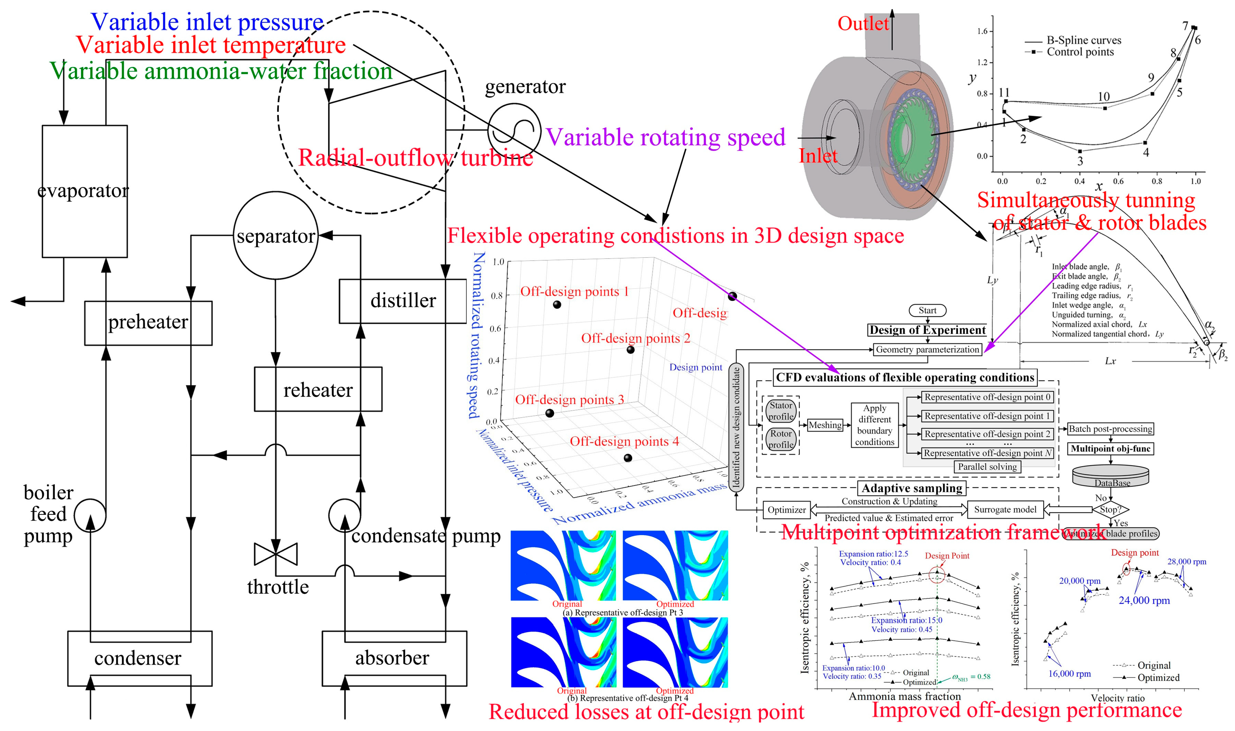
As presented in
Figure 1, the present study is motivated by the performance deterioration of an ammonia-water radial-outflow turbine, where the measured turbine shaft power at off-design conditions can’t satisfy the requirement of the system. To enable the flexible operating conditions of the Kalina cycle system and enhance the turbine off-design performance, a multipoint design optimization method is proposed for the radial-outflow turbine. It integrates the highly efficient multipoint objective function and adaptive optimization algorithms. The former considers the flexible operational condition variations including the inlet pressure, rotating speed, and ammonia-water mass fraction. The later adaptive optimization algorithm enables the aim-oriented optimal searching and is capable to solve such a highly nonlinear and computationally costly design optimization problem with limited CFD callings.
The developed multipoint design method is adopted to improve the turbine performance under complex operating conditions. By performing the optimization, the nozzle and impeller blades are optimized simultaneously, and the obtained results demonstrate that the application of the proposed multipoint design optimization effectively eliminates the flow separation at various operating conditions; thus, the turbine off-design performance has been comprehensively improved.
2. Flow Analysis at Flexible Operating Conditions
2.1. Physical Model and Grid Generation
As shown in
Table 1, at the design condition, the ammonia-water mixture with 58% mass fraction is expanded from 2.245 MPa to 0.179 MPa, where 224.83 kW of shaft power is produced with an isentropic efficiency of 81.28%.
The main geometry parameters of the initial designed turbine blades are present in
Table 2. They include 27 nozzle vanes and 29 impeller blades, and the blade height is quite low, i.e., 3.6 mm. It indicates a significant end-wall effect.
2.1.1. Physical Model
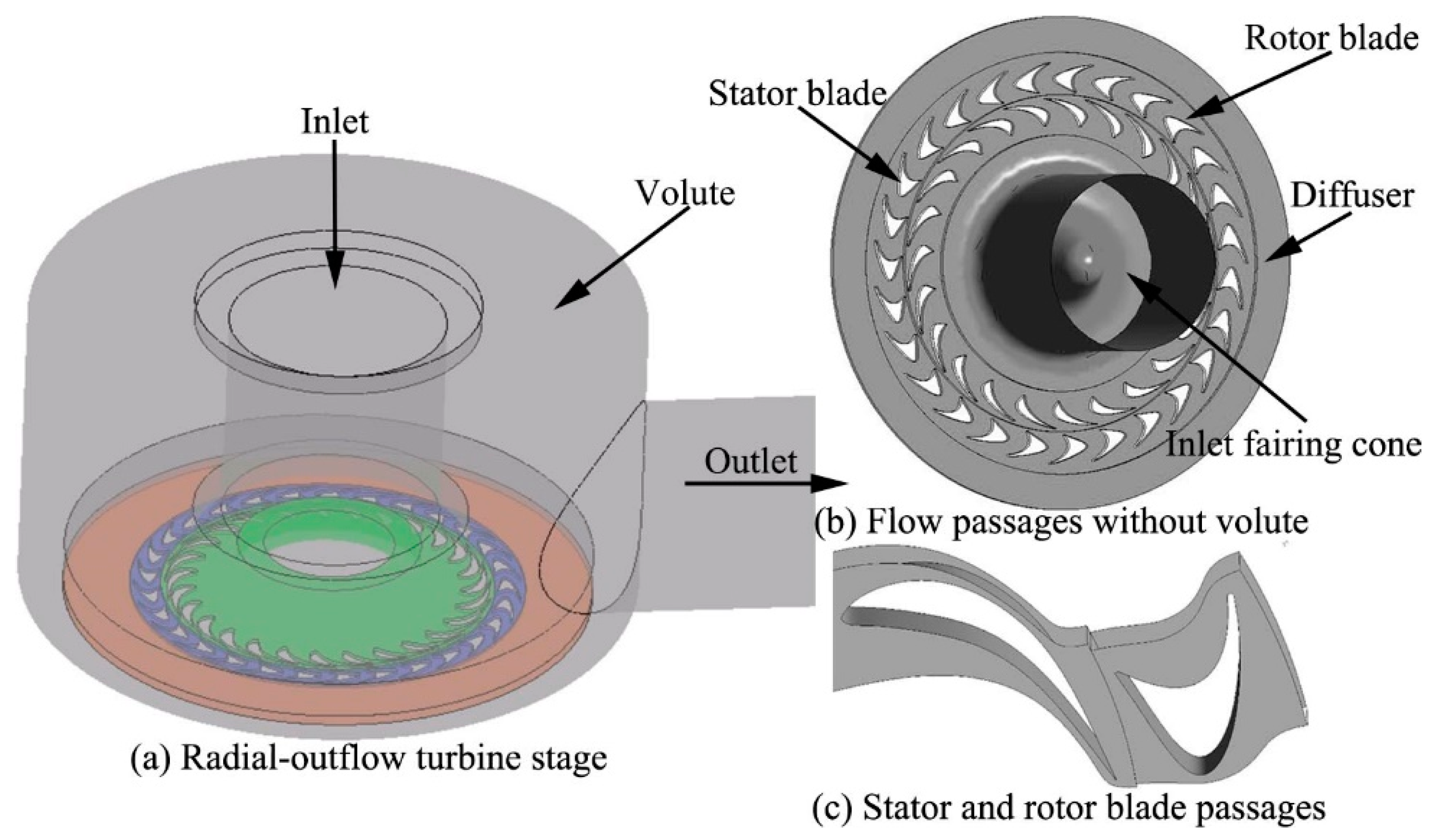
In order to obtain the realistic flow and performance prediction, the CFD simulations are performed on the entire turbine stage. As shown in
Figure 2, the physical model includes the inlet fairing cone, nozzle ring rotor blade row, a vaneless diffuser, and volute. As shown in
Figure 1, the gas flows into the turbine with the guide of the inlet fairing cone and flows through the stator and rotor blade passages, then flows out of the turbine through the vaneless diffuser and volute.
2.1.2. Grid Generation
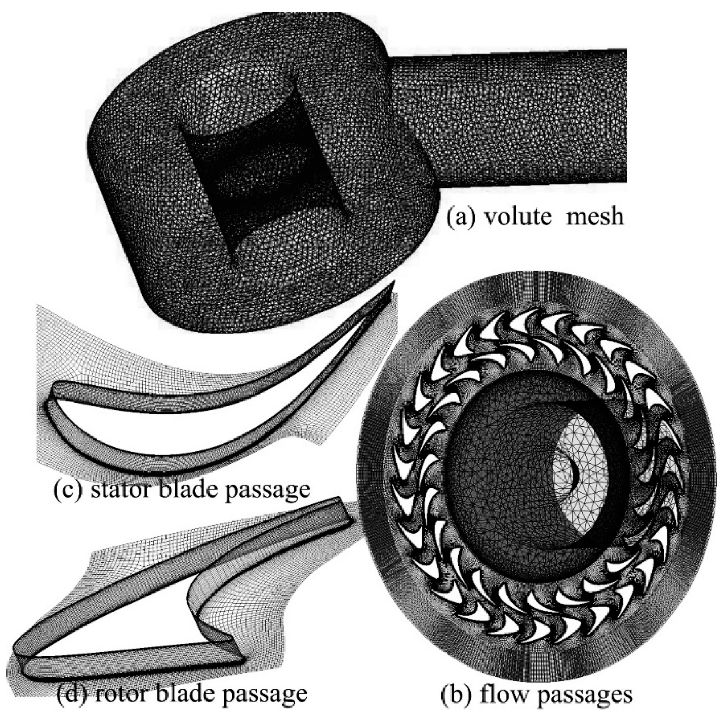
In the present study, TUBOGRID is adopted to produce multiblock structured meshes for the stator and rotor flow passages, while ICEM-CFD is used for the grids of inlet fairing cone, vaneless diffuser, and volute zone. As shown in
Figure 3, the meshes are refined locally in the wall and interfaces, such as the end-wall regions, as shown in
Figure 3c. As the simulation is performed, the values of y+ are checked. They are between 20 to 50 near the blade surfaces and boundary walls and satisfy the requirement of the k-e turbulence model [
30]. The grids for all the components are connected to form the entire mesh, as is shown in
Figure 3a.
2.2. Ammonia-Water Physical Properties Definition
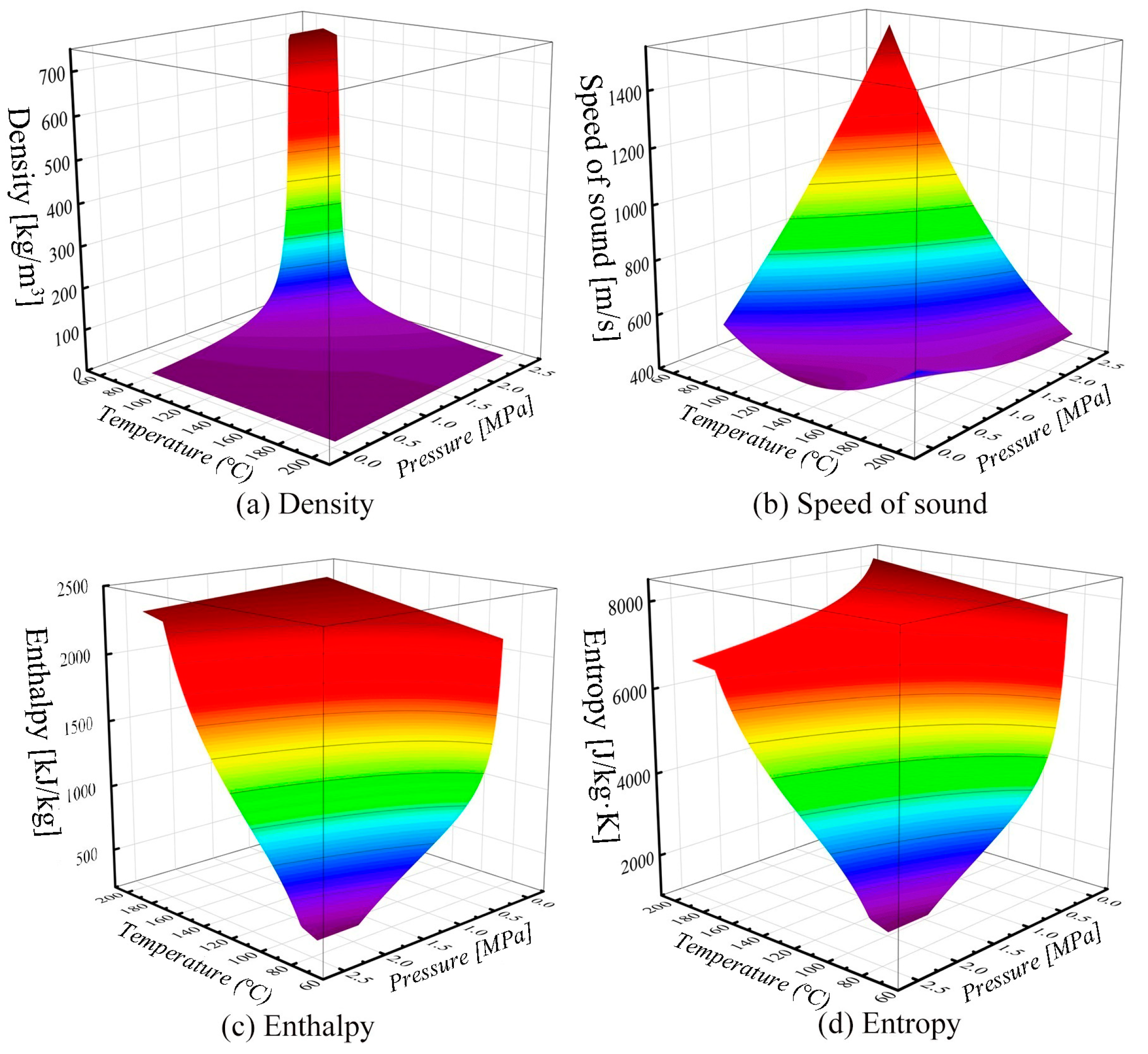
In the present study, the high-pressure and superheated ammonia-water gas flows into the turbine; its pressure energy transforms into velocity and drives the impeller to produce shaft power, then flows out of the turbine as a liquid-rich gas with lower pressure. In such a process, with a high expansion ratio of 12.5, the physical properties of the ammonia-water mixture vary significantly from turbine inlet to outlet. However, for the off-design conditions, the change of turbine operating conditions, especially the variations of ammonia-water mass fraction due to changes of the heat source or the cooling conditions, will influence the gas physical properties and result in a significant change in the power capacity of the turbine stage.
Figure 4 presents physical properties of the ammonia-water mixture, where the values of physical properties are also plotted in different colors. It is easy to find that the ammonia-water thermal properties, such as density, enthalpy, and entropy, are the functions of temperature and pressure. To enable an accurate calculation of ammonia-water physical properties, some work is performed by the authors to input its thermodynamic properties to CFX-Pre module, as is shown below.
The thermodynamic properties of ammonia-water mixture are calculated by the REFPROP software, where the “Tilner-Roth model for ammonia-water mixtures” mixing rule was adopted [
31]. The obtained thermodynamic property data were imported into the flow solver using the Real Gas Property (RGP) table file to enable variations of thermodynamic properties with both temperature and pressure.
2.3. Numerical Methods
Flow simulation is conducted in the turbine stage environment with ANSYS-CFX. The finite volume method is used with a combination of the second-order central scheme with artificial viscosity for the convective terms and the second-order central scheme for the diffusive terms. The standard two-equation k-e turbulent model with a scalable wall function was adopted to close the turbulence terms, which has been justified in transonic flow analysis [
32] and also widely used in the flow simulations of ORC turbine [
33,
34]. Moreover, a total energy model was adopted to reflect the variations of temperature.
The total pressure inlet and static pressure outlet is set as the inlet and outlet boundary conditions. No-slip and adiabatic conditions are specified to blade surfaces and end-wall regions. The frozen rotor model is applied at the stator–rotor and rotor–diffuser interfaces. Such a model produces a robust solution with less computation cost [
30].
To obtain a converged solution, the solver is monitored, where the total residuals of pressure, velocity, and heat transfer items must be less than 10−5, the mass flow deviations from the inlet to outlet must be less than 0.1%, and the variation of the monitored parameters, e.g., the temperature and torque, must not be greater than 1‰ in the last 100 solver steps.
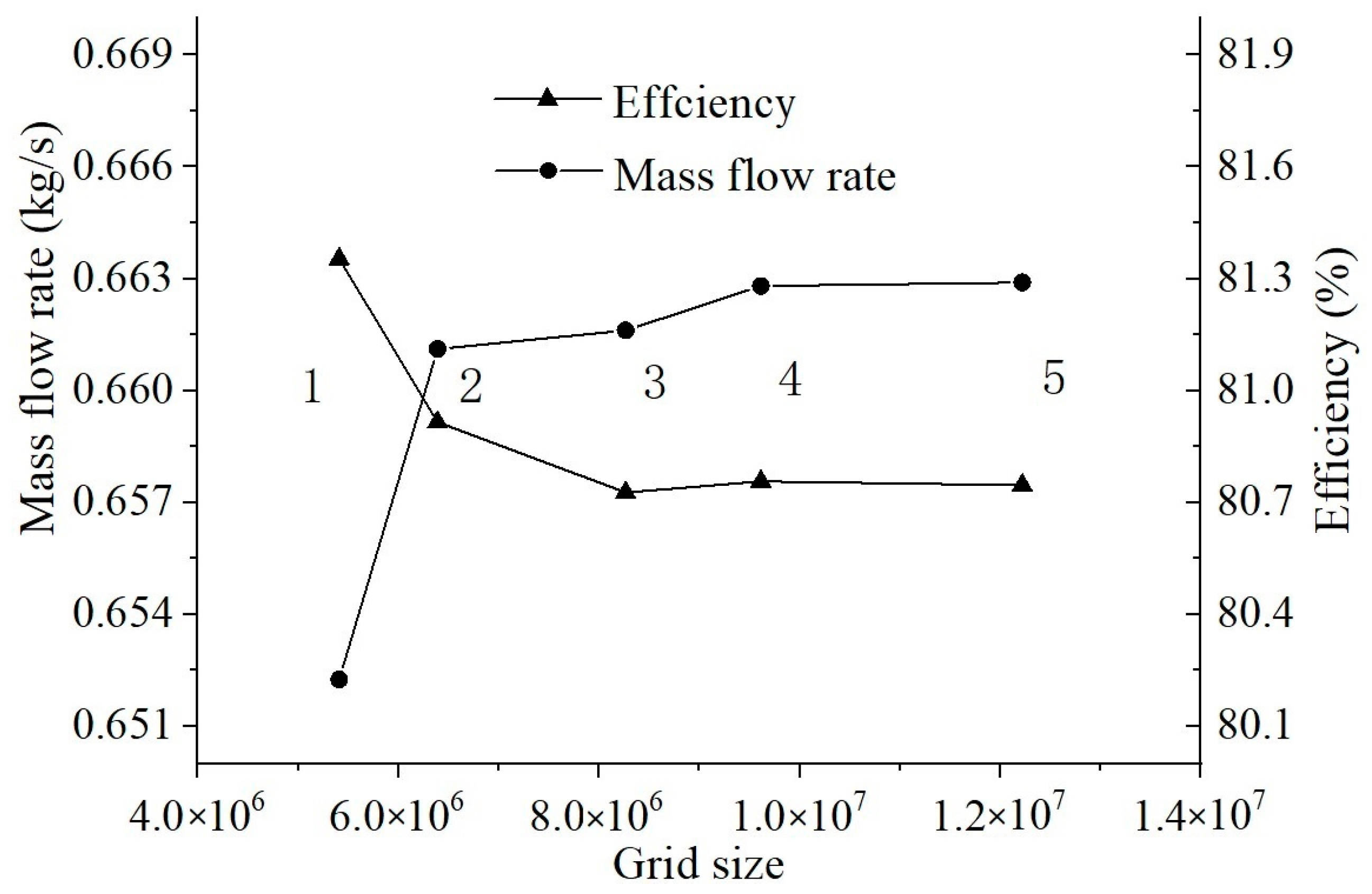
2.4. Grid-Independency Study
The grid-independency study is conducted at five different resolution grids, as marked by 1 to 5. As shown in
Table 3, the sizes of mesh 1 are 2,138,672 for the stator blades and 2,526,451 for the rotor blades; on this basis, the meshes for stator and rotor blades are refined, and those for the fairing cone, diffuser, and volute are held unchanged.
Figure 5 compares the predicted results with different mesh sizes. As shown in the figure, for the mesh sizes lower than mesh 4, the predicted mass flow rate and efficiency are significant. For the mesh sizes larger than mesh 4, the differences are very small, but the solving time increases largely. Thus, the size of mesh 4 is used in the present study.
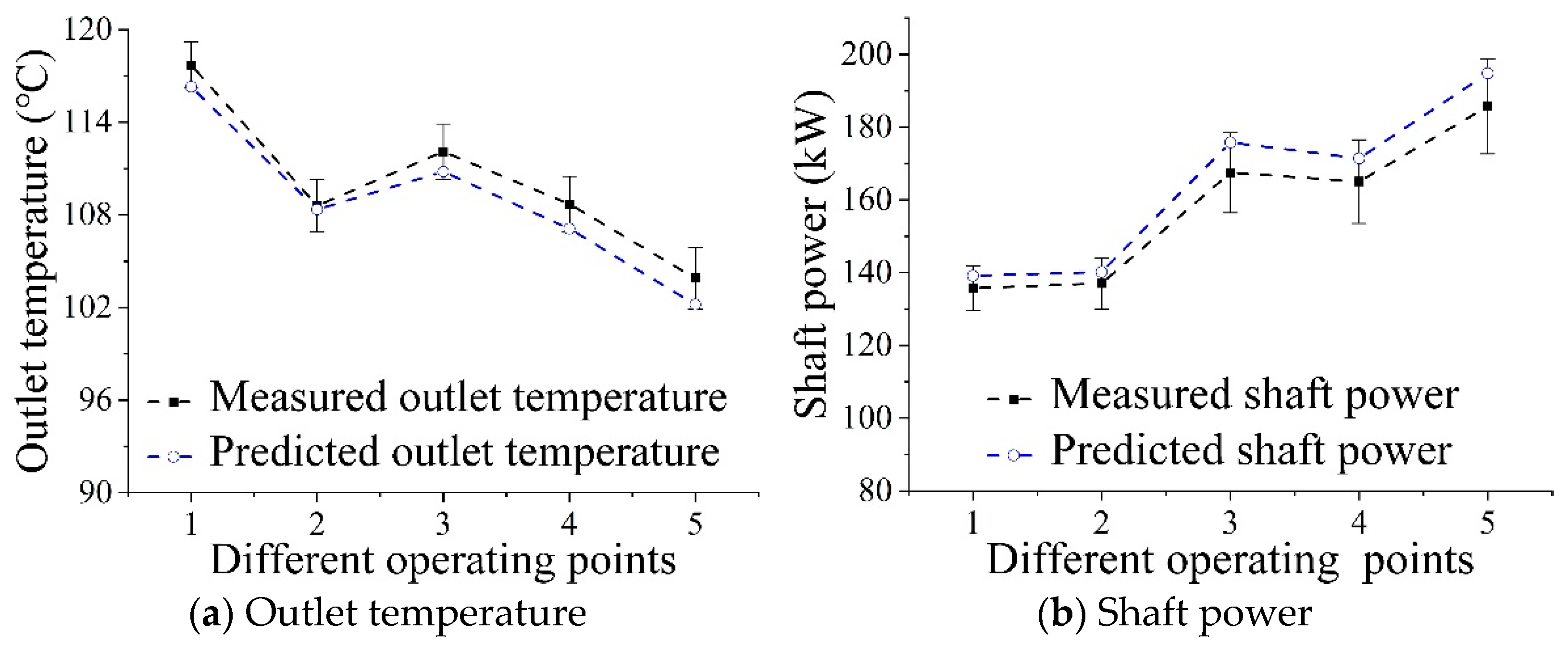
2.5. Validation of Numerical Methods
The measured turbine data from a closed-loop Kalina cycle power generation system were used for numerical methods validation, where the flow simulations are conducted at five tested points using the real operating parameters.
Figure 6a presents the predicted temperature with the measured ones at five operating points: the predicted values are slightly lower than the measured ones, and the maximum deviation is less than 2 °C. It is noticed that the temperature drop from turbine inlet to outlet is about 90 °C. In consideration of the instrumental errors, the predicted values agree well with the measured ones.
As is shown in
Figure 6b, the predicted shaft power values are slightly larger than the measured value, but the relative differences have some similarities at different operating conditions. It is noticed that the measured shaft power is obtained based on the measured generator power and corrected considering the bearing losses, gearbox loss, and generator efficiency. It is noticed that the maximum deviation of the shaft power is less than 5%. In consideration of the measurement errors of all the parts, the numerical approach provides a good prediction of shaft power.
Based on the above comparisons, it is considered that the CFD prediction error is acceptable, and the numerical methods for turbine flow simulation are justified.
2.6. Flow Analysis
The numerical simulations are conducted for the original designed radial-outflow turbine with the described CFD models. The obtained results are discussed below.
2.6.1. Flow Analysis at Design Condition
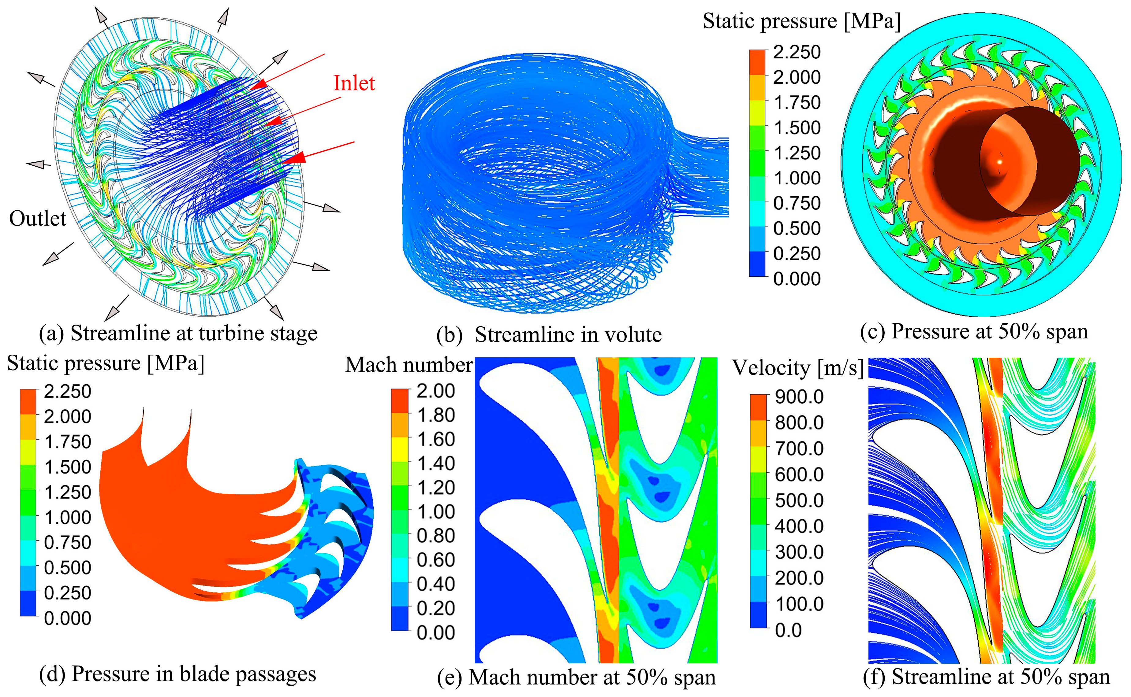
Figure 7 gives the design flow behavior of the original turbine. As shown in
Figure 7a, the gas flows into the turbine through the inlet fairing cone and turns from the axial to the radial direction. After flowing through the stator and rotor blade passages, it is gathered by the volute and flows out of the turbine, as is shown in
Figure 7b, while in
Figure 7c,d, most of the pressure drops occurs in the inlet fairing cone and stator blade passages. The pressure energy of the gas has been transformed into velocity in the stators. As shown in
Figure 7e, the transonic flow is observed in stator blade passages, and the maximal Mach number of 1.95 is reached at the stator outlet. In fact, a small reaction ratio of 0.05 is calculated, which indicates that the turbine is a pulse stage. As shown in
Figure 7e, there is no significant flow separation, which indicates that a high-level design performance is achieved in the original design.
At shown above, the well-matched flow is presented at the design condition. As a result, an isentropic efficiency of 81.2% is calculated, which is supported by the well-structured flow behavior, as shown above.
2.6.2. Flow Analysis at Off-Design Operating Conditions
The predicted performance parameters at four off-design points are compared with that of the design points. As shown in
Table 4, the main parameters of the tested operating points have significant variations with the design ones, which cover different inlet/outlet pressure, ammonia mass fraction, and rotating speed: the ammonia mass fraction at all the off-design operating conditions, especially the conditions 2, 3, and 4, have a large difference with the designed value of 0.58; although the rotating speed of measured condition 2 and 3 is close to the design value, i.e., 24,000 rpm, their inlet and outlet pressure have not reached the design values. As shown in the table, such deviations significantly degrade the turbine performance, where the significantly reduced efficiency and shaft power are presented at the four off-design operating conditions. Clearly, the well-structured flow matching at design points has been deteriorated with the off-design operating parameters, which is discussed below.
The turbine overall efficiency is defined as the ratio of real shaft work to that of the isentropic process, as shown below.
where
is the real turbine shaft work,
is the ideal shaft work under isentropic conditions,
represents mass flow rate,
is inlet gas enthalpy, and
and
are the specific outlet enthalpy o for real and isentropic process, respectively.
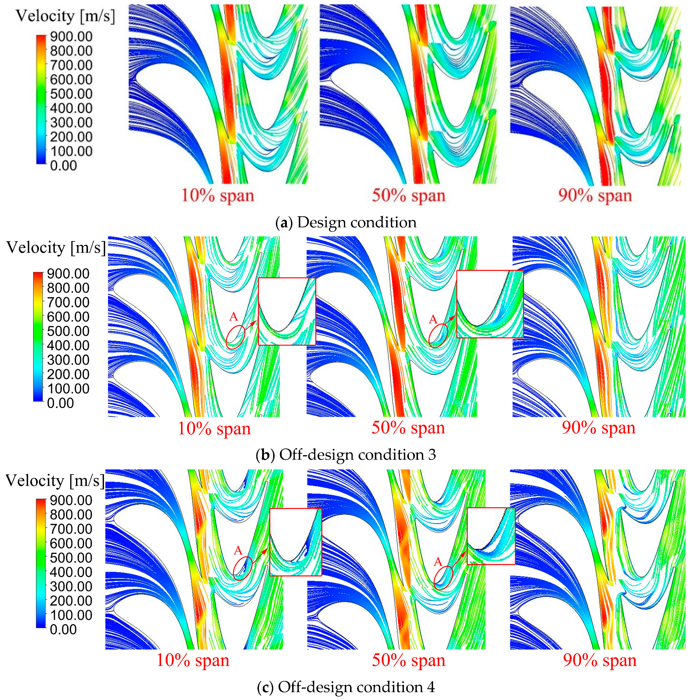
Figure 8 presents the predicted streamline patterns for the design conditions, off-design condition 3, and off-design condition 4, where the off-design condition 3 has a significantly lower ammonia mass fraction (0.476) as compared to the design value of 0.58, while off-design condition 4 has a significantly lower rotating speed (17,839 rpm) as compared to the design rotating speed (24,000 rpm) and a lower ammonia mass fraction of 0.463.
In comparison with the design condition, at off-design condition 3, visible flow separations present near the rotor blade suction surface, i.e., region A. At off-design condition 4, similar, but more intensive, flow separation is observed in region A. Such flow separations are arising from the destroyed flow matching under off-design conditions and enhanced by the large turning angle of the bowed rotor blade.
A quantitative demonstration of the flow losses could be presented in
Figure 9. Consistent with the exabits’ flow separations in
Figure 8, the main flow losses occur in the same position, region A. It is responsible for the deterioration in the expander’s overall performance (such as efficiency and shaft power) at off-design Pt 3 and 4 in
Table 2.
In a word, original turbine may not satisfy the variation of flexible operating conditions. To enhance the turbine off-design performance to support flexible operations of the Kalina cycle system, it is essential to consider the turbine performance over widespread conditions in the design stage.
3. Multipoint Optimization
As mentioned above, the operating condition of the ammonia-water system often deviates from its design value due to the variation of the heat source or the cooling conditions. However, the original designed turbine may not satisfy the variation of flexible operating conditions due to the deteriorated flow. In the present study, multipoint optimization is performed further to improve the turbine off-design flow behavior.
3.1. Setup of Multipoint Optimization
3.1.1. Definition of Flexible Operating Conditions
The ammonia-water turbine operates at wide operating ranges of ammonia mass fraction, inlet pressure and temperature, and outlet pressure and rotating speed. To define the flexible operating conditions with an affordable number of design parameters, two assumptions were made:
First, the outlet pressure
remains unchanged; thus, the inlet pressure is only related to the expansion ratio,
, as is shown in Equation (2).
Second, gas at the turbine inlet is in a saturated state. With such an assumption, the inlet temperature
could be determined by the saturation line equation according to the inlet pressure
and ammonia mass fraction
and finally related to dimensionless parameter
and
, as is shown in Equation (3).
As for the rotating speed, it is related to the velocity ratio
. The velocity ratio
is defined as
In Equation (4),
is the impeller peripheral speed, which is determined by impeller outer radius
and rotating speed
n.
is enthalpy drop in isentropic process, which is in connection with the gas inlet and outlet of parameters and finally related to dimensionless parameter
and
, as is shown in below.
Thus, the rotating speed
could be defined by the dimensionless parameters
,
, and
through the following equation.
Based on the above assumptions, the various operating conditions could be defined using three critical dimensionless parameters: the ammonia mass fraction , expansion ratio , and the velocity ratio .
3.1.2. Objective Function for Multipoint Design Optimization
The ranges of ammonia mass fraction
, expansion ratio
, and velocity ratio
are detected as:
To satisfy the operating requirement of the Kalina cycle system, various combinations of operating parameters must be properly considered. As discussed above, the flexible operating has been defined by three critical dimensionless parameters, and they cover a wide range in a 3D operating space. Nonetheless, since the flow simulations are time-consuming, it is difficult to consider all the flexible conditions.
In the present study, a small number of representative points are selected in the operating spaces using the Uniform Design Experimentation (UDE) approach [
35]. In the present study, three dimensionless operating parameters (i.e., the ammonia mass fraction, expansion ratio, and the velocity ratio) are used, and each of them is divided uniformly into five levels.
As shown in
Table 5, the ammonia mass fraction, expansion ratio, and velocity ratio are all divided into five levels between 0 to 1. Different levels of each parameter are specified to a different design point. By such a manner, it is clear that the representative off-design points are selected and uniformly distributed in the 3D operating parameter space.
The optimization objective function is defined based on the performance of the identified representative off-design points
where
denotes the isentropic efficiency, the subscript
represents the design point, and
represents the representative off-des Pt 1–5.
denotes the design variables, which contain the stator control point coordinates geometry parameters of rotor blades, as shown in
Section 3.1.1.
The optimization function (8) is used to drive the optimizer to permit the flexible variations of stator and rotor blades and improve both the design and off-design performance. Since the representative off-design points cover the flexible operating conditions, the multipoint optimization can effectively prevent the performance deterioration at off-design conditions.
3.1.3. Blade Geometric Representation and Optimization Variables
In the present study, two-dimensional stator and rotor blades are adopted for the radial-outflow turbine. Thus, rotor and stator could be simply described by their sectional profiles.
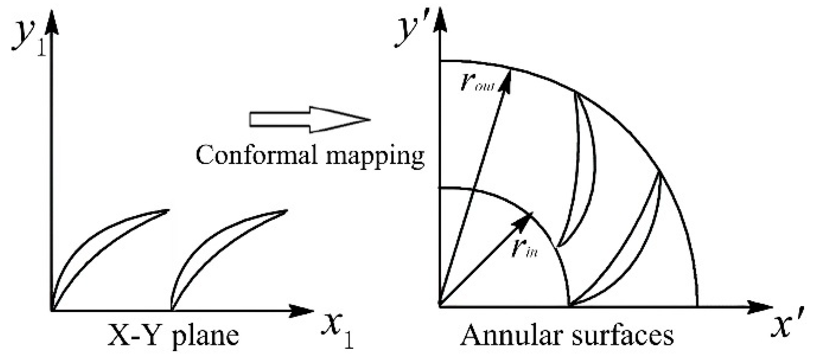
As shown in
Figure 10, The stator and rotor blades reside at the annular surface; to facilitate the geometry optimization, their sectional profiles are defined in the X–Y plane, and then they are transformed into annular surfaces through the conformal mapping method using Equation (9).
where
A and
B are complex numbers and used for conformal mapping;
rin and
rout are the inlet and outlet radii of the annular blade, respectively; and
real() and
imag() denote the real and imaginary parts of the complex number, respectively.
Stator Blade
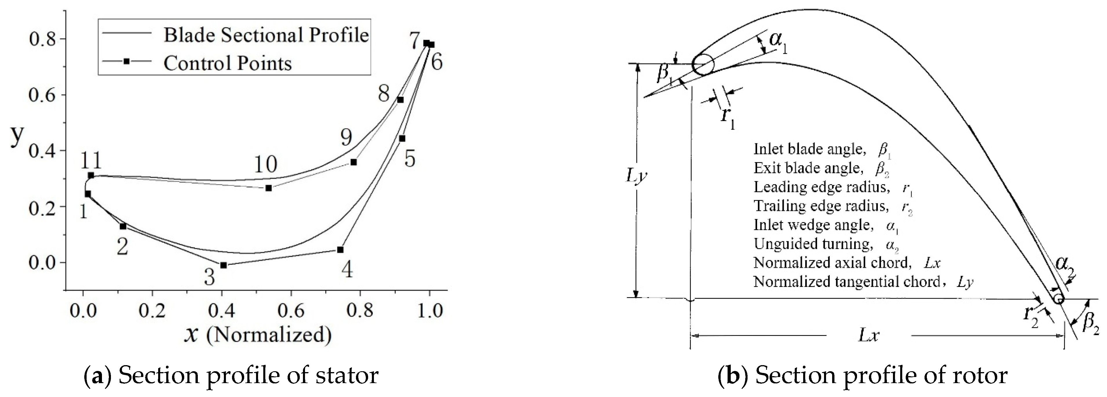
As shown in
Figure 11a, the main body of stator blades are represented by two B-Spline curves, where the leading- and trailing-edge arcs are constant. During optimization, the curves are adjusted by moving the position of the control points. To reduce the number of variables and optimal searching cost, the leading edge (point 1 and 11) and trailing edge (point 6 and 7) are fixed, and only the vertical coordinates of point 2, 3, 4, 5, 8, 9, and 10 are used. Thus, there are seven variables in total for the stator blade tunning.
Rotor Blade
In the present study, the Eleven-Parameter Method (EPM) is used for rotor geometry parameterization [
36]. As shown in
Figure 11b, it provides a comprehensive model for blade design, where several geometric parameters with definite physical meanings are used for rotor blade definition. The geometric parametric-sensitive study is conducted, and after that, five geometric variables are optimized: the inlet blade angle
, exit blade angle
, inlet wedge angle
, unguided turning
, and normalized tangential chord
Ly.
In total, there are 12 variables for the stator and rotor blade tunning.
3.2. Implementation
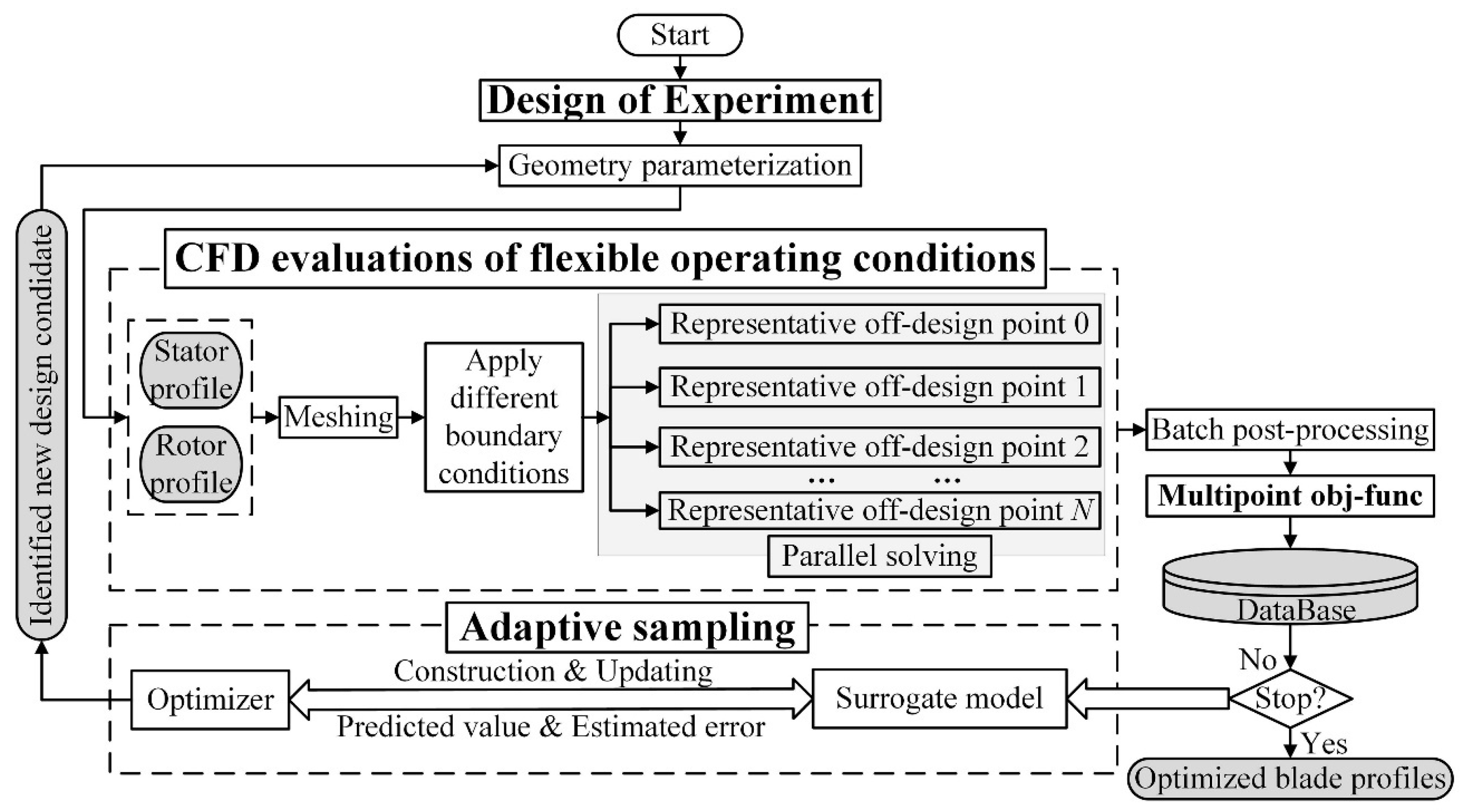
The flow chart of multipoint optimization for the radial-outflow turbine is presented in
Figure 12. As shown in the figure, it includes four main modules, including ‘Design of Experiment’, ‘Adaptive Sampling’, ‘CFD evaluations of flexible operating conditions’, and ‘Multipoint Objective Function’. They are performed with the following steps: firstly, a portion of design candidates identified by DOE are predicted using numerical simulations; then, the surrogate model is established for replacing the time-consuming CFD evaluations; secondly, design candidates are successively identified by adaptive sampling; then, CFD evaluations are automatically performed at flexible operating conditions, and the calculated multipoint objective function value is used for updating the model and successive optimization. By using adaptive sampling, only a few numbers of design candidates are evaluated to improve the accuracy of the surrogate model and reduce the CFD callings. The detailed introduction to the adaptive sampling is presented in [
37].
4. Optimization Results and Discussion
The optimization converges in 260 h to a PC workstation with a 28 core CPU processor, where 90 design candidates in total are evaluated during optimization.
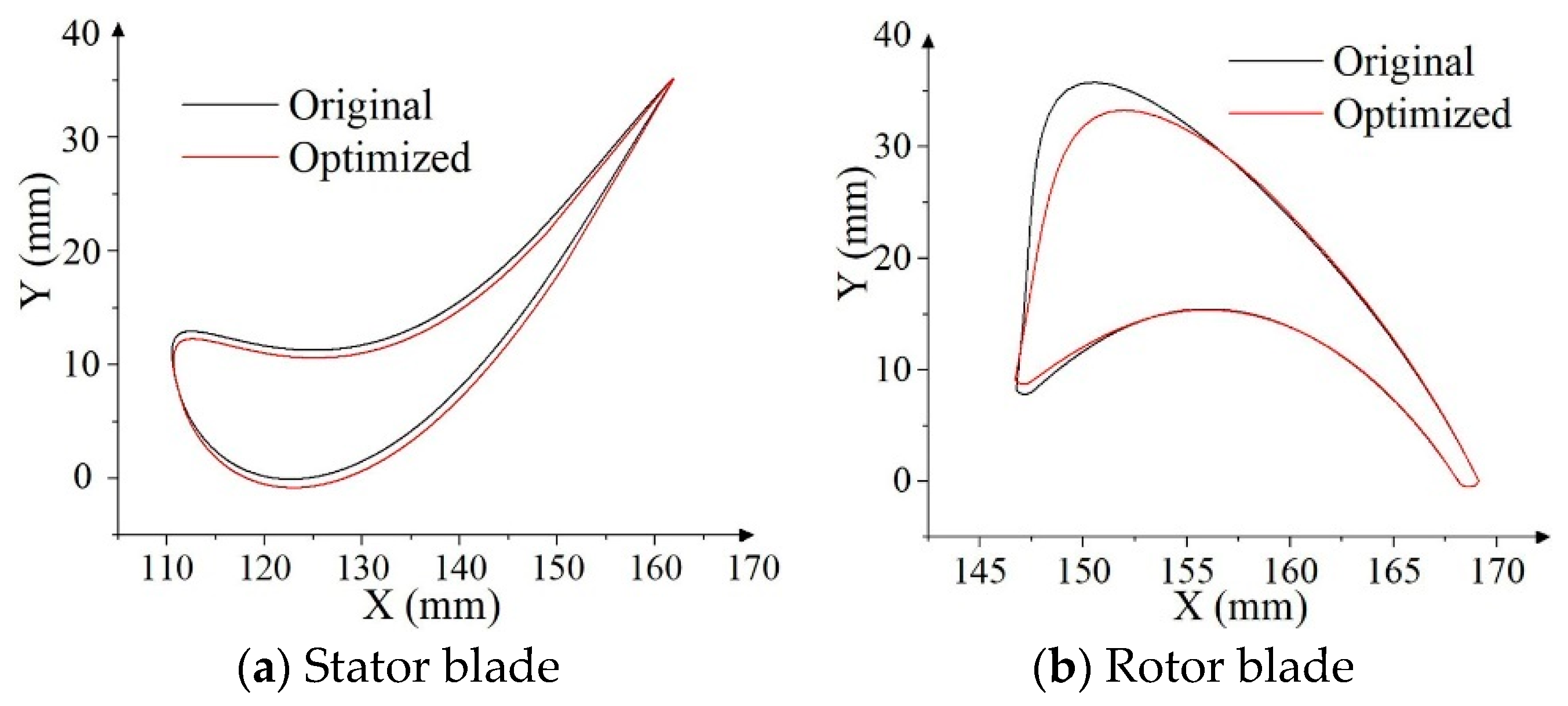
The optimized stator and rotor shapes are plotted in
Figure 13, where the original blade profiles are given as a datum baseline. As shown in the figure, significant variations in stator and rotor profiles are produced through multipoint optimization. Both sides of the stator blade profile were significantly optimized, and the significant variations of inlet blade angle and the bowed curve are produced on the rotor.
Such flexible tuning of stator and rotor geometry is favorable for the turbine performance over multiple operating conditions, which are discussed below.
Table 6 presents the optimized turbine performance at design and five representative off-design points. As for the design Pt and representative off-design Pts 1, 2, and 5, the multipoint optimized turbine performances are slightly less than that of the original. Except for the representative off-design Pts 3 and 4, the optimized performances significantly outperform the original. Especially at the off-design Pt 4, the original turbine efficiency is quite low due to the lowest velocity ratio and the deviations of expansion ratio and ammonia mass fraction. Benefitting from the multipoint optimized blade geometries, the turbine efficiency and shaft power are improved by more than 3%.
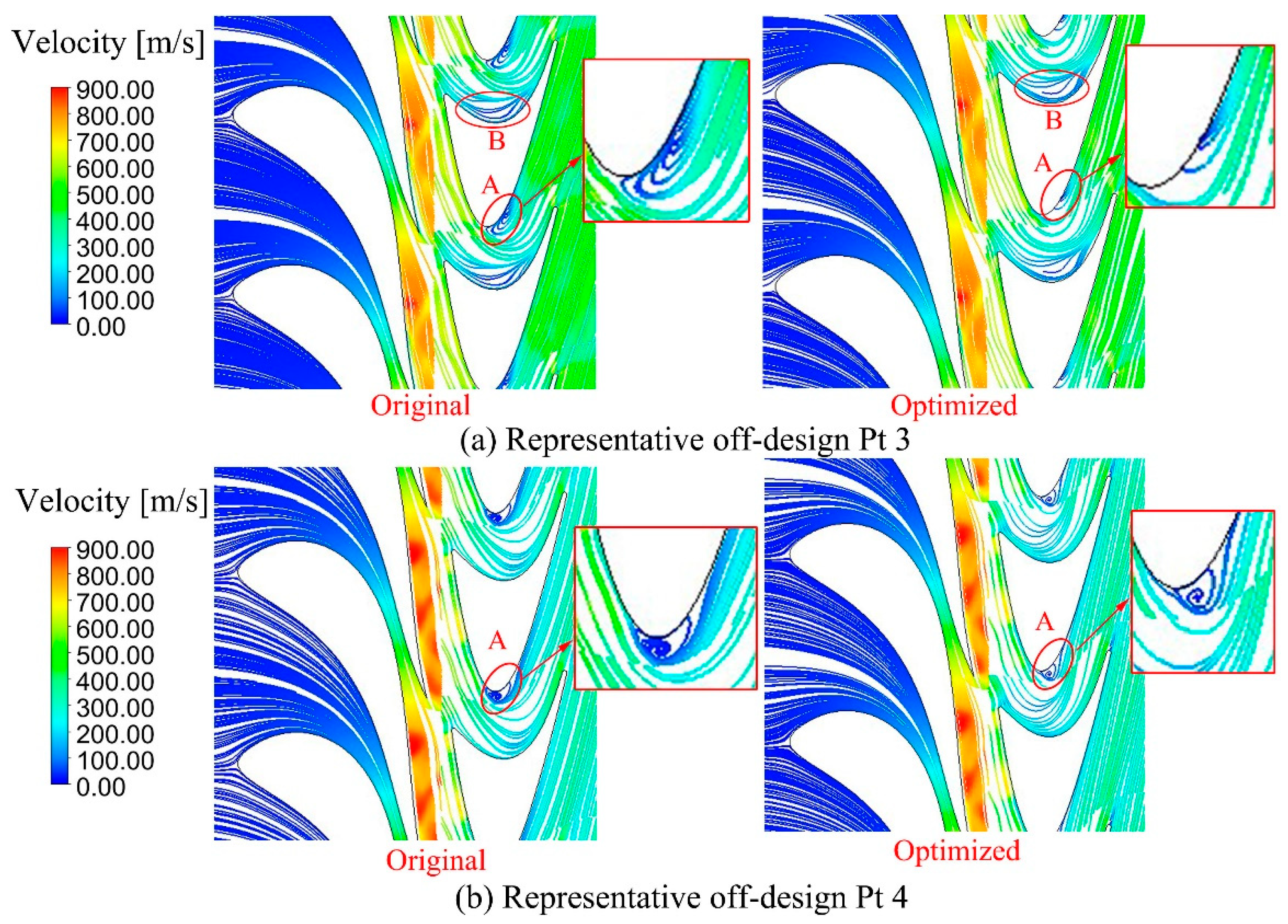
Figure 14 compares the flow behavior of the original and optimized turbine at representative off-design Pts 3 and 4. As shown in the figure, at representative off-design Pt 3, there are two separation flow regions, i.e., A and B, which may largely be due to the mismatched rotor/stator flow and the large turning angle of the bowed rotor blade. Benefitting from the optimized stator and rotor blades, flow separation in region A was effectively suppressed. A similar improvement was also made at representative off-design Pt 4, where the flow separation in region A is greatly reduced.
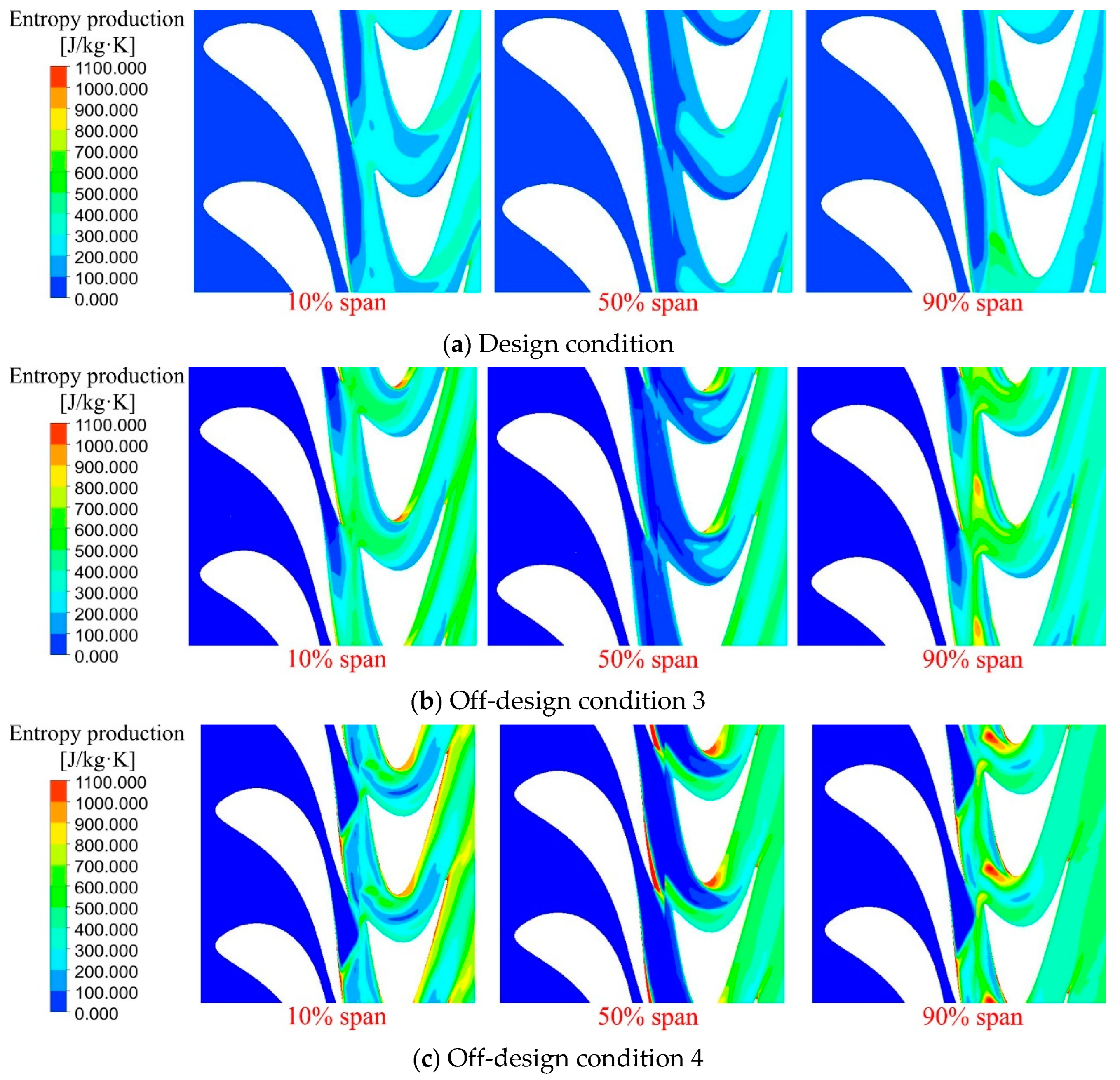
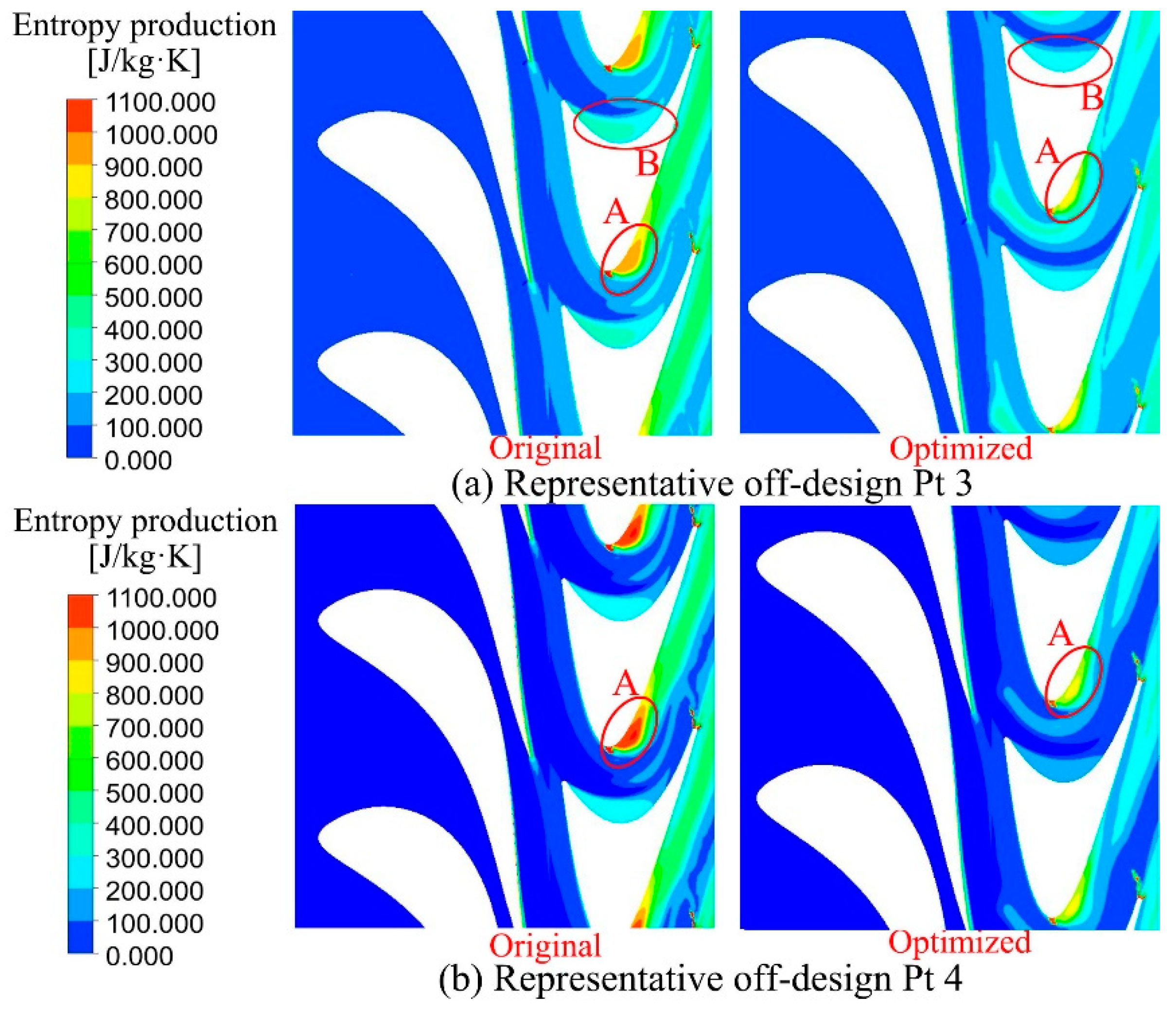
As shown in
Figure 15, the entropy production in optimized blade passages is reduced remarkably, where the scope and size in region A is evidently decreased. It indicates the reduced flow losses and enhanced performance improvement in
Table 6.
As indicated by the optimization results, the application of the multipoint design optimization effectively eliminates the flow separation at different operating conditions; thus, the turbine off-design performance was effectively improved. It is discussed below.
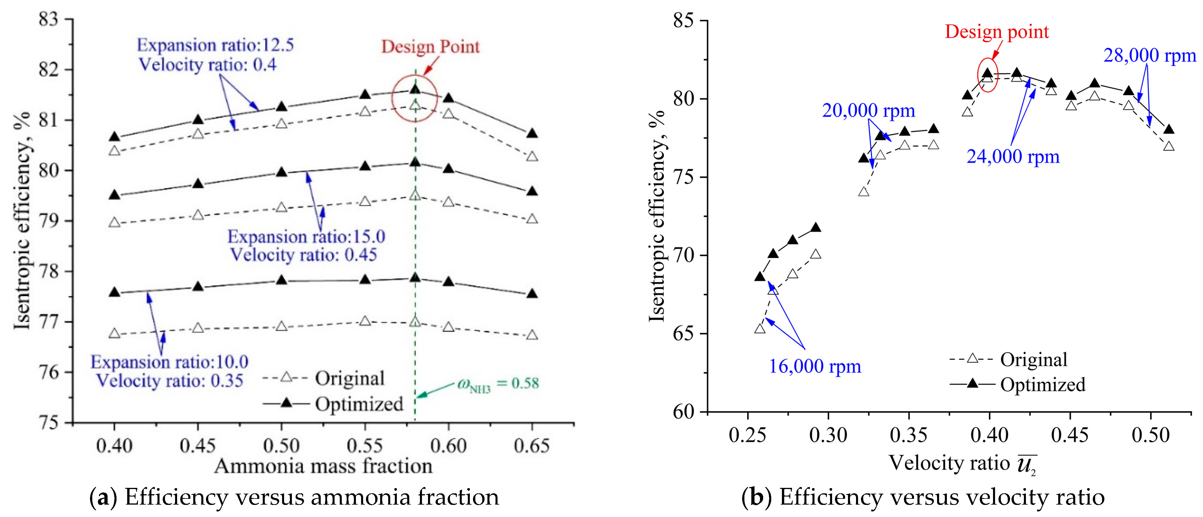
Figure 16 presents original and optimized efficiency curves: compared to the variations of ammonia-water mass fraction, the influences of the expansion ratio and velocity ratio are significantly larger. The range of 0.35–0.5 for the velocity ratio is a prior choice; in this scope, the turbine generally maintains a fair efficiency level. When the velocity ratio deviates from its design value and goes down, significant performance deterioration is presented.
Figure 16a compares the original and optimized isentropic efficiency curves versus ammonia mass fraction with different inlet pressure and rotating speed. For the original efficiency curves with different expansion ratio and velocity ratio, the turbine efficiency achieves its peak value at the ammonia mass fraction of 0.58 (design value), but the influence of ammonia fraction on efficiency is less than 1%. With the optimized stator and rotor blades, overall, the efficiency curves show a similar trend with a different expansion ratio and velocity ratio, but the optimized curves lie fairly above the original.
Figure 16b compares the multipoint optimized turbine efficiency curves versus velocity ratio at four rotating speeds. It is shown that both the velocity ratio and rotating speed have an evident influence on the turbine efficiency. With the optimized turbine blades, the efficiency curves lie fairly above the original at different rotating speed.
5. Concluding Remarks
The aim of the present study is to improve the off-design performance of the radial-outflow ammonia-water turbine to support the flexible operation of the Kalina cycle system. By integrating a self-defined multipoint objective function and adaptive optimizer, design optimization is applied in the geometry redesign of turbine blades. The conclusions are summarized below.
As the system operating conditions change, both the turbine inlet parameters and the generator rotating speed have evident influences on the turbine performance. The reason is that the original geometry of the blades is tuned to enable a well-matched flow at the design condition but does not consider the off-design flow. The off-design flow deviations lead to the flow separation and significantly reduce turbine efficiency.
By using the dimensionless parameters, the established objective function considered the flexible operational conditions, including different inlet pressure, ammonia-water mass fraction, and rotating speed. The use of a uniform design experimentation scheme makes the defined objective function covers vary regarding the combination of parameters in multiple design spaces with limited reprehensive off-design points.
The developed optimization method has been applied to optimize a radial-outflow turbine in the Kalina cycle-based energy recovery system. A flexible blade shape variation is realized, and rotor and stator blades are adjusted simultaneously to improve the flow behavior. The adaptive optimization codes are adopted to permit an aim-oriented optimal searching with significantly reduced simulation time. The obtained results demonstrate that the application of the multipoint design optimization effectively eliminates the flow separation at different operating conditions; thus, the turbine off-design performance has been effectively improved.


