Article

The Recycling of Waste Per-Fluorinated Sulfonic Acid for Reformulation and Membrane Application in Iron-Chromium Redox Flow Batteries

1
State Key Laboratory of Heavy Oil Processing, China University of Petroleum-Beijing, Beijing 102249, China
2
Zhonghai Energy Storage Technology (Beijing) Co., Ltd., Beijing 102200, China
*
Authors to whom correspondence should be addressed.
Energies 2022, 15(22), 8717; https://doi.org/10.3390/en15228717
Submission received: 30 October 2022 / Revised: 15 November 2022 / Accepted: 17 November 2022 / Published: 20 November 2022
(This article belongs to the Special Issue Emerging Materials for Energy Catalysis)

Abstract

:
Iron–chromium redox flow batteries (ICRFB) possess the advantage of low raw material cost, intrinsic safety, long charge–discharge cycle life, good life-cycle economy, and environmental friendliness, which has attracted attention from academia and industry over time. The proton exchange membrane (PEM) is an important part of the ICRFB system, impacting the efficiency and lifetime of the battery. Currently, the most widely used PEMs in the market are per-fluorinated sulfonic acid (PFSA) membranes, which possess high electrolyte stability and achieve the separation of positive and negative electrolytes. In addition, the complex preparation process and extremely high market price limited the usage of PEM in ICRFB. In this paper, we developed a remanufactured membrane (RM) strategy from waste PFSA resins. The RM has higher electrical conductivity and better proton transport ability than the commodity membrane N212. In the cell performance test, the RM exhibits similar coulombic efficiency (CE) as N212 at different current densities, which is stabilized at over 95%. Furthermore, the voltage efficiency (VE) and energy efficiency (EE) of the RM are improved compared to N212. At a current strength of 140 mA cm−2, the degree of energy loss is lower in the RM, and after 60 cycles, the capacity decay rate is lower by only 16.66%, leading to long-term battery life. It is a cost-effective method for membrane recovery and reformulation, which is suitable for large-scale application of ICRFB in the future.

1. Introduction

At present, the problem of resource shortages is becoming increasingly severe. The shortage of fossil energy resources worldwide is inevitable and the issue of energy and security has been defined as a global topic [1]. Due to the shortage of fossil-fuel energy and the problem of global warming, the demand for new energy sources is increasing [2]. However, renewable resources, such as solar [3] and wind [4], are limited by their instability and intermittency [5], which is an obstacle to meeting actual power supply requirements. At present, various technologies have been explored to store electricity from renewable sources, including electrochemical energy storage [6], pumped hydro energy storage [7], compressed air [8], flywheel energy storage [9]. As a new high-efficiency electrochemical energy storage technology, redox flow battery (RFB) technology has the advantages of high discharge capacity [10,11], excellent stability [12], and flexible assembly [13], and can achieve a service life of 20 years or longer compared with traditional batteries. Therefore, RFB is capable of meeting large-scale power storage demands, achieving low-cost and safe long-term energy storage [14]. As the first proposed RFB model [15], the iron–chromium redox flow battery (ICRFB) uses Fe3+/Fe2+ and Cr3+/Cr2+ as cathode and anode actives, which are cheap and readily available. Moreover, it has attracted attention because of its lower cost and longer cycle life than the most widely available commercial vanadium redox flow batteries. This technical route of ICRFB continues to attract more attention. With breakthroughs in green electricity, green hydrogen, and green ammonia demonstration projects in the chemical industry, and the rapid growth of sustainable energy, a second wave of chemical power technology is imminent. New application scenarios will also unlock new usage modes for RFB.
As one of the core parts of ICRFB, the proton conduction membrane can form a cell pathway for proton transformation during electrifying. Meanwhile, it can also prevent cross-contamination of active materials, which largely effects the cost and operating performance of ICRFB [16,17,18]. Based on the proton conduction membrane, per-fluorinated sulfonic acid (PFSA) is widely used in ICRFB because it has excellent chemical stability and good electrical conductivity [19,20,21]. The largest PFSA membrane manufacturer is DuPont [22], whose products have an extremely high market price due to the complex synthesis of PFSA and the difficulty of sulfonation [23,24,25]. Therefore, more efficient and affordable alternatives should be developed. Zhang et al. attempted to use sulfonated polyether ether ketone (SPEEK) with polyethersulfone-resin porous composite membranes to replace Nafion membranes, possessing excellent working performance achieved over a wide pH range [26]. However, during the actual operation of the ICRFB, oxidation and high temperatures degrade and damage the SPEEK membranes, affecting their service life. Wang et al. used polyvinylidene fluoride/graphene to produce composite nanoporous membranes [27]; this can improve membrane selection and conductivity. However, the battery efficiency was lower compared to Nafion membranes. As noted above, the preferred choice for ICRFB applications remains the Nafion membrane. When the membrane reaches the end of its service life, it is often incinerated or discarded in landfills, which is not environmentally friendly and further increases the ICRFB cost. Until now, no studies on the recycling of PFSA resin and reapplication in ICRFB have been reported.
This paper proposes an effective method of recycling waste PFSA membranes in search of lower costs and similar performance. The commercially available N212 membrane is selected as the comparison item. The RM is made by dissolving and remanufacturing at 230 °C. The RM exhibits a similar coulomb efficiency (CE) of 97.46% with N212 at a current density of 140 mA cm−2. In comparison, the voltage efficiency (VE) and the energy efficiency (EE) of the RM are 81.36% and 79.29%, respectively, which are 0.64% and 0.48% higher than the original Nafion membrane. All results indicate that RM is a promising choice for large-scale, low-cost applications of ICRFB.

2. Experimental

2.1. Materials and Methods

2.1.1. Materials

The FeCl2∙4H2O, CrCl3∙6H2O and HCI used in this work were supplied by Sinopharm Chemical Reagent Co., Ltd. (Shanghai, China). Commercially available Nafion membrane N212 was selected as the control group and purchased from Kerun Company (Jiangsu, China). In addition, N, N-Dimethylformamide (DMF) was supplied by Shanghai Aladdin Biochemical Technology Co., Ltd. (Shanghai, China). H2O2 and H2SO4 were purchased from Beijing Beihua Fine Chemical Co., Ltd. (Beijing, China). All agents were used without further purification.

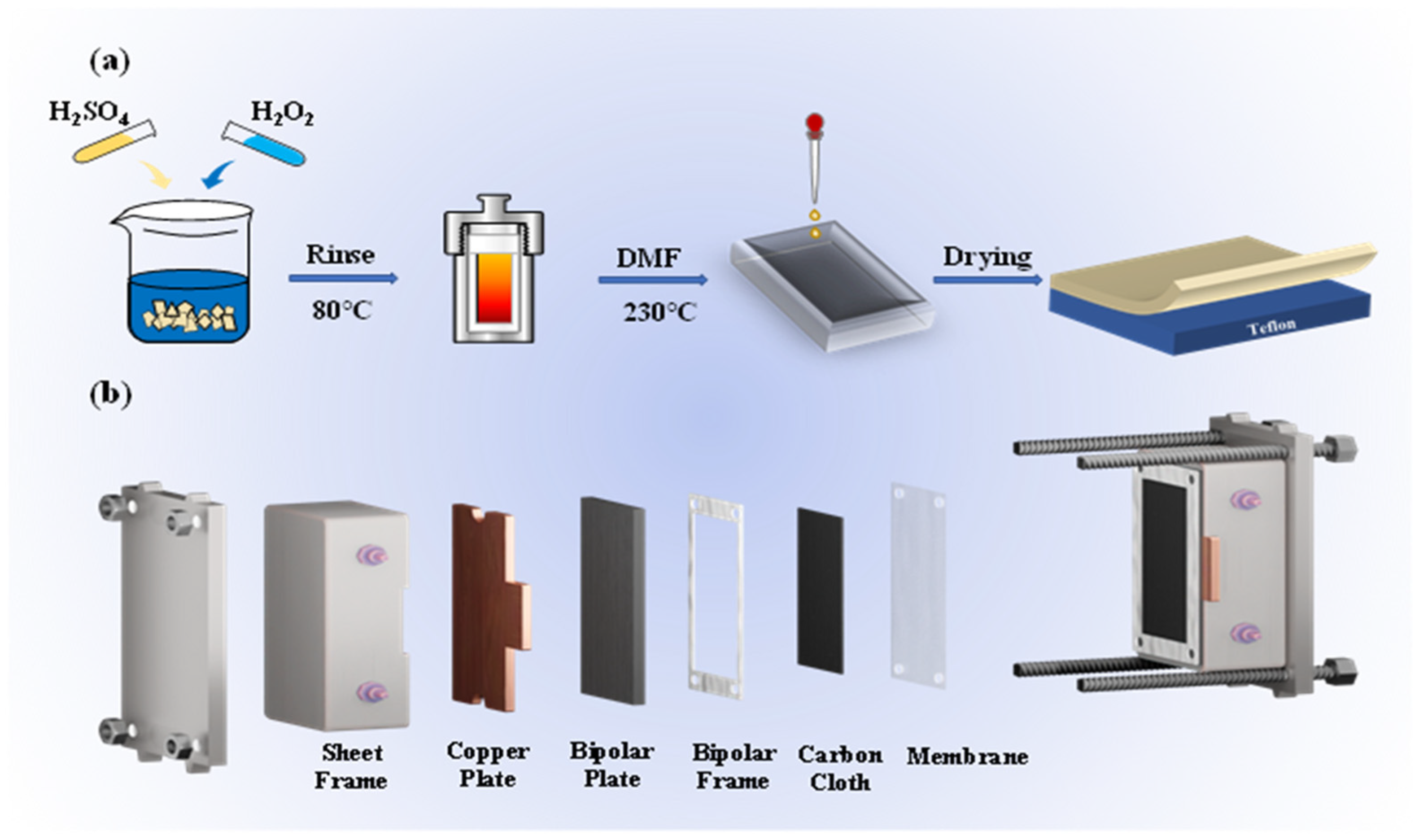
2.1.2. Method of Preparation and Reprocessing of Remanufactured Membrane

The discarded N212 membranes were cut into pieces smaller than 4 cm2. Firstly, they were washed by boiling deionized water at 60 °C for 60 min to remove surface impurities. They were boiled with 5 wt% H2O2 at 80 °C for 30–60 min, washed to remove the organic matter, then soaked in 0.5 mol L−1 H2SO4 solution at 80 °C for 30–60 min, then washed again. The cleaned and crushed PFSA membrane and DMF solution were put into the PTFE reactor. The reaction kettle was set at 230 °C under a vacuum oven for 12 h and removed after cooling. The filtrate was obtained and then centrifuged at 5000 r min−1 for 10 min, and the upper layer of liquid was discarded to obtain a 5 wt% H+ type PFSA resin organic solution.
The PFSA resin solution was poured into the casting tray, and the solution was allowed to spread evenly over the tray. The PFSA resin solution was heated from room temperature to 180 °C in a blast drying oven and dried until the solvent evaporated from the membrane. Once the solvent in the cast solution had evaporated, heating was continued for 10 min to ensure uniformity of the RM. At the end of heating, the membrane was allowed to completely cool before removal.
The RM was steamed in 1 mol L−1 H2SO4 at 80 °C and placed in a vacuum oven for 1 h. After removal, the membrane was rinsed with deionized water. Then it was soaked in 0.2 mol L−1 EDTA-2Naat 80 °C for 20 h. The membranes were repeatedly washed with deionized water and placed in deionized water at 80 °C for 1 h for heat treatment to remove the residual liquid inside the membranes altogether.

2.2. Characterization Methods

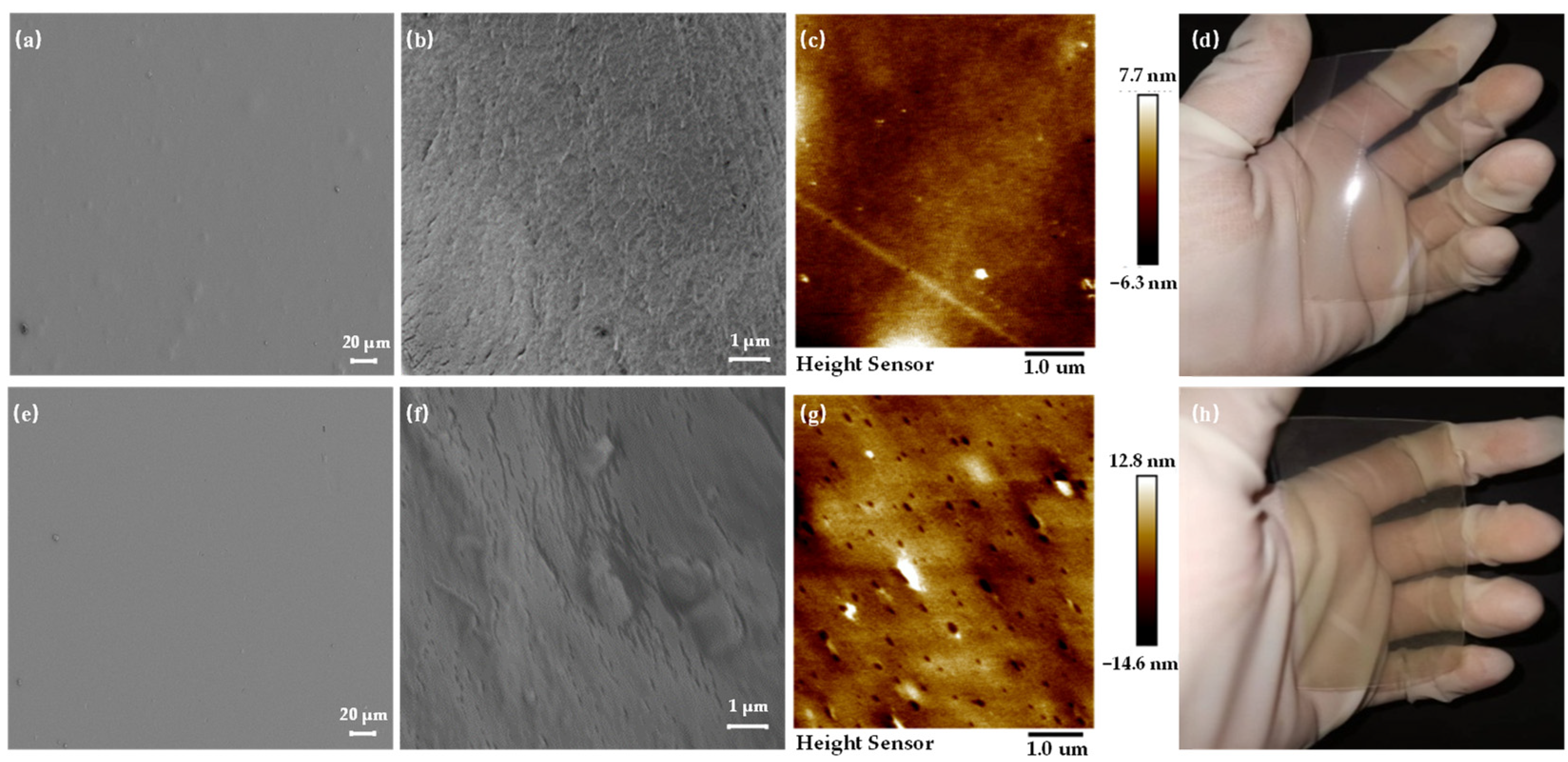
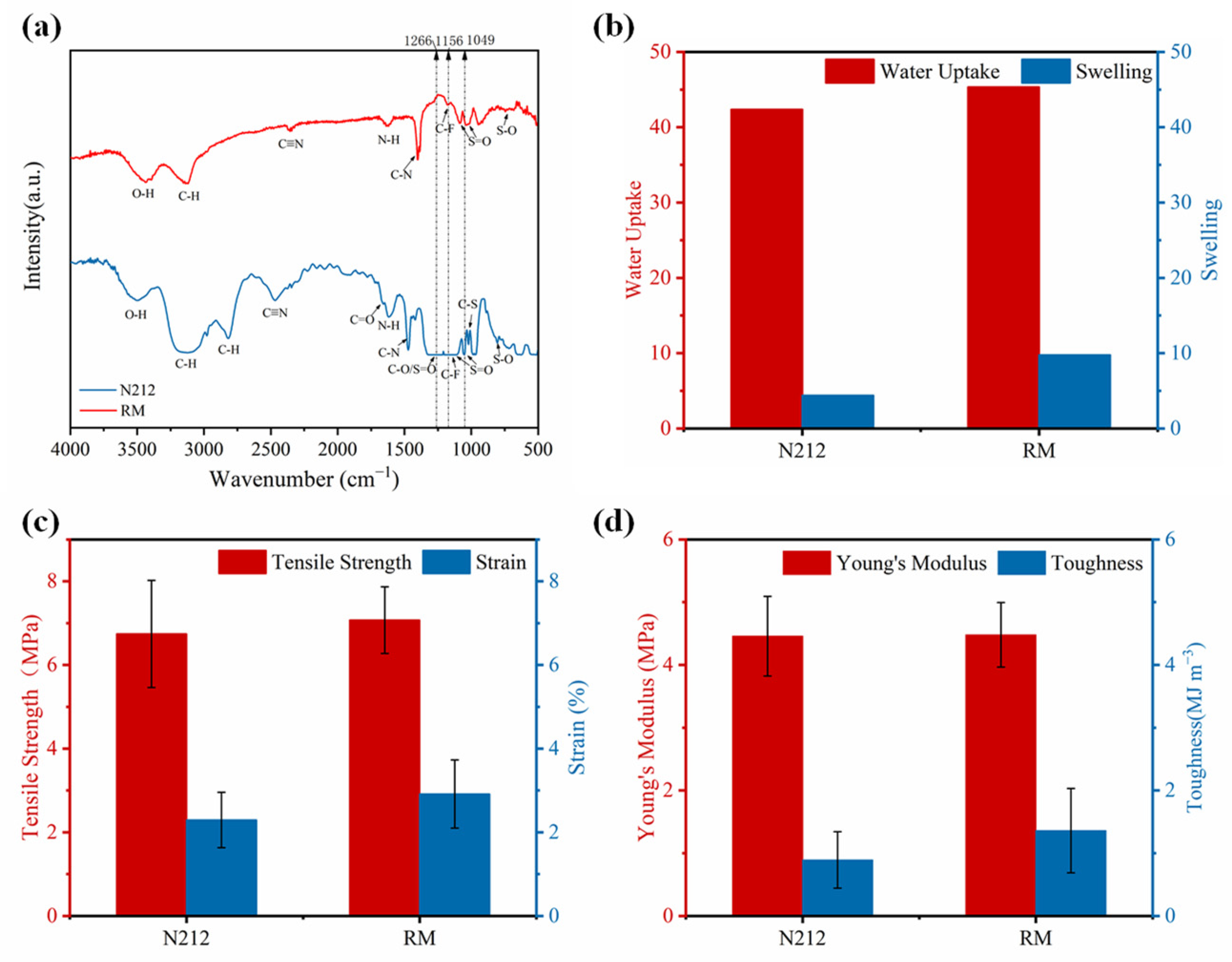
2.2.1. Membrane Characterization

Approximately 1 cm2 of the membrane sample was fixed to the AFM test paper with double-sided tape. AFM tests were performed using DualScope C-26 (Danish Micro Engineering, Saarbrucken, Germany) in the air by tapping to compare the surface morphology of N212 membranes and RM specimens. The membrane samples were dried, and the chemical structure of the samples was analyzed using Fourier transform infrared spectroscopy (FTIR, 1iS10, Waltham, MA, USA). The cross-sectional and surface morphology of N212 and RM samples were tested using SEM (Sigma 500, Oberkochen, Germany) at an accelerating voltage of 10 kV, and elemental analysis was performed. Membrane specimen cross-sections were obtained through the friability of liquid nitrogen, and samples were prepared on a T-table and coated using gold spray before imaging.

2.2.2. Water Absorption and Swelling Rate Test

The membranes were placed in deionized water for 72 h, and the excess water was quickly wiped off the surface after removal. The membranes were tested for water absorption and swelling before and after different impregnations, and their properties were analyzed.
Water absorption test:
Water   absorption = W s W d W d × 100 %
Ws and Wd are the weights of the saturated and dry membranes, respectively.
Swelling rate test:
Swelling   rate = L s L d L d × 100 %
Ls and Ld are the lengths of the saturated and dry membranes, respectively.

2.2.3. Membrane Conductivity Measurement

A membrane was placed between two porous gas diffusion electrodes, and the three were hot-pressed together in a hot press. The two electrodes were connected to the positive and negative terminals of the conductivity meter, and the difference in conductivity between the RM and N212 membrane was compared qualitatively under different humidity conditions by the conductivity meter.

2.2.4. Tensile Strength

The stress–strain curve of the membrane was measured using a universal dynamic tester (WAW-2000E, Chenda, Jinan, China).

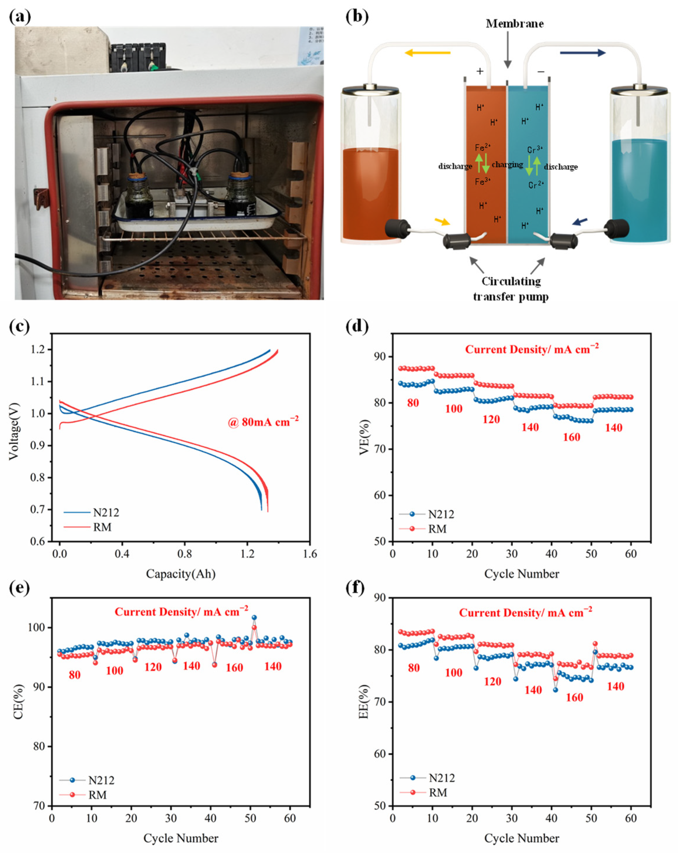
2.2.5. Single-Cell Testing

The battery tests were all performed on a single-cell testing system (Neware CT-4008-5V6A-DB-F, Shenzhen, China) with a homemade single-cell with a serpentine flow field. Carbon cloth with an active area of 2.0 cm × 5.0 cm was used as the negative and positive electrodes, and the different membranes were separated with remanufactured and commercial N212 membranes, respectively. The electrolyte was circulated at a constant flow rate of 9 mL min−1 by a two-way peristaltic pump (Shenchen, BT100N, Beijing, China). N2 was bubbled to remove air from the electrolyte and reservoir to avoid undesirable side effects.

3. Results and Discussion

3.1. Preparation and Characterization of Membranes

The hydrophobic structure of Teflon gives PFSA membranes excellent mechanical properties and stable performance. During ICRFB operation, electrode puncture of the septum and electrolyte cross-contamination are not easily observed. Hydrophilicity from the sulfonate improves the electrical conductivity of the membrane. It enables the construction of a complete circuit in the battery structure by selective permeation of ions. Therefore, it is of great practical importance to study the recycling of PFSA membranes. Hydrogen peroxide and sulfuric acid were used as cleaning agents.
DMF was used as a solvent to facilitate remanufacturing PFSA polymer segments at 230 °C and to enable ionic cluster formation during solvent evaporation of the membranes (Figure 1a). According to the previous report in [28], the high degree of ionic cluster binding within the PFSA during heat treatment at a certain temperature contributes to improving the membrane’s mechanical properties. In addition, Figure 1b shows the internal structure of the battery.
Compared with other Nafion membranes in different thicknesses, N212 has higher cost performance assembled by ICRFB [29]; therefore, N212 is used as the template for RM thickness selection. PFSA recycling is performed on discarded N212 membranes. N212 is selected as a comparison term to examine the various properties of RM. Figure 2 shows the characteristic surface morphologies of N212 and RM. Figure 2a,e show the SEM images of N212 and RM. The commodity membrane N212 and the RM have smooth surfaces, indicating that the RM is relatively complete. Comparing SEM cross-sections, the RM (Figure 2f and Figure S1b) possesses a structure density and thickness similar to N212 (Figure 2b and Figure S1a), both of which are 50 μm thick. Possessing the same thickness eliminates the effect of the membrane thickness itself on the performance of the ICRFB. The pore distribution in the N212 membrane is uniform. However, the cross-sectional morphology of the RM is much rougher, likely due to the irregular distribution of PFSA ion clusters during the membrane remanufacturing process. This condition is also confirmed in the AFM images, where the N212 surface-height distribution is very narrow (Figure 2c), while the surface of the RM is much rougher. Also, many defects are distributed on the surface (Figure 2g), which is most likely caused by excessive air bubbles due to DMF’s evaporation during the RM preparation. As shown in Figure 2d,h, there is little difference between the physical diagrams of N212 and the RM. Since the RM is rougher, the difference in membrane surface thickness may affect the specific surface area of the membrane, which in turn influences its battery performance.
Elemental analysis of N212 and RM has been performed to further confirm the successful preparation of PFSA membrane by recycling (Figure S2). The result shows that both N212 and RM contain the important elements of S and F. The chemical structure groups of N212 and RM have been analyzed by FTIR images (Figure 3a), and both membrane samples contain several typical stretching vibrational bands, including S=O bonds at 1049 cm−1, C-F bonds at 1156 cm−1, and S-O bonds at 750 to 1000 cm−1, showing that the RM forms long chains of Teflon and lateral sulfonic acid groups. As shown in Figure 3b, the water uptake of the RM membrane increased slightly after heat treatment at 230 °C. In addition, the contact angles of the two membranes were tested with the electrolyte before the cell test, and Figure S3 shows they have similar contact angles. Proton conductivity is an important parameter in ICRFB applications to verify the utility and design advantages of membranes in flow cell systems [30].
The RM needs to be high-strength and durable to prevent electrode punctures that lead to electrolyte cross-contamination in ICRFB operation. The RM shows similar tensile strength (Figure 3c) and Young’s modulus (Figure 3d) compared with N212, as well as superior strain (Figure 3c) and toughness (Figure 3d). The strain at break of RM at 291% is significantly higher than that of N212 at 229%, while tensile strength of 7.07 MPa is also slightly higher than that of N212 at 6.74 MPa. High-temperature regeneration is believed to be critical to membrane stretching and tensile properties. In the membrane preparation process, the temperature significantly impacts the remanufacturing of the membrane solution. According to previous studies, heat treatment causes a significant change in the spatial structure of PFSA. This spatial variation also affects the mechanical strength and the electrochemical properties of PFSA membranes at the same time, indicating that temperature is the key to effective membrane remanufacturing.

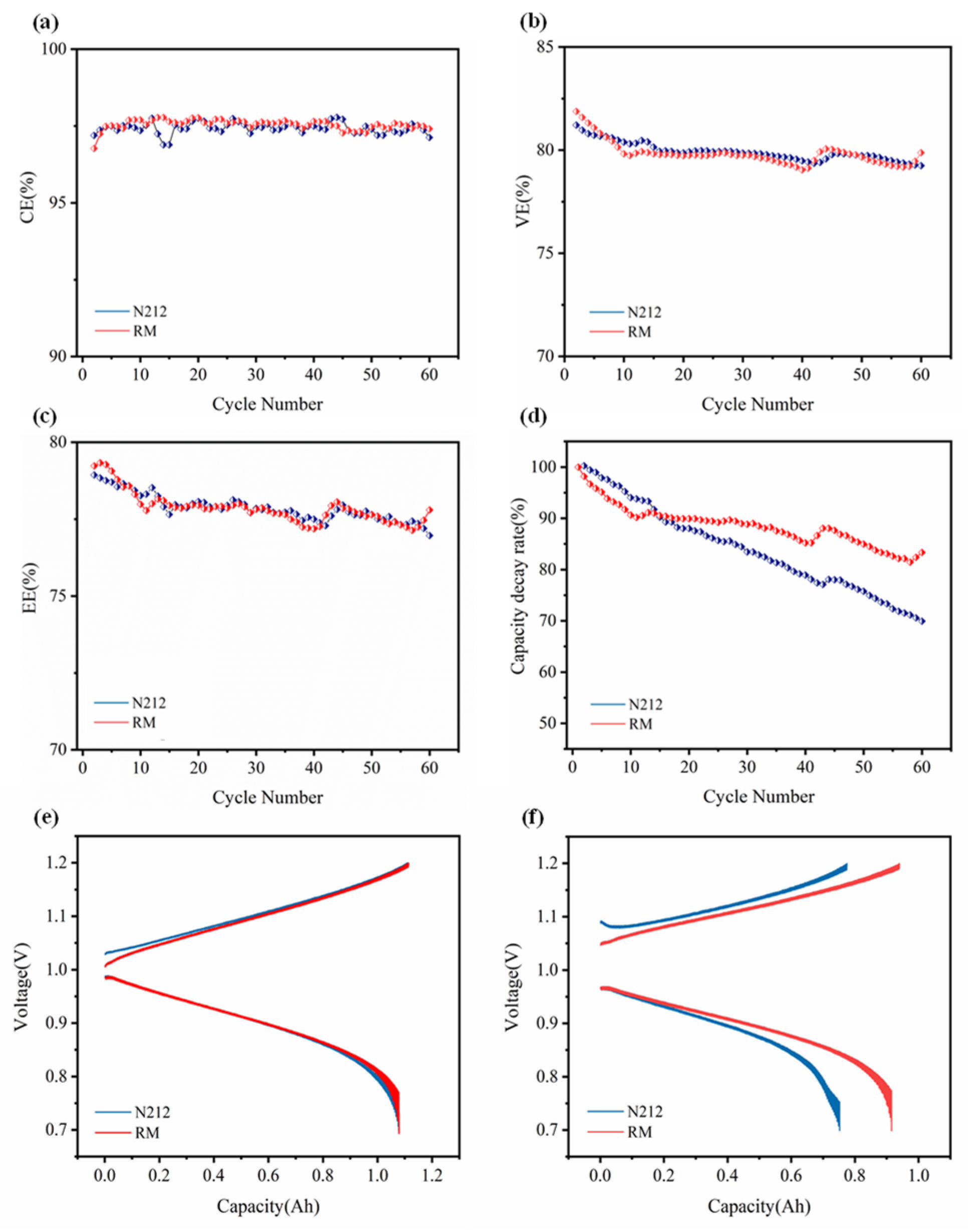
3.2. ICRFB Performance and Stability of the Membrane

Figure 4a,b shows the setup and a diagram of the operation principle of the ICRFB. The N212 and RM are assembled into ICRFB single cells to verify their operational performance. As shown in Figure 4c, there are significant differences in the charge and discharge curves at current densities of 80 mA cm−2. ICRFB exhibited a higher discharge capacity and a significantly lower charge/discharge overpotential when using RM due to higher electrical conductivity than N212. Also, the excellent charge/discharge performance may indicate that the ICRFB has a better VE, as shown in Figure 4d. VE decreases with increasing current concentration, mainly caused by the additional voltage required for the electrode reaction and the extra electrical energy consumption.
In addition, the CE (Figure 4e) is usually influenced by the material’s structure, morphology, and conductivity. Whereas, at higher current densities, the permeation and side reactions of the electroactive materials of both RM and N212 are lower, the CE value increases with the increase of current intensity. EE is the crucial process to estimate the efficiency of the ICRFB system for energy resource utilization during the charge/discharge cycle. VE is the determining parameter of EE. Figure 4f shows the EE variation trend with CE and VE. Compared with CE, EE follows the same trend as VE. The RM exhibits optimal ICRFB cycling performance due to the balance of ionic conductivity, metal ion crossover and membrane resistivity.
To further verify the lifetime of the ICRFB, Figure 5 shows 60 cycles of the test for both membranes at a current density of 140 mA cm−2. In the cell performance test, as shown in Figure 5a–c, the CE of the cells assembled with N212 and RM are relatively stable and remain around 98%, while VE and EE decrease slightly. As shown in Figure 5d, the capacity decay rate of the RM is even lower after 60 cycles. After 60 cycles of RM, the capacitor volume decay rate is only 16.67%, which is about 0.28% per cycle. This indicates that during the membrane remanufacturing process, the PFSA chains are structurally tighter and show similar stability to N212, and a lower capacity decay rate in long cycles. From the above cell test data, it is clear that RM has good electrochemical properties and good proton conductivity. Figure 5e,f show the ICRFB constant current charge and discharge curves for the second and 60th cycles at a current density of 140 mA cm−2. The results indicate that RM has a high discharge capacity and a low charge–discharge overpotential after the initial 60 cycles, and can maintain a good battery capacity. As shown in Figure 6, the ions clusters inside the membrane may be closely arranged after heat treatment, providing a good channel for proton transport. By lowering the proton leap energy barrier, the protons can be thoroughly combined with free water to form hydrated hydrogen ions, which is conducive to the diffusive transport of protons within the membrane and improves conductivity (Table S1).

4. Conclusions

In this work, a method for preparing recycled RM was proposed and tested for its performance in ICRFB. Heat treatment alters the PFSA spatial structure, indicating that the RM has a higher electrical conductivity. The RM properties were prepared and tested based on these theoretical results compared to commercial N212. In the battery test, the RM’s VE was 81.36%, and EE was 79.29% at 140 mA cm−2, both of which are improvements compared with N212. In addition, it showed excellent stability in 60 cycles of charge/discharge testing. Recycling and remanufacturing the waste membrane is economical, with broad application prospects in terms of RFB.

Supplementary Materials

The following supporting information can be downloaded at: https://www.mdpi.com/article/10.3390/en15228717/s1, Figure S1: SEM cross-sectional morphology of (a) N212, (b) the remanufactured membrane; Figure S2: EDS elemental mapping of (a,b) N212, (c,d) the remanufactured membrane; Figure S3: The contact Angle of (a) N212, (b) RM with electrolyte. Table S1: Proton conductivity and resistivity of the membrane.

Author Contributions

Conceptualization, Q.X.; writing—original draft, X.C.; writing—review & editing, S.W.; software, C.G.; methodology, Y.N.; formal analysis, R.Z.; visualization, Z.Y.; investigation, Y.Z.; validation, C.X. All authors have read and agreed to the published version of the manuscript.

Funding

This research was funded by General project of Beijing Natural Science Fund grant number 3222018, and Science Foundation of China University of Petroleum, Beijing grant number (2462020YXZZ018, 2462019QNXZ02, 2462019BJRC007).

Data Availability Statement

Not applicable.

Conflicts of Interest

The authors declare no conflict of interest.

References

  1. Argyrou, M.C.; Christodoulides, P.; Kalogirou, S.A. Energy storage for electricity generation and related processes: Technologies appraisal and grid scale applications. Renew. Sustain. Energy Rev. 2018, 94, 804–821. [Google Scholar] [CrossRef]
  2. Ager, J.W.; Lapkin, A.A. Chemical storage of renewable energy. Science 2018, 360, 707–708. [Google Scholar] [CrossRef] [PubMed] [Green Version]
  3. Ravikumar, M.K.; Rathod, S.; Jaiswal, N.; Patil, S.; Shukla, A. The renaissance in redox flow batteries. J. Solid State Electrochem. 2016, 21, 2467–2488. [Google Scholar] [CrossRef]
  4. Chu, S.; Yi, C.; Liu, N. The path towards sustainable energy. Nat. Mater. 2016, 16, 16–22. [Google Scholar] [CrossRef] [PubMed]
  5. Yang, Z.; Zhang, J.; Kintner-Meyer, M.C.; Lu, X.; Choi, D.; Lemmon, J.P.; Liu, J. Electrochemical energy storage for green grid. Chem. Rev. 2011, 111, 3577–3613. [Google Scholar] [CrossRef]
  6. Zhang, B.; Wang, W.; Liang, L.; Xu, Z.; Li, X.; Qiao, S. Prevailing conjugated porous polymers for electrochemical energy storage and conversion: Lithium-ion batteries, supercapacitors and water-splitting. Coord. Chem. Rev. 2021, 436, 213782. [Google Scholar] [CrossRef]
  7. Blakers, A.; Stocks, M.; Lu, B.; Cheng, C. A review of pumped hydro energy storage. Prog. Energy 2021, 3, 022003. [Google Scholar] [CrossRef]
  8. Zhao, P.; Wang, P.; Xu, W.; Zhang, S.; Wang, J.; Dai, Y. The survey of the combined heat and compressed air energy storage (CH-CAES) system with dual power levels turbomachinery configuration for wind power peak shaving based spectral analysis. Energy 2021, 215, 119167. [Google Scholar] [CrossRef]
  9. Rahman, M.M.; Gemechu, E.; Oni, A.O.; Kumar, A. The development of a techno-economic model for the assessment of the cost of flywheel energy storage systems for utility-scale stationary applications. Sustain. Energy Technol. Assess. 2021, 47, 101382. [Google Scholar] [CrossRef]
  10. Zeng, Y.; Li, F.; Lu, F.; Zhou, X.; Yuan, Y.; Cao, X.; Xiang, B. A hierarchical interdigitated flow field design for scale-up of high-performance redox flow batteries. Appl. Energy 2019, 238, 435–441. [Google Scholar] [CrossRef]
  11. Li, X.; Xiong, J.; Tang, A.; Qin, Y.; Liu, J.; Yan, C. Investigation of the use of electrolyte viscosity for online state-of-charge monitoring design in vanadium redox flow battery. Appl. Energy 2018, 211, 1050–1059. [Google Scholar] [CrossRef]
  12. Wu, M.C.; Zhao, T.S.; Wei, L.; Jiang, H.R.; Zhang, R.H. Improved electrolyte for zinc-bromine flow batteries. J. Power Sources 2018, 384, 232–239. [Google Scholar] [CrossRef]
  13. Ekman, C.K.; Jensen, S.H. Prospects for large scale electricity storage in Denmark. Energy Convers. Manag. 2010, 51, 1140–1147. [Google Scholar] [CrossRef]
  14. Wei, L.; Zeng, L.; Wu, M.C.; Jiang, H.R.; Zhao, T.S. An aqueous manganese-copper battery for large-scale energy storage applications. J. Power Sources 2019, 423, 203–210. [Google Scholar] [CrossRef]
  15. Chang, S.; Ye, J.; Zhou, W.; Wu, C.; Ding, M.; Long, Y.; Cheng, Y.; Jia, C. A low-cost SPEEK-K type membrane for neutral aqueous zinc-iron redox flow battery. Surf. Coat. Technol. 2019, 358, 190–194. [Google Scholar] [CrossRef]
  16. Jia, C.; Liu, J.; Yan, C. A significantly improved membrane for vanadium redox flow battery. J. Power Sources 2010, 195, 4380–4383. [Google Scholar] [CrossRef]
  17. Prifti, H.; Parasuraman, A.; Winardi, S.; Lim, T.M.; Skyllas-Kazacos, M. Membranes for Redox Flow Battery Applications. Membranes 2012, 2, 275–306. [Google Scholar] [CrossRef] [Green Version]
  18. Yang, P.; Xuan, S.; Long, J.; Wang, Y.; Zhang, Y.; Zhang, H. Fluorine-Containing Branched Sulfonated Polyimide Membrane for Vanadium Redox Flow Battery Applications. ChemElectroChem 2018, 5, 3695–3707. [Google Scholar] [CrossRef]
  19. Sun, C.Y.; Zhang, H. Investigation of Nafion series membranes on the performance of iron-chromium redox flow battery. Int. J. Energy Res. 2019, 43, 8739–8752. [Google Scholar] [CrossRef]
  20. Kim, R.; Yuk, S.; Lee, J.-H.; Choi, C.; Kim, S.; Heo, J.; Kim, H.-T. Scaling the water cluster size of Nafion membranes for a high performance Zn/Br redox flow battery. J. Membr. Sci. 2018, 564, 852–858. [Google Scholar] [CrossRef]
  21. Viswanathan, V.; Crawford, A.; Stephenson, D.; Kim, S.; Wang, W.; Li, B.; Coffey, G.; Thomsen, E.; Graff, G.; Balducci, P.; et al. Cost and performance model for redox flow batteries. J. Power Sources 2014, 247, 1040–1051. [Google Scholar] [CrossRef]
  22. Odgaard, M. The Use of Per-Fluorinated Sulfonic Acid (PFSA) Membrane as Electrolyte in Fuel Cells. In Advanced Fluoride-Based Materials for Energy Conversion; Elsevier: Amsterdam, The Netherlands, 2015; pp. 325–374. [Google Scholar]
  23. Chen, D.; Wang, S.; Xiao, M.; Meng, Y. Synthesis and properties of novel sulfonated poly(arylene ether sulfone) ionomers for vanadium redox flow battery. Energy Convers. Manag. 2010, 51, 2816–2824. [Google Scholar] [CrossRef]
  24. Kim, J.; Lee, Y.; Jeon, J.-D.; Kwak, S.-Y. Ion-exchange composite membranes pore-filled with sulfonated poly(ether ether ketone) and Engelhard titanosilicate-10 for improved performance of vanadium redox flow batteries. J. Power Sources 2018, 383, 1–9. [Google Scholar] [CrossRef]
  25. Wang, W.; Luo, Q.; Li, B.; Wei, X.; Li, L.; Yang, Z. Recent Progress in Redox Flow Battery Research and Development. Adv. Funct. Mater. 2013, 23, 970–986. [Google Scholar] [CrossRef]
  26. Hu, J.; Yu, D.; Li, T.; Zhang, H.; Yuan, Z.; Li, X. A highly stable membrane with hierarchical structure for wide pH range flow batteries. J. Energy Chem. 2021, 56, 80–86. [Google Scholar] [CrossRef]
  27. Lai, Y.; Wan, L.; Wang, B. PVDF/Graphene Composite Nanoporous Membranes for Vanadium Flow Batteries. Membranes 2019, 9, 89. [Google Scholar] [CrossRef] [Green Version]
  28. Luan, Y.; Zhang, Y.; Zhang, H.; Lei, L.; Hong, L.; Liu, Y. Annealing effect of perfluorosulfonated ionomer membranes on proton conductivity and methanol permeability. J. Appl. Polym. Sci. 2010, 107, 396–402. [Google Scholar] [CrossRef]
  29. Liu, Y.; Wang, H.; Xiang, Y.; Lu, S. The effect of Nafion membrane thickness on performance of all tungsten-cobalt heteropoly acid redox flow battery. J. Power Sources 2018, 392, 260–264. [Google Scholar] [CrossRef]
  30. Ashraf Gandomi, Y.; Aaron, D.S.; Nolan, Z.B.; Ahmadi, A.; Mench, M.M. Direct Measurement of Crossover and Interfacial Resistance of Ion-Exchange Membranes in All-Vanadium Redox Flow Batteries. Membranes 2020, 10, 126. [Google Scholar] [CrossRef]
Figure 1. (a) Schematic diagram of RM preparation process, (b) battery structure schematic.
Energies 15 08717 g001
Figure 2. (a) SEM surface morphology, (b) SEM cross-section, (c) AFM surface morphology, (d) physical image of N212, (e) SEM surface morphology, (f) SEM cross-section, (g) AFM surface morphology, (h) physical image of the RM.
Energies 15 08717 g002
Figure 3. (a) FTIR spectrum of RM and N212, (b) swelling and water absorption of N212 and RM, (c) tensile strength and strain, (d) Young’s modulus and toughness of N212 and RM.
Energies 15 08717 g003
Figure 4. (a) A photograph of the battery, (b) the battery operation schematic. Effect of RM on ICFB performance: second constant current charge/discharge curves at (c) 80 mA cm−2, (d) VE, (e) CE, and (f) EE versus cycle number at different current densities.
Energies 15 08717 g004
Figure 5. Stable performance of ICRFB assembled with different membranes under 60 cycles at a fixed current density of 140 mA cm−2: (a) CE, (b) VE, (c) EE, and (d) discharge capacity retention; (e) second and (f) 60th constant current charge/discharge curves at 140 mA cm−2.
Energies 15 08717 g005
Figure 6. Proton transport mechanism diagram with proton channels for (a) N212 and (b) RM.
Energies 15 08717 g006
Publisher’s Note: MDPI stays neutral with regard to jurisdictional claims in published maps and institutional affiliations.

