Review

Mobilized Thermal Energy Storage for Waste Heat Recovery and Utilization-Discussion on Crucial Technology Aspects

Department of Energy and Fuels, AGH University of Science and Technology, 30 Mickiewicza Ave., 30-059 Cracow, Poland
Energies 2022, 15(22), 8713; https://doi.org/10.3390/en15228713
Submission received: 29 October 2022 / Revised: 14 November 2022 / Accepted: 18 November 2022 / Published: 20 November 2022

Abstract

:
Changes observed in the Polish energy sector, including the demand for and use of heat, require the introduction of appropriate measures aimed at diversifying the available heat sources, increasing the share of renewable and low-emission sources in heat production, and increasing waste heat recovery and its usage. There is an increasing emphasis on issues such as reducing the carbon footprint, reducing pollution, reducing the use of raw materials, reducing waste heat, and improving the energy efficiency of businesses. Increasingly, the question arises—what technologies can be used as an answer to the identified problems and needs. The solution proposed in this publication to support these needs is the use of mobilized thermal energy storage (M-TES) technology. The use of this technology has great potential, but also involves a number of conditions that need to be taken into account when undertaking the design, construction, and use of this type of technology. The primary purpose of this publication is to provide a detailed description of mobilized thermal energy storage technology, together with a discussion of the various practical aspects associated with the design and use of M-TES. Technology was discussed both in terms of application, but also in terms of specific areas. In the first case—step-by-step, from the design stage to the end-of-life stage. In the second case—one area at a time, including: technical, legal, economic, and environmental. The discussion of the technology is preceded by an analysis of the existing solutions presented in this area. The state-of-the-art shows that, despite the growing interest in the subject, there are still a small number of solutions in this area that have been implemented and are in use. The conducted analysis shows that M-TES is a solution with great potential. However, it is necessary to develop it, especially in the technological, as well as economical, areas.

1. Introduction

1.1. Challenges of the Polish Energy Sector

In Poland, we are currently witnessing dynamic changes in the energy sector, including in heat generation and storage areas. There are changing needs and trends in the supply of heat to consumers (both private and business) for space heating and supply of domestic hot water to individual consumers, but also the heat used in buildings with higher demand, such as public buildings and in industry, for example, process heat. The changes are due, among other things, to the requirements imposed on EU Member States, including the need to reduce CO2 emissions. However, this is also related to a number of other challenges that the Polish energy sector is facing. A couple of them are: limited natural resources, rising electricity and heat prices, and environmental considerations, which are receiving increasing attention, as well as the growing public awareness of the use of alternative energy sources and new technologies in the energy sector, which requires the appropriate adaptation of the infrastructure or the development of new technologies with an adequate level of readiness, adapted to Polish conditions and requirements. In addition, Poland’s energy policy seeks independence from imported resources. Moreover, the military operations conducted in Ukraine have reinforced these activities and strive to accelerate the independence of the Polish energy sector from external supplies of those energy resources.
One of the basic documents taking into account the directions of development and planned changes in the Polish energy sector is the ‘Energy Policy of Poland until 2040’ [1], approved on 2 February 2021, as well as its update in March 2022. The document indicates that, among other development directions, Poland will aim to reduce primary energy consumption and increase the share of renewable energy sources (RES) in all sectors, including heating. At the same time, there is growing interest in the possibility of utilizing of waste heat. This is confirmed by the themes of the founding programs held by the National Centre for Research and Development, including New Technologies for Energy (second competition) [2]. One of the areas of the competition—topic T.5.3—was designed to primarily support projects implementing the use of waste heat with the use of a mobilized thermal energy storage. This is an area which is currently not yet well-known or sufficiently developed in Poland. However, it has great potential, in the context of supporting measures to reduce primary energy consumption. This is also visible in the analysis of the state of the Polish district heating sector.

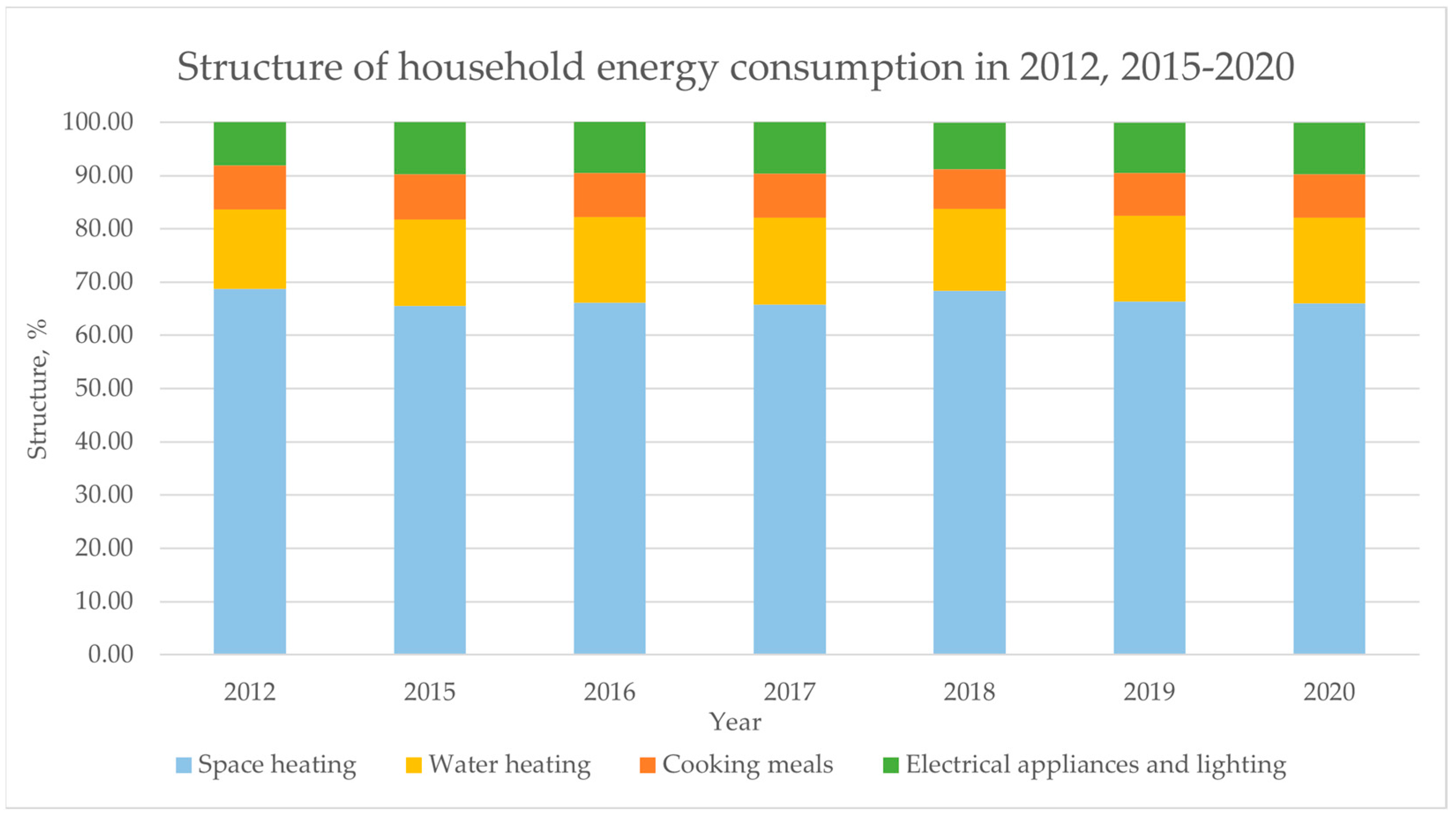
1.2. Polish Heating Sector

Poland’s situation in the heating sector was presented in the Energy Regulatory Office’s (ERO) most up-to-date report “Energetyka cieplna w liczbach-2020” (Heat energetics in numbers-2020) [3], which was issued in February 2022. It shows that, as of 21 December 2020, 387 companies held licences issued by the President of the ERO to carry out generation, transmission, and distribution activities, as well as heat trading. This was a total of 797 for a given type of activity (generation, transmission, and distribution or heat trading). Ninety percent of the district heating companies surveyed were engaged in heat generation in 2020. In total, they generated 393,800 TJ of heat. After accounting for transmission losses and heat consumed for their own use, 57% of the heat generated went to grid-connected consumers. In addition, report [3] provides information on the type of fuels used to produce heat in 2020. The analysis shows that hard coal was used the most. It was used to produce 285,345,066.45 GJ, which is 67.72%, thus the vast majority of the fuels used. This was followed by biomass (41,548,379.86 GJ, or 9.86%) and high-methane natural gas (36,257,839.32 GJ, or 8.60%). A detailed breakdown is presented in Figure 1.
Another document that summarizes the current structure of the heat supply, in this case to residential consumers, is the “Household energy consumption 2018” report. [4]. This is the most up-to-date publication in this area, issued on 23 January 2020. The analysis shows that solid fuels (in the case of single-family houses) and district heating (in the case of multi-family buildings) were used most frequently in space heating. Solid fuels were used by 45.4% of households, and district heating was used by 40.4% of households. In third place was natural gas, which was used by 14.0% of households. The main fuels used for water heating were: district heating (31.6%), natural gas (26.0%), electricity (23.9%), and solid fuels, mainly hard coal (22.44%). Solar energy and heat pumps accounted for a small share of the energy carriers used by households in 2018. A detailed analysis is presented in Table 1.
However, it should be mentioned that the year 2021 brought many changes related to the modernization of heating systems and the orientation of users towards the use of gas and RES, which will only become apparent in the next Central Statistical Office (CSO) report. These changes are due to the support systems in place in Poland, primarily the Clean Air Programme. According to the data available on the website of the Clean Air Programme, updated weekly every Tuesday, during the call period from 19 September 2018 to the last update on 29 July 2022, the total of all heat sources listed with the support of the programme was 401,517. Among the heat sources listed, as many as 41.64% were condensing gas boilers. Air source and ground source heat pumps came second, with a total of 21.22%, of which air source heat pumps accounted for 17.64%, and ground source heat pumps accounted for 3.58% of all heat sources. This was followed by support for the installation of biomass boilers (20.72%), coal boilers (14.29%), electric heating systems (1.67%), district heat systems (0.32%), and oil boilers (0.14%).
When analysing the use of heat in Poland, especially in terms of the possibility of using alternative methods to supply heat to users, it is worth highlighting the areas with the highest heat demands. According to data from the publication: “Consumption of fuels and energy carriers” of the Central Statistical Office [5,6,7,8,9,10,11,12,13,14,15,16,17,18,19], most heat is consumed by industry and construction. In 2020, heat consumption in this sector accounted for 56.1% of total heat consumption. Households are the second largest consumers of heat. Here, heat consumption accounted for 34.5% of total heat consumption. Total heat consumption in 2020 was 441,134 TJ, including 247,392 TJ in industry and 152,270 TJ in households. Additional information is presented in Figure 2.
As indicated above, the largest volumes of heat are consumed by industry and construction. This is a highly differentiated sector, both in terms of the use of heat and the requirements (parameters) that the supplied heat must meet. At the same time, industry is also a source of large amounts of waste heat. A significant number of industrial processes generate large amounts of waste heat that are not managed. Heat transported through the medium at temperatures as high as 1000 °C is often lost. Waste heat recovery allows for the efficiency of the plant to be increased by returning it to the system and using it. Such a system is not always economically justifiable, especially at lower temperatures, below 120–150 °C. However, these are ideal conditions for storing heat and using it elsewhere through M-TES applications. Among the industrial plants that can act as a heat source for M-TES are: incineration plants, glass works, aluminium factories, drying plants, coking plants, cement works, and foundries. If M-TES is used, the waste heat could be partially used for the plant’s own needs and partially for the needs of consumers, including individual consumers for central heating and domestic hot water. According to data from the Central Statistical Office, presented in the document: “Efficiency of energy use in 2010–2020” [20], published on 29 June 2022, in households, energy consumption for space heating purposes accounted for 66% in 2020. For water heating purposes, it was 16.1%, which, in total, accounts for 82.1% in the entire structure of energy consumption in households and remains above 80% in the analyzed years 2012–2020. Figure 3 shows a detailed breakdown of the energy consumption of households in 2012–2020.

1.3. Potential Direction of Development

The above-mentioned information indicates that the measures carried out in Poland will aim to reduce primary energy consumption and increase the share of RES in all sectors, including heating. At the same time, they will aim to become independent from imported energy resources. It should be noted, however, that when analysing the current situation, it is noticeable that Poland faces major challenges. The data quoted clearly indicates that, in Poland, fossil fuels continue to be the primary energy carrier, with hard coal playing the largest role. In this situation, it is necessary to implement not only currently available solutions, but also new, pro-ecological technologies, based on renewable energy sources and waste heat. For this reason, the author has focused in this publication on M-TES technology, which fits perfectly with the identified needs. The subject of M-TES, especially using PCM, is currently under intensive development and is part of a large area, which is constantly enriched with new knowledge. The knowledge is related to M-TES, but also to nearby topics, such as improving the properties of PCM [21], improving the efficiency of the phase transformation process, and improving the design of heat storage [22,23,24]. The assumptions for using M-TES solution are described in detail later in the publication. The main objective of the work presented in the following sections of the article is to analyze the M-TES technology in detail and answer the questions:
  • What is M-TES technology, and under what circumstances can it be applied?
  • What conditions must be met for the use of M-TES to be justified?
  • What are the most important technological areas of M-TES?
  • Does the application of M-TES have potential in Polish conditions?

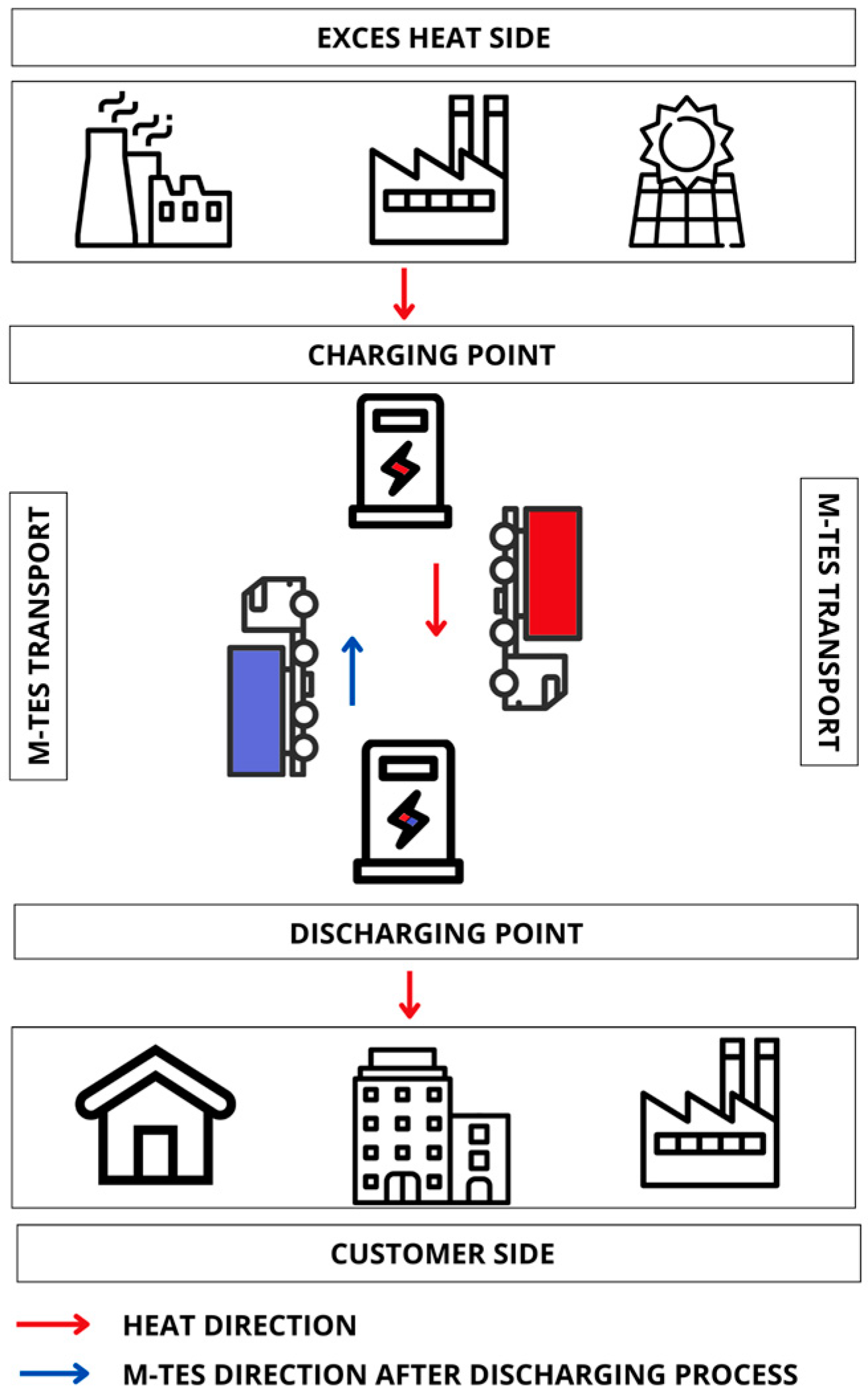
2. Mobilized Thermal Energy Storage-Operating Principle

Mobilized thermal energy storage is a technology that can be used to provide heat to various types of consumers: from individual consumers (single-family homes), through multi-family buildings, office buildings, service and public buildings, and industrial consumers. Thus, the heat supplied can be used for a variety of purposes, including space heating and domestic hot water, but also more specific applications, such as the heating of swimming pool water or production and industrial processes—especially those that do not require high temperatures.
In many cases, mobilized thermal energy storage can be considered as an alternative to classic heat supply solutions, such as the use of heat pipelines or the use of individual boilers. In the first case, the M-TES will primarily be used where the construction of a heat pipeline is not cost-effective or is not justified or possible, due to technical considerations. In addition, the amount of heat available must be taken into account. For sources with small amounts of heat available on an irregular basis, the construction of a heat pipeline may also not be justified. In the second case—the use of M-TES may avoid the investment costs associated with the construction of boiler rooms, but more importantly, reduce emissions at the point of use of the heat, especially if it replaces a coal-fired boilers.
The basis of mobilized thermal energy storage technology is based on the use of heat at a location other than its source (production). This is achieved through the use of a suitably designed M-TES container, which is suitable for transport and usually transported by road. The size, design, amount of heat storage, method of transport, and other important aspects can be individually designed and adapted to the system in which the M-TES will operate. These aspects are discussed in detail in paragraph 4.
A mobilized thermal energy storage system, in practice, consists of:
  • Thermal energy storage unit: a tank equipped with a heat exchanger and filled with a working material (capable of storing significant quantities of thermal energy), e.g., a phase change material (PCM), supplemented by plant components allowing the heat to be transferred to/from the storage.
  • A control and measurement system that will enable the status of charge/discharge of the storage to be monitored and the course of its operation to be observed.
  • A transport system enabling the storage to be transported (independent or permanently integrated transport system).
  • Connection points at the point of charging (at the heat source) and storage discharge (at the heat consumer).
A M-TES is used to store, keep, and release heat at a specific time and location. It is designed to be transported for use at various locations, which are, by definition, a few, a dozen, or even several dozen kilometres away from the heat source. The process of using M-TES takes place in several stages, including: the loading stage of the storage, transport (usually by road), and the gradual unloading of the storage at the user’s site, adapted to demand. The transport distance is most often determined by economic considerations. A key role in this technology is played by the heat storage substance, usually a phase change material, which is characterized by its ability to store significant amounts of heat per unit. This is possible through the use of both sensible and latent heat, with a significant proportion of latent heat.
The use of the storage follows the diagram presented in Figure 4, with the assumption that, for the optimum use of the technology, two storages should operate in parallel in each system. While the first is at the customer, the second storage is loading or ready for delivery to the customer before the first storage is fully unloaded. This is essential if the M-TES is to be used to supply the amount of heat required to fill the full heat demand of the customer. It will then work as the primary (often only) heat source. However, the use of the M-TES as a supplementary or emergency source also comes into play. In the first case, the system in primary mode will be supplied by another heat source, but it will be possible to switch on the M-TES, depending on the consumer’s demand and/or the availability of heat supplied by the M-TES. In the second case, heat will only be supplied in the event of an emergency. This will apply to customers who, for various reasons, cannot allow the heat supply to be interrupted.

3. Mobilized Thermal Energy Storage-State of the Art

The topic of M-TES technology is becoming increasingly popular. However, it should be noted that the amount of research or deployments carried out in this area shows that this technology is still in the development stage. It is not widely available. A careful analysis makes it possible to identify the areas in need of development, as well as those with the greatest potential, related, among other things, to the specific consumer or heat source. Table 2 presents a summary of identified solutions available commercially (commercial), investigated in research projects, at various stages of readiness for implementation (lab research or pilot research), and solutions at the stages of analysis: theoretical (theoretical), numerical (numerical), or economic analysis (economical). The different M-TES systems are indicated in the table analogous to the designations in brackets.
The first two positions are occupied by companies offering M-TES solutions in Poland. Enetech sp.z.o.o. [25] offers a PCM-based M-TES weighing 24 t and storing approximately 7 GJ of heat, with a maximum tank discharge capacity of 150 kW. The system offered by Enetech sp. z o.o., uses two tanks operating in parallel to ensure the continuity of supply. While the first is in use by the customer, the second is charged at the heat source and then transported to the customer to swap them with each other at the appropriate time. Among other things, the storage facilities offered by the company can be used to store waste heat. The company indicates on its website (https://enetech.com.pl/, accessed on 28 October 2022) that approximately 60 TWh of waste heat is lost annually in Polish industry, mainly low-temperature heat, below 220 °C.
The second company Neo Bio Energy sp. z o.o., [26], does not provide details of the solution offered on its website. They only indicate that the mobilized thermal energy storage unit can make it possible to manage waste heat from combined heat and power generation.
The Pacific Institute for Climate Solutions, with the City of Surrey and Canmet ENERGY, launched a project on 1 September 2019 to develop a prototype of mobilized thermal energy storage [27], powered by waste heat, for use in municipal energy systems. The project took three years to complete. The project opted for a mobilized heat store, based on a thermochemical liquid sorption system. The use of M-TES, in this case, aims to reduce the use of classical energy sources and reduce greenhouse gas emissions. A study [28] analyzed the use of M-TES from technological, economical, and environmental perspectives. The authors considered three transportation methods (a diesel truck, a renewable natural gas-powered (RNG) truck, and an electric truck) to determine the most cost-effective and low-carbon option to transport heat from industrial waste heat locations to district energy networks. They considered three various distances: 15, 30, and 45 km. The authors compared effects to their current system, which is a natural gas boiler to the systems considered for the future, which are: RNG/biomass boiler, sewer heat recovery, electric boiler, and solar thermal. The authors’ analysis shows that, for an M-TES to be competitive, it must be able to store at least 0.4 MJ/kg. For the case study, it was determined that an M-TES of 10 tonnes, capable of carrying 0.7 MJ/kg, with a fixed schedule of six trips/day, operating 360 days/year, would meet 7% of the grid demand set for 2022. In addition, it was indicated that using RNG or electric trucks would allow for the cost-effective transportation of M-TES in the 15–50 km range. If a diesel truck is used, the transport should not be for more than 30 km.
The trans-heat container (THC) [29] is a joint project between Germany and Japan. Three M-TES were built as part of the collaboration. Two of them were tested in Japan and one in Germany. At the initial stage of the work, all the conditions specific to both locations were analyzed, including: heat demand, climate, terrain, infrastructure, and legal aspects. The storage tested in Germany was designed as a low temperature 30 t storage. The material used in this solution was sodium acetate trihydrate-PCM, with a phase transition of approx. 58 °C and heat of conversion of 230 kJ/kg. It was assumed that the heat source must have a heat of at least 70 °C, optimally above 90 °C. As part of the same project, two M-TESs were tested in Japan. The first, with a mass of 24 t, used the same PCM that was used in Germany. The second M-TES was based on the use of erythritol, of which phase transformation occurs at a temperature of approximately 118 °C and has a heat of phase transformation of 340 kJ/kg. It was assumed that the heat source must have a heat of at least 130 °C, optimally at least 150 °C. In this case, a modular solution was used, where a container with a total weight of 10 t was made up of four smaller units. This storage unit was tested not only for use for central heating and hot water but also for cooling (through the use of an absorption refrigerator).
LaTherm [30,31,32,33,34,35,36] is an M-TES on which work has continued intermittently since 2009. The solution was designed as a 29-tonne container (with a volume of 17 m3, with an internal heat exchanger embedded in PCM). Sodium acetate was used as the PCM. In the first stages of testing, the heat source was waste heat from a biogas plant and from industry. Initially, the heat was used for heating purposes (central heating, hot water). However, due to the low temperature of the stored heat, 58 °C, it was decided to use the storage facility to heat water in an outdoor swimming pool, i.e., to maintain the water temperature at around 20 °C, which was a much better solution. At this stage, however, no decision was made to implement the solution on a larger scale. The main problem with this M-TES was the lack of cost-effectiveness of the solution. It involved a high cost, while at the same time, a low amount of stored heat. The solution was not competitive enough, e.g., compared to trucks carrying heating oil. The project was taken up again in 2018 in Hanover. In this case, the heat source is a landfill site, and the transport is carried out over short distances using an electric truck. The recipient of the heat is a school.
Weilong Wang et al. [37] carried out a laboratory study to test different solutions for a mobilized thermal energy storage that would be applicable to the management of waste or excess heat. The laboratory-scale work compared different solutions, both a direct contact TES container and indirect contact TES container. Erythritol was chosen as the working material, while thermal oil was used as the PCM melting agent. From the tests carried out, it could be seen that, with the direct contact container, in the initial stage, the loading of the storage was hampered, because the access of the oil to the container and the distribution of the oil inside the storage was blocked, due to the unmelted PCM. The situation improved with loading time—once the oil formed corridors inside the solid PCM, the heat was distributed. It took the longest time for the PCM to melt at the bottom of the storage and near the external walls. The regulation of the heat transfer fluid (HTF) flow affects both the charging and discharging processes. An increase in flow improves the process. For the indirect contact container, the charging and discharging processes proceeded at similar rates. Additionally, no effect on the charging/discharging process was observed by changing the HTF flow rate. The comparison of the two solutions showed that the rate of charging and discharging can proceed faster when using a direct contact container. The low thermal conductivity of the PCM, which significantly impedes the heat distribution in the system, was identified as a significant problem, especially when using an indirect contact container. The study also showed that the erythritol phase transformation process has a wide temperature range.
Yan Wang et al. [38] conducted a laboratory study to test a new heat storage design dedicated to a M-TES application. The authors assumed that the stored heat could come from renewable sources or industrial waste heat. The heat storage unit in the tested system was a heat exchanger consisting of tubes filled with PCM. A phase change material was filled into 80 stainless steel tubes. This heat exchanger arrangement increases the heat transfer surface area, but involves a large expansion of the heat exchanger and an increase in mass and volume. Heat transfer fluid filled the heat storage, and the heat exchanger was immersed in it. In the test storage, the sodium acetate was used as a PCM. It was used in the amount of 215 kg. The tests carried out demonstrated the ability to store 125,576 kJ of heat, which was achieved in one hour. The discharge time was longer. The tests showed that, during the charging process, the PCM melted unevenly. The PCM located in the central part of the exchanger heated up faster, while at the ends of the tubes, the temperature increased slowly. During the discharge process, large differences were observed in the patterns of temperature change inside the individual tubes. In the case of those distant from the cold water inlet, supercooling occurred. The authors observed the occurrence of a phase transition stage in the course of the process, characteristic when using PCM. It was found that the stored heat was not released 100%, and the efficiency of the designed system for latent heat was estimated at 79.4%.
Andreas Krönauer et al. [39] presented the results of a one-year test of a mobilized thermal energy storage system. The system was based on the use of zeolites. The MTES contained 14 tonnes of zeolite. The role of the heat source was played by a waste incineration plant, where extraction steam was used. This enabled the storage to be charged with hot air at 130 °C. The heat receiver was the dryer, 7 km away from the heat source, where heat was received at a temperature of 60 °C. The storage facility provided a heat supply of 2.3 MWh. However, the desired discharge capacity was not achieved. The authors emphasized that, when using zeolite, it is extremely important to select a heat source with a temperature above 130 °C. Another aspect addressed is also the need to select a heat consumer with a year-round heat demand. This is related to economic considerations and the speed of the return on investment.
Xuelai Zhang et al. [40] proposed in their work the use of capsules in M-TES system. The technical solution focuses on the use of spherical capsules and placing them in the heat storage. The balls are made from stainless steel with a 2 mm wall thickness, with radii of: 60 mm, 80 mm, 100 mm. The capsules were filled with a new PCM, which consists of 99.6% erythritol and 0.4% nanocopper. The use of the nanocopper additive enhanced the thermal conductivity up to 3.3 times, compared with pure erythritol. Experimental work and mathematical analysis of the proposed solution were carried out. Similar results were obtained for the experimental work and the mathematical analysis. This allowed a number of conclusions to be drawn. The dimensions of the tank, which was filled with balls, were 4.1 m × 2 m × 1.25 m (outer dimension) and 3.6 m × 1.8 m × 1.1 m. The space between the outer and inner layers contains thermal insulation. The role of heat transfer fluid, in this case, was played by thermal oil. During the heat storage process, the HTF had a temperature of 180 °C, which is about 60 °C higher than the phase transformation temperature. The initial temperature of the HTF had a very strong influence on the heat transfer process in the storage discharge process. The process was tested for HTF, with temperatures of 60, 40, and 30 °C. The use of 40 °C and 20 °C temperatures resulted in reductions in phase transformation time of: 30.28% and 48.88%.
Takahiro Nomura et al. [41] analyzed the feasibility of a PCM-based mobilized heat transport system for use in receiving heat above 300 °C from steelworks and transporting it for use in a distillation tower of benzene, toluene, and xylene. Three alternative systems were compared with each other. The first was a conventional system that uses the combustion heat of a coke oven gas on site to obtain hot oil at 250 °C. The second system was a sensible heat transport system, which works by transporting heat stored in sensible form. The medium used to heat and store the heat is oil. The third system analyzed was a latent heat transportation system. In this case, it was proposed to use a system based on PCM, which stores heat. NaOH was proposed, in which phase transformation occurs at 293–320 °C. The circulating medium in the system, responsible for heat transfer, is oil. The storage was transported over a distance of 10 km. The authors presented the results of the analyses, emphasizing that the use of system 3 not only enabled the use of waste heat, but also had the effect of reducing fossil fuel consumption and CO2 emissions. System 3 provided the largest amount of heat (8.15 GJ in 250 °C). This was as much as 2.76 times more than for system 2. System 3, compared to system 1, had significantly lower energy requirements (8.6% of system 1 requirements), lower exergy losses (37.9% of system 1 losses), and lower CO2 emissions (17.5%, compared to system 1).
J.NW. Chiu et al. [42] presented a paper consisting of three areas on mobilized thermal energy storage: MTES design (material selection—PCM: 99% pure erythritol and heat exchanger design—shell and tube type heat exchangers), environmental evaluation, and economic analysis. The analysis used a case study in Sweden for a district heating network located at 48 km from the heat source. The authors examined three alternatives for transporting the heat store: road, rail, and maritime. From an economic perspective, an optimized operational strategy was carried out to maximize the economic viability of the project. The authors determined the proposed project to be feasible. The model showed a non-linearity in the run, where for up to 60% of the storage level there was fast loading and unloading, while after that, the loading and unloading rate decreased exponentially. To optimize the cost-effectiveness of the solution, the authors indicated that the number of runs and the number of M-TES units used should be minimized. The results for M-TES and for the district heating network were summarized. When dealing with the transport of large volumes of heat for fixed locations of both heat sources and heat consumers, the district heating network performed more favourably. However, when the flexibility of the supply was required, M-TES showed a strong advantage. The authors also identified that one of the most important parameters that the system should have is the rate of storage loading/unloading, which is especially necessary for large heat loads. It was pointed out that, with the increasing price of conventional heat supply methods, M-TES using waste heat could prove to be a solution with great economic potential. The transport methods analyzed were feasible. However, attention should be paid to potential technical problems, e.g., associated with water transport and possible water freezing in winter or the lack of access to water reservoirs and the need to substitute another transport method. The environmental assessment of CO2 emissions from transport indicated that, compared to conventional boilers using LPG/Diesel fuel oil with CO2 emissions of 136 kg/MWhth to 216 kg/MWhth, in the case studied, M-TES only resulted in up to kg/MWhth to 150 kg/MWhth of CO2 emissions, depending on the mode of transport and the user’s heat demand profile.
Shaopeng Guo et al. [43] focused their work on the fundamental problem identified with the direct contact mobilized thermal energy storage container. The problem analyzed relates to the blocking of the heat distribution process in the container during the initial stage of the charging process by the solid PCM and, thus, the melting of the PCM. The heat transfer fluid, which, in this case, is thermal oil, has an obstructed path to enter the storage through the solidified PCM at the initial stage. In order to prevent this, the authors analyzed the effects of using electric heaters to create ‘quick channels’ to streamline the phase transition. Analogous systems with and without the use of heaters were compared. The authors showed that the use of their proposed solution shows great potential and eliminates the aforementioned HTF flow blockage problem. The solution works all the more well for systems where the flow rate is low and the heat demand is not high. This is due to the impossibility of using high HTF flow. It is not always possible to increase the HTF flow, as the value is based on the instantaneous heat demand. In addition, the use of high flows may involve a partial loss of PCM from storage. The use of heaters involves the additional energy consumption. However, it should be noted that, in the tests conducted, this only accounted for 5% of the stored energy, and as the authors indicated, with M-TES operating under realistic conditions, a larger scale of storage will reduce the proportion of energy used.
Numerous authors undertook numerical studies aimed at improving the operation of PCM-based heat stores—both mobile and stationary. A selection of numerical works focusing on M-TES are cited in the following text.
Shaopeng Guo et al. [44] referred, in their work, to the research presented in [34]. The authors developed a two-dimensional numerical simulation model in ANSYS FLUENT to analyze and improve the charging performance of the direct contact M-TES system. The model was verified by experimental measurements. The model was used to investigate the different options for reducing the charging time, including by increasing the thermal oil flow, creating channels in the PCM before charging the storage, and by adding wall heating. The results of the analysis show that it is possible to reduce the charging times by, respectively: 25%, 26%, or 29%. It was also indicated that the simultaneous application of the last two options could reduce the charging time by more than half, without changing the thermal oil flow rate.
In a subsequent paper by Shaopeng Guo et al. [45], they aimed to improve the efficiency of the charging process of an indirect contact mobilized thermal energy storage container and to better understand the phase transformation phenomenon during the processes involved in heat storage operation. For this purpose, they developed a two-dimensional (2D) numerical simulation model in ANSYS FLUENT. The model was validated by the experimental measurements. Based on the results, it was indicated that the model could be used in the analysis. The work compared three options: the addition of expanded graphite, which has a high thermal conductivity, a change in pipe diameter, and the use of an expansion of the internal structure of the store by using fins. All measures were aimed at improving the heat transfer inside the TES unit, thereby improving the phase change and charging/discharging of the magazine. The authors showed that the most effective solutions for the three options are the use of 10% of volume expanded graphite, a heat exchanger with a tube diameter of 22 mm, and fins of 0.468 m2. When all three options are used at the same time, there is a big difference in the time it takes to load and unload the storage. The charging time is reduced by 74%, while the discharge time is reduced by 67%.
In their work, Zhan Liu et al. [46] highlighted the importance of improving the phase transformation performance of PCMs used in heat storage, including mobile applications. The authors analyzed the impact of using a novel ladder-shaped fin to accelerate the melting process. For this purpose, two groups of fin shapes were designed and studied, with a total of eight different cases. In the first group, the fins were arranged vertically and horizontally, with respect to the axis, while in the second group, they were arranged at an angle of 45°, with respect to the axis. The design assumes that, regardless of the design of the ribs, they have equal mass. The numerical models developed by the authors were verified by the experiments in the literature. The results of the analyses confirmed the authors’ assumption that the use of ladder-shaped fins would accelerate the phase transformation, compared to straight fins. It is possible to reduce the time by up to 52.2%. The authors indicated that each option proposed in group I was more beneficial than the corresponding option in group II. In contrast, the use of ladder-shaped fins was beneficial for both groups, as it resulted in a reduction in melting time of 38.3% for group II and 24.4% for group I. Given the assumption of using the same mass of material, regardless of the type of fins (and, thus, no effect on the change in mass of the entire container), the use of ladder-shaped fins appeared to be a reasonable solution.
Another example of numerical analysis for mobilized thermal energy storage is the work of Ismail Gürkan Demirkıran et al. [47]. The authors highlighted two important aspects. The first—the need to improve the thermal conductivity inside the heat store, necessary for the efficient charging and discharging of the heat storage. The second—concerning the need to reduce the investment costs of mobilized thermal energy storage systems, in order to improve their competitiveness. To this end, the authors developed a model to test the impact of innovative fin structures on the melting performance of PCMs, while assuming no increase in capital costs. Two-dimensional phase change models for shell-and-tube heat exchangers were simulated. Analyses were carried out for different numbers of fins (2, 4, and 6) and different fin structures (straight and branched). Changes were observed for the PCM melting process over 30 min, using a constant HTF temperature. The authors indicated that, contrary to the results presented in the literature, they observed that the ribs located in the upper part of the tube responsible for distributing the HTF inside the magazine gave better results. The number of ribs influenced the melting efficiency. When increasing the number of ribs from two to four, there was an increase of 15.8%. On the other hand, a further increase to six ribs had the opposite effect, and the melting rate decreased below the effects for the four-rib arrangement. The authors emphasized that the analysis showed that the use of a change in the rib structure can improve the heat distribution inside the storage, and at the same time, this does not necessarily increase the investment costs or the total volume of the storage.
The tests carried out so far, both on a laboratory scale and in real-life conditions, have allowed the various research groups to identify similar advantages and challenges in the application of mobilized thermal energy storage. Among other things, a great deal of attention has been paid to the economic analysis of the various solutions. Publications developed in this area are presented in the following section.
In their work, Shaopeng Guo et al. [48] analyzed the use of mobilized thermal energy storage powered by waste heat, supplying residential consumers in the form of small and medium-sized residential buildings. The analysis was carried out from a technical and economic perspective for China in 2016. The authors concluded that this type of heat supply would perform much better for heating systems using fan-coil units or under-floor pipes than for systems using radiators. The authors included road transport regulations in their analysis, which led them to determine a maximum container weight of 39 t. In the cost-effectiveness analysis, the authors assumed that the building supplied with heat has a heating demand of 24 h a day. It was also assumed that an additional cost of 50% applies for night-time operation, in line with current law and policy. A government subsidy for the use of waste heat, of 0.91 × 10⁴ euro/year, was also taken into account. After taking all assumptions into account, and in order to assess the most cost-effective number of heat transport cycles per day (4, 6, or 8), an NPV and PBP analysis was carried out. The analysis indicated the possibility of achieving cost-effectiveness after 10 years of operation of the M-TES, assuming the use of the most cost-effective daily cycle, i.e., four transport cycles per day.
Jing Yang et al. [49] highlighted, in their work, the differences in classical heat recovery and management, compared to a mobile system. The authors emphasized the role of economic and environmental analysis in the design and application of M-TES. In their work, the authors proposed an analytical model to analyze and evaluate the economic effects of investigating a waste heat supply chain system using M-TES. The proposed model also aimed to optimize for economic and environmental benefits. The results of the analysis indicated that, in order to achieve optimal system operating conditions, it is necessary to plan the heat production (recovery) appropriately. It is crucial to not create a situation of overproduction or underproduction. This is because, in a situation of waste heat recovery or M-TES capacity constraints, the priority is to meet the needs of the consumers, and the aspects mentioned earlier directly affect the cost-effectiveness of using M-TES. The authors’ analysis indicates that, using waste heat at a rate of 3.78 × 10¹⁰ kJ/year to heat water in the temperature range 20–70 °C, it is possible to eliminate the consumption of 1290 t of coal and introduce savings of USD 216,929.28 per year. The authors emphasized that limitations have been applied to the analysis, and further research is required to consider a number of elements in the future. An increase in the popularity of waste heat recovery and its utilization and an increase in heat capacity in M-TES are needed to increase cost-effectiveness and support economic feasibility. The publication cites data highlighting how small the share of the real usage of primary energy. For the United States, only 31.1 percent of primary energy is converted into usable energy, while 66.7 percent is wasted as waste energy. The authors also highlighted the need for a more comprehensive analysis of real-world use cases of M-TES in waste heat management to encourage the introduction of new forms of government subsidies in this area. The provision of appropriate subsidies is, according to the authors, an opportunity to reduce the payback period and increase the profitability of M-TES applications.
Shaopeng Guo et al. [50] conducted an economic analysis for an M-TES system used in China to supply heat to distributed users. They assumed the use of two M-TES, operating in parallel. The authors pointed out that the assumptions for the construction of the storage must take into account the current regulations and limits applicable to road transport. In China, the maximum load of vehicle, including the transported cargo, trailer, and the vehicle itself, is 49 t. The effects were analyzed for two, three, four, six, and eight M-TES trips per day. The options with two or three passes were discarded for reasons related to the need to provide certain amounts of heat. After further economic analysis of the remaining options, it was shown that six passes were the most justifiable and, depending on the waste heat price adopted (0, 3300 or 6600 Euro/MWh), the investment would pay for itself within 2, 3, or 5 years.
In their work, Hailong Li et al. [51] conducted an economic evaluation of the operation of the M-TES system and identified the key elements influencing the economic viability of its application. The authors estimated in their analysis that the cost of heat supplied from the M-TES unit at USD 0.03–0.06/kWh. The main factors identified as having the greatest impact on cost were heat demand (inversely proportional change) and transport distance (proportional change). Further factors with a high impact on changing perceptions of the cost-effectiveness of M-TES were the initial investment cost (primarily the cost of PCM, and this factor in the sensitivity analysis shows the greatest impact on cost-effectiveness), transport cost, or system lifetime. In their analysis, the authors showed that there is a relationship between the minimum heat price and the maximum amount of heat that can be delivered to the consumer. For example, for a distance of 10 km, a minimum price of about USD 0.011/kWh was indicated. The authors also indicated that, compared to classical heat supply systems, M-TES performs better for shorter transport distances. For example, for a certain group of customers, switching from a biogas system to M-TES gives a payback time of 5 or 8 years, depending on the transport distance—10 or 30 km from the heat source. Water also appears in the analysis as a substitute for PCM. However, here it should be noted that the use of water offers the possibility of storing smaller amounts of heat than, for example, the use of erythritol. Therefore, it can only be considered for transport over shorter distances or to consumers with lower heat demands.
Marco Deckert et al. [52] presented in their paper an analysis of the technical and economic feasibility of the M-TES system developed and tested at Fraunhofer Institute for Environmental, Safety, and Energy Technology. The authors point out that the cost-effectiveness of the system is highly dependent on the thermal capacity of the system, but also on the characteristics of the heat consumers—their behaviour, needs, and number of charging/discharging cycles per year. Attention was also drawn to the need for the availability of cheap and unused heat. It is also crucial that charging/discharging times are as short as possible. The authors indicated that they were able to achieve optimum M-TES charging times through a suitable combination of parameter values, such as HTF flow rate, HTF inlet temperature, heat extraction power, choice of construction materials, and heat storage geometry. The use of additive graphitic structures was also identified as a factor that positively influence the phase transformation time. However, it was highlighted that their use significantly increases investment costs.
Table 2. Mobilized thermal energy storage systems.
Level of ReadinessCountry/
Date
MTES Technology/
Heat Storage Capacity
Heat Source/
Heat Recipient/
Distance
References
CommercialPoland/currently
available on offer
PCM/7GJWaste heat/different
types of recipients/
[25]
CommercialPoland/currently
available on offer
PCM/n.a.Waste heat/different
types of recipients/
[26]
Pilot researchCity of Surrey, Canada/2019–2021Thermochemical reactionWaste heat/city energy network[27,28]
Pilot researchGermany, Japan/
2019
PCM/n.a.Waste heat/hot water, heating, cooling[26]
Pilot researchGermany/
Since 2009
PCM/
2.1–2.5 MWh
Waste heat/hot water, heating, swimming pool supply[27,28,29,30,31,32,33,34]
Pilot researchGermany/
2015
Zeolite/
2.3 MWh
Industrial waste heat[37]
Lab. researchChina, laboratory/
2014
PCM/n.a.Excess, industrial waste heat[38]
Lab. researchChina, laboratory/
2019
PCM/
0.000, 125,576 GJ
renewable energy, industrial waste heat[39]
Lab. researchChina, laboratory/
2016
PCM/n.a.Industrial waste heat[40]
TheoreticalJapan/2009PCM/8.15 GJIndustrial waste heat/ chemical plant[41]
Theoretical, design, economical, environmental evaluationSweden/2016PCM/n.a.Industrial waste heat[42]
Lab. researchChina/2015PCM/n.a.Excess, industrial waste heat[43]
NumericalChina and Sweden/2013PCM/n.a.Excess, industrial waste heat[44]
NumericalChina and Sweden/2016PCM/n.a.Excess, industrial waste heat[45]
NumericalChina and Sweden/2022PCM/n.a.Waste heat[46]
NumericalTurkey/Brasil/2021PCM/n.a.n.a.[47]
EconomicalChina/2016PCM/1.35–5.4 MWhWaste heat[48]
Economicaln.a.PCM/n.a.Waste heat[49]
EconomicalChina/2016PCM/1.35–5.4 MWhWaste heat[50]
EconomicalChina, Sweden/2013PCM, water/n.a.Waste heat[51]
Economical, technicalGermany/2014PCM/1.3 MWhWaste heat[52]
EconomicalPoland/2020PCM/55 kWhGeothermal heat[53]
Matuszewska et al. [53] analyzed the economic and technical feasibility of using M-TES for Polish conditions, using geothermal heat as a heat source and assuming heat supply to individual consumers. The analysis assumed the use of an indirect contact TES container filled with PCM, with a phase transition temperature of about 70 °C, in an amount of 800 kg, characterized by a heat storage capacity of 250 kJ/kg. It was assumed that the total heat capacity of one M-TES is 55 kWh and that two storages needs to be operated in parallel to ensure the continuity of supply. The cost per storage was estimated at EUR 6000. The authors indicated that the distance over which the storage will be transported has a very large impact on the cost-effectiveness of using M-TES. For the assumptions indicated, it was concluded that there is no justification to transport geothermal heat over distances greater than 3–4 km from the heat source. It was indicated that an M-TES with the assumed parameters could meet the needs of a building with a heat demand of up to 25,000 kWh/year. It was shown that, for the assumptions quoted, the profitability of the investment was achievable for certain combinations of heat demand, distance, and the price of the replaced heat source. For a heat demand of 5000 kWh/year the price of the replaced heat source is at the level of 0.21 EUR/kWh, with a transportation distance of 0.5 km. For a heat demand of 15,000 kWh/year, the price is EUR 0.11/kWh, and the distance is 0.5 km. For a demand of 25,000 kWh/year, the price is EUR 0.085/kWh, and the distance is also 0.5 km. The NPV value for M-TES was determined for 20 years.
It is also worth mentioning the review papers that has been written in the area of mobilized thermal energy storage. The authors undertook analyses from a variety of perspectives. Q. Ma et al. [54] focused on analysing different methods potentially suitable for transporting heat over longer distances. For high temperatures, chemical catalytic reversible reactions, and for lower temperatures, corresponding to the most commonly available waste heat, chemical reversible reactions, phase change thermal energy storage and transportation, hydrogen-absorbing alloys, solid–gas adsorption, and liquid–gas absorption. M. Nemś et al. [55], in their work, focused on discussing the general principle of M-TES. In this case, phase change materials, zeolites (as a representation of sorption materials), and oil were cited as working substances for heat storage. The authors analyzed which factors could increase the applicability of the M-TES systems in practice, both economically and technically. In addition, the publication proposed a method for recharging the transported battery with waste heat from the internal combustion engine, with the aim of eliminating the losses that occur during the duty cycle. Laia Miró et al. [56] focused their work on the potential and feasibility of utilizing industrial waste heat. Among the solutions, M-TES technology was indicated. The principle of operation was discussed, and examples were cited—it was said that there are not many practical examples of M-TES application to date, and most of the available information in this area relates to numerical analyses. N.H.S. Tay et al. [57] focused their work on heat storage using phase change materials for systems designed for transport (short and long distances). The authors correlated different heat transfer enhancement techniques reported in the literature. Among other things, classical methods such as the use of different types of heat exchanger design or PCM additives were indicated. Transportable heat transfer enhancement techniques were also discussed: PCM slurry systems, direct contact PCM systems, and dynamic PCM systems. Shaopeng Guo et al. [58] discussed the general concept of M-TES system operation and delved into the analysis of solutions, in terms of PCMs used, transport container design, and economic viability. The authors paid great attention to the challenges of using M-TES and indicated their recommendations. Kun Du et al. [59] presented solutions in the area of M-TES, with a strong focus on the issue of heat storage material and the design of a shipping container of two types: indirect contact MTES and direct contact MTES. The authors provided an extensive analysis of the heat exchanger designs used and cited work focused on the numerical and economic analysis of M-TES. Shanmuga Sundararam Anandan and Jagannathan Sundarababu [60] focused their review paper on published experimental and implementation work in the area of M-TES. They identified only works dealing with heat storage and its utilization. They found a lack of analogous work aimed at the utilization of cold, which was identified as a goal of the authors’ ongoing project. The authors analyzed M-TES projects, in terms of potential heat sources and technical and economic considerations, and extensively discussed the comparison of direct contact M-TES and indirect contact M-TES.

4. Mobilized Thermal Energy Storage-Basics in Design and Use

Based on a detailed literature analysis, an analysis of commercial solutions, but above all, on the experience gained by working on this type of system for both stationary and mobile applications, a set of information was developed to help identify the key issues in the design and use of mobilized thermal energy storage systems. The different areas, together with aspects relevant to analyze at the solution design stage, are presented in Figure 5 and described in more detail below. The information is presented in four main areas: technical, legal, economic, and environmental.

4.1. Technical Aspects, Feasibility

4.1.1. Thermal Energy Storage Unit

1.
Thermal energy storage technology
The best known and most widely used method of heat storage is the use of sensible heat storage, in which the working medium (heat storage) is water. Another example of the use of sensible heat is the use of thermal oil as the heat storage medium. An example of technology using oil in an M-TES system is the Altvater mobilized heat transport system [61], which was developed and tested as early as the 1980s; then, its operation was suspended until it was resumed in 2006. The first pilot project was to extract waste heat from glassworks (Oberland-Glas glassworks), store it in thermal oil at 320 °C, and transport it by truck over a distance of 38 km for use in a hospital (The Neutrauchburg Clinic). It should be noted, however, that storing heat in its explicit form carries a number of limitations, such as the high limitation on the amount of heat that can be stored per unit amount of agent (in 1 kg or 1 m3) or the temperature ranges of heat stored in explicit form. Combined with the limitations imposed by the need for transport, these factors influence the limited interest in using this method of heat storage for M-TES purposes.
Analysing the research work carried out to date and commercial solutions in detail, it has been observed that, within the framework of mobile heat transport, two methods of heat storage are most commonly considered: thermochemical heat storage and heat storage using phase change materials. In the first case, sorption materials, zeolites, are most commonly used. They can be used for heat storage due to their ability to adsorb and desorb water. Heat storage occurs during the desorption process, when hot and dry air flows through the zeolite-filled container, and water is carried away from the zeolites with the air. Heat removal occurs during the adsorption process. This process has been described in detail by S Rönsch et al. [62]. It is also worth noting the work of Cabeza et al. [63], in which the authors conducted research on the use of zeolites for, among other things, heat storage and analyzed different adsorbent–adsorbate combinations. The use of zeolites in M-TES was presented in a paper by Krönauer et al. [37,64,65], in which tests of a demonstration plant containing 14 tonnes of zeolite, fed with extraction steam from a waste incineration plant, were described; the plant was fed with steam at 130 ℃, and the medium returned from the system and delivered to the customer was at 60 ℃. This gave a storage capacity of 2.3 MWh of heat. The authors indicated that this translated into a carbon dioxide reduction of 616 kg per cycle, and the cost of primary energy was reduced by €73 for each megawatt hour of heat delivered.
The last method considered for M-TES, and the one the author will focus on later when describing the remaining issues concerning mobile heat transport, is the use of phase change materials. The principle of M-TES using PCMs is based on their characteristic feature of being able to accumulate and release heat or cold during the phase transformation processes. The phase transformation takes place within a specific temperature range, characteristic of the material in question. The materials considered for M-TES are those that undergo a solid–liquid transition. When using PCM, primarily latent heat is used, and to a much lesser extent, sensible heat. As the ambient temperature increases, the temperature of the phase change material also increases until the phase change temperature is reached. Then, the melting process begins with minimal temperature change. When the full phase transformation is reached, at the same time, that heat is continuously supplied, and the temperature of the PCM increases further. Once the heat/coolness is stored, it is stored until the ambient temperature reaches the upper temperature limit of the phase transformation. Then, the crystallization process begins, during which the heat/cool stored in the melting process of the PCM is released. The ability to store heat in a certain temperature range, which can be modified by appropriate material selection, is very important in this case. It allows us to take a large amount of heat out of storage at a specific temperature.
The selection of a suitable technology, adapted to the available conditions, is the first step to developing a well-functioning M-TES system. Due to the result of the literature review, which shows that PCM-based M-TESs show great potential for future applications in this area, and due to the author’s participation in a number of PCM-based works and experiments, including in the area of M-TES, the technical issues in the following section will focus on the phase change material-based technology. Figure 6 presents the classification of potential technologies for mobilized thermal energy storage.
2.
Working substance responsible for thermal energy storage
The main issue in the application of mobilized thermal energy storage using phase transition is the appropriate selection of the working substance that stores the heat, i.e., the phase change material. The principle of the PCM is described in Section 1 of this chapter. As a supplement, the characteristics of the PCM that determine the applicability of the PCM in a given application, in this case, mobilized thermal energy storage, are indicated below. These include:
  • Temperature range of the phase transition—The temperature of the phase transition must be selected to suit the application. In addition, the course of the phase transition in both directions is important.
  • Heat of phase transition and specific heat—Determine the degree of usability of the material. The higher the parameters, the more heat the PCM is able to store in sensible and latent form.
  • Thermal conductivity—One of the main problems with the use of PCMs is their low thermal conductivity. The higher the thermal conductivity, the more efficiently heat is stored and transferred.
  • Thermal diffusivity—Its value determines the rate of temperature equalization in a body that has been subjected to a momentary thermal disturbance. In PCM applications, it indicates the ability to distribute heat within the volume of the material.
  • Thermal expansion—This parameter determines the change in volume during phase transformations. It directly affects the selection capabilities of the container in which the PCM will operate.
  • Repeatability and stability of properties during phase transition—Parameters such as reproducibility regarding phase transition temperature range and heat storage capacity, narrow phase transition range possible in both directions, no subcooling, and no incongruent melting
  • Stability of properties after many cycles of operation—The number of phase transitions that take place without significantly altering the properties of the PCM determines the length of stable operation of the system, without the need to replace the PCM and, thus, has a huge impact on the comfort of use and the economic viability of the system.
  • Compatibility with the material of the container in which the PCM is stored/used—The most common problems resulting from incompatibility between the PCM and the container material are corrosion (in the case of metal containers) and degradation (in the case of plastic containers). It is important to avoid this type of deterioration because of the effect on changing the properties of the PCM and limiting the possibility of safe use.
  • Safety in use—It is important, in this case, to eliminate the risk of fire or explosion, toxic properties, tendency to corrode or cause corrosion, release of hazardous volatile organic compounds during the operating cycle, and disposal problems.
  • Economic application potential—For most investments using PCM, the unit cost of producing/purchasing PCM is important. It determines the economic justification for the use of the material.
Selecting a material that meets all the criteria is extremely complex. Therefore, the focus should be on selection with the most important characteristics, in view of the application. For the use of PCM in M-TES, it is particularly important that the material (in addition to the considerations relating to the stability and repeatability of the duty cycle): was selected in terms of phase transformation temperature for both the source and consumer of heat, was characterized by a high unit heat storage capacity, was safe to use, and was compatible with the heat storage material. In addition, a key justification in the use of M-TES is economic considerations, which very often are not met under normal operating conditions without additional support, such as government support.
The selection of the phase change material should be carried out in parallel with the design of the entire plant, preparing for the construction of the storage, taking into account the individual components, including, to a large extent, the internal construction of the container. This is important, so that the interplay between the individual components allows for efficient phase transformation and compatibility of the PCM with other system components. Table 3 presents the examples of PCMs indicated as in use or potentially usable in an M-TES application.
3.
Construction of a TES storage with components which enable it to function as an M-TES system
A mobilized thermal energy storage using phase transition consists of a number of components. Among the most important are:
  • The container in which the PCM is stored, usually additionally equipped with an internal heat exchanger to improve the efficiency of PCM operation.
  • Equipment that enables the storage to be transported or a transport system to be used as an integral part of the storage.
  • Equipment for loading/unloading the storage, e.g., dry cutting lines or suitable pipework, possibly including an additional heat exchanger.
  • Customized electrical and metering equipment, e.g., to control the status of charge of the storage and HTF flow control.
  • Equipment to support the operation of the system, such as pipework, fittings, circulation pump, and pressure equalization system inside the storage.
It is extremely important to select the individual components in such a way that they can work together smoothly, for example, selecting a PCM that will not damage or destroy the internal heat exchanger, and at the same time, selecting the material and construction of the heat exchanger in such a way that it allows for efficient phase transformation and selecting the measuring elements in such a way that they are adapted to the operating conditions of the system and operate without failure, e.g., at a certain temperature or pressure. Maintaining the tightness of the heat exchanger and pipes in such a way that they do not leak, losing HTF from the system or endangering the users by getting HTF into the domestic water circuit.
4.
Form and design of the internal heat exchanger
Due to the characteristic property of PCM, which is low thermal conductivity, it is important to use a heat exchanger inside the container to enable efficient phase transformation. Many forms of heat exchanger are being tested, both for stationary and mobile applications, which differ in terms of design or used construction material. In addition to the heat exchangers used, the use of forms such as microcapsules, macrocapsules, shape stabilization, subdivision into smaller modules, and direct contact containers are also being considered to improve heat transfer. Some examples of M-TES container constructions have been presented in Table 4. For mobile applications, the mass and volume of the heat exchanger used is an important aspect, as it determines the amount of heat that can be applied.
5.
Heat transfer fluid inside the storage facility
Another element to be analyzed at the design stage is the selection of the heat transport medium inside the system. In the case of direct contact M-TES, thermal oil is primarily indicated. For indirect contact, it is possible to use water as the HTF, which is the simplest solution and offers the possibility of eliminating a number of problems. However, it becomes less justifiable if it is necessary to use a system that prevents water at the charging point (or even more so, any other heat transfer medium into the system) from mixing with the HTF and then with water at the consumer. Another problem can be low ambient temperatures, especially when storing storage outdoors and, thus, running the charging/discharging process at low ambient temperatures (below the freezing point of water). An alternative to water is the use of a glycol-type medium, which can be used successfully at lower temperatures and will not freeze. Its use, however, requires the selection of a suitable, sealed system to allow for heat exchange between the heat source and the storage facility, and then between the storage facility and the heat consumer. It is important that the process takes place safely. When using a medium that cannot be mixed with water at the consumer, the mass of the HTF that will be transported inside the MTES must be included in the mass of the storage. With the limited mass that can be transported, this involves limiting the mass of the PCM.

4.1.2. Charging Station

As part of the preparation for the charging station use, it is necessary to take into account aspects such as:
1.
Heat source temperature and achievable medium flow rate.
The factors that determine the possibility of using a given heat source are its thermal parameters. The available temperature must enable the heat to be delivered to the consumer with the specified parameters adapted to the consumer’s requirements. It must also be taken into account that the temperature of the medium in the heat source will differ from the temperature of the medium supplied to the consumer. This is due to heat losses, which will be associated, among other things, with the use of components in the installation, such as heat exchangers, losses associated with the flow of the medium between the heat source, and the storage, as well as between the storage and the point of consumption of heat, but also with storing of the storage—during use and during downtime (the period between charging and delivery to the consumer). In addition, an extremely important fact is that the use of phase change material in M-TES requires the use of a heating medium, with a temperature sufficiently higher than the phase transformation temperature of the selected PCM. In order for the phase transformation process and, thus, the charging of the storage to proceed efficiently, both the source temperature and the achievable and controllable flow rate of the heating medium must be taken into account. However, it should be assumed that the phase transformation temperature of the PCM should be approximately 15 °C lower than the source temperature.
2.
Variability of conditions over time—availability of the assumed parameters (over the course of a day, a year), how the heat extraction will affect the operation of the system from which the heat is extracted, and whether there will be any impact.
When analysing the heating medium parameters, attention should be paid to whether the values change over time, and if so, to what extent. In some cases, changing values, e.g., the temperature of the medium, will not cause problems, as the consumer’s demand may fit into a given heat access schedule. However, in the case of a fixed heat demand with specific parameters, it is necessary to precisely determine the parameters of the heat source in a daily approach, but also, more broadly, once-monthly, seasonal, and yearly. The indicated parameters will affect not only the feasibility itself, but also the rate at which the storage is charged.
3.
Additional aspects.
The use of M-TES requires securing the space intended for the heat charging station. Adequate accessibility must be taken into account to allow the storage to be accessed by a specific means of transport, so that the charging process can take place freely and safely. This should also take into account any additional equipment required, depending on the type of heating medium (e.g., for flue gas heat recovery).

4.1.3. Discharging Station

1.
Heat demand in terms of quantity and quality.
Depending on the type of consumer (e.g., individual consumer, manufacturing company, hospital, swimming pool, public building), the characteristics of the heat demand will vary considerably. It is necessary to determine the quantity and parameters of the heating medium that must be supplied to the user. The temperature requirements, as mentioned earlier, must be confronted with the parameters of the heat source and the characteristics of the PCM that will be used to store the heat. In addition to the parameters of the medium, consideration must also be given to the amount of heat that must be delivered to the system at a given time (with emphasis on a short time interval). Phase change materials have limited heat transfer capabilities. To some extent, when designing an M-TES, it is possible to develop an exchanger with a specific heat output to improve the process of taking heat from the storage and transferring it to the consumer’s installation. However, any final limitations due to the characteristics of the PCM and the design capabilities of the internal M-TES installation must be taken into account.
2.
Feasibility in terms of the heat demand of the consumer.
The size of the heat store is limited by its transport capacity (mass and volume limit). It is, therefore, crucial to select a PCM that allows for the maximum amount of heat to be transported in the smallest possible volume and mass. By selecting the working material and its volume, determining the design of the M-TES, we are able to estimate the amount of heat that will be transported to the recipient at one time. In this way, the storage facility can be designed with individual needs in mind. At the same time, it makes it possible to avoid a situation in which the heat capacity, in combination with the time taken to receive and load the storage, is not sufficient to meet the customer’s needs.
3.
Storage function.
The requirements for mobilized thermal energy storage also vary, depending on its function as a heat source: primary, support, and emergency. When used as a primary heat source, it is necessary to meet the full demand of the consumer. However, it is possible to use the M-TES as a support system. In that case, the consumer has an alternative installation, while the M-TES is used, for example, to introduce savings or to reduce the pollution generation. Another possibility is to use M-TES only in emergency situations. Then, it is necessary for the M-TES to be available at all times and ready to be delivered to the consumer in a situation of sudden demand resulting from an emergency, sudden increased demand, or other unforeseen situations.
4.
Transport.
  • Method—wheeled, waterborne, rail transport.
In the literature, the following methods of transport are indicated: road, water, and train. However, wheeled transport is most often indicated, as it gives the possibility to reach places that are inaccessible for the other mentioned forms of transport. An additional problem identified with water transport can be the freezing of rivers, water reservoirs during periods of low temperatures, and therefore, at times of peak heat demand. Road transport can be carried out in a number of ways. Among other things, depending on the size of the storage required, heat can be transported in smaller containers or in a large tanker. In any case, sufficient space must be secured at the heat collection point, so that access and parking are not problematic.
    • Rationalization of heat transport using M-TES.
The use of M-TES is a direct alternative to heat transmission using a heat pipeline, the construction of which is not always justified or technically feasible. The lack of justification for this method may be due to the high cost of building a transmission network in a particular case or the long distance of a single customer. The lack of technical feasibility may be due to terrain, for example.

4.2. Legal and Safety Aspects

Speaking of legal aspects, great attention must be paid to the conditions necessary for the system to be able to move on the road, in accordance with the applicable rules. In the case of smaller storages transported by trailer, car, or other means of transport, the size and weight of the storage will be limited by, among other things, the permissible total weight of the vehicle. For safe transport, the storage itself and any supplementary elements must be adequately secured.

4.3. Financial Aspects

The main costs associated with the M-TES system are the initial investment costs and the operating costs of the M-TES. With regard to the initial cost, the cost of building the storage with the transport system, the cost of purchasing the phase change material, and the cost of building the heat charging and receiving points should be taken into account. If a constant heat supply has to be ensured for a given customer, it is necessary for the M-TES to operate in a system, so there will be two storages operating in parallel for one customer. In the case of a larger number of customers, it is possible to develop an optimization to reduce the number of heat stores required to be available at any given time. With regard to operating costs, the cost of transporting the storage facility over a given distance (including the fuel and operating costs of the means of transport and the cost of the employee operating the M-TES), the cost of operating and repairing the various components of the system, and the cost of purchasing or generating heat (if any) should be taken into account. The mode of transport and the transport distance will play a large role.

4.4. Environmental Aspects

1.
Heat source selection.
Most of the units that are potential heat sources for M-TES are characterized by large amounts of heat produced or large amounts of waste heat generated, high-temperature technological processes, and continuous operation. Units with a suitable heat source can include: thermal power companies (including those using geothermal resources), industrial plants generating large amounts of waste heat, CHP plants, power plants, biogas plants, units producing energy, and heat from renewable sources. Mobilized thermal energy storage is indicated as an interesting solution very often for waste heat that would be lost under standard operating conditions. The appropriate selection of the heat source, including above all waste heat, offers the possibility of having a great impact on reducing the consumption of energy produced from conventional sources, including coal, thus reducing the production of pollutants.
2.
Selection of components, especially the heat storage substance.
A M-TES system is, by definition, to be transported to a customer several kilometres away from the heat source. This involves transport and potential accidents or road traffic collisions. Care must be taken to minimize the occurrence of such situations and, if they do occur, to minimize the negative impact on the environment. The main factor to pay attention to here is the phase change material used in the system. It is advisable that the substance chosen is safe to use, both in terms of the safety of the recipient and the environment.
3.
Method and distance of transport.
Transporting storage involves not only an additional cost, but also emissions. For this reason, different forms of transport are being considered, including various forms of road transport. An example of an analysis of the potential means of wheeled transport (diesel truck; renewable natural gas-powered (RNG) truck, and an electric truck) is the work conducted by the Pacific Institute for Climate Solutions with the City of Surrey and Canmet [28]. In addition, it is important to carry out an analysis to correlate transport emissions (analysis in terms of the mode of transport used, but also the transport distance), with the elimination of pollution through the use of low-carbon heat or waste heat.

5. Conclusions

The growing interest in the use of waste heat is driving the need to develop new and improved existing technologies that provide opportunities for its use. Among these technologies is mobilized thermal energy storage, which is attracting increasing interest in this area. However, the number of commercially available solutions is still very limited. Two companies offering this type of product have been identified in Poland. The current support schemes favour the development of further projects.
Among the solutions identified during the state-of-the-art review, a high proportion of solutions using phase change materials were observed. Due to this and the author’s direct experience of working with PCMs, this group of M-TES technologies is discussed in the article. Areas that require detailed analysis at the design stage, but also at the use stage of M-TES, were identified. These include technical issues such as: selection of the M-TES technology, selection of the heat storage substance, construction of the heat storage with the elements enabling it to function in an M-TES system, form and construction of the internal heat exchanger, heat transfer fluid, charging station, heat source temperature and achievable medium flow rate, variability of heat source conditions over time, heat extraction point, heat demand in terms of quantity and quality, feasibility in terms of heat demand of the consumer, function of the storage, transport method, justification of heat transport using M-TES; legal issues: approval for use and approval for road transport; financial: cost-effectiveness of the investment and investment and operating costs; environmental: selection of heat source, selection of components, including above all the heat storage substance, methods, and distance of transport. Each of these areas is relevant in a different way. They allow us to analyze the feasibility of using M-TES in a specific case. The use of mobilized thermal energy storage is justified primarily for the use of redundant waste heat or heat from renewable energy sources. From the user’s side, it is advisable that the heat demand includes low-temperature heat (due to the greater availability of low-temperature heat). From the M-TES transportation point of view, it is important to select a system that can be transported safely, in accordance with the law and traffic requirements. At the same time, it is necessary to take into account the distance of transport, in such a way that the incurred cost of transport does not cause disqualification in terms of profitability. In most cases, researchers point to a distance of up to 15 km one way as a limiting distance. The key issue is technology—the appropriate selection of individual components and their cooperation—first of all: the appropriate construction of the heat storage, including the design of the heat exchanger and the system used for transportation, the suitable PCM and HTF, and the connection system at the point of loading and unloading of the storage.
In order for M-TES technology to become more widespread, it is necessary to work in areas related to maximising the amount of heat that can be stored in a unit volume of PCM, and thus, in a storage of a certain mass and volume. Increasing this parameter will increase the ability to deliver larger amounts of heat at a time. The second aspect is to improve the heat transfer in the system. Faster heat transfer, both into and out of storage, will enable faster recharging, as well as improving heat collection at the consumer, even at high instantaneous heat demands. The final extremely important aspect is the economic viability of the solution—both in terms of investment (the cost of building the system and the PCM), but also in terms of utility (using free or low-cost heat to feed the storage).

Funding

This work was supported by Ministry of Science and Higher Education, Poland, grant AGH no 16.16.210.476.

Conflicts of Interest

The author declares no conflict of interest.

Abbreviations

CSOCentral Statistical Office
CHPCombined heat and power (plant)
ERO Energy Regulatory Office
HTFHeat transfer fluid
M-TESMobilized thermal energy storage
NPVNet present value
PBPPayback period
PCMPhase change material
RESRenewable energy sources
RNGrenewable natural gas-powered
SATSodium acetate trihydrate

References

  1. Polityka Energetyczna Polski do 2040 r. Available online: https://www.gov.pl/web/klimat/polityka-energetyczna-polski (accessed on 28 October 2022).
  2. Nowe Technologie w Zakresie Energii. Available online: https://www.gov.pl/web/ncbr/nowe-technologie-w-zakresie-energii-ii-konkurs (accessed on 28 October 2022).
  3. Energetyka Cieplna w Liczbach—2020. Available online: https://www.ure.gov.pl/pl/cieplo/energetyka-cieplna-w-l/10096,2020.html (accessed on 28 October 2022).
  4. Zużycie Energii w Gospodarstwach Domowych w 2018 r. Available online: https://stat.gov.pl/obszary-tematyczne/srodowisko-energia/energia/zuzycie-energii-w-gospodarstwach-domowych-w-2018-roku,2,4.html (accessed on 28 October 2022).
  5. Zużycie Paliw i Nośników Energii w 2006 r. Available online: https://stat.gov.pl/obszary-tematyczne/srodowisko-energia/energia/zuzycie-paliw-i-nosnikow-energii-w-2006-r-,6,1.html (accessed on 28 October 2022).
  6. Zużycie Paliw i Nośników Energii w 2007. Available online: https://stat.gov.pl/obszary-tematyczne/srodowisko-energia/energia/zuzycie-paliw-i-nosnikow-energii-w-2007-r-,6,2.html (accessed on 28 October 2022).
  7. Zużycie Paliw i Nośników Energii w 2008. Available online: https://stat.gov.pl/obszary-tematyczne/srodowisko-energia/energia/zuzycie-paliw-i-nosnikow-energii-w-2008-r-,6,3.html (accessed on 28 October 2022).
  8. Zużycie Paliw i Nośników Energii w 2009. Available online: https://stat.gov.pl/obszary-tematyczne/srodowisko-energia/energia/zuzycie-paliw-i-nosnikow-energii-w-2009-r-,6,4.html (accessed on 28 October 2022).
  9. Zużycie Paliw i Nośników Energii w 2010. Available online: https://stat.gov.pl/obszary-tematyczne/srodowisko-energia/energia/zuzycie-paliw-i-nosnikow-energii-w-2010-r-,6,5.html (accessed on 28 October 2022).
  10. Zużycie Paliw i Nośników Energii w 2011. Available online: https://stat.gov.pl/obszary-tematyczne/srodowisko-energia/energia/zuzycie-paliw-i-nosnikow-energii-w-2011-r-,6,6.html (accessed on 28 October 2022).
  11. Zużycie Paliw i Nośników Energii w 2012. Available online: https://stat.gov.pl/obszary-tematyczne/srodowisko-energia/energia/zuzycie-paliw-i-nosnikow-energii-w-2012-r-,6,7.html (accessed on 28 October 2022).
  12. Zużycie Paliw i Nośników Energii w 2013. Available online: https://stat.gov.pl/obszary-tematyczne/srodowisko-energia/energia/zuzycie-paliw-i-nosnikow-energii-w-2013-r-,6,8.html (accessed on 28 October 2022).
  13. Zużycie Paliw i Nośników Energii w 2014. Available online: https://stat.gov.pl/obszary-tematyczne/srodowisko-energia/energia/zuzycie-paliw-i-nosnikow-energii-w-2014-r-,6,9.html (accessed on 28 October 2022).
  14. Zużycie Paliw i Nośników Energii w 2015. Available online: https://stat.gov.pl/obszary-tematyczne/srodowisko-energia/energia/zuzycie-paliw-i-nosnikow-energii-w-2015-roku,6,10.html (accessed on 28 October 2022).
  15. Zużycie Paliw i Nośników Energii w 2016. Available online: https://stat.gov.pl/obszary-tematyczne/srodowisko-energia/energia/zuzycie-paliw-i-nosnikow-energii-w-2016-roku,6,11.html (accessed on 28 October 2022).
  16. Zużycie Paliw i Nośników Energii w 2017. Available online: https://stat.gov.pl/obszary-tematyczne/srodowisko-energia/energia/zuzycie-paliw-i-nosnikow-energii-w-2017-roku,6,12.html (accessed on 28 October 2022).
  17. Zużycie Paliw i Nośników Energii w 2018. Available online: https://stat.gov.pl/obszary-tematyczne/srodowisko-energia/energia/zuzycie-paliw-i-nosnikow-energii-w-2018-roku,6,13.html (accessed on 28 October 2022).
  18. Zużycie Paliw i Nośników Energii w 2019. Available online: https://stat.gov.pl/obszary-tematyczne/srodowisko-energia/energia/zuzycie-paliw-i-nosnikow-energii-w-2019-roku,6,14.html (accessed on 28 October 2022).
  19. Zużycie Paliw i Nośników Energii w 2020. Available online: https://stat.gov.pl/obszary-tematyczne/srodowisko-energia/energia/zuzycie-paliw-i-nosnikow-energii-w-2020-roku,6,15.html (accessed on 28 October 2022).
  20. Efektywność Wykorzystania Energii w Latach 2010—2020. Available online: https://stat.gov.pl/obszary-tematyczne/srodowisko-energia/energia/efektywnosc-wykorzystania-energii-w-latach-2010-2020,5,17.html (accessed on 28 October 2022).
  21. Younis, O.; Abderrahmane, A.; Hatami, M.; Mourad, A.; Kamel, G. Thermal energy storage using nano phase change materials in corrugated plates heat exchangers with different geometries. J. Energy Storage 2022, 55, 105785. [Google Scholar] [CrossRef]
  22. Mourad, A.; Aissa, A.; Abed, A.M.; Smaisim, G.F.; Toghraie, D.; Fazilati, M.A.; Younis, O.; Guedri, K.; Alizadeh, A. The numerical analysis of the melting process in a modified shell-and-tube phase change material heat storage system. J. Energy Storage 2022, 55, 105827. [Google Scholar] [CrossRef]
  23. Belazreg, A.; Abderrahmane, A.; Qasem, N.A.A.; Sene, N.; Mohammed, S.; Younis, O.; Guedri, K.; Nasajpour-Esfahani, N.; Toghraie, D. Effect of Y-shaped fins on the performance of shell-and-tube thermal energy storage unit. Case Stud. Therm. Eng. 2022, 40, 102485. [Google Scholar] [CrossRef]
  24. Al-Kouz, W.; Aissa, A.; Devi, S.S.U.; Prakash, M.; Kolsi, L.; Moria, H.; Jamshed, W.; Younis, O. Effect of a rotating cylinder on the 3D MHD mixed convection in a phase change material filled cubic enclosure. Sustain. Energy Technol. Assess. 2022, 51, 101879. [Google Scholar] [CrossRef]
  25. Enetech. Available online: https://enetech.com.pl/ (accessed on 28 October 2022).
  26. Neo Bio Energy Sp. z o.o. Available online: http://neobioenergy.pl/ (accessed on 28 October 2022).
  27. Innovations in Mobile Thermal Energy Storage—Using Waste Heat to Power Communities. Available online: https://pics.uvic.ca/projects/innovations-mobile-thermal-energy-storage-using-waste-heat-power-communities (accessed on 28 October 2022).
  28. Shehadeh, M.; Kwok, E.; Owen, J.; Bahrami, M. Integrating Mobile Thermal Energy Storage (M-TES) in the City of Surrey’s District Energy Network: A Techno-Economic Analysis. Appl. Sci. 2021, 11, 1279. [Google Scholar] [CrossRef]
  29. Trans-Heat Container. Available online: https://www.nedo.go.jp/content/100899763.pdf (accessed on 28 October 2022).
  30. Logistikkonzept für Mobile Wärmespeicher in Biogasanlagen. Available online: https://www.badenova.de/ueber-uns/engagement/innovativ/innovationsfonds-projekte/logistikkonzept-fuer-mobile-waermespeicher-in-biogasanlagen.jsp (accessed on 28 October 2022).
  31. Speichertechnik für Abfallwärme. Available online: https://www.dw.com/de/speichertechnik-f%C3%BCr-abfallw%C3%A4rme/av-16813245 (accessed on 28 October 2022).
  32. LaTherm. Available online: https://land-der-ideen.de/projekt/latherm-911 (accessed on 28 October 2022).
  33. Firmenporträt LaTherm: Wärme auf Rädern. Available online: https://www.cleanthinking.de/latherm-firmenportraet/ (accessed on 28 October 2022).
  34. Abwärme Nutzen, Wo Sie Gebraucht Wird: Mobile Wärmespeicher. Available online: https://www.cleanthinking.de/abwarme-nutzen-wo-sie-gebraucht-wird-mobile-warmespeicher/ (accessed on 28 October 2022).
  35. Abwärme Nutzen, Wo Sie Gebraucht Wird: Mobile Wärmespeicher. Available online: https://www.deutschlandfunk.de/tolle-idee-was-wurde-draus-hitze-auf-raedern-100.html (accessed on 28 October 2022).
  36. Das LaTherm Wärmetransportsystem. Available online: https://silo.tips/download/das-latherm-wrmetransportsystem# (accessed on 28 October 2022).
  37. Krönauer, A.; Lävemann, E.; Brücknera, S.; Hauera, A. Mobile Sorption Heat Storage in Industrial Waste Heat Recovery. Energy Procedia 2015, 73, 272–280. [Google Scholar] [CrossRef] [Green Version]
  38. Wanga, W.; Guo, S.; Li, H.; Yan, J.; Zhao, J.; Li, X.; Ding, J. Experimental study on the direct/indirect contact energy storage container in mobilized thermal energy system (M-TES). Appl. Energy 2014, 119, 181–189. [Google Scholar] [CrossRef]
  39. Wang, Y.; Yu, K.; Ling, X. Experimental study on thermal performance of a mobilized thermal energy storage system: A case study of hydrated salt latent heat storage. Energy Build. 2020, 210, 109744. [Google Scholar] [CrossRef]
  40. Zhang, X.; Chen, X.; Han, Z.; Xu, W. Study on phase change interface for erythritol with nano-copper in spherical container during heat transport. Int. J. Heat Mass Transf. 2016, 92, 490–496. [Google Scholar] [CrossRef]
  41. Nomura, T.; Okinaka, N.; Akiyama, T. Waste heat transportation system, using phase change material (PCM) from steelworks to chemical plant. Resour. Conserv. Recycl. 2010, 54, 1000–1006. [Google Scholar] [CrossRef]
  42. Chiu, J.N.W.; Flores, J.C.; Martin, V.; Lacarriere, B. Industrial surplus heat transportation for use in district heating. Energy 2016, 110, 139–147. [Google Scholar] [CrossRef]
  43. Guo, S.; Zhao, J.; Wang, W.; Jin, G.; Wang, X.; An, Q.; Gao, W. Experimental study on solving the blocking for the direct contact mobilized thermal energy storage container. Appl. Therm. Eng. 2015, 78, 556–564. [Google Scholar] [CrossRef]
  44. Guo, S.; Li, H.; Zhao, J.; Li, X.; Yan, J. Numerical simulation study on optimizing charging process of the direct contact mobilized thermal energy storage. Appl. Energy 2016, 161, 476–486. [Google Scholar] [CrossRef]
  45. Guo, S.; Zhao, J.; Wang, W.; Yan, J.; Jin, Y.; Zhang, Z.; Gu, J.; Niu, Y. Numerical study of the improvement of an indirect contact mobilized thermal energy storage container. Appl. Energy 2013, 112, 1416–1423. [Google Scholar] [CrossRef]
  46. Liu, Z.; Liu, Z.; Guo, J.; Wang, F.; Yang, X.; Yan, J. Innovative ladder-shaped fin design on a latent heat storage device for waste heat recovery. Appl. Energy 2022, 321, 119300. [Google Scholar] [CrossRef]
  47. Demirkıran, I.G.; Rocha, L.A.O.; Cetkin, E. Emergence of asymmetric straight and branched fins in horizontally oriented latent heat thermal energy storage units. Int. J. Heat Mass Transf. 2022, 189, 122726. [Google Scholar] [CrossRef]
  48. Guo, S.; Zhao, J.; Wang, W.; Yan, J.; Jin, G.; Wang, X. Techno-economic assessment of mobilized thermal energy storage for distributed users: A case study in China. Appl. Energy 2017, 194, 481–486. [Google Scholar] [CrossRef]
  49. Yang, J.; Zhang, Z.; Chen, J.; Hong, M.; Li, H.; Li, Y.; Yang, M. Investigating the economic returns of mobile heat storage devices in the multi-stage closed-loop supply chain. Energy Rep. 2020, 6, 181–189. [Google Scholar] [CrossRef]
  50. Guo, S.; Zhao, J.; Yang, J.; Jin, G.; Wang, X. Economic Assesment of Mobilized Thermal Energy Storage for Disstributed Users: A case Study in China. Energy Procedia 2016, 88, 656–661. [Google Scholar] [CrossRef] [Green Version]
  51. Li, H.; Wang, W.; Yan, J.; Dahlquist, E. Economic assessment of the mobilized thermal energy storage (M-TES) system for distributed heat supply. Appl. Energy 2013, 104, 178–186. [Google Scholar] [CrossRef]
  52. Deckert, M.; Scholz, R.; Binder, S.; Hornung, A. Economic efficiency of mobile latent heat storages. Energy Procedia 2014, 46, 171–177. [Google Scholar] [CrossRef]
  53. Matuszewska, D.; Kuta, M.; Olczak, P. Techno-Economic Assessment of Mobilized Thermal Energy Storage System Using Geothermal Source in Polish Conditions. Energies 2020, 13, 3404. [Google Scholar] [CrossRef]
  54. Ma, Q.; Luo, L.; Wang, R.Z.; Sauce, G. A review on transportation of heat energy over long distance: Exploratory development. Renew. Sustain. Energy Rev. 2009, 13, 1532–1540. [Google Scholar] [CrossRef]
  55. Nemś, M.; Nemś, A. Mobilne akumulatory ciepła. Instal 2016, 4, 18–23. [Google Scholar]
  56. Miró, L.; Gasia, J.; Cabeza, L.F. Thermal energy storage (TES) for industrial waste heat (IWH) recovery: A review. Appl. Energy 2016, 179, 284–301. [Google Scholar] [CrossRef] [Green Version]
  57. Tay, N.H.S.; Liu, M.; Belusko, M.; Bruno, F. Review on transportable phase change material in thermal energy storage systems. Renew. Sustain. Energy Rev. 2017, 75, 264–277. [Google Scholar] [CrossRef]
  58. Guo, S.; Liu, Q.; Zhao, J.; Jin, G.; Wu, W.; Yan, J.; Li, H.; Jin, H. Mobilized thermal energy storage: Materials, containers and economic evaluation. Energy Convers. Manag. 2018, 177, 315–329. [Google Scholar] [CrossRef]
  59. Du, K.; Calautit, J.; Eames, P.; Wu, Y. A state-of-the-art review of the application of phase change materials (PCM) in Mobilized-Thermal Energy Storage (M-TES) for recovering low-temperature industrial waste heat (IWH) for distributed heat supply. Renew. Energy 2021, 168, 1040–1057. [Google Scholar] [CrossRef]
  60. Anandan, S.S.; Sundarababu, J. A comprehensive review on mobilized thermal energy storage. Energy Sources Part A Recovery Util. Environ. Eff. 2021, 44–56. [Google Scholar] [CrossRef]
  61. Altvater, J.; Oeffner, M. Ways of Recovering Waste Heat through the Means of the Altvater Mobile Heat Transport-System (AMHT-System). In Proceedings of the International EcoEnergy Cluster Meeting, Gdansk, Poland, 10 May 2010; Available online: https://www.imp.gda.pl/bioenergy/a/Gdansk_10-05-10/Oeffner.pdf (accessed on 28 October 2022).
  62. Rönsch, S.; Auer, B.; Kinateder, M.; Gleichmann, K. Zeolite Heat Storage: Key Parameters fromExperimental Results with Binder-Free NaY. Chem. Eng. Technol. 2020, 43, 2530–2537. [Google Scholar] [CrossRef]
  63. Cabeza, L.F.; Schossig, P. Advances in sorption systems for energy efficient heating and cooling. Renew. Energy 2017, 110, 1–2. [Google Scholar] [CrossRef]
  64. Fischer, F.; Lävemann, E.; Krönauer, A.; Hauer, A. Open Adsorption Systems for Thermal Energy Storage Applications; Bavarian Center for Applied Energy Research: Dortmund, Germany, 2012. [Google Scholar]
  65. Open Adsorption Systems for Thermal Energy Storage Applications. Available online: https://www.biowkk.eu/wp-content/uploads/2015/02/13490784854-handout-Dortmund.pdf (accessed on 28 October 2022).
  66. Kaizawa, A.; Maruoka, N.; Kawai, A.; Kamano, H.; Jozuka, T.; Senda, T.; Akiyama, T. Thermophysical and heat transfer properties of phase change material candidate for waste heat transportation system. Heat Mass Transf. 2008, 44, 763–769. [Google Scholar] [CrossRef]
Figure 1. Fuel consumption for heat production in Poland in 2020, GJ.
Energies 15 08713 g001
Figure 2. Heat consumption from 2006 to 2020, by sector.
Energies 15 08713 g002
Figure 3. Structure of household energy consumption in 2012, 2015–2020.
Energies 15 08713 g003
Figure 4. Mobilized thermal energy storage system-operating procedure.
Energies 15 08713 g004
Figure 5. M-TES systems—key areas.
Energies 15 08713 g005
Figure 6. Thermal energy storage technologies.
Energies 15 08713 g006
Table 1. Households using various energy commodities for heating purposes, with the specification of the purposes of use.
Energy Commodities Usage, %
Energy CommoditiesFor Space Heating—Primary com.For Space Heating—Secondary comm. Used OftenFor Space Heating—Secondary com. Used RarelyFor Water HeatingFor CookingFor Productive Agricultural
Activity
Electricity2.620.971.4823.8975.486.88
District heat40.320.070.08XX
Hot water from district heating installationXXX31.64X
Natural gas13.120.490.4025.9651.910.06
LPG0.250.140.091.2833.850.35
Heating oil0.390.060.28X
Hard coal32.983.060.4822.441.950.42
Lignite0.340.110.190.00
Coke0.460.120.040.22X
Fuel wood8.7216.773.3013.752.490.39
Other types of biomasses0.650.460.210.760.11
Solar energy0.010.030.091.92X0.02
Heat pump0.150.130.010.37X
X: filling the position is impossible or pointless; –: item did not occur.
Table 3. Phase change materials for M-TES.
Phase Change MaterialPhase Transition Temperature, °CHeat of Fusion
(kJ/kg)
Thermal Conductivity
(W/(m K))
Author Reporting the DataReferences
Erythritol (C4H10O4)1183390.732 (at 20 °C), 0.326 (at 140 °C)Shaopeng Guo
et al.
[43,44,45,48]
118330n.a.Weilong Wang
et al.
[38]
105 and 1083300.70 (solid)
0.33 (liquid)
J.NW. Chiu
et al.
[42]
118.7 (solidius)
116.7 (liquidius)
339.80.733 at 20 °C,
0.326 at 140 °C (linear distribution)
˙Ismail Gürkan Demirkıran et al.[47]
118339n.a.Hailong Li et al.[51]
(0.4% nanocopper+ 99.6% erythritol118326.2in solid 0.9257
in liquid 1.086
Xuelai Zhang
et al.
[40]
Sodium acetate trihydrate (SAT,
CH3COONa ·3H2O)
582600.8Yan Wang et al.[39]
58n.a.n.a.Marco Deckert et al.[52]
59156,331n.a.Akihide Kaizawa et al.[66]
NaOH293 (solid–solid)
320 (solid–liquid)
159 (at 293 °C; transformation)
159 (at 320 °C; melting)
n.a.Takahiro Nomura et al.[41]
PureTemp 68
(commercial)
68 °C2130.25 (solid)
0.15 (liquis)
Dominika Matuszewska et al.[53]
Mannitol165280n.a.Akihide Kaizawa et al.[66]
Xylitol93200n.a.Akihide Kaizawa et al.[66]
Sorbitol97240n.a.Akihide Kaizawa et al.[66]
Table 4. M-TES container constructions–examples.
Container ConstructionExample SolutionAuthor Presenting the DataReferences
Direct contact containerCylinder tank: 200 mm of length and 800 mm of
diameter; two bottom pipes (with 5 holes downwards) and one top pipe (with three holes upwards), PCM: erythritol, HTF: thermal oil.
Weilong Wang et al.[38]
Direct contact container with electric heatersCylinder stainless steel tank (diameter of 340 mm and the depth of 150 mm); three cuboid stainless steel inlet pipes(30 × 20 × 140 mm; three holes with the diameter of 10 mm drilled downward); one cylinder stainless steel outlet pipe installed on the top of the tank (diameter of 22 mm and the depth of 140 mm; three upwards holes of 10 mm diameter)Shaopeng Guo et al.[43]
Indirect contact containers:
Shell and tube
Cylindrical tank, length: 650 mm, diameter: 380 mm; steel shell with a thickness of 3 mm; 9 smooth copper tubes, diameter: 25 mm.Shaopeng Guo et al.[45]
Shell and tube, with finsCylindrical tank with tube, tube equipped with ladder-shaped fin.Zhan Liu et al.[46]
Capsule tubesHeat exchanger composed of 80 compact storage tubes filled with PCM and immersed in the HTF. Container dimensions: 1300 mm × 647 mm × 468 mm; Each tube: 1.5 mm thickness, diameter 50.8 mm, length 1200 mm.Yan Wang et al.[39]
Capsule balls Heat transport unit dimensions: 4.1 m × 2 m × 1.5 m; inner tank dimentions: 3.6 m × 1.8 m × 1.1 m. Thermal insulation layer filled between the out tank and inner tank; storage unit separated by groove in each floor, five phase change balls arranged in each floor; stainless steel balls with a 2 mm wall thickness, radius: 60/80/100 mm.Xuelai Zhang et al.[40]
Modular designM-TES consists of two storage tanks connected in parallel, built in a thermally insulated 20-feet-container; every parts equipped with 24 internal tube; tube heat exchanger of one part of the storage system extended with graphite structures to enhance the charging and discharging processes.Marco Deckert et al.[52]
Publisher’s Note: MDPI stays neutral with regard to jurisdictional claims in published maps and institutional affiliations.

