Article

Optimization of a Solar Water Pumping System in Varying Weather Conditions by a New Hybrid Method Based on Fuzzy Logic and Incremental Conductance

by
Abdelilah Hilali
1,
Najib El Ouanjli
2,
Said Mahfoud
3,
Ameena Saad Al-Sumaiti
4,* and
Mahmoud A. Mossa
5,*
1
Electronics, Communication Systems and Energy Optimization Team, Faculty of Sciences, Moulay Ismail University, Meknes 11201, Morocco
2
Laboratory of Mechanical, Computer, Electronics and Telecommunications, Faculty of Sciences and Technology, Hassan First University, Settat 26000, Morocco
3
Industrial Technologies and Services Laboratory, Higher School of Technology, Sidi Mohamed Ben Abdellah University, Fez 30000, Morocco
4
Advanced Power and Energy Center, Department of Electrical and Computer Engineering, Khalifa University, Abu Dhabi 127788, United Arab Emirates
5
Electrical Engineering Department, Faculty of Engineering, Minia University, Minia 61111, Egypt
*
Authors to whom correspondence should be addressed.
Energies 2022, 15(22), 8518; https://doi.org/10.3390/en15228518
Submission received: 5 October 2022 / Revised: 24 October 2022 / Accepted: 1 November 2022 / Published: 14 November 2022
(This article belongs to the Special Issue Electrical Power Engineering and Renewable Energy Technologies)

Abstract

:
The present work consists of developing a new hybrid FL-INC optimization algorithm for the solar water pumping system (SWPS) through a SEPIC converter whose objective is to improve these performances. This technique is based on the combination of the fuzzy logic of artificial intelligence and the incremental conductance (INC) technique. Indeed, the introduction of fuzzy logic to the INC algorithm allows the extraction of a maximum amount of power and an improvement in the efficiency of the SWPS. The performance of the system through the SEPIC converter is compared with those of the direct coupling to show the interest of the indirect coupling, which requires an adaptation stage driven by an optimal control algorithm. In addition, a comparative analysis between the proposed hybrid algorithm and the conventional optimization techniques, namely, P&O and INC Modified (M-INC), was carried out to confirm improvements related to the SWPS in terms of efficiency, tracking speed, power quality, tracking of the maximum power point under different weather changes, and pumped water flow.

Graphical Abstract

1. Introduction

The right to a healthy and enabling environment is a main principle for all living beings. This is one of the reasons why the world is moving towards an effective policy for managing this sector. The environment is constantly suffering from greenhouse gas emissions, which are mainly generated by fossil fuels. The world must therefore begin a process to manage energy issues as part of a comprehensive and successful strategy. Despite the major energy carriers being fossil fuels and their contribution to environmental pollution, the energy demand is increasing. Renewable energy is a competitive alternative, and their economics has been assessed in comparison with various renewable energy sources as in [1] aside from a regulation strategy suggested in [2,3]. Various studies have accounted for their planning and integration into the distribution grid, as discussed in [4,5]. This is why the world is turning to new energy resources that are promising, socially compatible, renewable, and sustainable. These sources include solar power [6], wind power [7], biomass [8], geothermal power [9], and ocean power [10].
Countries located between altitudes of −40 and +40 have a very high amount of sunshine throughout the year [11]. In addition, observed decreases in rainfall have resulted in insufficient resources available to meet agricultural demands. Therefore, pumped irrigation has become an inevitable necessity. Two approaches are considered to achieve the pumping activity, either by connecting to an electricity source or by using fuels, such as diesel or butane, for pumping. However, the latter alternative is not pollution-free aside from requiring financial resources, raising the production cost. An alternative approach is the use of photovoltaic energy, which is a competitive alternative in terms of being environmentally friendly and is a competing alternative from the economic aspect [12].
The use of solar energy to partially or totally solve the problem of pumping is an option that has existed for a long time. Photovoltaic panels are components of a solar system designed to collect solar energy and convert it into electricity. However, PV systems have low efficiency due to their dependence on weather conditions, including temperature, irradiance, and other system equipment [13]. The generator photovoltaic (GPV) has a nonlinear static current–voltage characteristic of a maximum power point (MPP). This characteristic depends mainly on the level of irradiation, the temperature of the cells, and the aging process [14]. The operating point of a photovoltaic system is very complex to determine. In addition, the load connected to the GPV determines the operating point, which leads to a significant deviation from the maximum power point. The occurrence of multiple irradiance variations can lead to irrecoverable yield decreases, variable power, outages, and even insufficient solar pumping [15].
To ensure optimal operation of the GPV, it is necessary to adjust a solar water pumping system (SWPS) in such a way that the generator is forced to deliver its maximum power. Thanks to a static DC–DC converter, this function is ensured by providing an MPPT control system that acts on the converter’s duty cycle, thus ensuring optimal adaptation to the variation of the load characteristic. DC–DC converters are commonly used in renewable energy installations, including photovoltaic panels [16].They are employed to adapt the input voltage to the desired output voltage. In some cases, it is sufficient to lower or raise the output voltage; in other cases, it is better to use a controller that can lower or raise the voltage to achieve optimal energy extraction based on MPPT optimization algorithms [17].
There are numerous MPPT algorithms proposed in the literature to track the maximum power point, which are divided into two categories: (i) typical optimization techniques, including perturbation and observation (P&O) [18], hill climbing (HC) [19], and incremental conductance (INC) [20]. These algorithms are characterized by their simple design and implementation. However, they have low performance in terms of tracking speed, efficiency, and power quality. (ii) Modern optimization techniques are based on artificial intelligence and metaheuristic approaches, including neural networks, ABC-PO [21], genetic algorithms [22], and so on [23]. These algorithms offer better performance and efficiency for PV systems. However, they have drawbacks that lie in the complexity of design, implementation, and very high computational time.
In this paper, a hybrid FL-INC algorithm based on fuzzy logic and incremental technique is developed and applied to the solar pumping system to improve its functioning in terms of efficiency, tracking speed, power quality, steady-state oscillations, complexity, and tracking of the maximum power point under different weather changes. In addition, the benefits of indirect coupling through an adaptation stage composed of a SEPIC converter compared with direct coupling of the system are analyzed to demonstrate the efficiency of such a system. As another contribution, the present work shows a comparative study between the proposed FL-INC algorithm and the P&O and M-INC techniques to confirm improvements related to the pumped water flow for a solar pumping system application.
The remainder of this research article is structured as follows: Section 2 is devoted to the description of the solar pumping system. Section 3 describes the constitution of the solar pumping system. Section 4 discusses the MPPT optimization techniques used. Section 5 presents the analysis of the obtained research results. Section 6 is devoted to a comparative study of the MPPT optimization techniques. Finally, Section 7 presents a conclusion of this work and future perspectives.

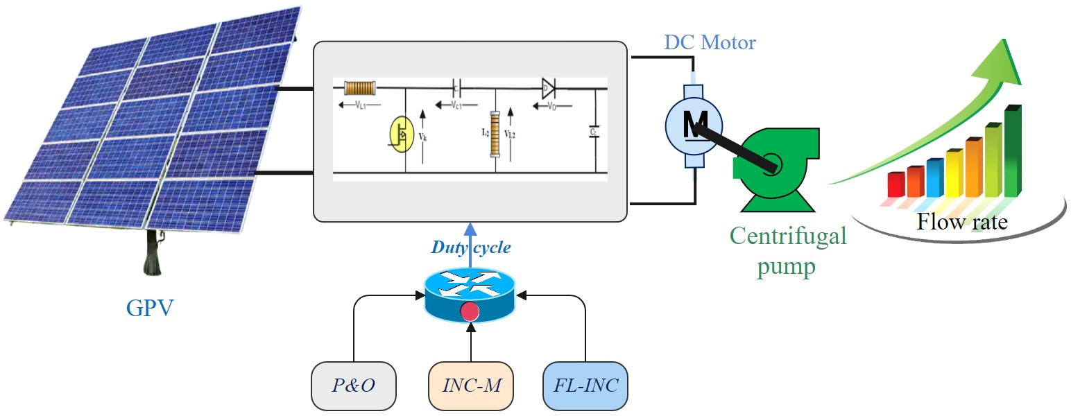
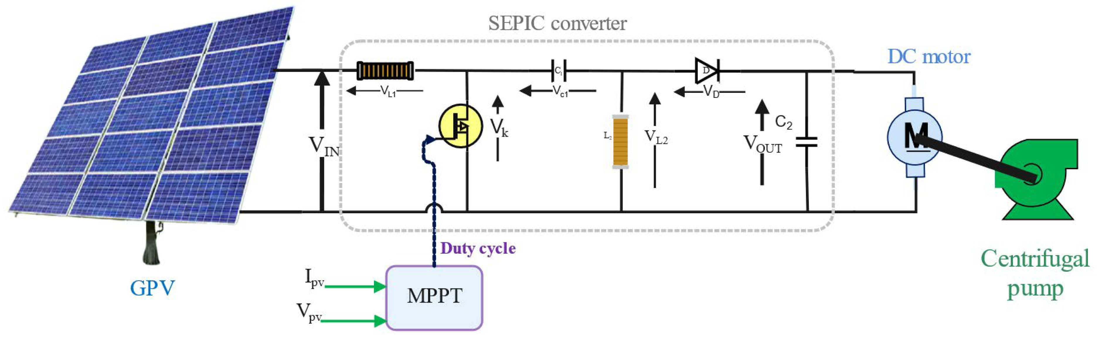
2. Description of the Solar Water Pumping System

Solar pumping system installations typically require the following components: a GPV, a static power converter to improve system efficiency and reliability to optimize the amount of water pumped, and a motor pump assembly. These elements mentioned above are coupled in two ways. As shown in Figure 1a, direct coupling is the basic topology that can be made, in which a motor pump unit is directly connected to the GPV. The main reason for this option is the lack of other electronic devices to control the system, which results in a low-cost solution [23]. However, the direct influence of the coupling on the power delivered by the GPV is reflected by the intersection between the GPV and motor pump characteristics [13]. The main disadvantage of this configuration mode is that it does not allow any regulation of the voltage at the motor terminals, while the transfer of the maximum available power to the GPV is not ensured. In fact, to overcome the latter, an indirect coupling is used, in which a matching stage is inserted between the GPV and the motor pump assembly, as shown in Figure 1b. In fact, this stage acts as an interface between the two equipment and ensures the permanent transfer of maximum power supplied by the generator.

3. Solar Pumping System Constitutions
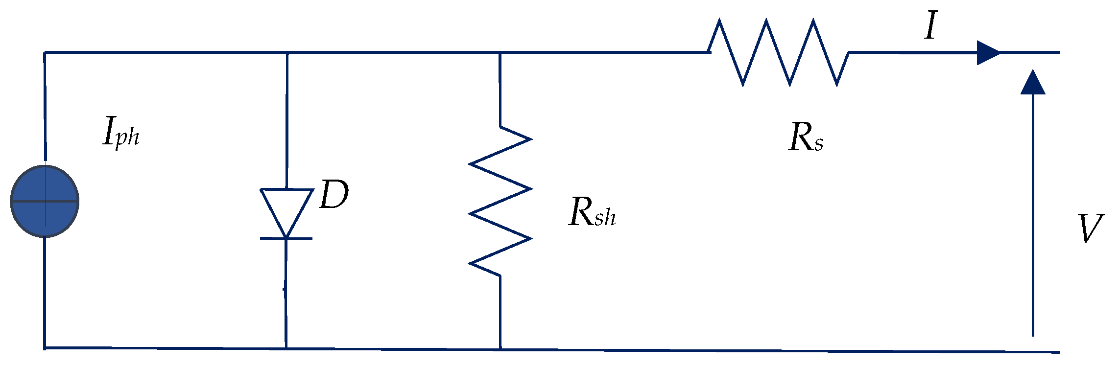
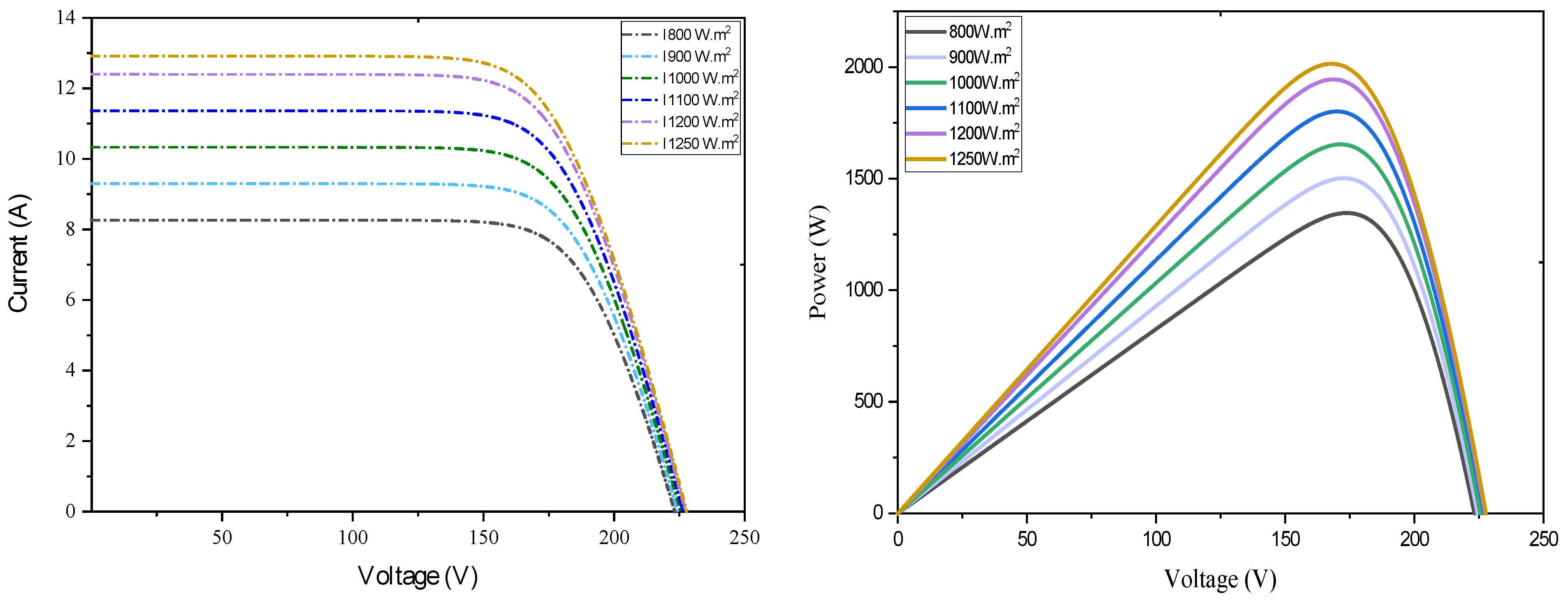
3.1. PV Generator

PV cells are made of a semiconductor material that forms the basic element of a photovoltaic module. A generator typically includes several modules connected in series and in parallel to produce the required current and voltage. Figure 2 shows the most commonly used equivalent schematic of a solar cell, which includes a current source, Iph; a diode; and two parasitic resistors, Rs and Rsh.
The actual current–voltage characteristic can be represented by the following equation:
I = I p h I o b s = I p h I s e x p V + I . R s n V t h 1 V + I . R s R s h
where Iph (A) is the saturation current, Vth (V) is the thermodynamic potential, K (J.K−1) is Boltzmann’s constant, T (K) is the effective cell temperature, e (C) is the electron’s charge, n is the nonideality factor of the junction, I (A) is the current provided by the cell, and V (V) is the voltage across the cell.
Table 1 represents the electrical characteristics of the GPV proposed in this study. Indeed, it is composed of 5 PV panels (REC_330NP), and each panel can generate a peak power of 330 W peak in standard conditions. These panels are connected in series, which allows for generating a voltage of (VMPP) = 173 V and delivering a total peak power of 1650 W peak in standard conditions.
Figure 3 shows the current and power versus voltage evolution for different irradiance patterns and for a cell temperature held constant at 25 °C. From the analysis of power and current, it is interesting to note that the variation of irradiance has a significant effect on these two variables. Indeed, the increase in this characteristic leads to an increase in the power and the current. Table 2 summarizes the progression of the peak power as a function of irradiance.

3.2. Pump Centrifuge

A necessary requirement of the SPS is the motor pump. The latter is made up of two parts: an electric motor coupled to a pump. In this study, the motor used to turn the pump (SQF 0-6-2 DC) is characterized by a nominal current In = 8.4 A, an input voltage ranging from 30 to 300 VDC. In the field of technology, two types of pump technology are generally used in pumping applications: the positive displacement pump and the centrifugal pump [25,26]. The first technology is distinguished by a constant load, whereas centrifugal pumps are distinguished by an aerodynamic characteristic. The latter are characterized by a load of torque that develops with the quadratic form of the drive speed. This characteristic clearly indicates that the drive torque of the pump is almost zero at the start-up. Therefore, the pump can be operated with very low solar irradiation, and as the solar irradiation increases, the drive motor can have a high speed. The proportionality of the different parameters as a function of the speed is expressed by the following equations [27]:
Torque (Cr)—speed (ω):
C r = A . ω 2
Flow (Q)—speed (ω):
Q 2 Q 1 = ω 2 ω 1
Height (H)—speed (ω):
H 2 H 1 = ω 2 ω 1 2

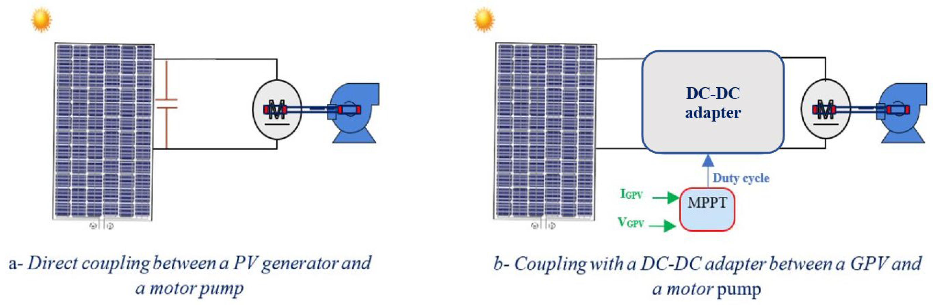
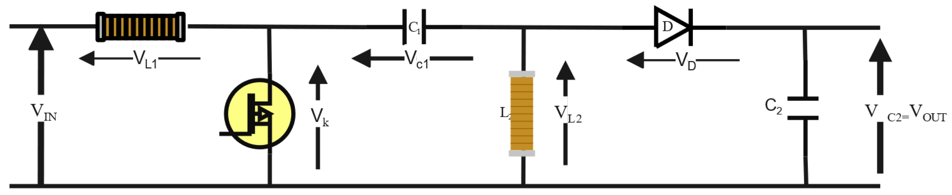
3.3. Matching Stage: SEPIC Converter

The SEPIC is a direct-voltage-to-direct-voltage converter that will allow the output to be greater than, less than, or equal to the input voltage [28]. This is because the voltage of the converter is controlled by the duty cycle. In addition, the SEPIC is analogous to a buck-boost converter with the benefit of having a noninverting output. In effect, it ensures low current ripples. In terms of construction, the SEPIC converter consists of a power switch (IGBT; MOSFET, Thyristor, etc.), a diode, inductors (L1, L2), and capacitors (C1, C2). Figure 4 shows the electrical diagram of this converter. The input inductance L1 of the circuit makes the whole SEPIC converter look like a boost converter. This converter also has the advantage of isolating the input and output by means of the coupling capacitor C1, which protects against a short circuit or an overload at the output. Moreover, the SEPIC has the advantage of being able to cut its output voltage down to zero voltage, unlike a boost converter where the lowest output voltage is equal to the input voltage.
The relation between the load voltage and the converter input voltage is given by [28,29]:
V O U T = 1 α α V I N
where VOUT is the output voltage, VIN is the input voltage, and α is the duty cycle.
Table 3 summarizes the sizing results for the SEPIC converter applied to the studied solar pumping system.

4. Solar Water Pumping System Optimization Techniques

The optimization of the solar pumping system using an MPPT tracker is shown in Figure 5. In addition, the system structure consists of a GPV that powers the electric motor. The latter drives a centrifugal pump through an MPPT controller. Then a series of studies are carried out to give an overview of the influence of MPPT techniques on the performance of the pumping system.

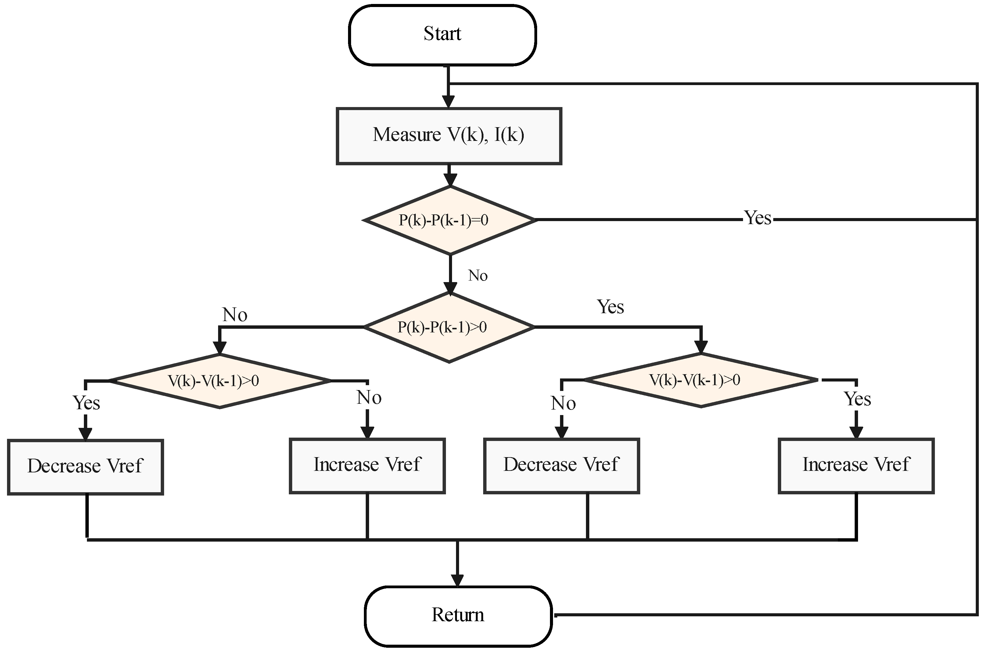
4.1. P&O Optimization Technique

The perturb and observe (P&O) optimization technique is probably the most natural method to find the maximum power point MPP, and its principle is given by the flowchart in Figure 6. Moreover, MPP tracking is independent of temperature and/or irradiance variations. The basic principle of this optimization technique can therefore be extracted from the flowchart in Figure 6:
At a fixed voltage V(k), the corresponding power P(k) delivered by the generator is measured;
After a certain delay, the algorithm imposes a voltage V(k + 1) = V(k) + ΔV and also measures the corresponding power P(k + 1);
If P(k + 1) is greater than P(k), the algorithm seeks to apply for a higher-voltage V(k + 1) = V(k) + ΔV;
Otherwise, the algorithm instead looks to decrease the voltage V(k) = V(k + 1) − ΔV.

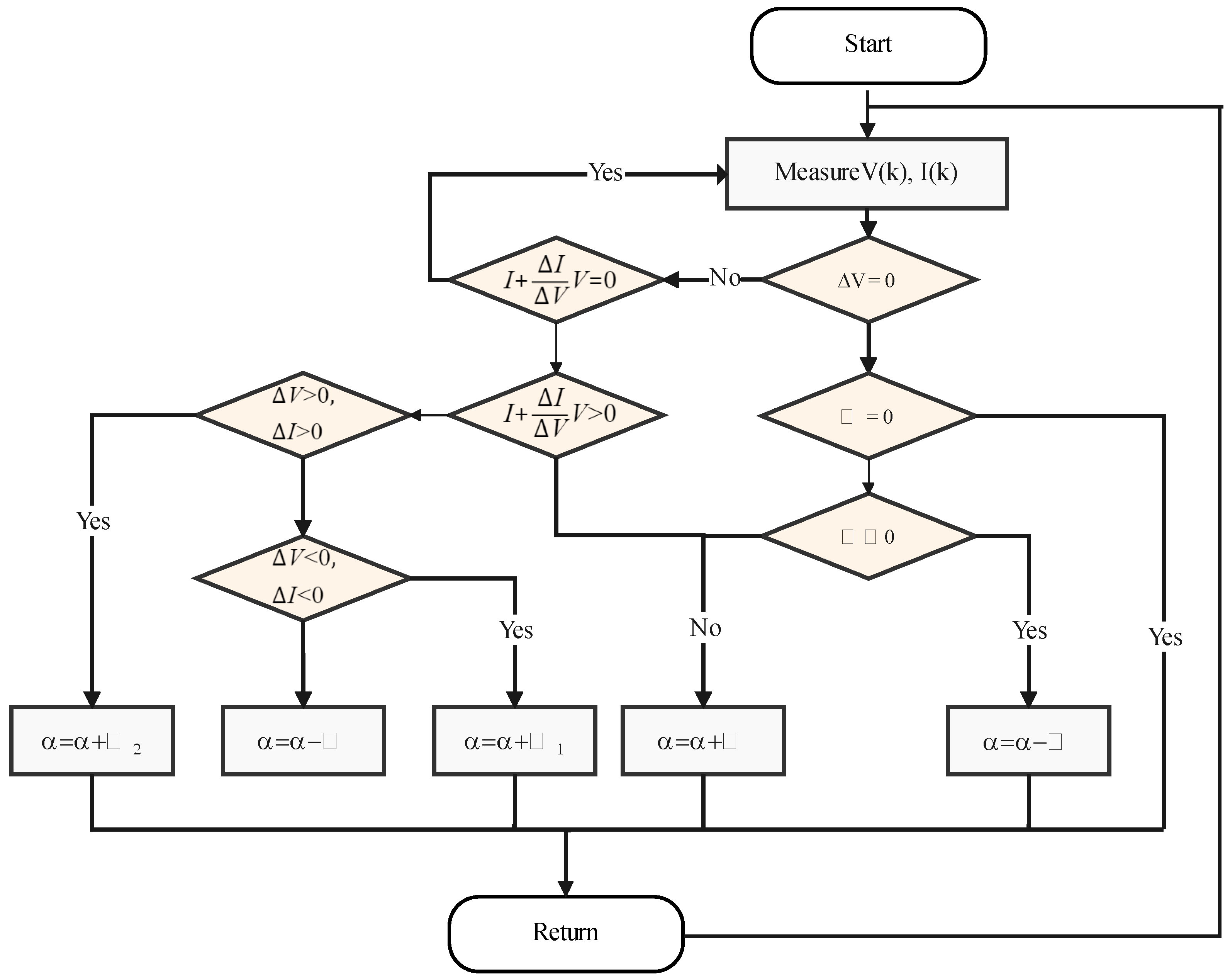
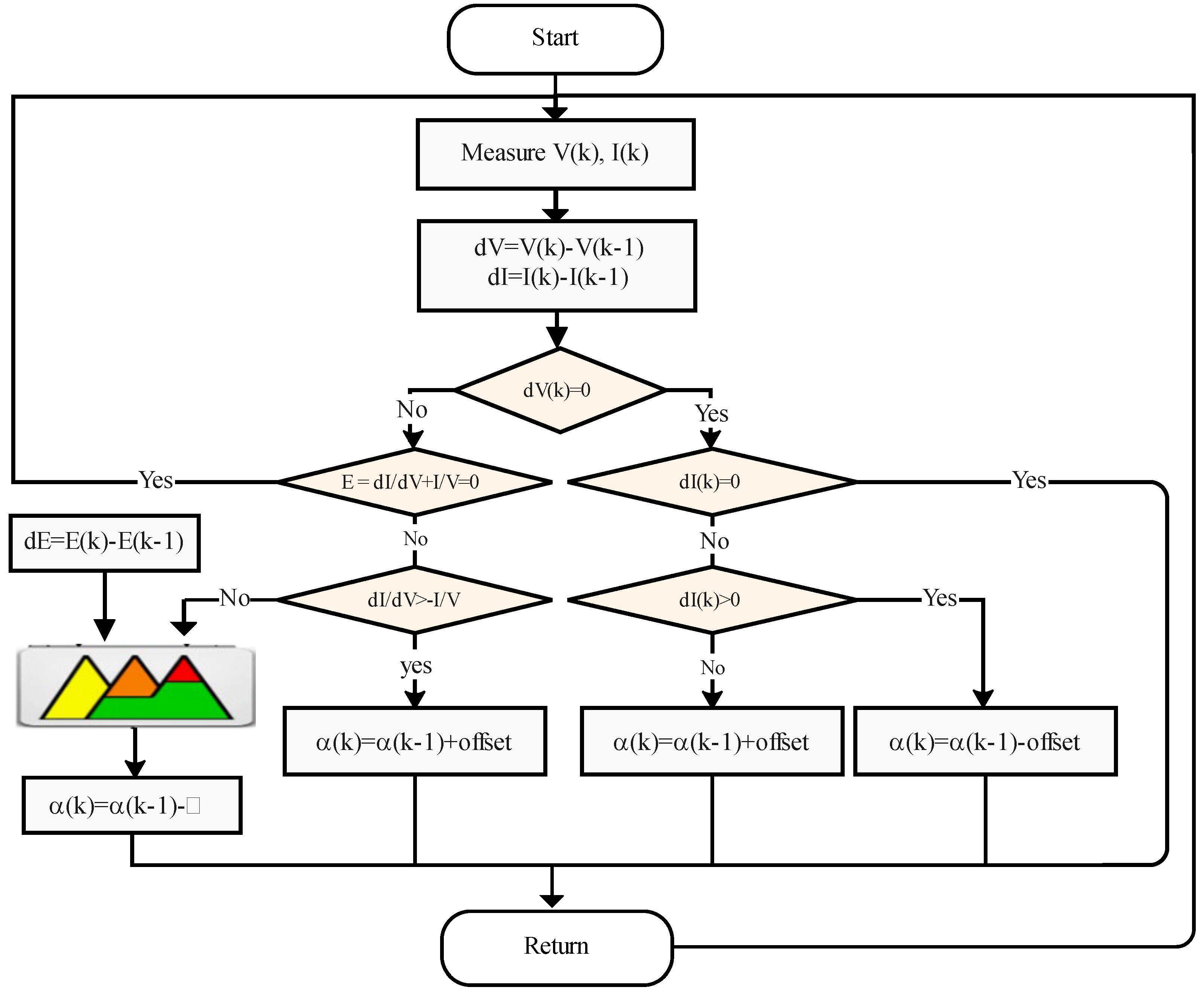
4.2. Incremental Conductance Modified (M-INC) Optimization Technique

Under unstable irradiance and temperature conditions, a variation in voltage leads to a variation in the current. On the other hand, a voltage perturbation leads to a current perturbation when the photovoltaic field is subjected to a sudden change in atmospheric conditions [30]. Contrary to the classical incremental method [31], the M-INC algorithm distinguishes between these operating conditions and, thus, avoids the divergence caused by atmospheric disturbances. Indeed, the modified incremental conductance (M-INC) algorithm is supposed to act in the opposite way of the INC method when the system operates in the partial shading situation. This method is based on the power derivative being zero at MPP. It can be expressed as follows [32]:
d P d V = d I V d V = V d I d V + I = 0
where dP is the power derivative, dV is the voltage derivative, and dI is the current derivative.
Equation (6) can be expressed as follows:
Δ I Δ V = d I d V = I V    
where ΔV and ΔI are the increments of voltage and current. The characteristics of the method can be obtained from the P–V curve and can be written as follows [32]:
d I d V = I V   at   maximum   power   point
I V       d I d V   left   to   maximum   power   point
I V       d I d V   right   to   maximum   power   point
The duty cycle of this technique is calculated by:
α i ( n ) = α i ( n 1 ) ± k i P ( n ) P ( n 1 ) V ( n ) V ( n 1 ) = α i ( n 1 ) ± δ α i
Figure 7 depicts a flowchart of the modified INC algorithm.

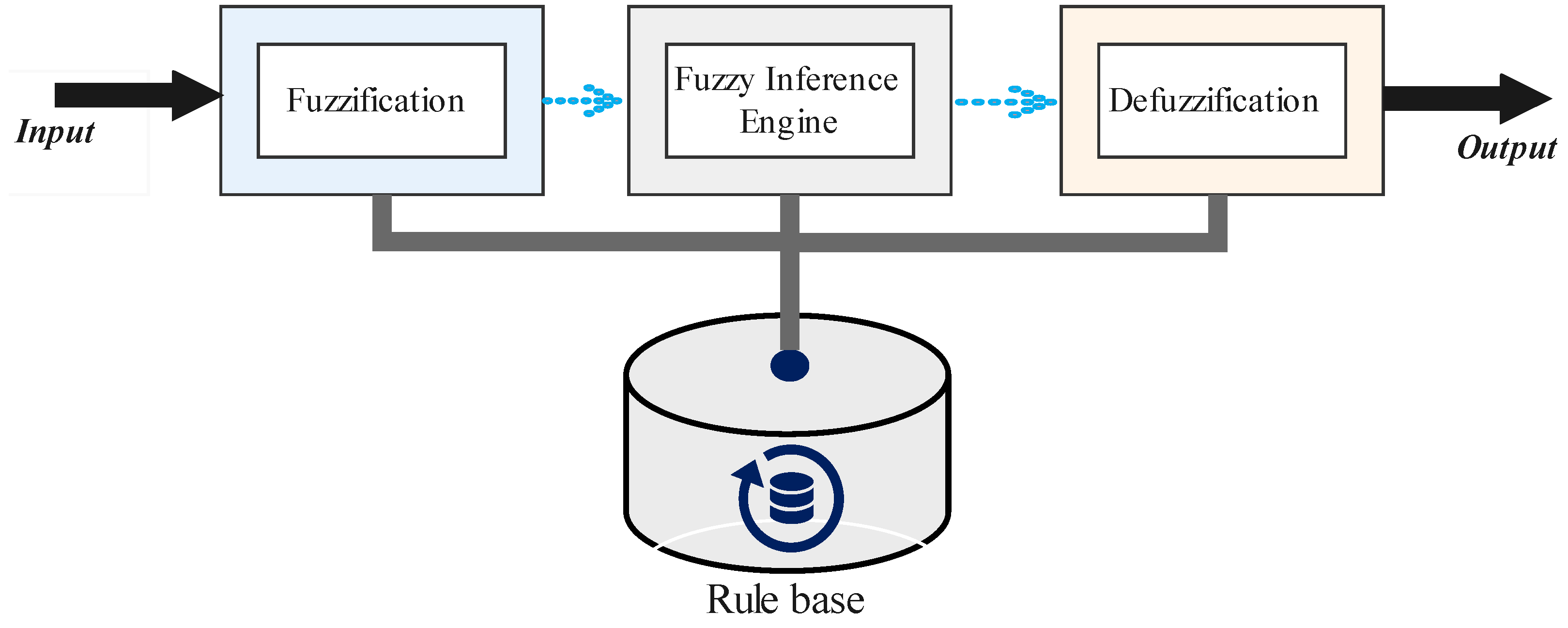
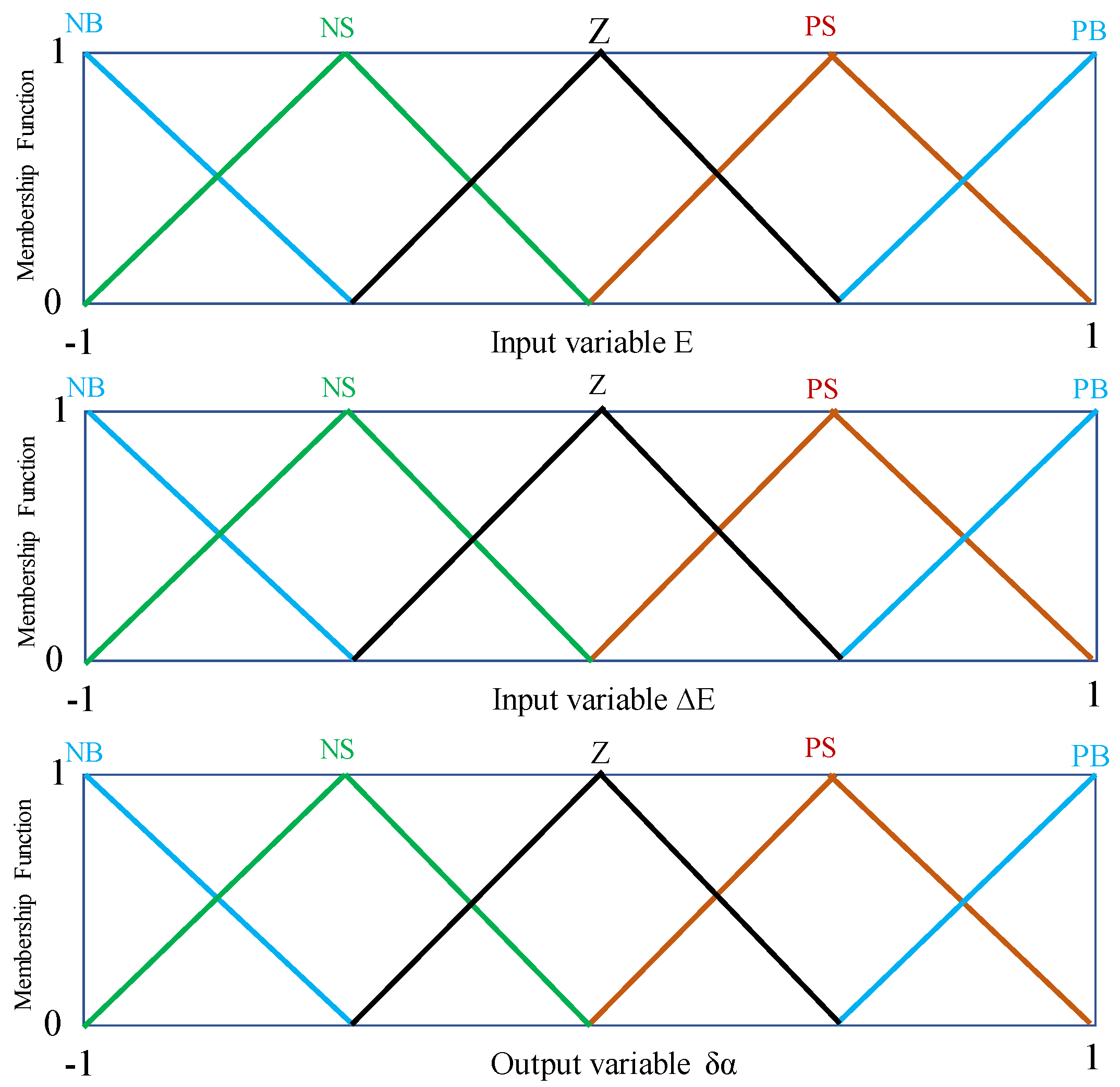
4.3. FL-INC Hybrid Optimization Technique

The fuzzy logic of artificial intelligence is introduced in the incremental conductance technique to develop a new hybrid optimization method named FL-INC. The latter is applied to ensure a better optimization of the SWPS in case of very unstable weather conditions. Fuzzy logic allows the study and representation of imprecise knowledge and approximate reasoning [33]. Figure 8 shows the basic design of a fuzzy logic controller, which is composed of three stages. The first step is the fuzzification step, which consists in converting the input variables (physical variables) into linguistic variables (fuzzy variables), by establishing membership functions for the different input variables. The second step is the inference engine, which includes the inference block and the rule base to determine the output of the fuzzy controller from the inputs resulting from the fuzzification. Finally, defuzzification is the last step of the fuzzy controller; it allows for converting the fuzzy data provided by the inference mechanism into a physical or numerical quantity to define the decision process [34].
The optimization using the fuzzy logic technique can significantly reach the global power point. However, the performance of this control technique depends mainly on the human expertise. Indeed, the rules developed from the human operator’s expertise are expressed in linguistic form. Moreover, these rules determine the dynamic performance of the fuzzy controller [35]. Therefore, applying this reasoning to the incremental algorithm improves the performance of the extracted power. Figure 9 shows a flowchart of the developed hybrid FL-INC technique.
The fuzzy controller proposed in this technique consists of two inputs, E(k) and ∆E(k), which are defined by the following equations:
E k = I k I k 1 V k V k 1 + I K V K
Δ E = E k E k 1
where E(k) is the derivative of the conductance calculated from the measured voltage and current. It is nullified when the operating point attains the MPP. Additionally, ∆E(k) is the error of the input E(k).
Additionally, the output of this fuzzy controller represents the change in the duty cycle (δα). Figure 10 shows the selected membership functions for E, ∆E, and δα.
The triangular membership function is chosen for all fuzzy sets because of its simplicity. The boundaries of the fuzzy variable range are usually normalized between −1 and +1. The control rules are used to make the decision and decide the action at the output of the fuzzy controller, which consists of 25 fuzzy rules, and are grouped in Table 4.
Linguistic variables are expressed as: PB: positive big; PS: positive small; Z: zero; NS: negative small; and NB: negative big.
The control rules can be expressed as follows: rule: if (E is X) and (ΔE is Y), then (δα is W), where: X, Y, and W are the fuzzy sets of input and output variables.
The implementation of the different control rules is based on the instructions below:
If the conductance value is very big, the variation of the duty cycle (δα) must be big so as to quickly bring this conductance to zero;
If the conductance value is close to zero, slight variations in the duty cycle should be applied;
If the conductance value is close to zero and approaches it quickly, the duty cycle must be constant to avoid strong overshoot;
If the conductance reaches zero and the output voltage is not stable, the duty cycle should be varied a little to reduce fluctuations;
If the conductance reaches zero and the output voltage of the converter is stable, the duty cycle should be kept constant;
If the value of the conductance variation is greater than zero, the variation of the duty cycle is negative and vice versa.

5. Simulation Results of the Solar Water Pumping System

5.1. Simulation Conditions

In this section, the MPPT simulation results are obtained through the PSIM simulation software. Indeed, the efficiency of MPPT by optimization techniques is evaluated under irradiation conditions similar to the real conditions. Moreover, a variable irradiance profile (from 200 to 1250 W·m−2) is chosen to test the system performance. This profile includes fast, slow, strong, and stable fluctuations, as shown in Figure 11.
The graph in Figure 11 shows the different levels of irradiance fluctuations as a function of time ti, which are modeled by:
Constant irradiance in the intervals: (0, t1), (t2, t3), (t3, t4), (t4, t5), (t6, t7), and (t8, t9);
Variable irradiance in the intervals: (t1, t2) and (t7, t8);
Abrupt changes in irradiance at times t3 and t4;
This irradiation profile is very unstable in terms of meteorology, which is a good test to evaluate the behavior of the solar pumping system.

5.2. Simulation Results of the Direct Coupling

Figure 12 shows the simulation results of the SWPS in the direct coupled case. It should be noted that the irradiance variation leads to a significant power fluctuation. In addition, the power transmitted to the pump is considerably less than that generated by the GPV, as shown in Table 2. Under standard conditions where the irradiance has a value of 1000 W·m−2, the motor pump receives a power of 961 W, which presents 58% of the peak power (1650 W) produced by the GPV. Moreover, a significant variation of the motor pump voltage is undesirable for the safety of this type of system. Moreover, this configuration has as a problem the dependence between the power supplied by the GPV and the load characteristic. Indeed, the optimization of the energy requires another configuration in which an adaptation unit is introduced downstream of the GPV.

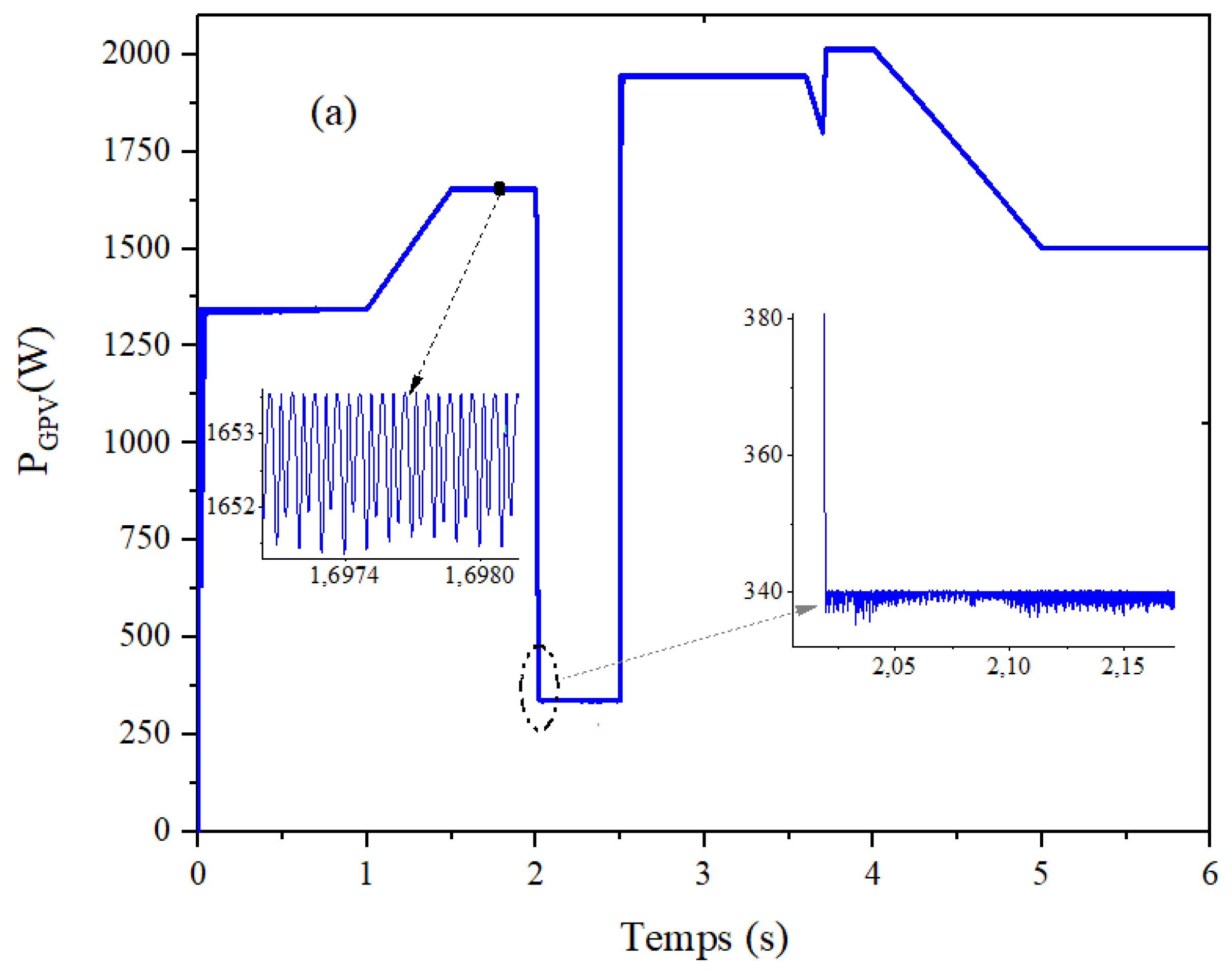
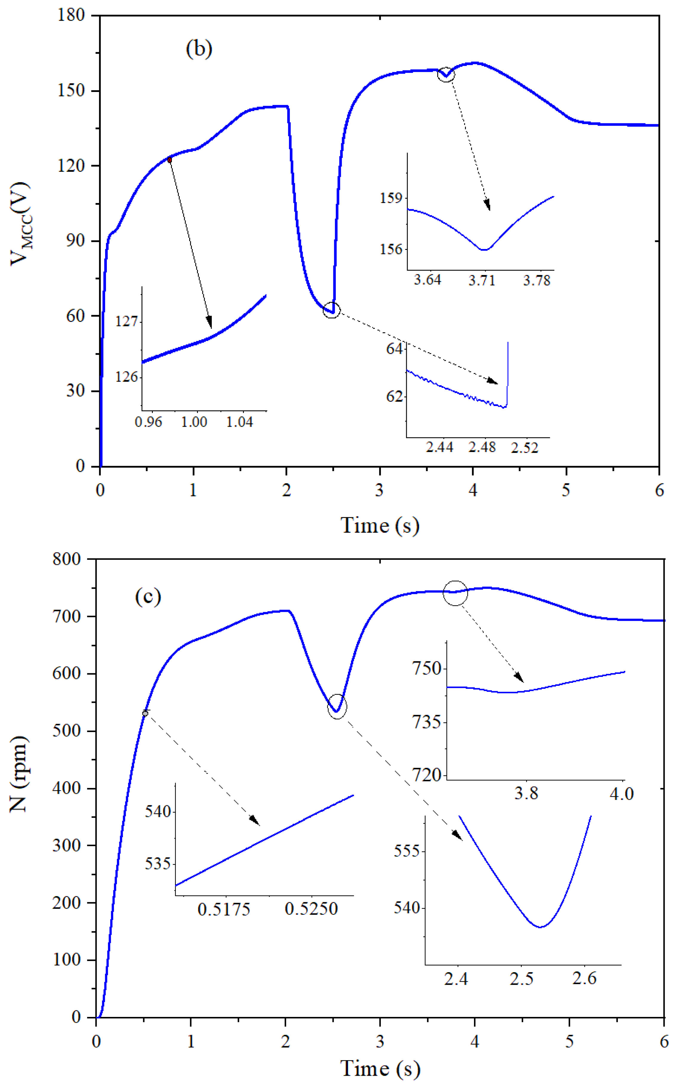
5.3. Simulation Results Using the P&O Optimization Algorithm

Figure 13 shows the evolution of the variables in the indirect coupling between the GPV and the motor pump using the SEPIC converter in the case of optimization by the P&O technique. Figure 13a–c shows, respectively, the variation of the instantaneous electrical power, voltage, and rotational speed of the motor pump as a function of time. Under the standard irradiation conditions applied to the pumping system, the extracted power remains much higher and presents an increase of 47% compared with the direct coupling. In this regard, it is important to note that a clear improvement of the system from the power point of view with the developed controller is observed. Indeed, the power is perfectly improved compared with the direct coupling. However, this technique presents oscillations of about ±2 W, while with the decrease in the duty cycle, it is possible to decrease these oscillations, but the tracking will be much slower. To test the behavior of the MPPT–P&O technique under a fast variation of the irradiance, the instant t3 presents an instantaneous drop of this one. Under these climatic conditions, the extracted power undergoes a decrease proportional to the irradiance. Compared with the direct coupling, the extracted power remains much higher. Finally, the P&O technique allows a good optimization of the pumping system. However, the decrease in the increment step of the duty cycle leads to a decrease in the power fluctuation, while the tracking speed does not adapt quickly to the irradiance changes. From Figure 13b, compared with direct coupling, the terminal voltage of the pump motor is significantly improved, especially during abrupt changes in irradiance (t3, t4, and t5). Moreover, under steady-state conditions, the voltage has fluctuations of the order of 0.05 V, which is quite acceptable for pump systems. From Figure 13c, the speed of the motor pump is significantly improved and is almost generated for the entire range of weather variations. Compared with the direct coupling, this speed is significantly increased. In fact, it shows a significant improvement in that it has become 667 rpm instead of 310 rpm, a gain of 46%.

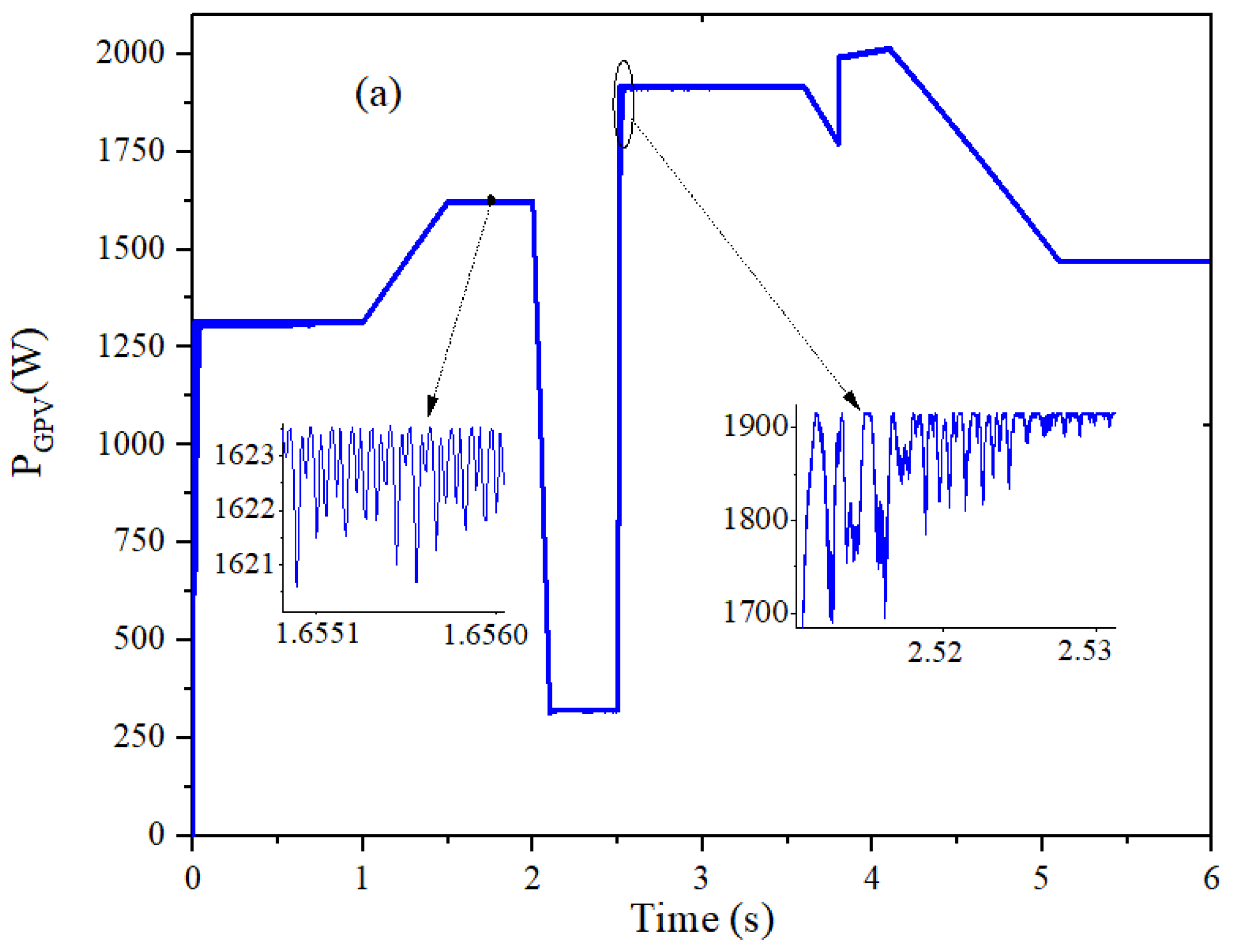
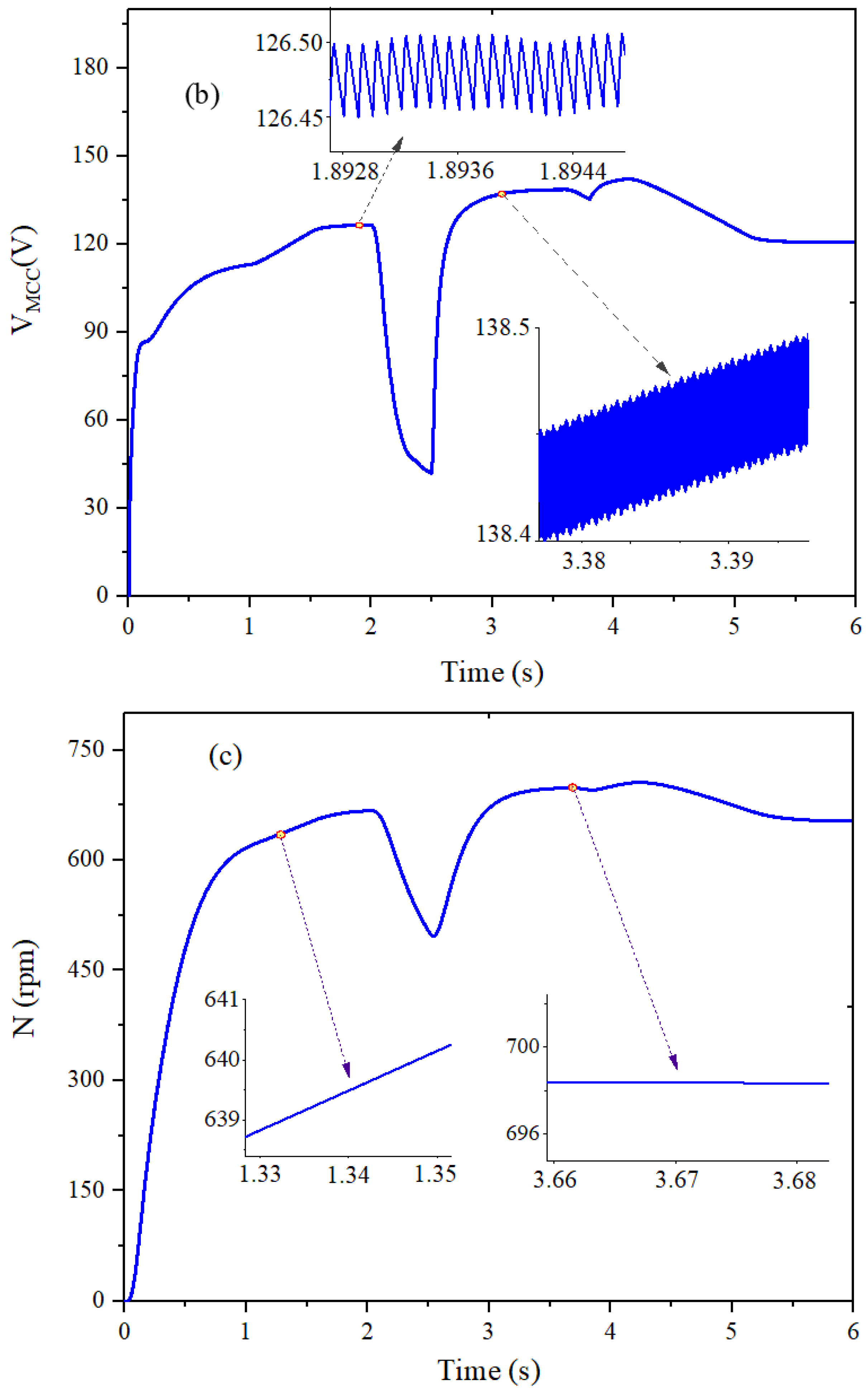
5.4. Simulation Results Using the M-INC Optimization Algorithm

Figure 14 shows the simulation results of the indirect coupling between the GPV and the motor pump using the SEPIC converter endowed with the M-INC technique. Figure 14a–c shows, respectively, the variation of the instantaneous electrical power, voltage, and rotational speed of the motor pump as a function of time. From Figure 14, it is important to note that the tracking speed is significantly higher than that obtained by the P&O technique. Indeed, under standard conditions, a value of 1654 W is noted, which is a gain of almost 3% compared with the P&O technique. In addition, the behavior of the M-INC control is quite satisfactory. Indeed, the tracking speed is significantly improved due to the fact that the system adapts quickly to changes. However, in the case of sudden changes in irradiance (t3), the system suffers from overshoot, which affects the quality of the energy transmitted to the motor pump. The speed of the motor pump with this technique is significantly improved compared with the P&O technique, as shown in Figure 14c. The same behavior is observed for the voltage characteristic curve. Finally, the results obtained highlight the drawbacks of coupling by the M-INC technique for an application where the irradiance variation is very unstable. The power is significantly improved and does not deviate much from the MPP under unstable weather conditions, except that it suffers from power overshoot, which will affect the power quality.

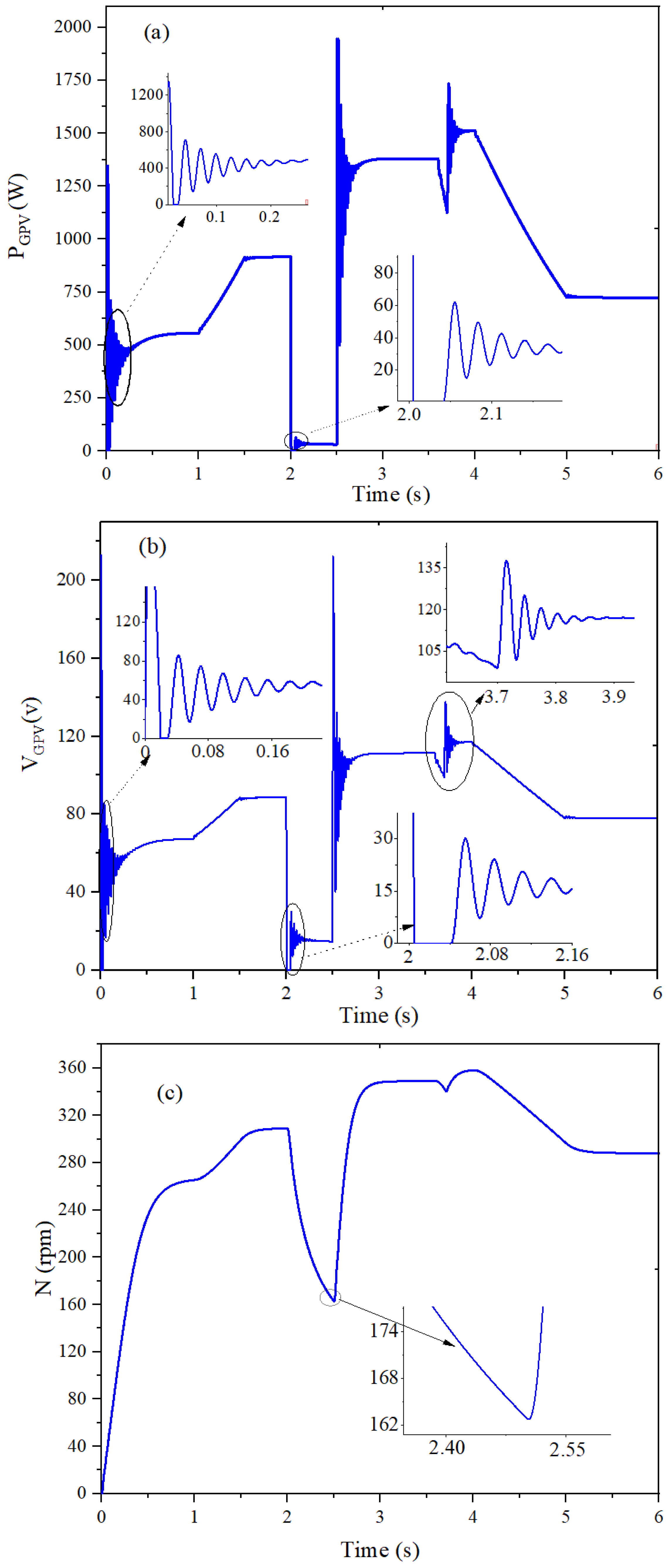
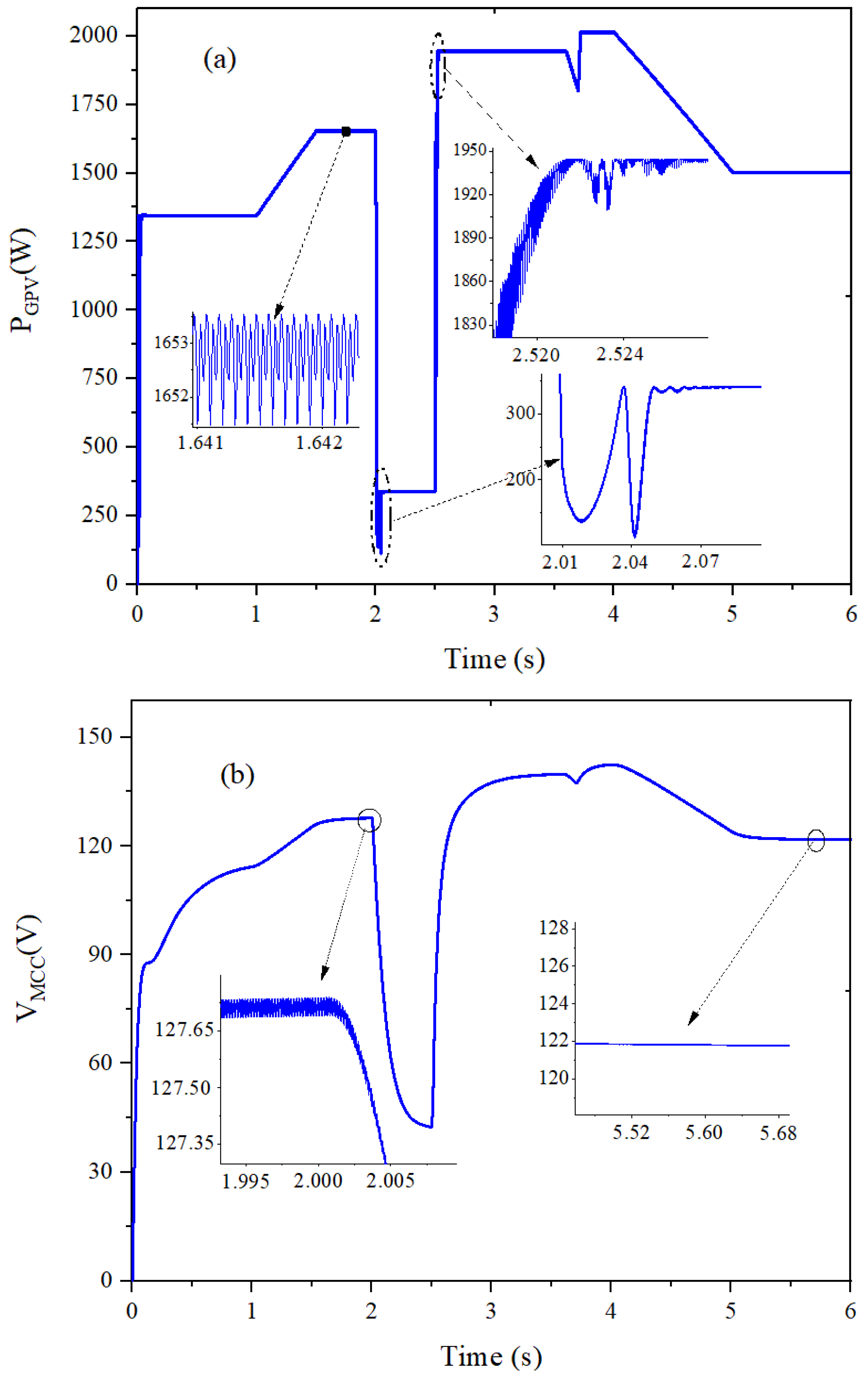
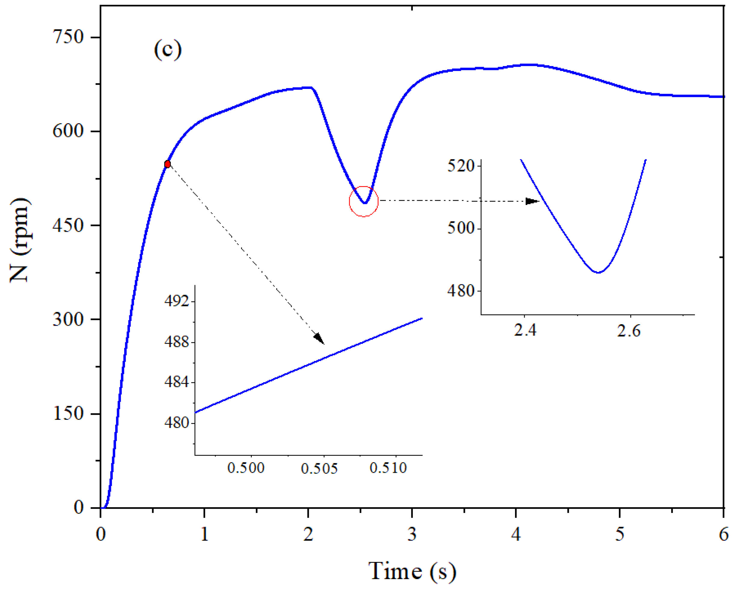
5.5. Simulation Results Using the FL-INC Optimization Algorithm

Simulation results of the hybrid FL-INC technique of indirect coupling by a SEPIC converter with this algorithm are shown in Figure 15. It is interesting to note that this technique has a significant effect on overshoot, which is greatly attenuated compared with the M-INC technique. In addition, this technique improves the quality of the power transmitted to the SWPS while ensuring the required performance for such a system. Finally, the extracted power has a more improved character compared with the other techniques, as the tracking rate quickly reaches the maximum power point under different weather conditions. In addition, this power reflects the available solar energy potential while contributing to the preservation of the environment and the reduction of greenhouse gas emissions and climate change mitigation. This is due to the fact that this power presents a sufficient amount of solar water pumping applications.

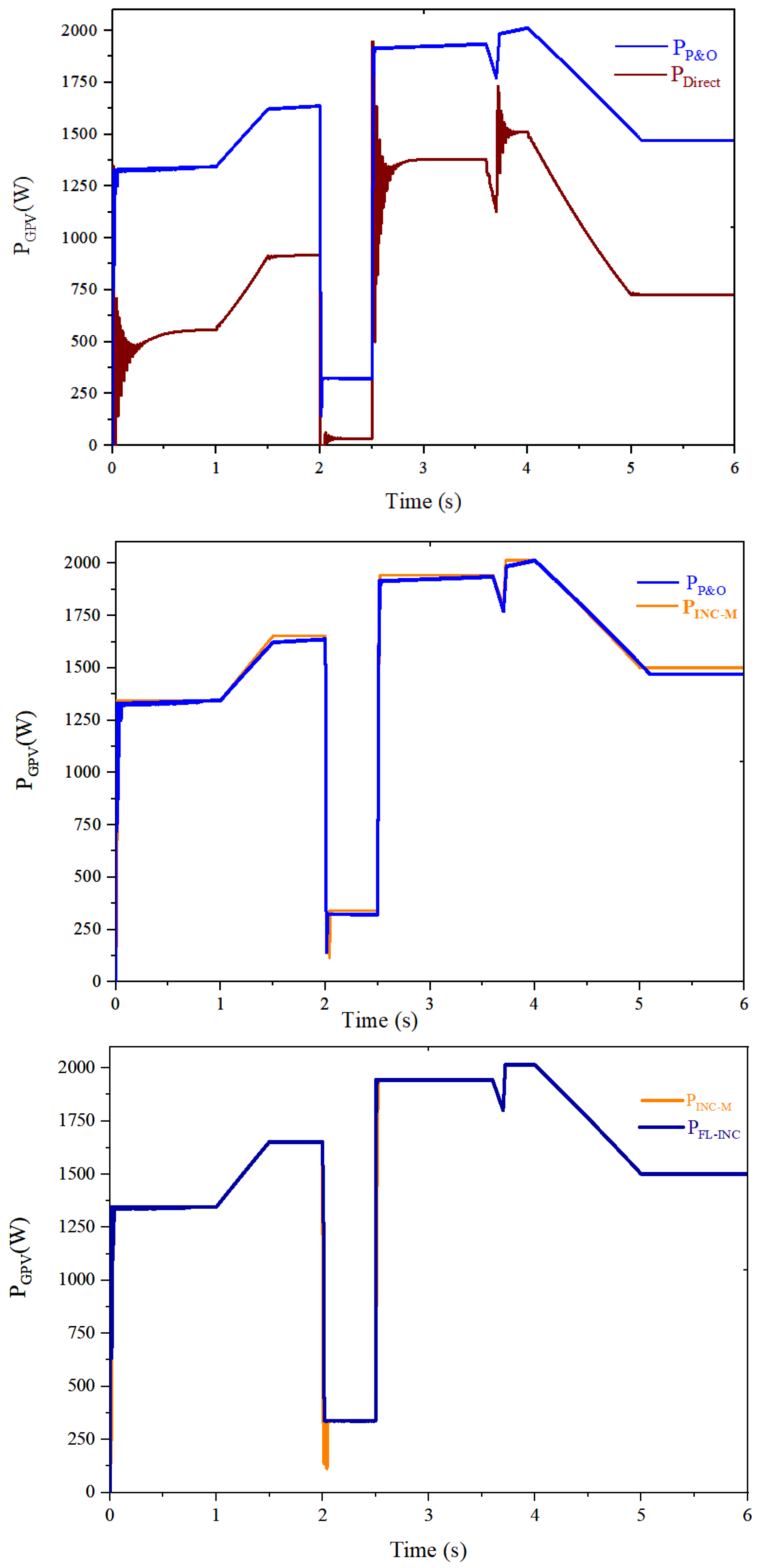
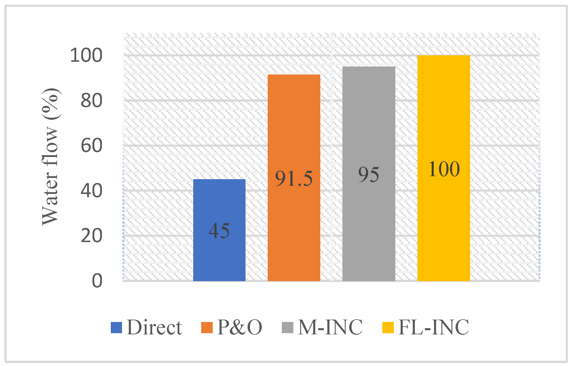
6. Comparative Study between the Studied Optimization Techniques

Figure 16 shows the simulation results of the instantaneous power extracted from the GPV across the four types of coupling, that is, direct coupling and coupling by an MPPT tracker. The latter is controlled by three types of algorithms: P&O, modified incremental, and hybrid FL-INC. The efficiency of the SWPS is very influenced by the weather conditions and the operating point of the system. The results in Figure 16 show that with direct coupling, the system efficiency is poor and the system operates farther from the maximum power point. The SEPIC converter with MPPT control has variable efficiency and tracking dynamics. With the P&O technique, the tracking of the power point is significantly improved over direct coupling, but the system is not able to have a better tracking speed during sudden changes in irradiance. The M-INC technique can overcome the tracking problem, but suffers from power overshoot during sudden irradiance changes compared with the hybrid technique.
To show the influence of the power point tracking techniques on the solar water pumping flow rate, the histogram in Figure 17 presents a comparative study of the flow rate for each technique used. In fact, the flow rate in this simulation is calculated from a rotational speed that varies over the entire range of the simulation. According to Equation (3), the calculated flow rate is directly in proportion to the speed motor in the simulation. From the results, the hybrid technique has a better pumping rate than the others, that is, 55% rate compared with direct coupling, 8.5% compared with the P&O technique, and 5% rate compared with M-INC. Finally, the hybrid technique based on fuzzy logic for the artificial intelligence and the incremental technique has effectively improved the performance of SWPS.

7. Conclusions

In this paper, the behavior and functioning of a solar water pumping system are studied. In a direct coupling, the performance of the system is related to the operating point. The latter can be more or less distant from the MPP as a function of climatic conditions. In this case, the efficiency of the MPPT depends strongly on the meteorological data and the characteristics of the motor pump. In this perspective, the improvement of the efficiency and power transfer quality of the system is provided by the SEPIC converter proposed in this study. Then, different control techniques of the SEPIC converter have been developed to optimize the power transfer. Finally, the analysis of the simulation results reveals that the combined hybrid method of fuzzy logic and the INC technique provides excellent static and dynamic performance compared with other techniques in terms of robustness, efficiency, stability, and tracking speed. According to the simulation results, the hybrid FL-INC technique provides a pumping rate gain of 5% over the M-INC technique, 8.5% over the P&O technique, and 55% over the direct coupling. The perspectives of this research work would be to test the developed optimization techniques in a real operating context.

Author Contributions

Conceptualization, A.H., M.A.M. and N.E.O.; methodology, M.A.M., S.M. and A.H.; software, A.H., S.M. and M.A.M.; validation, A.H., M.A.M., A.S.A.-S. and N.E.O.; formal analysis, A.H., M.A.M., S.M. and N.E.O.; investigation, S.M., M.A.M., N.E.O. and A.S.A.-S.; resources, S.M., M.A.M., N.E.O. and A.H.; data curation, A.H., S.M. and N.E.O.; writing—original draft preparation, A.H., N.E.O. and M.A.M.; writing—review and editing, A.H., S.M., M.A.M. and A.S.A.-S.; visualization, A.H., M.A.M. and S.M.; supervision, M.A.M. and A.S.A.-S.; project administration, M.A.M. and A.S.A.-S.; funding acquisition, A.S.A.-S. and M.A.M. All authors have read and agreed to the published version of the manuscript.

Funding

This research is supported by Khalifa University as part of research excellence award 8474000427 and ASPIRE under the ASPIRE Virtual Research Institute (VRI) Program, Award Number VRI20-07.

Data Availability Statement

The data are available upon request from the corresponding author (M.A.M.).

Conflicts of Interest

The authors declare no conflict of interest.

Abbreviations

SWPSsolar water pumping system
FL-INCfuzzy logic and incremental conductance
SEPICsingle-ended primary inductance converter
INCincremental conductance
M-INCmodified incremental conductance
P&Operturb and observe
HChill climbing
ABCartificial bee colony
PVphotovoltaic
IGBTinsulated gate bipolar transistor
MOSFETmetal oxide semiconductor field effect transistor
GPVgenerator photovoltaic
MPPmaximum power point
MPPTmaximum power point tracking

References

  1. Al-Sumaiti, A.S.; Ahmed, M.H.; Salama, M. Residential Load Management Under Stochastic Weather Condition in Developing Countries. Electr. Power Compon. Syst. 2014, 42, 1452–1473. [Google Scholar] [CrossRef]
  2. Mossa, M.A.; Gam, O.; Bianchi, N.; Quynh, N.V. Enhanced Control and Power Management for a Renewable Energy-Based Water Pumping System. IEEE Access 2022, 10, 36028–36056. [Google Scholar] [CrossRef]
  3. Mossa, M.A.; Gam, O.; Bianchi, N. Dynamic Performance Enhancement of a Renewable Energy System for Grid Connection and Stand-Alone Operation with Battery Storage. Energies 2022, 15, 1002. [Google Scholar] [CrossRef]
  4. Mossa, M.A.; Echeikh, H.; Quynh, N.V.; Bianchi, N. Performance dynamics improvement of a hybrid wind/fuel cell/battery system for standalone operation. IET Renew. Power Gener. 2022, 1–27. [Google Scholar] [CrossRef]
  5. Banhidarah, A.K.; Al-Sumaiti, A.S. Heuristic search algorithms for optimal locations and sizing of distributed generators in the grid: A brief recent review. In Proceedings of the 2018 Advances in Science and Engineering Technology International Conferences (ASET), Dubai, Sharjah, Abu Dhabi, United Arab Emirates, 6 February–5 April 2018; pp. 1–5. [Google Scholar] [CrossRef]
  6. Sharma, G.D.; Shah, M.I.; Shahzad, U.; Jain, M.; Chopra, R. Exploring the nexus between agriculture and greenhouse gas emissions in BIMSTEC region: The role of renewable energy and human capital as moderators. J. Environ. Manag. 2021, 297, 113316. [Google Scholar] [CrossRef]
  7. Mossa, M.A.; Echeikh, H.; Iqbal, A. Enhanced control technique for a sensor-less wind driven doubly fed induction generator for energy conversion purpose. Energy Rep. 2021, 7, 5815–5833. [Google Scholar] [CrossRef]
  8. Liu, X.; Liu, Z. Exploring the impact of media discourse on social perceptions towards biomass energy utilization in China. Energy Strategy Rev. 2022, 42, 100896. [Google Scholar] [CrossRef]
  9. Li, J.; Yang, Z.; Yu, Z.; Shen, J.; Duan, Y. Influences of climatic environment on the geothermal power generation potential. Energy Convers. Manag. 2022, 268, 115980. [Google Scholar] [CrossRef]
  10. Fujiwara, R.; Fukuhara, R.; Ebiko, T.; Miyatake, M. Forecasting design values of tidal/ocean power generator in the strait with unidirectional flow by deep learning. Intell. Syst. Appl. 2022, 14, 200067. [Google Scholar] [CrossRef]
  11. World Health Organization. Progress on Sanitation and Drinking Water: 2015 Update and MDG Assessment; World Health Organization: Geneva, Switzerland, 2015. [Google Scholar]
  12. Al-Sumaiti, A.S.; Kavousi-Fard, A.; Salama, M.; Pourbehzadi, M.; Reddy, S.; Rasheed, M.B. Economic Assessment of Distributed Generation Technologies: A Feasibility Study and Comparison with the Literature. Energies 2020, 13, 2764. [Google Scholar] [CrossRef]
  13. Diab, A.A.Z.; Sultan, H.M.; Do, T.D.; Kamel, O.M.; Mossa, M.A. Coyote Optimization Algorithm for Parameters Estimation of Various Models of Solar Cells and PV Modules. IEEE Access 2020, 8, 111102–111140. [Google Scholar] [CrossRef]
  14. Belhaouas, N.; Mehareb, F.; Assem, H.; Kouadri-Boudjelthia, E.; Bensalem, S.; Hadjrioua, F.; Aissaoui, A.; Bakria, K. A new approach of PV system structure to enhance performance of PV generator under partial shading effect. J. Clean. Prod. 2021, 317, 128349. [Google Scholar] [CrossRef]
  15. Hilali, A.; Mardoude, Y.; Mahfoud, M.E.; Essahlaoui, A.; Houssam, M.; Rahali, A. Photovoltaic Water Pumping System: Modeling and Simulation of Characteristics for Direct Coupling. In Digital Technologies and Applications; Springer: Cham, Switzerland, 2022; pp. 651–660. [Google Scholar] [CrossRef]
  16. Spier, D.W.; Oggier, G.G.; da Silva, S.A.O. Dynamic modeling and analysis of the bidirectional DC-DC boost-buck converter for renewable energy applications. Sustain. Energy Technol. Assess. 2019, 34, 133–145. [Google Scholar] [CrossRef]
  17. Sakthivel, K.; Krishnasamy, R.; Balasubramanian, K.; Krishnakumar, V.; Ganesan, M. Averaged state space modeling and the applicability of the series Compensated Buck-Boost converter for harvesting solar Photo Voltaic energy. Sustain. Energy Technol. Assess. 2022, 53, 102611. [Google Scholar] [CrossRef]
  18. Hilali, A.; Mardoude, Y.; Akka, Y.B.; Alami, H.E.; Rahali, A. Design, modeling and simulation of perturb and observe maximum power point tracking for a photovoltaic water pumping system. Int. J. Electr. Comput. Eng. IJECE 2022, 12, 4. [Google Scholar] [CrossRef]
  19. Jately, V.; Azzopardi, B.; Joshi, J.; Venkateswaran, V.B.; Sharma, A.; Arora, S. Experimental Analysis of hill-climbing MPPT algorithms under low irradiance levels. Renew. Sustain. Energy Rev. 2021, 150, 111467. [Google Scholar] [CrossRef]
  20. Kumar, R.; Khandelwal, S.; Upadhyay, P.; Pulipaka, S. Global maximum power point tracking using variable sampling time and p-v curve region shifting technique along with incremental conductance for partially shaded photovoltaic systems. Sol. Energy 2019, 189, 151–178. [Google Scholar] [CrossRef]
  21. Pilakkat, D.; Kanthalakshmi, S. Single phase PV system operating under Partially Shaded Conditions with ABC-PO as MPPT algorithm for grid connected applications. Energy Rep. 2020, 6, 1910–1921. [Google Scholar] [CrossRef]
  22. Hilali, A.; Mardoude, Y.; Essahlaoui, A.; Rahali, A.; Ouanjli, N.E. Migration to solar water pump system: Environmental and economic benefits and their optimization using genetic algorithm Based MPPT. Energy Rep. 2022, 8, 10144–10153. [Google Scholar] [CrossRef]
  23. Diab, A.A.Z.; Mohamed, M.A.; Al-Sumaiti, A.; Sultan, H.; Mossa, M. A Novel Hybrid Optimization Algorithm for Maximum Power Point Tracking of Partially Shaded Photovoltaic Systems. In Advanced Technologies for Solar Photovoltaics Energy Systems; Motahhir, S., Eltamaly, A.M., Eds.; Springer International Publishing: Berlin/Heidelberg, Germany, 2021; pp. 201–230. [Google Scholar] [CrossRef]
  24. Eltamaly, A.M. Musical chairs algorithm for parameters estimation of PV cells. Sol. Energy 2022, 241, 601–620. [Google Scholar] [CrossRef]
  25. Wang, C.; Shi, W.; Wang, X.; Jiang, X.; Yang, Y.; Li, W.; Zhou, L. Optimal design of multistage centrifugal pump based on the combined energy loss model and computational fluid dynamics. Appl. Energy 2017, 187, 10–26. [Google Scholar] [CrossRef]
  26. Fatigati, F.; di Battista, D.; Cipollone, R. Design improvement of volumetric pump for engine cooling in the transportation sector. Energy 2021, 231, 120936. [Google Scholar] [CrossRef]
  27. Yao, F.; Sun, H. The stability criterion of pumps. In Proceedings of the 2011 International Conference on Electronic Mechanical Engineering and Information Technology, Harbin, China, 12–14 August 2011; pp. 342–344. [Google Scholar] [CrossRef]
  28. Rais, Y.; Aroudi, A.E.; Zakriti, A.; Khamlichi, A. Modeling and design of voltage-mode controlled PV-fed SEPIC converter. IFAC-Pap. 2022, 55, 514–519. [Google Scholar] [CrossRef]
  29. Chellakhi, A.; el Beid, S.; Abouelmahjou, Y. An improved adaptable step-size P&O MPPT approach for standalone photovoltaic systems with battery station. Simul. Model. Pract. Theory 2022, 121, 102655. [Google Scholar] [CrossRef]
  30. Mossa, M.A.; Gam, O.; Bianchi, N. Performance Enhancement of a Hybrid Renewable Energy System Accompanied with Energy Storage Unit Using Effective Control System. Int. J. Robot. Control Syst. 2022, 2, 140–171. [Google Scholar] [CrossRef]
  31. Tey, K.S.; Mekhilef, S. Modified incremental conductance MPPT algorithm to mitigate inaccurate responses under fast-changing solar irradiation level. Sol. Energy 2014, 101, 333–342. [Google Scholar] [CrossRef]
  32. Motahhir, S.; Chalh, A.; el Ghzizal, A.; Derouich, A. Development of a low-cost PV system using an improved INC algorithm and a PV panel Proteus model. J. Clean. Prod. 2018, 204, 355–365. [Google Scholar] [CrossRef]
  33. Ganjeh-Alamdari, M.; Alikhani, R.; Perfilieva, I. Fuzzy logic approach in salt and pepper noise. Comput. Electr. Eng. 2022, 102, 108264. [Google Scholar] [CrossRef]
  34. Reyes-García, C.A.; Torres-García, A.A. Chapter 8—Fuzzy logic and fuzzy systems. In Biosignal Processing and Classification Using Computational Learning and Intelligence; Torres-García, A.A., Reyes-García, C.A., Villaseñor-Pineda, L., Mendoza-Montoya, O., Eds.; Academic Press: Cambridge, MA, USA, 2022; pp. 153–176. [Google Scholar] [CrossRef]
  35. Bose, B.K. Chapter 11—Fuzzy logic and applications. In Power Electronics and Motor Drives, 2nd ed.; Bose, B.K., Ed.; Academic Press: Cambridge, MA, USA, 2021; pp. 789–874. [Google Scholar] [CrossRef]
Figure 1. Coupling types between the motor pump and the GPV.
Energies 15 08518 g001
Figure 2. Electrical model of a photovoltaic cell [24].
Energies 15 08518 g002
Figure 3. Current-Voltage and Power-Voltage characteristics of GPV under variable irradiance.
Energies 15 08518 g003
Figure 4. Electrical diagram of a SEPIC converter [28].
Energies 15 08518 g004
Figure 5. Solar water pumping system optimization structure.
Energies 15 08518 g005
Figure 6. Flowchart of the P&O algorithm [27].
Energies 15 08518 g006
Figure 7. Flowchart of the M-INC algorithm.
Energies 15 08518 g007
Figure 8. Fuzzy logic controller structure.
Energies 15 08518 g008
Figure 9. Flowchart of the hybrid technique FL-INC.
Energies 15 08518 g009
Figure 10. Membership functions of the input (E, ∆E) and output (δα) variables.
Energies 15 08518 g010
Figure 11. Irradiance profile used for simulation.
Energies 15 08518 g011
Figure 12. Simulation results for direct coupling. (a) Instantaneous power extracted from the GPV, (b) terminal voltage at the pump motor, (c) rotation speed of the pump motor.
Energies 15 08518 g012
Figure 13. Simulation results associated with the P&O technique. (a) Instantaneous power extracted from the GPV, (b) terminal voltage at the pump motor, (c) rotation speed of the pump motor.
Energies 15 08518 g013aEnergies 15 08518 g013b
Figure 14. Simulation results associated with the M-INC technique. (a) Instantaneous power extracted from the GPV, (b) terminal voltage at the pump motor, (c) rotation speed of the pump motor.
Energies 15 08518 g014aEnergies 15 08518 g014b
Figure 15. Simulation results associated with the FL-INC technique. (a) Instantaneous power extracted from the GPV, (b) terminal voltage at the pump motor, (c) rotation speed of the pump motor.
Energies 15 08518 g015aEnergies 15 08518 g015b
Figure 16. Instantaneous power of different solar water pumping techniques studied.
Energies 15 08518 g016
Figure 17. Water flow pumped from different techniques.
Energies 15 08518 g017
Table 1. GPV under investigation specifications.
Voc (V)Isc (A)Pmpp (W)Rsh (kΩ)Rs (mΩ)Vmpp (V)Impp (A)
4110.333017334.69.55
Table 2. Peak power evolution as a function of irradiance.
Irradiance (W·m−2)GPV Temperature (°C)Peak Power (W·m−2)
800251347
900251508
1000251657
1100251803
1200251950
1250252018
Table 3. SEPIC converter features.
ComponentDesignateValue
Coupling capacitorC1250 µF
InductorL1 = L21.5 mH
Filtering capacitorC2500 µF
Hashing frequencyf10 kHz
Table 4. Base of the fuzzy controller rules used for FL-INC.
ΔENBNSZPSPB
E
NBZZPBPBPB
NSZZPSPSPS
ZPSZZZNS
PSNSNSNSZZ
PBNBNBNBZZ
Publisher’s Note: MDPI stays neutral with regard to jurisdictional claims in published maps and institutional affiliations.

