Article

Effect of Mixing Section Acoustics on Combustion Instability in a Swirl-Stabilized Combustor

School of Mechanical Engineering, Chungbuk National University, Cheongju 28644, Korea
*
Author to whom correspondence should be addressed.
Energies 2022, 15(22), 8492; https://doi.org/10.3390/en15228492
Submission received: 23 September 2022 / Revised: 2 November 2022 / Accepted: 11 November 2022 / Published: 14 November 2022
(This article belongs to the Special Issue Low-Emission Combustion Techniques: Latest Advances and Prospects)

Abstract

:
An experimental study was performed to investigate the characteristics of two different combustion instability modes in a swirl-stabilized combustor. The first is the eigenfrequency corresponding to the half-wave of the combustion chamber section, and the second is the quarter-wave eigenmode of the inlet mixing section. The purpose of this study is to understand the effects of the swirl number on each combustion instability mode and analyze their generalized characteristics. Premixed gases composed of hydrocarbon fuels (C2H4 and CH4) and air were burned by independently varying the experimental conditions. Three dynamic pressure transducers and a photomultiplier tube were installed to detect pressure oscillations and heat release fluctuations in the inlet and combustion chamber sections, respectively. A high-speed camera was used to capture the instantaneous flame structures. In the swirl-stabilized combustor, the bands of the dominant frequencies were strongly dependent on the swirl number of the swirler vane. When the swirl number was low, the entire combustion system was often coupled with the quarter-wave eigenmode of the inlet mixing section. However, as the swirl number increased, the combustion instability mode was almost independent of the mixing section acoustics. Analysis of the phase difference and flame structure clearly demonstrated the differences between each eigenmode. The results provide new insights into the effect of the resonance mode in the inlet mixing section on combustion instability, depending on the swirl number in the swirl-stabilized combustor.

1. Introduction

Lean premixed combustion was invented to overcome environmental problems owing to power generation and aeronautical gas turbine engines [1,2]. This method reduces the flame temperature and thermal NOx by supplying a uniform mixture of reactants [3,4,5,6]. Unfortunately, lean premixed flames are inherently prone to combustion-acoustic interactions, which can induce periodic heat loads and mechanical vibrations in the combustion chamber [7,8,9,10]. The mechanisms driving combustion instability must be investigated in detail to develop effective methods for suppressing unsteady combustion and ultimately eliminating it.
It is well known that thermo-acoustic instabilities originate from the coupling between unsteady heat release fluctuations and acoustic pressure. This is also referred to as Rayleigh criterion [11]. Although the initial Rayleigh criterion provides essential information on combustion instability, it cannot be considered as a sufficient condition because it does not include the acoustic energy loss and fluctuation energy terms [12,13]. In addition, combustion instabilities are attributed to the complex and nonlinear interactions between various mechanisms. Therefore, predicting whether combustion instability will occur at an early stage in newly developed systems remains impossible. Extensive studies have been conducted to understand the mechanisms responsible for combustion instability in gas turbine combustors.
Venkataraman et al. [14] conducted a parametric study to investigate the effects of flow conditions and swirler geometry on combustion stability. They emphasized the importance of characterizing the flame–flow field interactions in unstable combustion. Huang and Yang [15] addressed unsteady flame dynamics in a lean premixed swirl-stabilized combustor. They found that the inlet temperature and equivalence ratio played important roles in determining the combustion stability characteristics. Yoon et al. [16] observed two mechanisms of combustion instability in a model gas turbine combustor. They concluded that the fluid dynamical vortex frequency/structure and flame–vortex interaction had major effects on combustion instability. Additionally, the experimental results of another study showed that convection time was the main reason for the mode-shifting phenomenon [17]. Allison et al. [18] studied the effects of fuel type, flame speed, airflow rate, and burner geometry on the instability frequency and amplitude. Park and Lee [19] conducted a similar study on thermoacoustic instability by varying the fuel composition and type in a partially premixed flame. They suggested that laminar flame speed, ignition delay, and adiabatic flame temperature could be the key parameters when designing a gas turbine combustor using hydrogen.
The geometry of the combustion system fundamentally determines the resonance mode and has a significant influence on combustion dynamics and combustion instability [20]. While dealing with thermo-acoustic instability problems in swirl-stabilized combustors, most studies have focused on the importance of combustion chamber acoustics rather than inlet acoustics and swirler geometry. However, longitudinal combustion instabilities can be associated with mixing section acoustics (or plenum acoustics) and swirler geometry in swirl-stabilized combustors. When the combustion system is coupled with the acoustic mode of the inlet part, the flow rate of the premixed gas is modulated by the pressure oscillation. This can induce heat release fluctuations and consequently amplify pressure oscillations [21]. It is not clear which resonance mode will be coupled with the combustion system. Therefore, more detailed insights into the effect of mixing section acoustics on combustion instability are required. The problem is addressed experimentally in the present study.
Schuller et al. [20] showed that, for the case of a small acoustic coupling index, the acoustic modes of an entire combustion system could be analyzed by considering the plenum and chamber resonance modes separately. As a result, longitudinal combustion instabilities occurred near the plenum resonance frequencies of the combustion system, featuring a large expansion ratio and a compact chamber. A 3D finite-element method-based Helmholtz solver study was performed to investigate the characteristics of combustion instability owing to fuel composition variation [21]. Hydrogen enrichment increased the bulk and longitudinal resonant frequencies of the fuel feeding line. When fuel line resonances were coupled with the intrinsic acoustic mode, the hydrogen fraction significantly affected the combustion instability characteristics. Kim et al. [22] observed two dominant instability frequencies in a swirl-stabilized combustor. The lower-frequency bands depended on the chamber geometry. Interestingly, high-frequency bands were associated with both chamber and inlet section acoustics. Katsuki and Whitelaw [23] investigated the influence of duct geometry on premixed flames. They found that the dominant frequencies in the entire system were usually coupled with quarter-waves or their higher harmonics based on the lengths of the cold gas column. Garcia et al. [24] reported that combustion instability occurred at a frequency corresponding to the half-wave resonance mode of the plenum in accordance with the airflow rate. Hwang and Ahn [25] observed that the dynamic characteristics corresponding to the resonance mode in the inlet mixing section could act in the direction of reducing pressure perturbations in the combustion chamber.
Although many experimental and numerical studies have been performed, the effect of mixing section acoustics on combustion instability is not systematically understood. In this study, two different longitudinal modes were observed by modifying combustor/swirler geometries and flow conditions. The objectives of this study are: (1) to investigate the effects of several parameters on each combustion instability, (2) to understand the importance of the swirl number in determining combustion instability mode, and (3) to examine the effects of two different longitudinal modes on flame structures.

2. Experimental Methods

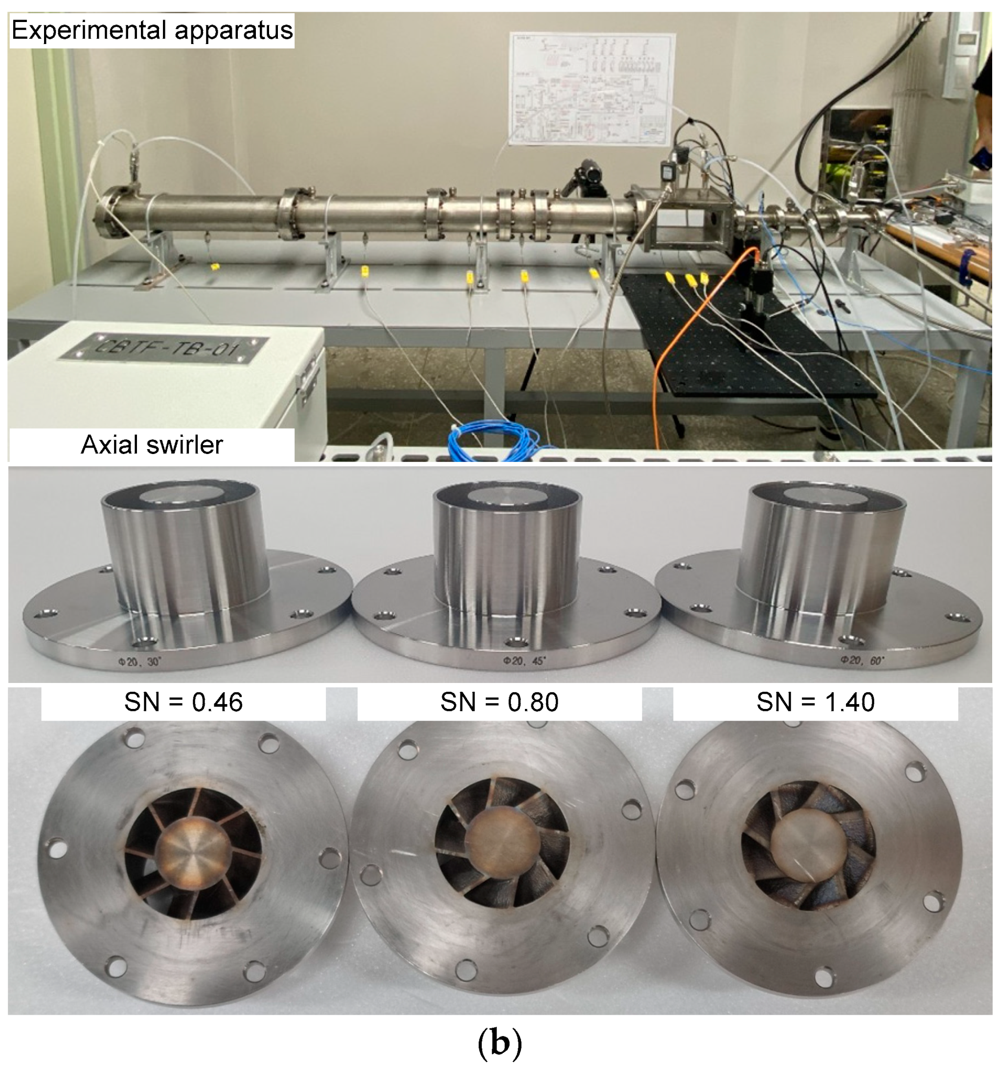
2.1. Experimental Setup and Instrumentation

Schematic and photographs of the swirl-stabilized combustor facility are shown in Figure 1. The swirl-stabilized combustor consisted of an inlet mixing section and a combustion chamber section. The distance between the dump plane and the choked plate was defined to be the length of the inlet mixing section (LI). It was 350 mm long and had a circular cross section with a diameter of 37.1 mm. The fuel and air were injected 35 mm downstream from the closed bottom of the inlet. Their mass flow rates were controlled using mass flow rate controllers (MKP, Hwaseong, Korea, VIC-D240/CAF-150, uncertainty ±1%/2.5%). A choked plate was installed 110 mm downstream of the inlet bottom to ensure perfect premixing. This also provided a well-defined acoustic boundary. Three flat-vane swirlers with vane angles of 30°, 45°, and 60° were used. The swirl numbers were calculated to be 0.46, 0.80, and 1.40, respectively [26]. They were mounted 66 mm upstream from the dump plane.
The combustion chamber was divided into two sections: a quartz window and flange-type part. The quartz window part had a square inner cross section of 95 mm × 95 mm. Its length was maintained at 215 mm. The quartz window allowed nonintrusive optical measurements to obtain the heat release rates and instantaneous flame structures. The flange-type part was connected to stainless steel pipes of various lengths with a diameter of 95.6 mm. A nozzle was used to achieve a closed acoustic boundary condition at the combustor exit. It had a circular inner diameter of 37 mm and blocked 85% of the chamber’s outlet area. The length of the combustion chamber (LC) was varied between 495 and 1695 mm at intervals of 100 mm.
Three piezoelectric dynamic pressure transducers (uncertainty ±1%) were flush-mounted 140 mm upstream ( p I n l e t ) and 30 mm downstream ( p C , 1 ) from the dump plane, and 60 mm upstream ( p C , 2 ) from the combustor nozzle to measure pressure fluctuations in the inlet mixing section and combustion chamber. The dynamic pressures were amplified using a signal conditioner (PCB Piezotronics, 482A16, Depew, NY, USA). Five pressure transducers (Sensys, Ansan, Korea, PHP, uncertainty ±0.035%) for the detection of static pressure were installed at each gas line and upstream of the choke plate. A photomultiplier tube (PMT, Thorlabs, Newton, NJ, USA, PDA100A-EC) coupled with a bandpass interference filter (435 ± 5 nm) was used to collect the heat release (CH* chemiluminescence) fluctuations from the entire flame surface. Several K-type thermocouples (uncertainty ±1.5 K) were utilized to obtain the bulk temperature in the chamber/inlet part and determine their resonant frequencies. The experimental data were recorded for NI-cDAQ for 1 s at a sampling rate of 10 kHz. A high-speed camera (Vision Research, Phantom v9.1) was used to acquire the instantaneous flame images. It was set to a sampling frequency of 4 kHz and an exposure time of 200 μs.

2.2. Experimental Conditions

The experimental conditions, including the geometric parameters and flow conditions, are listed in Table 1. Hot-firing tests with ethylene and methane were performed by independently varying the equivalence ratio (ϕ), inlet mean velocity (u, uncertainty ±2%), combustion chamber length (LC), and swirl number (SN, uncertainty ±2%). An equivalence ratio was chosen to exclude the effects of flame extinction and flashback for each fuel. The inlet mean velocity was selected to investigate the dynamic behavior of the turbulent lean premixed flames. The Reynolds number (uncertainty ±1.5%) was calculated from the inlet mean velocity, diameter of the axial swirler outlet, and temperature of the premixed gases.

3. Results and Discussion

3.1. Definition of Combustion Instability

To eliminate the direct current and noise components, the raw dynamic pressure and heat release data were digitally filtered using bandpasses with cut-off frequencies of 30 and 4000 Hz. Figure 2 shows the typical filtered data of the dynamic pressure and heat release in the combustion chamber section using C2H4 for LC = 495 mm, SN = 0.80, u = 10 m/s, and ϕ = 0.60 and 0.80. When the equivalence ratio was 0.60, the dynamic combustion characteristics exhibited fluctuations in the noise level without a special phase relationship between the dynamic pressure and heat release. In contrast, when the equivalence ratio was increased to 0.80, the dynamic pressure and heat release data were amplified several times and exhibited periodic behavior over time.
The power spectral densities of the filtered pressure fluctuations in the combustion chamber corresponding to the case shown in Figure 2 are shown in Figure 3. At ϕ = 0.60, the power spectral density did not exhibit a strong peak at a specific frequency. In contrast, the first longitudinal resonant frequency of the combustion chamber at approximately 200 Hz and its harmonic frequencies were visible at the higher equivalence ratio (ϕ = 0.80). In this study, a strong and steep peak in the power spectral density was observed when the RMS value of filtered pressure fluctuations in the combustion chamber ( p C , 1 ) was greater than approximately 2 mbar. Thus, an RMS value ( p R M S ) of 2 mbar based on p C , 1 was selected as the criterion for combustion instability.

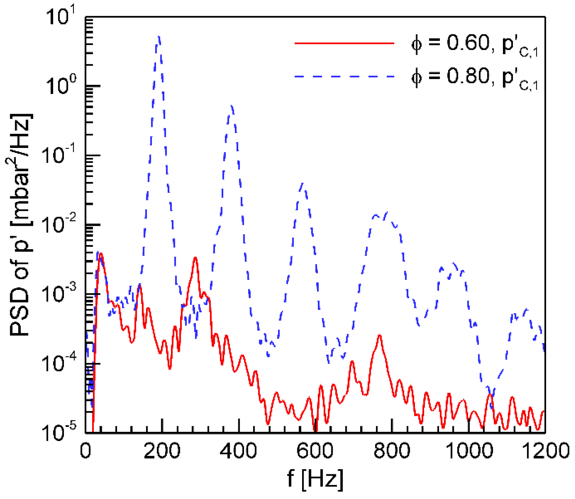
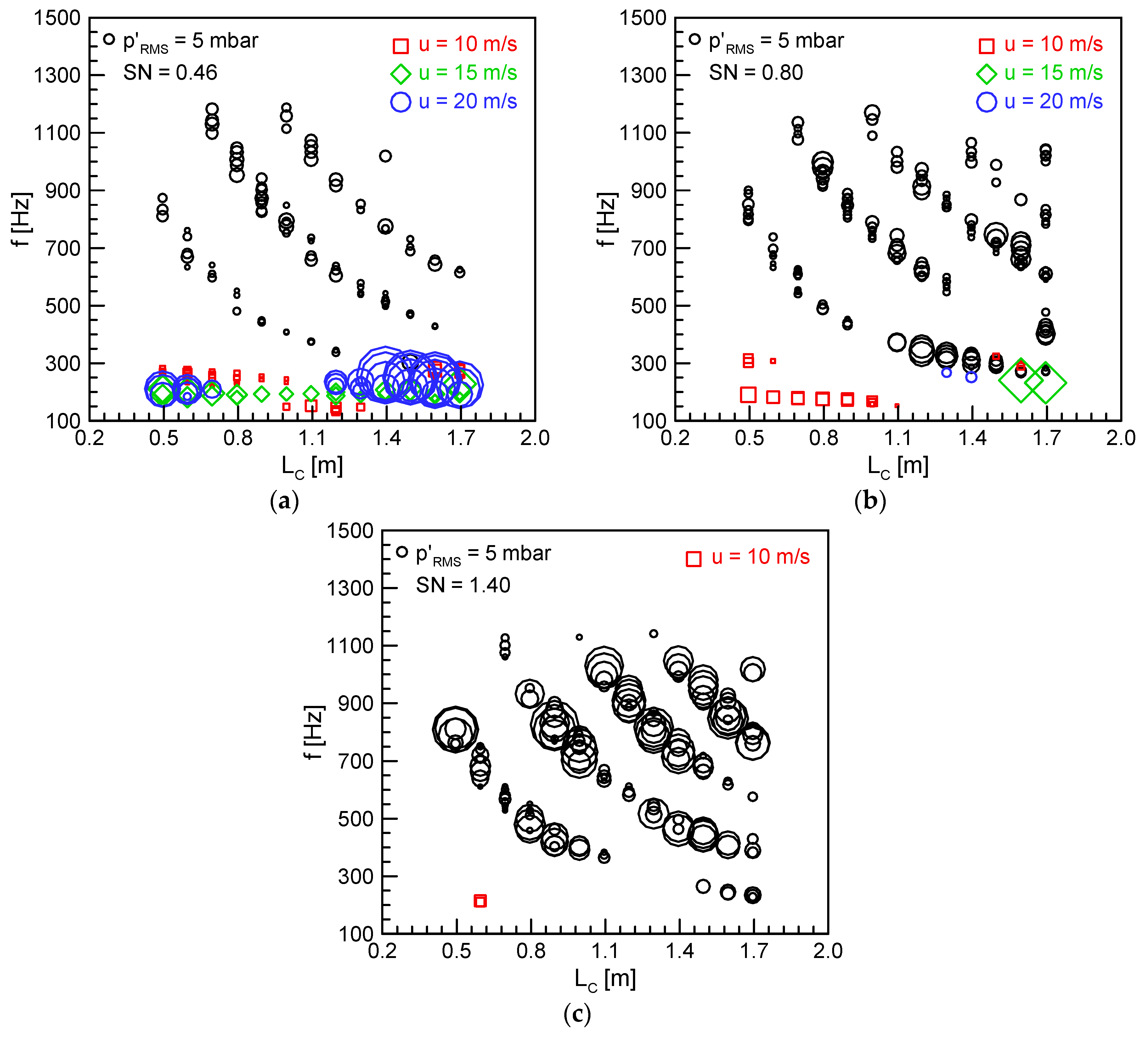
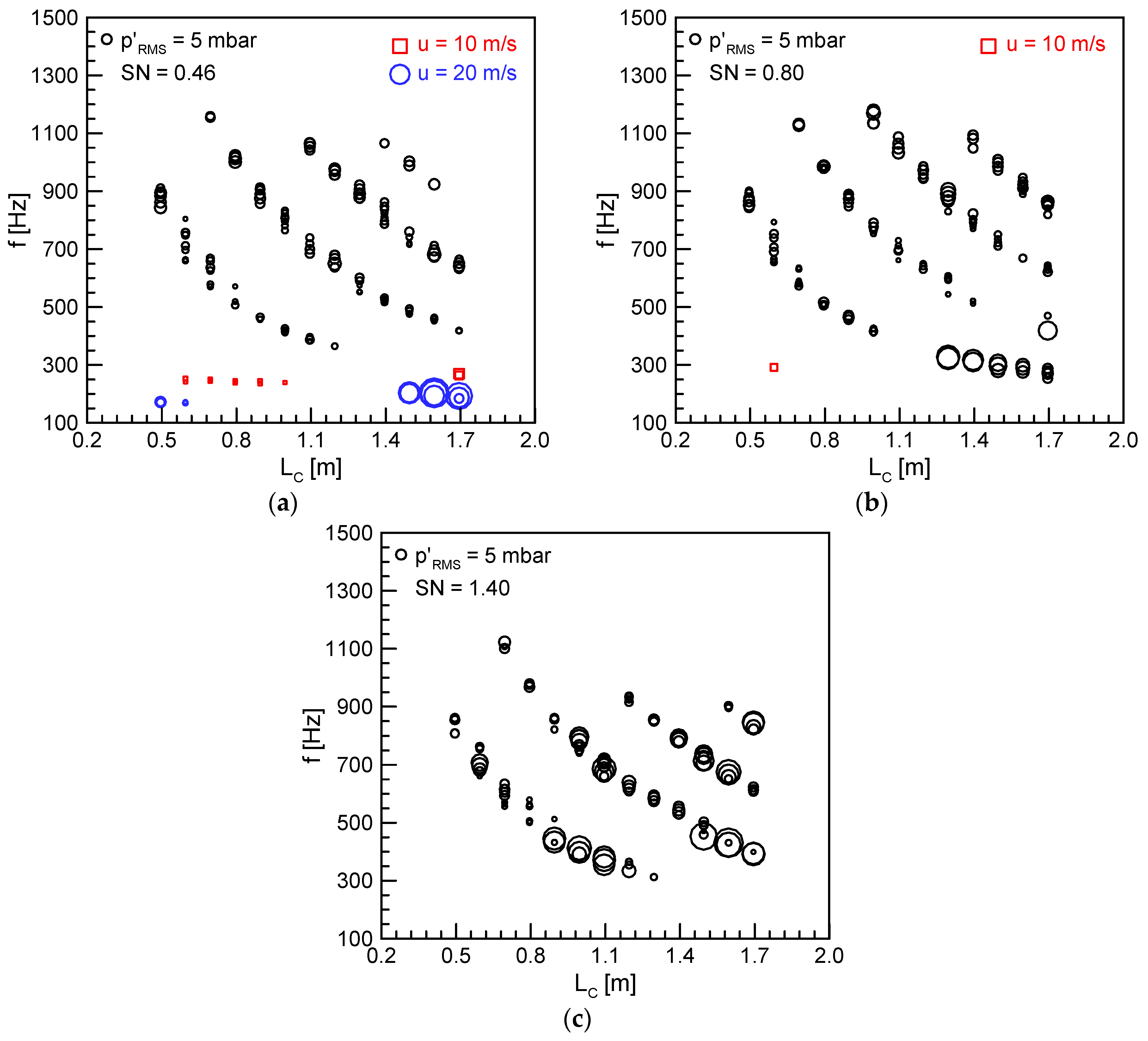
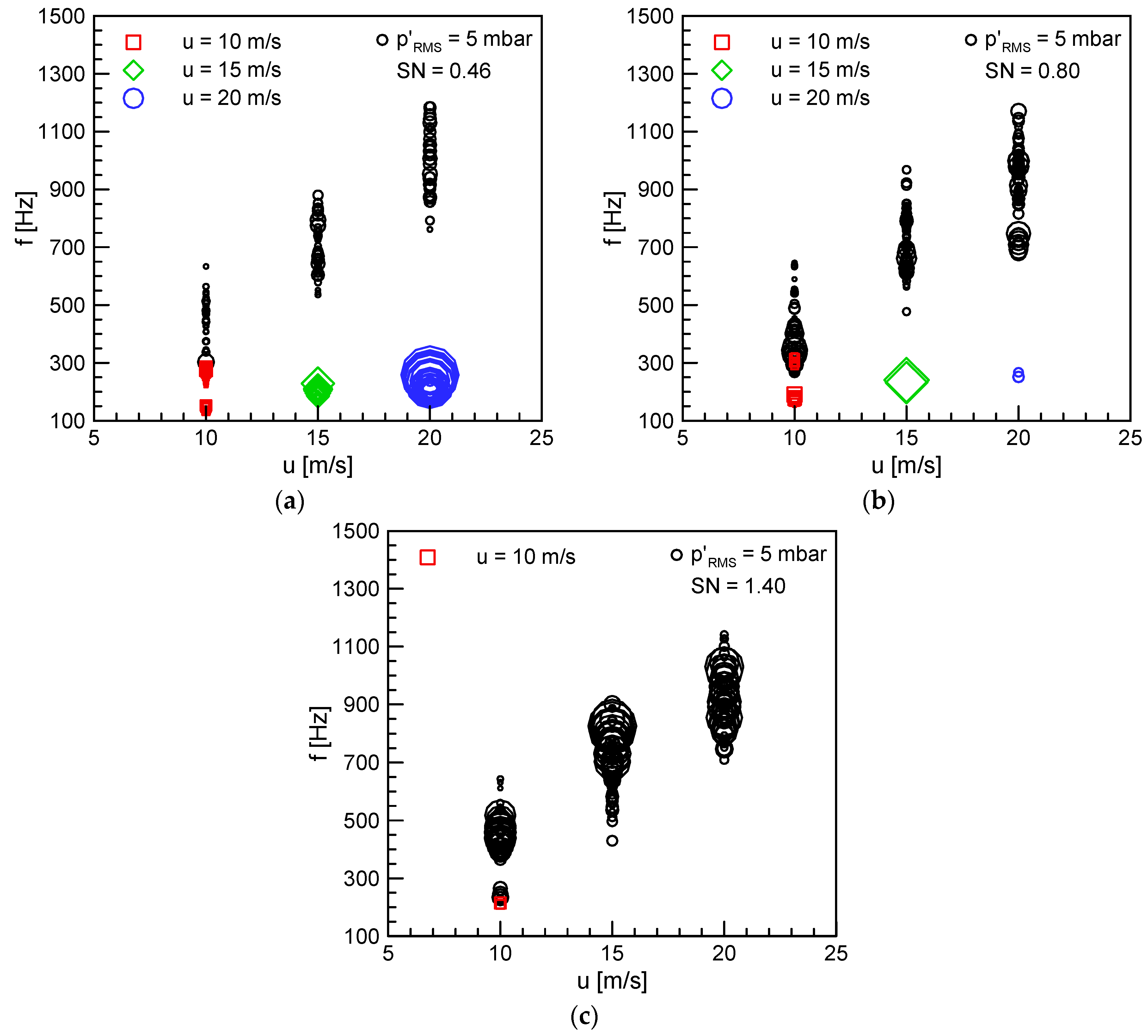
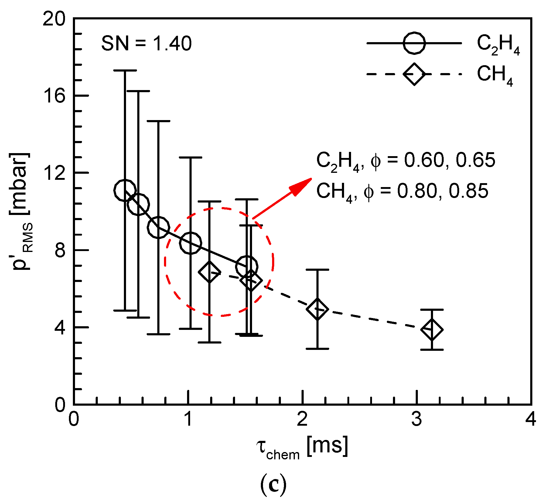
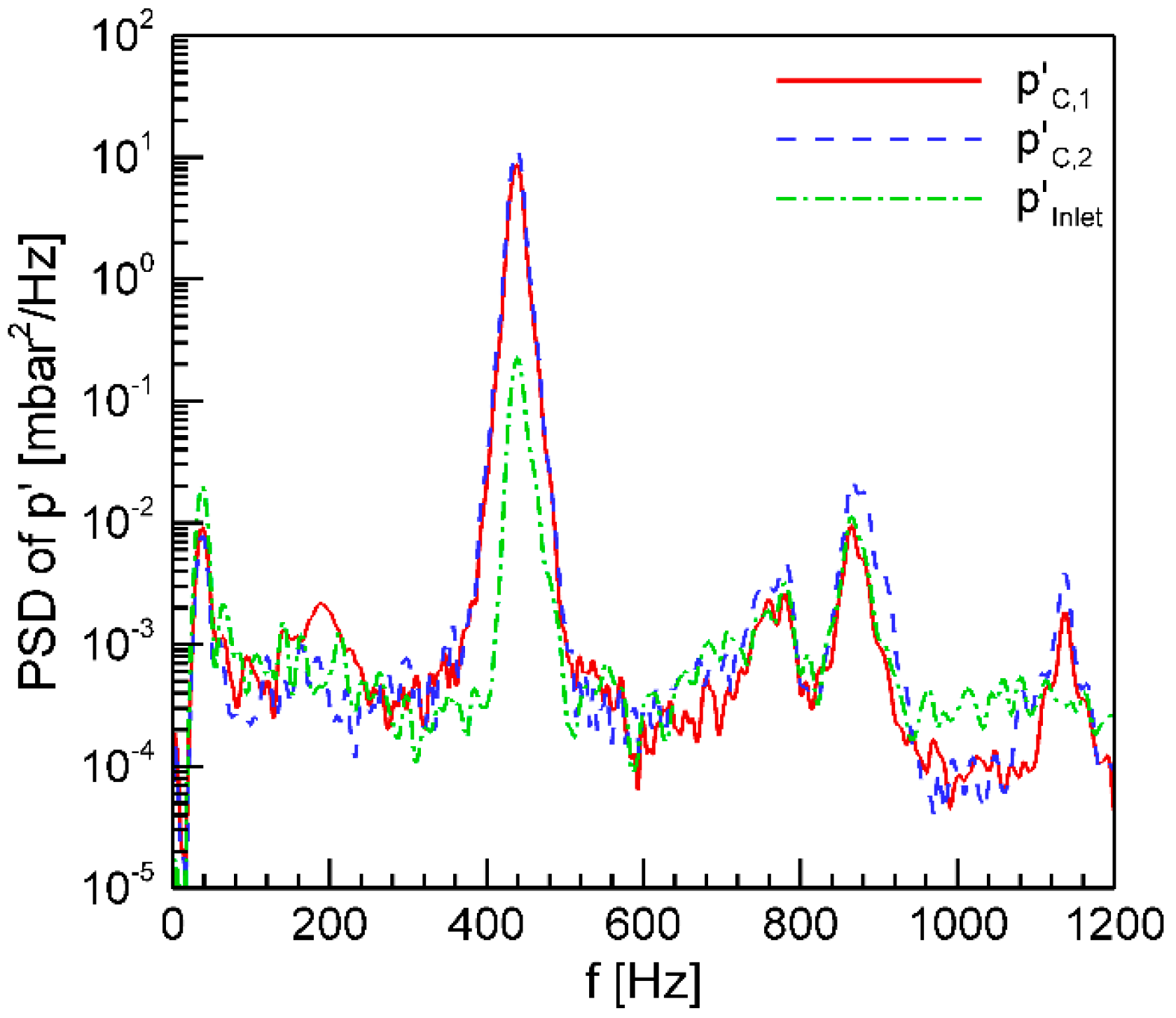
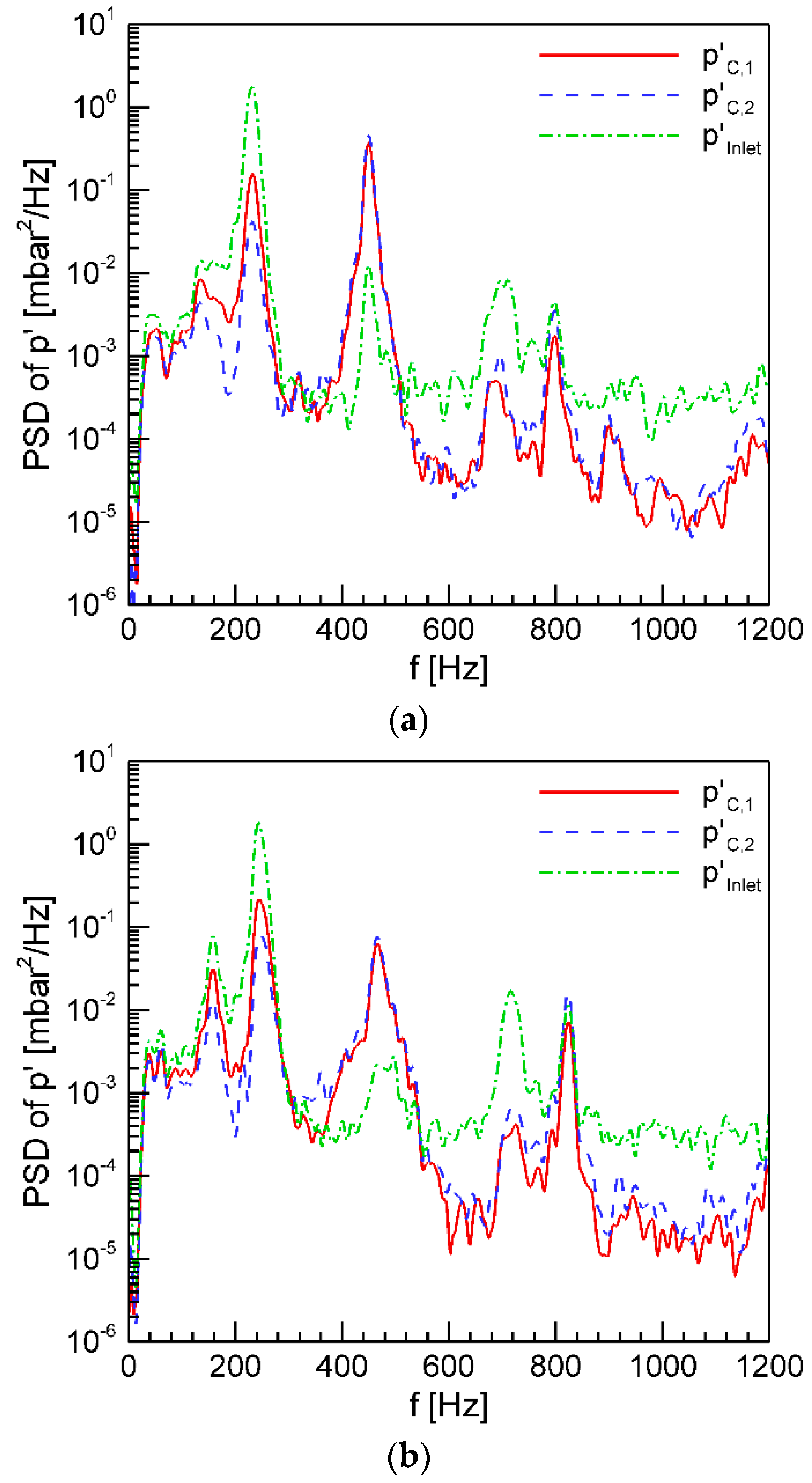
3.2. Analysis for Resonant Frequency in the Swirl-Stabilized Combustor

Figure 4 and Figure 5 show the dominant frequencies as a function of the combustion chamber length under all the experimental conditions using C2H4 and CH4, respectively. The results indicate only the cases in which combustion instability occurred, and the symbol sizes represent the relative amplitude of the pressure fluctuations in the combustion chamber. Two different resonant frequency bands were observed in the present study. The first was the eigenfrequency corresponding to the half-wave of the combustion chamber section, and the second was the quarter-wave eigenmode of the inlet mixing section. For theoretical analysis, the resonance frequencies corresponding to the chamber and inlet part were calculated using the one-dimensional standing wave theory as shown in Equations (1)–(3). The average temperature in the combustion chamber was assumed to be constant:
f h a l f w a v e = n c 2 L c
f q u a r t e r w a v e = ( 2 n 1 ) c 2 L I
c = γ R T
where n is the order, γ is the specific heat ratio, R is the gas constant, and T is the average temperature measured in the combustion chamber. In Figure 4 and Figure 5, the half-wave mode (black symbol) appeared in a wide frequency range, whereas the quarter-wave mode (color symbol) was concentrated in the lower-frequency band. The combustion instability modes associated with the half-wave of the combustion chamber responded to the modification of the combustor length. They were observed to be mainly coupled to their harmonic frequency rather than to the first longitudinal resonant frequency of the combustion chamber. In addition, the increase in SN generally induced pressure fluctuations with high amplitude.
In contrast, when the combustion system was coupled with the quarter-wave resonant frequency of the inlet mixing section, the dominant frequencies were independent of the combustion chamber lengths. The RMS values increased significantly when LC was between 1395 mm and 1695 mm. This is thought to be because the eigenfrequency of the inlet mixing section coincided with the first longitudinal resonant frequency in the combustion chamber section [21]. The increase in SN made the quarter-wave resonant mode disappear, which means that the acoustic wave of the inlet part was prevented from being transmitted to the combustion chamber and the entire combustion system was acoustically decoupled from the inlet mixing part. It is thought that a well-defined acoustic boundary was formed by the vane of the axial swirler at SN = 1.40. Figure 5 also shows similar trends; however, except for SN = 0.46, the quarter-wave eigenmode of the inlet mixing section was seldom observed.
The dominant frequencies and their RMS values, as summarized in Figure 4 and Figure 5, are plotted in Figure 6 and Figure 7, respectively, as a function of the inlet mean velocity. The inlet mean velocity and convection time are known to have a major influence on the mode shifting phenomenon [17]. As the inlet mean velocity increased, the half-wave resonant frequencies increased according to their harmonic frequencies; however, the quarter-wave resonant frequencies hardly changed. The results show that the acoustic response of the swirl-stabilized combustor could vary depending on the SN.
According to Hwang et al. [27], the dynamic combustion characteristics of the pressure oscillations showed consistent trends under similar characteristic chemistry times, regardless of the hydrocarbon fuel type. Figure 8 shows the effect of the characteristic chemistry times on the RMS values of the filtered pressure fluctuations under half-wave combustion instabilities. The characteristic chemistry time was determined as follows [28]:
τ c h e m = x S L
where x and SL are the flame thickness and the laminar burning velocity, respectively. These were calculated using the analytical equation proposed by Göttgens et al. [29]. This can provide important information for turbulent lean premixed flames from a qualitative point of view [27]. There was a deviation dependent on the flow condition under a fast characteristic chemistry time; however, the mean RMS values showed a decreasing trend in the characteristic chemistry time. In addition, the mean RMS values were almost the same, regardless of the fuels used at similar characteristic chemistry times. As a result, the experimental results of C2H4 could be quantitatively correlated with those of CH4, which helps to understand the importance of characteristic chemistry time for combustion instability coupled with the half-wave resonant mode of the combustion.
For a more in-depth analysis of the two different combustion instability characteristics, the power spectral densities of p C , 1 , p C , 2 , and p I n l e t were compared, as shown in Figure 9 and Figure 10. Figure 9 shows the power spectral density of the pressure fluctuations in the entire system when coupled with the combustion chamber section. There was one dominant peak at 438 Hz in the swirl-stabilized combustor. At SN = 1.40, when combustion instability occurred, only one peak amplitude was confirmed at one of the first longitudinal frequencies or its sub-harmonic frequencies in the combustion chamber. In contrast, at SN = 0.46, two visible peaks were observed, as shown in Figure 10a. Comparing Figure 10a with Figure 9, the frequency of the peak amplitude in the combustion chamber section nearly coincided with the case at SN = 1.40. However, in the inlet mixing section, the dominant frequency was measured as approximately 230 Hz. The reason for this was that two sinusoidal waves with different periods oscillated in the combustion chamber and the inlet mixing section. As shown in Figure 10b, the dominant frequencies in the combustion chamber shifted from 460 to 240 Hz at ϕ = 0.75. It is thought that the oscillating components with a high amplitude in the inlet mixing section had a significant effect on the combustion behavior of the entire system. This mode-shifting phenomenon is caused by a complete change in the combustion instability mode. In addition, the corresponding harmonics at 715 Hz were also observed in the inlet mixing section. The experimental results proved that the newly emerged frequencies of ~240 Hz at SN = 0.46 and 0.80 were due to the oscillation component corresponding to the quarter-wave eigenmode in the inlet mixing section.

3.3. Phase Analysis for the Combustion Instability Characteristics

Phase analysis for two different combustion instabilities provides new insights into combustion instability. Assuming that the combustion chamber section is acoustically closed at both ends by the dump plane and nozzle part, pressure antinodes are formed in the vicinity of the dump plane and nozzle. When the order of the half-wave resonance mode is odd (n = 1, 3, 5, ···) or even (n = 2, 4, 6, ···), the phase difference between each pressure fluctuation measured at both ends ( p C , 1 and p C , 2 ) is 180° and 0°, respectively. Figure 11 shows the phase difference between them at SN = 1.40. As discussed above, the swirl-stabilized combustor was acoustically coupled with the half-wave resonant frequency of the chamber with only two exceptions at SN = 1.40. Consequently, the phase difference between p C , 1 and p C , 2 was mostly concentrated at 0° or 180°, as shown in Figure 11a. However, in Figure 11b,c, because the combustion chamber mode was essentially indifferent to the mixing section acoustics, the pressure relationships between the pressure fluctuations in the chamber and the mixing sections were random features. Figure 12 shows the same trend regardless of the fuel type.
The inlet mixing section can be regarded as a closed–open type for a low SN. This means that an axial swirler with a low vane angle can be acoustically transparent [30]. In this case, as the acoustic wave with high amplitude traveled from the inlet mixing section to the combustion chamber section, the phase relationship between p I n l e t and p C , 1 / p C , 2 was established. Figure 13 illustrates the phase difference at SN = 0.46 as a function of the combustion chamber length. In the case of a half-wave, the phase difference was constant. However, the phase differences in the quarter-wave cases increased linearly with the increase in the combustion chamber length. The reason for this was that p C , 2 moved away from p C , 1 with increasing combustor length. Figure 13b shows the phase difference between p I n l e t and p C , 1 for the case of the quarter-wave resonant frequencies. Because the positions of the dynamic pressure sensors were fixed, the phase difference was constant. In Figure 13c, the phase difference exhibits a linear characteristic for the same reason as in Figure 13a. Compared to ethylene, the experimental results for methane corresponding to the eigenfrequency of the inlet mixing section were reduced, and the same trend is shown in Figure 14.

3.4. Flame Structure Characteristics for Two Different Combustion Instabilities

In the present swirl-stabilized combustor, two different combustion instability frequency modes were observed. Similarly, the flame structure also exhibited completely different characteristics in each mode. Instantaneous flame images for one period using C2H4 at LC = 795 mm, SN = 0.80, u = 20 m/s, and ϕ = 0.80 are presented in Figure 15. Here, the dominant frequency was 1046 Hz, which corresponded to the harmonic frequency of the half-wave coupled with the combustion chamber section. The left and right sides are the normalized and oscillating components, respectively. Based on the average intensity of the instantaneous flame images, the oscillating components were post-processed using red color for hot spots, blue for cold spots, and white for areas close to the average. This allows for a clearer identification of the relative heat release distribution and amplitude. Despite the phase change, all instantaneous images showed almost the identical structure and heat release pattern.
Figure 16 shows the flame structure and heat release pattern for the quarter-wave resonant frequency (200 Hz). The acoustic wave in the inlet mixing section induced a periodic flame with a large perturbation. At t = 0.00 ms, the width of the flame root was minimum. It gradually widened and then expanded to its maximum at t = 2.25 ms. In the process of shrinking again, large amounts of heat were dissipated in the downstream direction of the combustor. As a result, the acoustic wave of high amplitude in the inlet mixing section strongly oscillated the premixed reactants and induced heat release fluctuations. When the quarter-wave coupled to the inlet mixing section and the half-wave associated with the combustion chamber section had similar resonant frequencies, it was difficult to know which eigenmode dominated the entire combustion system from the phase analysis. In this case, the combustion instability mode could be identified using flame structures and their oscillation components.

4. Summary and Conclusions

An experimental study was performed to understand the characteristics of two different combustion instability modes in a swirl-stabilized combustor. The combustion instability modes in this study were classified into the half-wave resonance mode of the combustion chamber and the quarter-wave mode of the inlet mixing section. To understand their general characteristics, hot-firing tests were conducted by varying the flow (u and ϕ) and geometric conditions (LC and SN).
As SN increased, the entire combustion system was mainly coupled with the eigenmode of the combustion chamber, and their RMS values gradually increased. In contrast, at SN = 0.46, the combustion system often oscillated at the dominant frequency corresponding to the quarter-wave of the inlet mixing section. In this case, as the combustion chamber length increased, the RMS values exhibited a high amplitude because the eigenfrequency of the inlet mixing section coincided with the first longitudinal resonant frequency in the chamber section. The phase analysis of the two different combustion instability modes yielded interesting results. When the swirl-stabilized combustor was acoustically coupled with the half-wave of the combustion chamber, the phase difference between p C , 1 and p C , 2 was nearly concentrated at 0° and 180°. However, the phase relationship between the pressure fluctuations in the chamber and mixing section exhibited no special trends. In contrast, it possessed a linear characteristic between p I n l e t and p C , 2 and between p C , 1 and p C , 2 , or a constant characteristic between p I n l e t and p C , 1 for the quarter-wave of the inlet mixing section. Instantaneous flame structures and their oscillating components were analyzed in each instability mode. In the half-wave cases, the flame images showed almost the same structure regardless of the phase. However, in the quarter-wave cases, the width of the flame root periodically widened and narrowed according to the phase change. In this paper, the importance of the SN on combustion instability was emphasized. As a future work, a subject to be studied in detail will be how changes in the shape of the swirler (hub diameter, hub length, etc.) affect the combustion instability mode. Mode shape analysis based on low-order modeling will also be performed to verify the validity of the experimental results. It will be helpful for demonstrating the dependence of the swirl number on combustion instability in the swirl-stabilized combustor.

Author Contributions

D.H.: conceptualization, investigation, methodology, visualization, and writing—original draft. C.K.: data curation, formal analysis, visualization, and writing—review and editing. K.A.: formal analysis, funding acquisition, supervision, validation, visualization, and writing—review and editing. All authors have read and agreed to the published version of the manuscript.

Funding

This research was supported by the National Research Foundation (NRF–2021M1A3B8077772) and the Korea Aerospace Research Institute (KARI–FR21C00); and funded by the Ministry of Science, ICT, and Future Planning, South Korea. The authors thank MSIP and KARI for their support.

Conflicts of Interest

The authors declare no conflict of interest.

References

  1. Lefebvre Lean Premixed/Prevaporized Combustion; NASA CP-2016; Lewis Research Center: Cleveland, OH, USA, 1977.
  2. Foglesong, R.E.; Frazier, T.R.; Flamand, L.M.; Peters, J.E.; Lucht, R.P. Flame structure and emissions characteristics of a lean premixed gas turbine combustor. Jt. Propuls. Conf. Exhib. 1999, 2399. [Google Scholar] [CrossRef]
  3. Huang, Y.; Yang, V. Dynamics and stability of lean-premixed swirl-stabilized combustion. Prog. Energy Combust. Sci. 2009, 35, 293–364. [Google Scholar] [CrossRef]
  4. Ruan, C.; Chen, F.; Cai, W.; Qian, Y.; Yu, L.; Lu, X. Principles of non-intrusive diagnostic techniques and their applications for fundamental studies of combustion instabilities in gas turbine combustors: A brief review. Aerosp. Sci. Technol. 2019, 84, 585–603. [Google Scholar] [CrossRef]
  5. Wu, G.; Lu, Z.; Xu, X.; Pan, W.; Wu, W.; Li, J.; Ci, J. Numerical investigation of aeroacoustics damping performance of a Helmholtz resonator: Effects of geometry, grazing and bias flow. Aerosp. Sci. Technol. 2019, 86, 191–203. [Google Scholar] [CrossRef]
  6. Renaud, A.; Ducruix, S.; Zimmer, L. Bistable behaviour and thermo-acoustic instability triggering in a gas turbine model combustor. Proc. Combust. Inst. 2017, 36, 3899–3906. [Google Scholar] [CrossRef] [Green Version]
  7. Bernier, D.; Lacas, F.; Candel, S. Instability Mechanisms in a Premixed Prevaporized Combustor. J. Propuls. Power 2004, 20, 648–656. [Google Scholar] [CrossRef]
  8. Zhang, Z.; Zhao, D.; Han, N.; Wang, S.; Li, J. Control of combustion instability with a tunable Helmholtz resonator. Aerosp. Sci. Technol. 2015, 41, 55–62. [Google Scholar] [CrossRef]
  9. Chen, F.; Ruan, C.; Yu, T.; Cai, W.; Mao, Y.; Lu, X. Effects of fuel variation and inlet air temperature on combustion stability in a gas turbine model combustor. Aerosp. Sci. Technol. 2019, 92, 126–138. [Google Scholar] [CrossRef]
  10. Kim, K.T.; Santavicca, D.A. Interference mechanisms of acoustic/convective disturbances in a swirl-stabilized lean-premixed combustor. Combust. Flame 2013, 160, 1441–1457. [Google Scholar] [CrossRef]
  11. Rayleigh, J.W.S. The Theory of Sound, 2nd ed.; Dover: New York, NY, USA, 1945. [Google Scholar]
  12. Kim, K.T. Combustion instability feedback mechanisms in a lean-premixed swirl-stabilized combustor. Combust. Flame 2016, 171, 137–151. [Google Scholar] [CrossRef]
  13. Nicoud, F.; Poinsot, T. Thermoacoustic instabilities: Should the Rayleigh criterion be extended to include entropy changes? Combust. Flame 2005, 142, 153–159. [Google Scholar] [CrossRef] [Green Version]
  14. Venkataraman, K.K.; Preston, L.H.; Simons, D.W.; Lee, B.J.; Lee, J.G.; Santavicca, D.A. Mechanism of Combustion Instability in a Lean Premixed Dump Combustor. J. Propuls. Power 1999, 15, 909–918. [Google Scholar] [CrossRef]
  15. Huang, Y.; Yang, V. Bifurcation of flame structure in a lean-premixed swirl-stabilized combustor: Transition from stable to unstable flame. Combust. Flame 2004, 136, 383–389. [Google Scholar] [CrossRef]
  16. Yoon, J.; Kim, M.-K.; Hwang, J.; Lee, J.; Yoon, Y. Effect of fuel–air mixture velocity on combustion instability of a model gas turbine combustor. Appl. Therm. Eng. 2013, 54, 92–101. [Google Scholar] [CrossRef]
  17. Yoon, J.; Joo, S.; Kim, J.; Lee, M.C.; Lee, J.G.; Yoon, Y. Effects of convection time on the high harmonic combustion instability in a partially premixed combustor. Proc. Combust. Inst. 2017, 36, 3753–3761. [Google Scholar] [CrossRef]
  18. Allison, P.; Driscoll, J.F.; Ihme, M. Acoustic characterization of a partially-premixed gas turbine model combustor: Syngas and hydrocarbon fuel comparisons. Proc. Combust. Inst. 2013, 34, 3145–3153. [Google Scholar] [CrossRef]
  19. Park, J.; Lee, M.C. Combustion instability characteristics of H2/CO/CH4 syngases and synthetic natural gases in a partially-premixed gas turbine combustor: Part I—Frequency and mode analysis. Int. J. Hydrog. Energy 2016, 41, 7484–7493. [Google Scholar] [CrossRef]
  20. Schuller, T.; Durox, D.; Palies, P.; Candel, S. Acoustic decoupling of longitudinal modes in generic combustion systems. Combust. Flame 2012, 159, 1921–1931. [Google Scholar] [CrossRef]
  21. Kim, D.; Joo, S.; Yoon, Y. Effects of fuel line acoustics on the self-excited combustion instability mode transition with hydrogen-enriched laboratory-scale partially premixed combustor. Int. J. Hydrogen Energy 2020, 45, 19956–19964. [Google Scholar] [CrossRef]
  22. Kim, M.-K.; Yoon, J.; Oh, J.; Lee, J.; Yoon, Y. An experimental study of fuel–air mixing section on unstable combustion in a dump combustor. Appl. Therm. Eng. 2014, 62, 662–670. [Google Scholar] [CrossRef]
  23. Katsuki, M.; Whitelaw, J. The influence of duct geometry on unsteady premixed flames. Combust. Flame 1986, 63, 87–94. [Google Scholar] [CrossRef]
  24. Delacruzgarcia, M.; Mastorakos, E.; Dowling, A. Investigations on the self-excited oscillations in a kerosene spray flame. Combust. Flame 2009, 156, 374–384. [Google Scholar] [CrossRef]
  25. Hwang, D.; Ahn, K. Experimental Study on Dynamic Combustion Characteristics in Swirl-Stabilized Combustors. Energies 2021, 14, 1609. [Google Scholar] [CrossRef]
  26. Beer, J.M.; Chigier, N.A. Combustion Aerodynamics; Applied Science Publisher: London, UK, 1972. [Google Scholar]
  27. Hwang, D.; Song, Y.; Ahn, K. Combustion instability characteristics in a dump combustor using different hydrocarbon fuels. Aeronaut. J. 2019, 123, 586–599. [Google Scholar] [CrossRef]
  28. Sterling, J.D. Longitudinal Mode Combustion Instabilities in Air Breathing Engines; California Institute of Technology: Pasadena, CA, USA, 1987. [Google Scholar]
  29. Göttgens, J.; Mauss, F.; Peters, N. Analytic approximations of burning velocities and flame thicknesses of lean hydrogen, methane, ethylene, ethane, acetylene, and propane flames. Symp. Combust. 1992, 24, 129–135. [Google Scholar] [CrossRef]
  30. Kim, K.T.; Santavicca, D. Linear stability analysis of acoustically driven pressure oscillations in a lean premixed gas turbine combustor. J. Mech. Sci. Technol. 2009, 23, 3436–3447. [Google Scholar] [CrossRef]
Figure 1. Schematic (a) and photographs (b) of overall experimental apparatus.
Energies 15 08492 g001aEnergies 15 08492 g001b
Figure 2. Time histories of the pressure fluctuation data using C2H4 at LC = 495 mm, SN = 0.80, and u = 10 m/s: (a) ϕ = 0.60 and (b) ϕ = 0.80.
Energies 15 08492 g002aEnergies 15 08492 g002b
Figure 3. Power spectral densities corresponding to the cases in Figure 2.
Energies 15 08492 g003
Figure 4. Dominant frequencies and their RMS values as a function of combustion chamber length using C2H4: (a) SN = 0.46, (b) SN = 0.80, and (c) SN = 1.40.
Energies 15 08492 g004
Figure 5. Dominant frequencies and their RMS values as a function of combustion chamber length using CH4: (a) SN = 0.46, (b) SN = 0.80, and (c) SN = 1.40.
Energies 15 08492 g005
Figure 6. Dominant frequencies and their RMS values as a function of inlet mean velocity corresponding to the cases in Figure 4: (a) SN = 0.46, (b) SN = 0.80, and (c) SN = 1.40.
Energies 15 08492 g006
Figure 7. Dominant frequencies and their RMS values as a function of inlet mean velocity corresponding to the cases in Figure 5: (a) SN = 0.46, (b) SN = 0.80, and (c) SN = 1.40.
Energies 15 08492 g007
Figure 8. Effect of characteristic chemistry times on RMS values of half-wave pressure oscillation: (a) SN = 0.46, (b) SN = 0.80, and (c) SN = 1.40.
Energies 15 08492 g008aEnergies 15 08492 g008b
Figure 9. Power spectral densities of the filtered pressure fluctuations using C2H4 at LC = 895 mm, SN = 1.40, u = 10 m/s, and ϕ = 0.75.
Energies 15 08492 g009
Figure 10. Power spectral densities of the filtered pressure fluctuations using C2H4 at LC = 895 mm, SN = 0.46, and u = 10 m/s: (a) ϕ = 0.70 and (b) ϕ = 0.75.
Energies 15 08492 g010
Figure 11. Phase difference as a function of the combustion chamber length using C2H4 at SN = 1.40: (a) θ p C , 1 p C , 2 , (b) θ p I n l e t p C , 1 , and (c) θ p I n l e t p C , 2 .
Energies 15 08492 g011
Figure 12. Phase difference ( θ p C , 1 p C , 2 ) as a function of the combustion chamber length using CH4 at SN = 1.40.
Energies 15 08492 g012
Figure 13. Phase difference as a function of the combustion chamber length using C2H4 at SN = 0.46: (a) θ p C , 1 p C , 2 , (b) θ p I n l e t p C , 1 , and (c) θ p I n l e t p C , 2 .
Energies 15 08492 g013
Figure 14. Phase difference as a function of the combustion chamber length using CH4 at SN = 0.46: (a) θ p C , 1 p C , 2 , (b) θ p I n l e t p C , 1 , and (c) θ p I n l e t p C , 2 .
Energies 15 08492 g014
Figure 15. Representative instantaneous flame images (left) and their oscillating components (right) using C2H4 at LC = 795 mm, SN = 0.80, u = 20 m/s, and ϕ = 0.80.
Energies 15 08492 g015
Figure 16. Representative instantaneous flame images (left) and their oscillating components (right) using C2H4 at LC = 1195 mm, SN = 0.46, u = 15 m/s, and ϕ = 0.75.
Energies 15 08492 g016
Table 1. Experimental conditions.
OxidizerAir
FuelC2H4CH4
ϕ0.60–0.80, Δ0.050.70–0.85, Δ0.05
u [m/s]101520
Reynolds number24,00036,00048,000
LC [mm]495–1695, Δ100
LI [mm]350
Swirl number (SN)0.46, 0.80, 1.40
Publisher’s Note: MDPI stays neutral with regard to jurisdictional claims in published maps and institutional affiliations.

