Article

Research on Performance Optimization of Gravity Heat Pipe for Mine Return Air

1
School of Mechanical Electronic and Information Engineering, China University of Mining & Technology—Beijing, Beijing 100083, China
2
Beijing Zhongkuang Celebrate Energy Saving Technology Co., Ltd., Beijing 100085, China
*
Author to whom correspondence should be addressed.
Energies 2022, 15(22), 8449; https://doi.org/10.3390/en15228449
Submission received: 14 October 2022 / Revised: 4 November 2022 / Accepted: 9 November 2022 / Published: 11 November 2022
(This article belongs to the Special Issue Advanced Heat Transfer and Energy Saving Technology)

Abstract

:
The mine return air flow has the characteristics of basically constant temperature and humidity all year round and is a high-quality waste heat resource. Its direct discharge not only wastes energy but also causes environment pollution. It has important economic value and application prospect to solve the problem of shaft antifreeze using new technology to recover the waste heat of mine return air. Gravity heat pipe is widely used in the heat recovery of mine return air. Its heat transfer process is a complex process with multiple parameters. The current research focuses on the influence of a single factor on heat transfer, which has many limitations. To analyze the effects of different parameters on the heat recovery effect of gravity heat pipe in mine return air and to optimize heat pipe heat exchanger parameters in the heat exchange system, mathematical models of gas–water countercurrent heat and mass transfer, entransy dissipation and exergy efficiency were established in this paper, based on the entransy dissipation theory. Under the condition of the given initial parameters, the effects of different parameters on the dimensionless factor, β, of heat transfer, total heat transfer, and entransy dissipation thermal resistance were analyzed. The experimental and calculation results show the entransy dissipation theory can be used to evaluate the heat transfer performance of the gravity heat pipe. When the entransy dissipation thermal resistance was minimum, the heat transfer performance was optimal. During the heat transfer process between the mine return air and the gravity heat pipe with high humidity under a given working condition, increasing the Reynolds number was beneficial to increase the heat transfer dimensionless factor, β.

1. Introduction

The mine return air flow temperature and humidity are basically constant all year round, which is a high-quality waste heat resource. Its direct discharge not only wastes energy but also causes environment pollution. Under the background of phasing out coal-fired boilers in mine heating and seeking more energy-saving heating solutions, it has become an urgent problem to solve the problem of wellbore antifreeze by recovering the residual heat of the mine return air through new technologies [1].
In recent years, domestic and foreign scholars have conducted much theoretical, experimental, and applied research on heat recovery technology, such as spray heat transfer [2,3], partition heat extraction [4], and gravity heat pipe heat transfer technology [5,6]. At present, the gravity heat pipe has significant technical advantages in solving the problem of wellbore antifreeze due to its unpowered heat transfer.
Today, there have been more than 20 domestic applications of gravity heat pipe in mine return air heat recovery engineering with the accumulation of gravity heat pipe technology. Many methods, such as parameter optimization, thermodynamic optimization, and experimental analysis, have been adopted to improve the gravity heat pipe’s heat transfer performance in mine heat recovery system. Some scholars used FLUENT software to simulate the heat pipe heat exchange system under high humidity conditions [7,8]. Zhang et al. [9] established a heat transfer model between fins and water film for the condensation heat transfer of non-condensable gases and analyzed the influence law of single parameter on the heat and mass transfer effect with the MATLAB numerical iterative solution. Some researchers [10,11,12,13] carried out actual engineering analysis, discussing the heat transfer efficiency of heat pipe under the typical parameters. Since the heat exchange process between the mine return air and the gravity heat pipe involves the heat and mass transfer process between the non-condensable gas and the pipe wall, and the convective heat transfer process inside and outside the pipe as well, it is a complex process affected comprehensively by multiple parameters. Hence, it has certain limitations that the parameters of gravity heat pipe are optimized through the investigation of the influence law of single factor on heat transfer under the condition that other parameters remain unchanged.
To reduce the energy loss of the evaporative cooling system, the literature [14,15] built a model of exergy efficiency and optimized the gas–water heat and mass transfer process. Some scholars [16,17,18] questioned the applicability of the minimum exergy loss principle (or minimum entropy production principle) to evaluate all heat and mass transfer processes. To analyze and optimize the heat transfer process which did not involve the heat–work conversion, Guo et al. [19] proposed a physical quantity of entransy describing the heat transfer capability of an object based on the similarity of a thermal conduction process and an electrical conduction process and used entransy dissipation to measure the heat transfer capability. The irreversibility of a heat transfer loss proves that the entransy dissipation optimization principle is independent with heat–work conversion and has been successfully applied to optimize heat conduction [20,21], thermal convection [22,23,24], and coupled heat and mass transfer [25,26,27,28,29,30]. The literature [31] defined the entransy dissipation thermal resistance and derived the entransy dissipation thermal resistance expression, namely the ratio of the entire entransy dissipation to the square of the heat flow.
To optimize the performance of the gravity heat pipe, this paper introduces the analysis of entransy dissipation heat resistance, establishes the heat and mass transfer model of the gravity heat pipe, and sets up an experimental platform. Through numerical simulation and physical experiments, the heat transfer law of high-speed, high-humidity air and the gravity heat pipe under low-temperature conditions is analyzed. A method for optimizing the parameters of the heat transfer unit of the gravity heat pipe is proposed, which provides a fresh research method and theoretical basis for optimizing the performance of the heat exchange unit of the heat pipe.

2. Mathematical Model in Vertical Spray Chamber
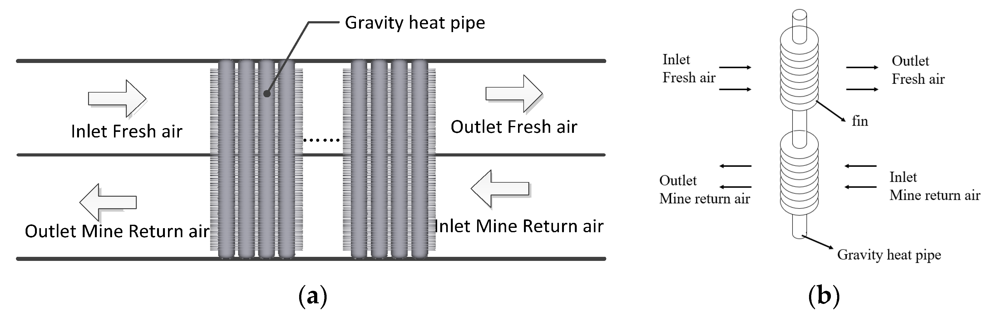
2.1. Physical Model

The gravity heat pipe heat transfer model is shown in Figure 1a, which presents the heat exchange process between the gravity heat pipe and the mine return air. The model consists of two separate ventilation channels and gravity heat pipe. The upper layer is an outdoor fresh air channel in which a cold fluid is to be heated and the lower layer is a mine return air channel in which a hot fluid is to be cooled. The heat transfer mode of the two channels is countercurrent heat transfer. The evaporation side of the gravity heat pipe absorbs the waste heat of the mine return air, and the heat is transferred to the condensing side of the gravity heat pipe through the phase transition of the working medium in the pipe to complete the heat transfer. Figure 1b illustrates the structure of a gravity heat pipe. Fins are arranged on the outer walls of the evaporation section and the condensation section of the heat pipe to improve the heat transfer effect of the heat exchanger. Due to the large moisture content of the mine return air, a condensate film condensed by water vapor will be generated on the outer wall of the heat pipe at the return air side of the heat exchanger and on the surface of the fins; thus, the mine return air is under a wet condition while the fresh air at the fresh air side of the heat exchanger is under a dry condition. The heat transfer resistance in the tube may be neglected as it is quite small.

2.2. The Model of Heat and Mass Transfer

The heat, Qc, absorbed by the cold fluid is:
Q c = m c c p , e ( t c , out t c , in )
where mc is the mass flow rate of the cold fluid (kg/s) which is the product of cold fluid density, ρc (kg/m3), and cold fluid velocity, uc (m/s), mc = ρcuc; cp,e is the constant pressure specific heat of the fluid (kJ·(kg·K)−1); tc is the temperature of the cold fluid. The subscripts in and out represent the inlet and the outlet of the cold fluid, respectively.
The heat Qe released by the thermal fluid is:
Q e = m e ( h e , in h e , out )
where me is the mass flow rate of the hot fluid (kg/s) which is the product of hot fluid density, ρe (kg/m3), and hot fluid velocity, ue (m/s), namely me = ρeue, h is the enthalpy of the hot fluid (kJ·(kg)−1), and the subscripts in and out represent the inlet and the outlet of the hot fluid, respectively.
The assumptions are made in the row-by-row calculation process of the gravity heat pipe in the mine return air: The Lewis relation is established, Le = 1. The heat pipe heat exchange unit is composed of 10 heat exhaust pipes, and the heat Qi transmitted by the ith gravity heat pipe can be calculated by the following formula:
Q i = U c , i A c , i ( t c t we , i ) = U e , i A e , i ( h e , i h e , i + 1 )
where Uc,i and Ue,i represent the heat transfer coefficients of the condensation section and the evaporation section of the ith gravity heat pipe, respectively; Ac,i and Ae,i represent the heat-exchange areas of the condensation section and the evaporation section of the ith gravity heat pipe, respectively; twe,i is the wall temperature of the ith pipe.
Pirompugd et al. [32] further developed the finite circle fin method on the basis of the Threlkeld method and proposed the pipewise analysis method to calculate and sort the data of heat and mass transfer characteristics of the finned pipe heat exchanger under dehumidification conditions. According to the Threlkeld method, the heat transfer equation on the return air side based on enthalpy difference is
Q = U 0 A 0 ( i e i c )
where U0 is the heat transfer coefficient based on enthalpy difference; A0 is the total heat transfer area of the heat pipe evaporator (m2); ie and ic are respectively the enthalpy values of return air and fresh air, which can be calculated by the following formulas:
i e = i e , in + ( i e , in i c , out ) ln ( i e , in i c , out ) ( i e , out i c , in ) ( i e , in i e , out ) ( i e , in i c , out ) ( i e , in i c , out ) ( i e , out i c , in )
i c = i c , out + ( i c , out i c , in ) ln ( i e , in i c , out ) ( i e , out i c , in ) ( i c , out i c , in ) ( i e , in i c , out ) ( i e , in i c , out ) ( i e , out i c , in )
where ie,in and ie,out are the enthalpy at the inlet and the outlet of the return air side (kJ/kg), respectively; ic,in and ic,out are the saturated air enthalpy under the temperature at the inlet and the outlet of the fresh air side (kJ/kg), respectively.
Taking the evaporation side of the heat pipe as the base pipe for calculation, the relationship between the total heat transfer coefficient based on enthalpy difference and the thermal resistance of each part of the heat exchanger is as follows:
1 U 0 A 0 = R 1 b 1 + R 2 b 2 + R 3 b 3 + R 4 b 4
where R1 and R4 are the external convection heat transfer resistances of the pipe at the return air side and the fresh air side, respectively; R2 and R3 are the thermal resistances of the pipe wall in the evaporation section and the condensation section of the heat pipe, respectively; b1 is the slope of the saturated air curve at the outer wall temperature of the evaporation section of the heat pipe; b2, b3, and b4 are the ratios of the temperature saturated air enthalpy difference and temperature difference at the inner and outer side wall of the evaporating section of the heat exchanger, the inner and outer side wall of the condensing section of the heat exchanger, and the outer wall and fresh air of the condensing section of the heat pipe, respectively. Equation (7) can be converted into:
1 U 0 = b 1 A 0 h r ( A e , w + η f , wet A e , f ) + b 2 A 0 ln ( d 1 / d 0 ) 2 π λ b l e + b 3 A 0 ln ( d 1 / d 0 ) 2 π λ b l c + b 4 A 0 h a ( A c , w + η f A c , f )
where ηf,wet and ηf represent the heat transfer efficiencies of gravity heat pipe fins under the wet and dry conditions, respectively; hr and ha represents the sensible heat transfer coefficient and the total heat transfer coefficient of the pins at the return air side, respectively; dl and d0 are the outer diameter and inner diameter of the fin pipes respectively.
The saturated air enthalpy, iw,m, at the average temperature of the water film, Tw,m, can be iteratively achieved by the following equation:
i w , m = i e C p a h r η f , wet b 1 h s · ( i e i c ) × ( 1 U 0 A 0 ( ( b 2 + b 3 ) ln ( d 1 / d 0 ) 2 π λ b l + b 4 h a ( A c , w + η f A c , f ) ) )
where hs is the latent heat transfer coefficient of the pins at the return air side.
According to the research of Bump et al. [33], the ie and ic values are calculated by the average enthalpy difference method. This paper refers to the reference for calculation, which solves the heat transfer of the pipe-fin heat exchanger under wet conditions and obtains the corrected heat transfer efficiency.

3. Thermodynamics Analysis of Heat and Mass Transfer

3.1. Exergy Analysis

The thermal exergy and the humid exergy of humid air at standard atmospheric pressure can be expressed by the following formula [9]:
E x , a ( T , ω ) = ( C p , a + ω C p , v ) ( T T 0 T 0 ln T T 0 ) + R a T 0 ( ( 1 + 1.608 ω ) ln 1 + 1.608 ω 1 + 1.608 ω 0 + 1 + 1.608 ω ln ω ω 0 )
where cp,v is the specific heat at constant pressure of water vapor, 1.872 kJ/(kg·K); Ra is the gas constant for dry air, 0.287 kJ/(kg·K), ω is the moisture content of wet air, and T is the dry bulb temperature of wet air. Wet air exergy takes the ambient temperature, T0, and saturated moisture content, ω0, at ambient temperature as the reference point [15].
The countercurrent heat transfer of moist air in the gravity heat pipe heat exchange unit can be regarded as an adiabatic process with stable flow and without power output. The exergy loss, Xdes, can be expressed as the difference between the input exergy, Xi, from the mine return air and outdoor inlet air and output exergy, X0. Therefore, the exergy balance equation is expressed by:
X des = X i X o = ( X e , i X c , i ) ( X e , o X c , o )
where Xe is the exergy value of return air status point, Xc is the exergy value of fresh air status point, and the subscripts, i and o, are the status points of inlet and outlet, respectively.
The definition of exergy efficiency for the system of humidity wet air can be expressed as Equation (10), which will yield a value between 0 and 1 [14].
η e x = X e , 0 + X c , 0 X e , i + X c , i

3.2. Entransy Analysis

The entransy describes the heat transfer ability of an object and can be expressed by [26]:
J a i r ( T , ω ) = 1 2 G c p , a ( T a T 0 ) 2 + G γ ( ω a ω 0 ) ( T a , d p T 0 )
where Jair represents the heat and mass transfer ability of moist air at ambient temperature, γ is the gasification latent heat of air, Ta,dp is the dew point temperature of air. Then, the total entransy dissipation equation is [21]:
J des = J airh , in J airh , out + J airc , in J airc , out
where Jdes is the entransy dissipation of the heat transfer process, Jairh is the entransy at the point of the hot side, Jairc is the entransy at the point of the cold side, and the subscripts of in and out are the inlet and outlet state points, respectively.
During the process of heat and mass transfer, the entransy dissipation thermal resistance, R, [28] can be express as the total entransy dissipation rate divided by the squared refrigerating effect, Q2, as the following formula:
R = J des / Q 2

4. Materials and Methods

4.1. Experiment Equipment

As shown in Figure 2, the experiment equipment mainly includes three parts: air pretreatment section, countercurrent heat exchange unit of gravity heat pipe, and PLC measurement and control system.
(1)
Air pretreatment section
The main function of the air pretreatment section is to simulate the wet air parameters in winter.
(2)
Gravity heat pipe heat exchange unit
The basic parameters of the gravity heat pipe heat exchange unit are listed in Table 1.
(3)
PLC measurement and control system
The control system is composed of frequency converter, PLC controller, and touch screen. Four temperature measuring points and two humidity measuring points are arranged at the air inlet and outlet, respectively. The temperature and the humidity are measured by the digital high-precision measuring instrument, testo 635, with a temperature measurement accuracy of ±0.05 °C and a humidity measurement accuracy of ±2%. Wind speed is measured by Pitot tube wind speed sensor, W410A4, with an accuracy of ±0.1 m/s.
(4)
Parameters of gravity heat pipe
The parameters of gravity heat pipe are shown in Table 2.

4.2. Model Validation

To verify the model accuracy, we conducted an experiment. The experimental parameters, experimental results, and numerical calculation results of the model are listed in Table 3 in which the experimental data are the average value of 10 measurements under stable conditions.
With the experimental data, the heat absorbed by the condensation section, Qc, and the heat released by the evaporation section, Qe, are calculated by the formula in Section 2, and the relationship diagrams of Qc and Qe are drawn, as shown in Figure 3, in which the two red dash lines are the 6% shift to the red solid line of Qc = Qe. Four groups of the heat Qe released by the evaporation section and the heat Qc absorbed by the condensation section obtained by experiments are listed in Table 4, which also gives the heat exchange, Qr, calculated using the model. It can be seen from Figure 3 and Table 4 that the error between Qc and Qe fluctuates within ±6%, and the error of Qc or Qe and Qr within 4%, which indicates the validity of the experimental data and the established model.

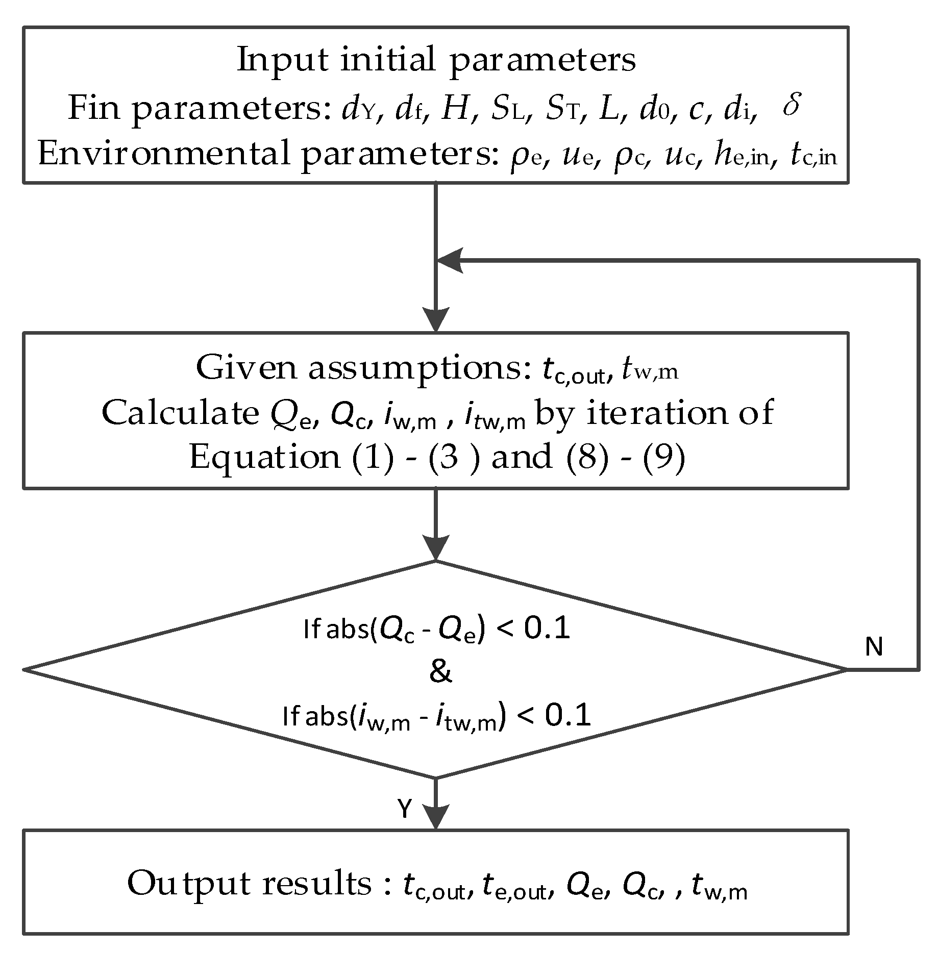
5. Calculations and Solution

The actual engineering of gravity heat pipe is under the condition of given air volume at the heat source and cold source side, temperature of the heat source, and humidity. At present, the gravity heat pipe widely applied in the projects has low heat recovery efficiency in the coalmine in China; thus, it is necessary to optimize the parameters of the gravity heat pipe heat exchange unit. In this paper, the optimization process is introduced by taking the gravity heat pipe heat exchange engineering of a mine as an example. The engineering parameters are as follows: return air temperature of 18 °C, return air inlet relative humidity of 90%, and outdoor inlet air temperature of −28 °C (extreme weather). Table 5 gives the initial parameters of the gravity heat pipe fins. Through the iterative solution of Equations (1)–(5), by setting the initial values of the cold side outlet air temperature and water film temperature, the values obtained by calculating the heat exchange on the cold side and the hot side were compared. When the set initial value was within the error range of 0.1 kW, the true value of the outlet air temperature on the cold side and the calculated value of the outlet air temperature on the hot side are obtained. Based on those, the heat transfer situation of the single-row heat pipe heat exchanger can be iteratively solved. The optimized progress is illustrated in Figure 4.

5.1. The Effect of Fin Spacing, dY, and Outer Diameter, df, on Heat Transfer

The dimensionless number, β, is the ratio of Nussel number, Nu, Reynolds number, Re, and Prandtl number, Pr, which can be expressed by Equation (13), representing the degree of synergy between the velocity field and the convection field in the heat transfer process of the fluid. Generally, to improve the heat transfer capacity of the heat exchanger, a single increase of disturbance to enhance the convection heat transfer will increase the flow loss, which will reduce the overall performance. Therefore, the comprehensive effects of friction factor and heat transfer factor should be considered simultaneously through the field synergy theory.
β = Nu / Pr Re
Given the other parameters, the effect on the heat transfer process was analyzed by changing the fin gaps on the evaporation and condensation sides. Figure 5 shows the effect of the fin’s parameters of dY, df and the wind speed at different sections on the dimensionless coefficient, β, and heat transfer coefficient under dry conditions. It can be seen from Figure 5 that the increase of fin outer diameter is conducive to the increase of heat transfer coefficient. Due to the formation of eddy currents, the distribution of the airflow velocity field and the temperature field became increasingly unstable, which made the synergy worsen and the overall performance decreased.
Figure 6 shows the effects of different fin parameters of dY, df and the cross-sectional wind speed on the dimensionless coefficient, β, and the heat transfer coefficient under wet air condition. It can be seen from Figure 6 that under the wet working condition, when other conditions remain unchanged, the heat transfer coefficient increases when the fin spacing and section wind speed are increased; the heat transfer coefficient first increases and then decreases when the fin height is increased. Under the high humidity condition, the condensed water is attached to the fin wall, and there is contact thermal resistance between the wet air and the wall. Therefore, when designing the return air and evaporation side of the mine, the fin spacing cannot be infinitely reduced, and the fin height cannot be increased too much.
Based on the above analysis, we can conclude that the influence law of fin parameters on heat transfer coefficient is different under the dry condition and under the wet condition. Under the dry condition, the heat transfer coefficient decreases with the increase of fin spacing and increases with the increase of fin height. However, under the wet condition, the heat transfer coefficient increases with the increase of fin spacing and first increases and then decreases with the increase of fin height.

5.2. Effect of Return Air Volume on Heat Transfer

This section aimed to improve heat transfer capacity based on calculation of actual engineering cases. Figure 7 is an engineering drawing of the gravity heat pipe heat exchange project in a mine. The basic parameters of the mine were designed as: return air temperature of 18 °C, return air inlet relative humidity of 90%, and 18 gravity heat pipe heat exchange devices. Table 5 shows the fin initial parameters of the mine gravity heat pipe.
Figure 8 shows the heat transfer of gravity heat pipes in different tube rows. By analyzing the heat exchange process of each row of heat pipes, the change rules of the fresh air temperature, water film temperature, and heat transfer and heat transfer resistance passing through each row of heat pipes can be obtained clearly.
It can be seen from Figure 8 that the larger the inlet air volume, the lower the fresh air outlet temperature. When the air volume reached 888 m3/min, the fresh air outlet temperature was lower than 0 °C, and the water film temperature was close to 0 °C. When the intake air volume continued to increase, the water film temperature was lower than 0 °C, which may bring a risk of freezing. Figure 8c,d shows that when the air intake was larger, the heat exchange was larger, and the heat exchange thermal resistance was smaller. When the number of tube rows increased, the heat transfer thermal resistance increased. When the number of tube rows increase, the temperature of fresh air outlet decreases, and the temperature of water film decreases which increases the risk of icing, and the heat transfer resistance increases significantly. However, when the air inlet volume increases to a certain value and the heat exchange rate does not increase significantly with the increase of the number of tube rows, the thermal resistance increases greatly. Therefore, there is a reasonable range to obtain the opt effect of heat transfer.
In summary, an increase of Reynolds number is conducive to improving the quantities of heat exchange and reducing heat transfer resistance, but it will also reduce the temperature of the fresh air outlet and the water film temperature on the surface of the end row heat exchanger, increasing the risk of icing.

5.3. Thermal Analysis of Gravity Heat Pipes

According to the experimental results of the heat pipe heat transfer in Table 6, the calculation results of the thermodynamic evaluation parameters of the gravity heat pipe heat exchange system are obtained. Through the comparative analysis of heat exchange, exergy efficiency, and entransy heat dissipation resistance, it was found that when the heat exchange is maximum, the entransy heat dissipation resistance is minimum, while the exergy efficiency is the lowest, which is consistent with the literature [21]. Thus, there is a certain deficiency in the applicability of exergy efficiency in evaluating the efficiency of a heat exchanger that does not involve thermal-work conversion. From the analysis of the experimental calculation results, it can be seen that compared with the exergy efficiency, the entransy heat dissipation resistance is more instructive to evaluate the irreversible thermodynamic heat transfer process that does not involve thermal-work conversion.

6. Conclusions

To optimize the performance of the gravity heat pipe, the proposed optimized water–air ratio calculation method was analyzed and verified by analyzing the influence of different fin parameters on the dimensionless coefficient, β, and heat transfer coefficient at different cross-sectional wind speeds and based on the evaluation index of the second law of thermodynamics. The following conclusions were obtained.
A gravity heat pipe heat transfer model was established, and an experiment platform for heat pipe heat transfer was built. The error between the numerical calculation results and the experimental results was approximately 6%.
Under the given working condition, the influence of different fin parameters on the heat transfer coefficient and the dimensionless coefficient, β, was compared and analyzed in dry and wet air conditions, and the optimized fin parameters were obtained. Different from the dry air condition, in the wet air condition, there was a reasonable value of fin spacing and fin height to optimize the heat transfer performance.
Under a given working condition, in the process of heat transfer between high-humidity mine return air and gravity heat pipe, increasing the Reynolds number is conducive to improving the dimensionless coefficient β. According to the analysis of experimental calculation data, when the heat exchange is maximum, the heat dissipation resistance of fire accumulation is minimum. Compared with the exergy efficiency, the entransy heat dissipation resistance is more instructive to evaluate the irreversible thermodynamic heat transfer process that does not involve thermal conversion.

Author Contributions

Conceptualization, Y.Z. and Z.D.; Data curation, Y.Z. and X.Z.; Formal analysis, Y.Z. and X.Z.; Funding acquisition, Z.D.; Investigation, X.Z. and Y.Z.; Methodology, Y.Z., and Z.D.; Projection administration, Z.D.; Resources, Z.D.; Software, Y.Z.; Supervision, Z.D.; Validation, Y.Z. and X.Z.; Visualization, Y.Z.; Writing—original draft, Y.Z.; Writing—review & editing, Y.Z. and X.Z. All authors have read and agreed to the published version of the manuscript.

Funding

This research and the APC was supported by the Fundamental Research Funds for the Central Universities (Grant NO: 2021YQJD31).

Data Availability Statement

Not applicable.

Acknowledgments

We appreciate that Beijing Zhongkuang celebrate energy saving technology Co., Ltd. provided the site and the devices for the experiment during our research.

Conflicts of Interest

The authors declare no conflict of interest.

References

  1. Bai, Y. Comparative analysis of renewable energy in mine and the selection of mine heating sources. Coal Eng. 2019, 51, 68–73. [Google Scholar]
  2. Cui, H.; Wang, H.; Chen, S. Parameters Optimization and Theoretical Model of Heat-Mass Transfer in a Spray Heat Exchanger Attaching to a Main Fan Diffuser. J. China Coal Soc. 2014, 39, 2047–2052. [Google Scholar]
  3. Kalantari, H.; Leyla, A.; Ghoreishi-Madiseh, S.A. Analysis of the performance of direct contact heat exchange systems for application in mine waste heat recovery. Int. J. Energy Res. 2022, 46, 290–307. [Google Scholar] [CrossRef]
  4. Zhu, G.; Bao, L.; Zhao, X.; Wang, J.; Zhang, C. Design optimization of ethylene glycol interwall heat exchange wellhead antifreeze system in Yindonggou Coal Mine. Saf. Coal Mines 2022, 53, 140–145. [Google Scholar]
  5. Lv, X.; Li, Y.; Bao, L. Research on application of recovering low temperature residual heat from mine air based on heat pipe heat transfer technology. Coal Technol. 2019, 38, 117–120. [Google Scholar]
  6. Xin, S.; Zhang, Z. Research on separate-type heat pipe recovery technology of mine return air waste heat. Min. Res. Dev. 2020, 40, 160–164. [Google Scholar]
  7. Adrian, Ł.; Szufa, S.; Piersa, P.; Mikołajczyk, F. Numerical Model of Heat Pipes as an Optimization Method of Heat Exchangers. Energies 2021, 14, 7647. [Google Scholar] [CrossRef]
  8. Yan, K.; Li, N.; Wu, Y.; Xie, R. Analysis of Condensation Flow Pattern and Heat Transfer of a Cryogenic Loop Heat Pipe with Different Heating Powers. J. Therm. Sci. Eng. Appl. 2022, 14, 054501. [Google Scholar] [CrossRef]
  9. Zhang, Q. Study on Heat and Mass Transfer Mechanism and Calculation Method of Evaporative Air Cooler with Finned Tubes under Dry and Wet Conditions; East China University of Science and Technology: Shanghai, China, 2019; pp. 50–84. [Google Scholar]
  10. Zhang, Q.; Yao, D.; Gong, W. Recovery and heat exchange effect of mine return air waste heat with different heat exchangers. Coal Eng. 2021, 53, 35–39. [Google Scholar]
  11. Lu, Y.; Bao, L.; Zhao, X.; Luo, J.; Wang, J. Heat transfer of mine heat pipe heat exchanger in dehumidifying conditions. Coal Eng. 2022, 54, 165–170. [Google Scholar]
  12. Lv, X.; Zhai, Y.; Zhao, X. Application of coal mine wellhead heating based on integrated heat pipe heat exchanging. Coal Eng. 2021, 53, 57–61. [Google Scholar]
  13. Wang, K.; Zhao, D.; Luo, J.; Liu, H. Design and application of heat pipe self-balanced ventilation thermal energy system. Min. Saf. Environ. Prot. 2021, 48, 92–96. [Google Scholar]
  14. Zhang, L.; Liu, X.; Jiang, Y. Exergy analysis of parameter unmatched characteristic in coupled heat and mass transfer between humid air and water. Int. J. Heat Mass Transf. 2015, 84, 327–338. [Google Scholar] [CrossRef]
  15. Muangnoi, T.; Asvapoositkul, W.; Wongwises, S. An exergy analysis on the performance of a counterflow wet cooling tower. Appl. Therm. Eng. 2007, 27, 910–917. [Google Scholar] [CrossRef]
  16. Bertola, V.; Cafaro, E. A critical analysis of the minimum entropy production theorem and its application to heat and fluid flow. Int. J. Heat Mass Transf. 2008, 51, 1907–1912. [Google Scholar] [CrossRef]
  17. Hesselgreaves, J.E. Rationalisation of second law analysis of heat exchangers. Int. J. Heat Mass Transf. 2000, 43, 4189–4204. [Google Scholar] [CrossRef]
  18. Shah, R.K.; Skiepko, T. Entropy Generation Extrema and Their Relationship With Heat Exchanger Effectiveness-Number of Transfer Unit Behavior for Complex Flow Arrangements. J. Heat Transf. 2004, 126, 994–1002. [Google Scholar] [CrossRef]
  19. Guo, Z.Y.; Zhu, H.Y.; Liang, X.G. Entransy—A physical quantity describing heat transfer ability. Int. J. Heat Mass Transf. 2007, 50, 2545–2556. [Google Scholar] [CrossRef]
  20. Feng, H.J.; Chen, L.G.; Xie, Z.H.; Sun, F.R. Constructal entransy dissipation rate minimization for “volume-point” heat conduction at micro and nanoscales. J. Energy Inst. 2015, 88, 188–197. [Google Scholar] [CrossRef]
  21. Chen, Q.; Zhu, H.; Pan, N.; Guo, Z.-Y. An alternative criterion in heat transfer optimization. Proc. R. Soc. A Math. Phys. Eng. Sci. 2011, 467, 1012–1028. [Google Scholar] [CrossRef]
  22. Meng, J.A.; Liang, X.G.; Li, Z.X. Field synergy optimization and enhanced heat transfer by multi-longitudinal vortexes flow in tube. Int. J. Heat Mass Transf. 2005, 48, 3331–3337. [Google Scholar] [CrossRef]
  23. Jia, H.; Liu, W.; Liu, Z. Enhancing convective heat transfer based on minimum power consumption principle. Chem. Eng. Sci. 2012, 69, 225–230. [Google Scholar] [CrossRef]
  24. Chen, Q.; Ren, J.; Meng, J. Field synergy equation for turbulent heat transfer and its application. Int. J. Heat Mass Transf. 2007, 50, 5334–5339. [Google Scholar] [CrossRef]
  25. Jiang, Y.; Xie, X.; Liu, X. Thermological Principle of Moist Air Heat and Moisture Conversion Processes. Heat. Vent. Air Cond. 2011, 41, 51–64. [Google Scholar]
  26. Xie, X.; Jiang, Y. Thermological Analysis of Chilled Water by Evaporative Cooling Processes. Heat. Vent. Air Cond. 2011, 41, 65–76+21. [Google Scholar]
  27. Chen, L.; Chen, Q.; Li, Z.; Guo, Z.Y. Moisture transfer resistance method for liquid desiccant dehumidification analysis and optimization. Chin. Sci. Bull. 2010, 55, 1445–1453. [Google Scholar] [CrossRef]
  28. Chen, Q.; Yang, K.; Wang, M.; Pan, N.; Guo, Z.-Y. A new approach to analysis and optimization of evaporative cooling system I: Theory. Energy 2010, 35, 2448–2454. [Google Scholar] [CrossRef]
  29. Chen, Q.; Pan, N.; Guo, Z.-Y. A new approach to analysis and optimization of evaporative cooling system II: Applications. Energy 2011, 36, 2890–2898. [Google Scholar] [CrossRef]
  30. Yuan, F.; Chen, Q. A global optimization method for evaporative cooling systems based on the entransy theory. Energy 2012, 42, 181–191. [Google Scholar] [CrossRef]
  31. Guo, Z.Y.; Liu, X.B.; Tao, W.Q.; Shah, R.K. Effectiveness–thermal resistance method for heat exchanger design and analysis. Int. J. Heat Mass Transf. 2010, 53, 2877–2884. [Google Scholar] [CrossRef]
  32. Pirompugd, W.; Wang, C.-C.; Wongwises, S. Finite circular fin method for heat and mass transfer characteristics for plain fin-and-tube heat exchangers under fully and partially wet surface conditions. Int. J. Heat Mass Transf. 2007, 50, 552–565. [Google Scholar] [CrossRef]
  33. Bump, T.R. Average Temperatures in Simple Heat Exchangers. J. Heat Transf. 1963, 85, 182–183. [Google Scholar] [CrossRef]
Figure 1. The heat transfer model of a gravity heat pipe: (a) heat transfer principle for the gravity heat pipe; (b) the structure of a gravity heat pipe.
Energies 15 08449 g001
Figure 2. Gravity heat pipe heat transfer experiment equipment.
Energies 15 08449 g002
Figure 3. The relationship diagrams of Qc and Qe calculated with the experimental data.
Energies 15 08449 g003
Figure 4. The procedure of optimization and calculation.
Energies 15 08449 g004
Figure 5. The effect of different fin parameters and cross-section wind speed on dimensionless coefficient, β, and heat transfer coefficient under dry conditions: (a) the effect of cross-section wind speeds and df on the heat transfer coefficient; (b) the effect of cross-section wind speeds and df on the dimensionless factor, β; (c) the effect of cross-section wind speeds and dY on the heat transfer coefficient; (d) the effect of cross-section wind speeds and dY on dimensionless factor, β.
Energies 15 08449 g005
Figure 6. Effects of different fin parameters and cross-section wind speed on dimensionless coefficient, β, and heat transfer coefficient under wet conditions: (a) the effect of cross-section wind speed and df on the heat transfer coefficient; (b) the effect of cross-section wind speed and df on dimensionless factor, β; (c) the effect of cross-section wind speed and dY on the heat transfer coefficient; (d) the effect of cross-section wind speed and dY on dimensionless factor β.
Energies 15 08449 g006
Figure 7. Engineering drawing of gravity heat pipe heat exchange project in a mine.
Energies 15 08449 g007
Figure 8. Numerical calculation parameters of heat transfer process of gravity heat pipe: (a) fresh air temperature distribution, (b) water film temperature distribution, (c) heat transfer distribution, (d) heat transfer thermal resistance distribution.
Energies 15 08449 g008
Table 1. The basic parameters of the gravity heat pipe heat exchange unit.
Hot SideCold Side
Section Size/mWind Speed m/sWind Relative Humiditywind Temperature/°CSection Size/mWind Speed m/sWind Relative HumidityWind Temperature/°C
0.5 × 0.40~4.0 50%~70%15–200.5 × 0.30~4.0/−15~5
Table 2. Parameters of gravity heat pipe.
ParametersFin
Thickness
Fin
Spacing
Fin
Height
Fin
Vertical Spacing
Fin
Horizontal Spacing
Fin
Total Length
Fin
Outer Diameter
Outer Diameter of the TubesWall Thickness of the TubesHeat Pipe Inner Diameter
δ mmdY mmH mmSL mmST mmL mdf mmd0 mmC mmdi mm
Condensing section0.5313.555600.45022120
Evaporation section0.5513.555600.45022120
Table 3. Comparison and error of heat transfer experiment and numerical simulation data of heat pipe.
Experimental Conditions1234
Hot side air volume Gh/kg·s−10.880.880.60.6
Hot side inlet temperature Tah,in/°C15151818
Hot side inlet relative humidity RHah,in/%70705050
Cold side air volume Gc/kg·s−10.750.50.50.75
Cold side inlet temperature Tac,in/°C−5−12−5−12
Experimental Results1234
Hot side outlet temperature Tah,out/°C10.59.1912.259.05
Hot side outlet relative humidity RHah,in/%82856570
Cold side outlet temperature Tac,out/°C4.833.962.83−1.95
Model Numerical Calculation Results1234
Hot side outlet temperature Tah,out/°C9.959.0911.588.65
Hot side outlet relative humidity RHah,out/%80836468
Cold side outlet temperature Tac,out/°C4.723.992.78−1.92
Table 4. Results contrast of the experimental and calculated heat exchange.
Heat Transfer Quantity1234
Qe/kW7.048.123.897.66
Qc/kW7.458.063.957.61
Qr/kW7.368.073.937.64
Table 5. Experimental parameters of heat pipe heat exchanger.
ParametersFin
Thickness
δ mm
Fin
Spacing
dY mm
Fin
Height
H mm
Fin
Vertical Spacing
SL mm
Fin
Horizontal Spacing
ST mm
Fin
Total Length
L m
Fin
Outer Diameter
df mm
Outer Diameter of the Heat Pipe
d0 mm
Wall Thickness of the Heat Pipe
C mm
Inner Diameter of the Heat Pipe
di mm
Condensing section0.5413.560227/26/275022120
Evaporation section0.5413.560227/26/275022120
Table 6. Calculation results of thermodynamic evaluation parameters.
Experimental Conditions1234
Heat exchange/kW7.368.063.937.63
Exergy efficiency/%75.6156.8885.2360.89
Entransy dissipation thermal resistance kW/K0.810.751.110.43
Publisher’s Note: MDPI stays neutral with regard to jurisdictional claims in published maps and institutional affiliations.

