

Application of Thermal Energy Harvesting from Photovoltaic Panels

Software Engineering Department, The Faculty of Engineering, Aksaray University, Aksaray 68100, Turkey
Energies 2022, 15(21), 8211; https://doi.org/10.3390/en15218211
Submission received: 14 September 2022
/
Revised: 27 October 2022
/
Accepted: 2 November 2022
/
Published: 3 November 2022
(This article belongs to the Topic Thermoelectric Energy Harvesting)
Abstract
:This paper describes a newly developed system for harvesting thermoelectric energy from photovoltaic panels. This system helps to power monitoring systems for photovoltaic panels (PVs) in locations where there is no energy source using waste thermal energy from PVs exposed to the sun’s rays. In the study described here, the thermal energy from a PV panel was captured and transferred to a thermoelectric generator (TEG). A temperature gradient was created by reducing the temperature using an aluminium heat sink in ambient weather conditions. This temperature gradient was used to generate electricity via two TEGs. In field tests carried out in April, in Aksaray province in central Turkey, the maximum temperature gradient due to solar radiation was measured as 21.08 °C. The harvested energy was increased to a usable level of 4.1 V using a DC-to-DC converter and stored in a li-ion rechargeable battery. The maximum charge current level of the battery was 147 µA. The maximum harvested energy was 458.64 mW, and a stable level of around 350 mW was achieved. The experimental operation of the prototype system was carried out in stable weather conditions; however, weather and climatic conditions greatly affect levels of energy harvested as a result of changing temperature gradients. The energy obtained with the prototype may reduce the battery maintenance costs of PV monitoring systems and lead to the development of new such systems which cannot presently be used due to a lack of energy.
1. Introduction
To meet rising energy demands in a sustainable way, consumers and producers across the world are embracing renewable energy sources such as wind and solar power. The amount of energy obtained from the sun’s rays has greatly increased in recent years [1,2,3,4]. The increase in solar energy capacity has increased the number of photovoltaic power plants and has made such issues as operating efficiency and maintenance costs important. Environmental conditions, such as irradiation, rainfall, humidity, and temperature, are important factors which affect PV efficiency and can affect costs [5,6]. In a world where solar energy must compete with conventional energy sources, the reduction of operational and maintenance costs is a matter of critical importance. Many researchers have studied PV monitoring systems to achieve reductions in solar energy costs [7,8,9]. The spread of solar panels over large areas increases the cost of monitoring system networks. In such settings, the use of wireless sensor technologies for data transfer purposes can be appropriate; however, the power sustainability of wireless sensors is another critical issue. The batteries that provide the energy to the sensors have a limited operational lifetime and need to be regularly replaced, resulting in increased maintenance costs.
Photovoltaic panels heat up when exposed to solar energy. As a result, their efficiency decreases. Researchers have sought to prevent this loss of efficiency by removing the waste heat generated in the panels. However, the addition of gas, fluid, or air-operated cooling systems to the panels results in increased production and maintenance costs. A better answer to this problem might involve turning waste panel heat into useful energy, by means of an energy harvesting method. Such a method is the subject of this study.
Energy harvesting (EH) systems collect irregularly produced wasted energy that occurs in nature or in working systems and make it usable, as shown in Figure 1. Such systems can provide energy to small- and medium-sized electronic devices when normal energy sources are not available (off-grid). Energy harvesting is now the main study focus of many researchers around the world. The reason for this is that millions of sensors are present in our lives today, but their operation is limited by battery capacities. Today, energy harvesting most commonly involves thermoelectric, photoelectric, electromagnetic, piezoelectric, or radio-frequency methods. Table 1 shows the differing power densities of different energy harvesting sources [10,11,12,13]. A sustainable source of power can also be produced by energy harvesting of PV monitoring systems. By such means, monitoring systems might be developed with the ability to transmit information received from each panel to a point with wireless sensors. Although the operation of these systems will be dependent on the lifetime of the batteries used, the use of EH for regular recharging would result in lower maintenance and operating costs.
When the sun’s rays fall on PVs, electricity is produced, and the temperature of the panels also rises. If this wasted heat energy could be harvested using TEG and then stored in batteries, this could make a valuable contribution to the power requirements of the panels’ monitoring systems.
Figure 1.
Thermoelectric harvesting energy from waste heat [11].
Figure 1.
Thermoelectric harvesting energy from waste heat [11].


Table 1.
Power densities of different energy harvesting sources.
| Source | Harvesting Method | Power Density |
|---|---|---|
| Solar | Solar cells | 10 µW/cm2 |
| RF | Electromagnetic conversion | 0.1 µW/cm2 |
| Mechanical | Piezoelectric | 330 µW/cm2 |
| Thermal | Thermoelectric | 40 µW/cm2 |
Thermoelectric generators use the Seebeck effect, discovered by Tomas Seebeck, to generate electric current between their terminals by exploiting temperature differences in conducting materials. The energy produced varies according to the magnitude of the temperature differences between the surfaces but is typically measured in microwatts or milliwatts [12,14]. Many researchers have investigated methods of thermoelectric energy harvesting (TEH) [2,11,14,15,16,17,18,19,20,21,22,23,24]. Power produced by these methods is used directly and also stored in batteries. The Seiko Thermic watch uses human body heat by converting it into electrical energy, and thermoelectric energy harvesting has also been used in biomedical studies [17].
In this study, a thermoelectric generator (TEG) was used to harvest waste heat energy generated during the operation of photovoltaic panels used in solar energy plants. At lower temperatures, TEH is a challenging technique, and power is produced at the microwatt level. In this study, the temperature formed on the back surface of the panels was reduced by natural convection using an aluminium heat sink and a low level of voltage was obtained from the terminals of the TEGs. Waste heat was converted into electrical energy with two TEGs placed between the panel and the heat sink, and a li–ion battery was charged by boosting it with the DC-to-DC booster circuit. PV and heat sink temperatures were recorded with a thermal camera. The voltages obtained from the TEGs, as well as the DC-to-DC booster output voltage and battery-charging currents, were all measured. These results are presented in this paper.
2. Thermoelectric Generation
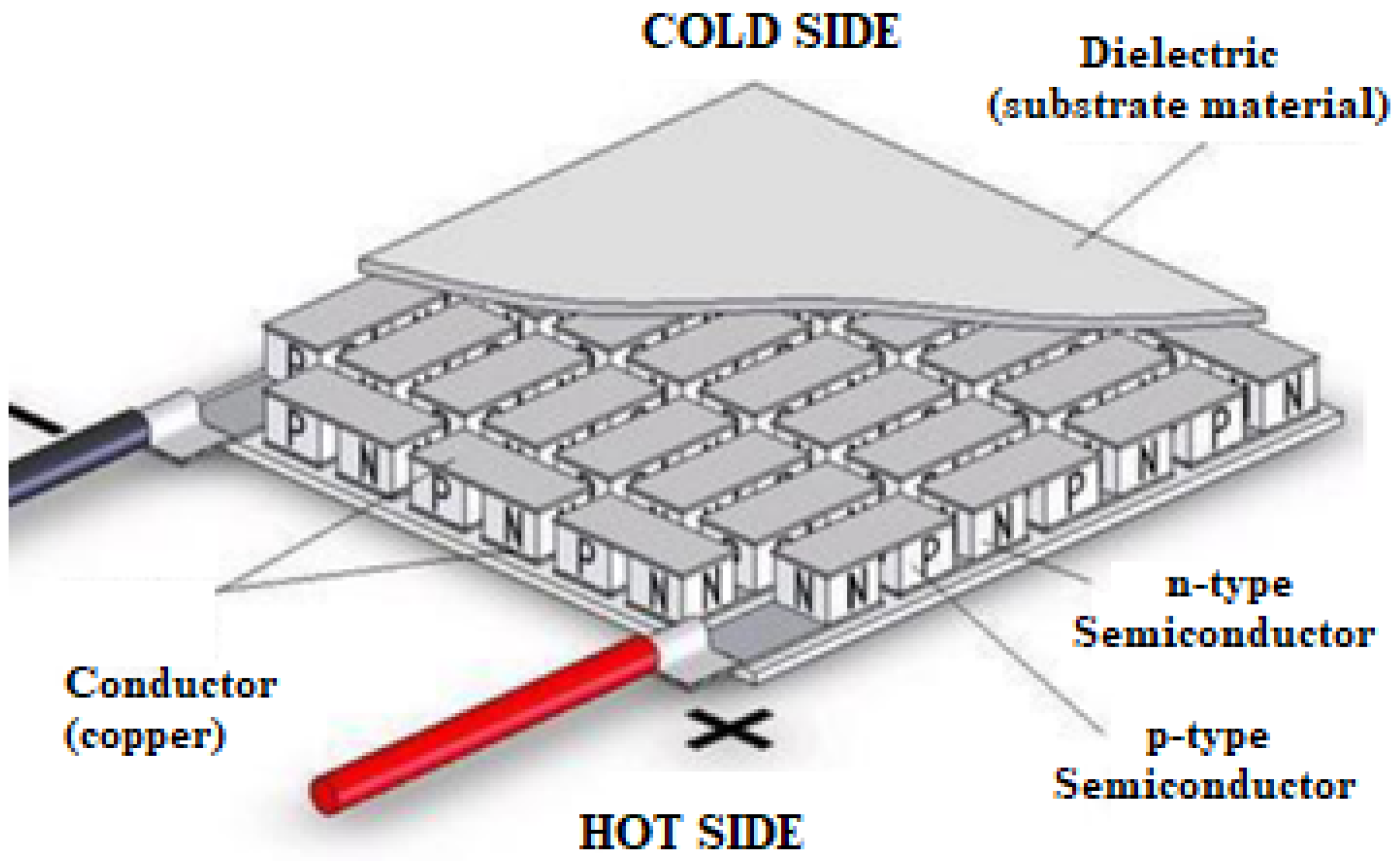
Thermoelectric generators are formed by combining p- and n- type semiconductor materials to convert thermal energy into electrical energy. In 1822, Seebeck noticed that a needle magnet deviated when different metals were bonded together and also underwent a temperature gradient [25]. Today, TEGs are produced according to this principle. TEGs are formed by combining p- and n-type semiconductors (electrically in series and thermally in parallel) between two different metal surfaces in the form of sandwiches. As shown in Figure 2, when a temperature difference occurs between the lower and upper surfaces of the metals, there is a flow of electrons from the anode to the cathode and a voltage is generated [17]. The amount of voltage generated is directly proportional to the temperature gradient between the surfaces.
The voltage produced by the thermoelectric generator can be expressed as a temperature gradient function, as follows:
where αp = Seebeck coefficients of the p-type semiconductor; αn = Seebeck coefficients of the n-type semiconductor; and ΔT = temperature gradient between hot surface and cold surface (TH–TC).
V = (αp − αn) ΔT
Figure 3 illustrates the electrical model of a typical TEG. If TEGs are assumed to be under a constant temperature gradient and the internal contact thermal resistance effect is negligible, they can be modelled as a series circuit with an equivalent internal resistance and a constant voltage source [26].
A thermoelectric energy harvesting system includes the following parts:
- Heat source: This must be an environmental source that produces heat naturally or artificially. Different sources produce differing levels of heat. Heat may be the goal of production or may be produced as a by-product of system operation.
- Thermoelectric generator: This converts heat from the heat source into electrical energy. A temperature difference is produced by keeping the cold surface cold while the hot surface is heated by the heat source. The cold surface can be prevented from heating up by means of natural or forced convection. Natural convection does not require energy but forced convection requires an additional energy source for devices such as fans.
- DC-to-DC converters: These are a critically important component of thermoelectric energy harvesting systems. Because TEGs have low levels of output voltage, the voltage often needs to be increased to make it useful. Increasing the DC voltage to another voltage level is accomplished using DC-to-DC converters or micro transformers. Transformers are formed by winding copper wire on a core as two separate groups. Depending on the number of windings, the voltage given from the input winding is taken at a higher level than the output winding.
- Battery: This is used to store DC voltage. A supercapacitor or rechargeable battery can be used to store amplified voltage from the DC-to-DC converter. Such batteries prevent energy losses caused by decreases in input voltage or the complete loss of voltage supply. Batteries can also store energy for later use during periods of excessive energy harvesting.
- Loads: These enable energy obtained from energy harvesting to be used. Microprocessors, sensors, or actuators can all be used as loads.
As stated above, the conversion of thermal energy into electrical energy is explained in terms of the Seebeck effect, and the devices used for this purpose are called thermoelectric generators [27,28]. In addition, the conversion of electrical energy into thermal energy is known as the Peltier effect, and the devices used for this purpose are called thermoelectric coolers (TECs) [29,30,31,32].
3. Experimental Study
3.1. Conceptual Design
As shown in Figure 4a, the prototype for harvesting thermoelectric energy consists of two TEGs (SP184827145SA), an aluminium heat sink, and thermal paste as a thermal pad. When heated by solar radiation, the PV panel transfers thermal energy to the hot surfaces of the TEGs through the thermal pad. The thermal paste on the right (cold) surfaces of the TEGs reduces the contact thermal resistance between the aluminium heat sink and the TEGs and allows the heat to pass. The aluminium heat sink dissipates the heat transferred over the TEG into still (non-windy) air by means of natural convection and ensures that the cold surface maintains a constant temperature over time. This maintains the temperature gradient between the hot and cold surfaces of the TEGs and results in generation of an output voltage. Figure 4b provides a block diagram of the system. The supercapacitor and battery were charged by increasing the obtained output voltage.
The temperatures of PVs can exceed 60 °C depending on climatic conditions. In this study, any excess heat was transferred to the TEGs and the heat sink was used to dissipate the heat transferred to the cold surface. The aluminium heat sink required no fans and, hence, no additional sources of energy. Cooling was passively achieved. However, temperatures cannot be lowered to any great degree using passive cooling. This results in low temperature gradients and low levels of harvested energy. To alleviate this, two TEGs with dimensions of 40 mm × 40 mm × 3.3 mm were used. The physical dimensions of the aluminium heat sink also affect energy harvesting in the prototype. According to the laws of thermodynamics, any increase in heat-emitting surface areas will increase the amount of heat transferred. Increasing the length and number of heat sink fins increases their surface area and will increase the amount of energy harvested as the temperature gradient is increased. The physical dimensions of the aluminium heat sink used in the prototype are given in Figure 5.
3.2. Energy Harvesting Interface Circuit
TEGs are devices that produce low output voltages as a result of the low temperature gradients to which they are exposed. For this reason, thermoelectric energy harvesting is a challenging task. In this study, passive cooling and heat transfer in stagnant air resulted in low levels of harvested energy. For this reason, an integrated DC-to-DC converter, LTC 3108-01, was used to make the low output voltage of TEGs useful. This interface circuit (IC) was chosen because it has an input voltage-boosting topology as low as 20 mV. In addition, its 2.2 V LDO output was sufficient to power an external microprocessor.
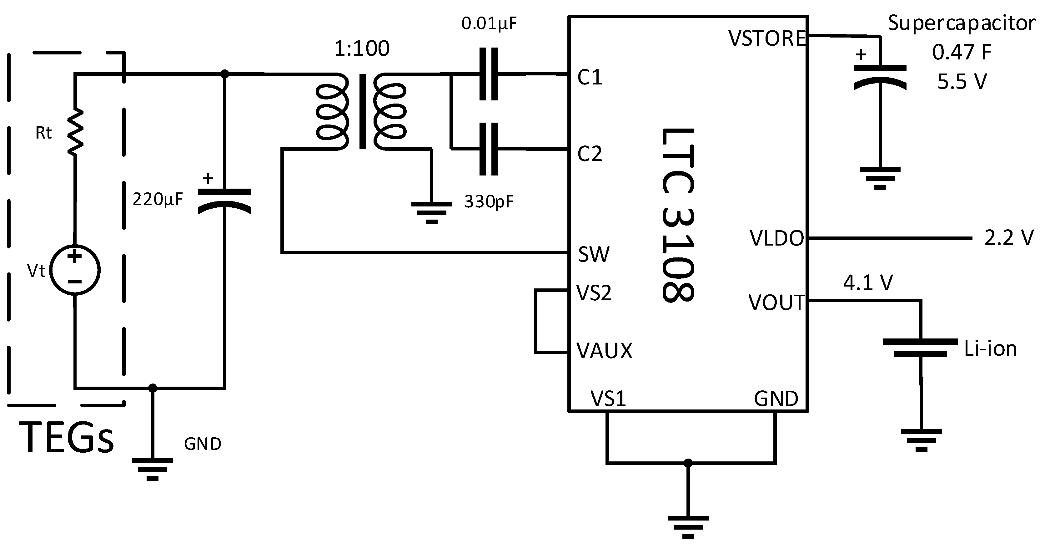
Figure 6 is a schematic representation of the circuit used in this study. Low-voltage energy from the TEGs is increased by a micro transformer at a ratio of 1:100 and it enters the charge pump and rectifier circuit through the C1 capacitor. The AC voltage generated in the secondary winding of the transformer is boosted and rectified using an external capacitor and enters the N-Channel Gate Drive Circuit via the C2 capacitor. A MOSFET switch is used as a resonant step-up oscillator. The oscillation frequency is typically in the range of 10 kHz to 100 kHz and is determined by the inductance of the transformer’s secondary winding. In the circuit shown in Figure 6, the rectifier current feeds the VAUX pin. When the VAUX reaches 2.5 V, the IC allows the VOUT to start charging. VOUT is then charged, and the output voltage is adjusted to 4.1 V to charge the single-cell li–ion battery by programming the VS1 and VS2 pins (VS1 = GND, VS2 = VAUX). When the output voltage drops below the set value, the charging current remains active until the VOUT rises above 2.5 V. When the VOUT reaches the desired value, the charging current is turned off. When VOUT reaches 4.1 V, the VSTORE pin is charged up to VAUX voltage levels. The 0.47 F 5.5 V supercapacitor connected to the VSTORE was previously charged and was used to power the system if input voltage were lost or could not provide the current demanded by the outputs. While the system was operating, the harvested energy was stored in a single-cell rechargeable li–ion battery connected to VOUT.
3.3. Experimental Set-Up
Experimental studies were carried out in Aksaray, Turkey, in April. Table 2 presents the geographical and solar parameters of the study location. These parameters affect variables, such as the angle of incidence of the sun’s rays, which fall on the PV panel and cause its front and rear surfaces to heat up. The experiments were carried out in a windless environment (stagnant air). At first, the panel was covered, and the experiment was begun by reducing the panel temperature to an ambient temperature. The experiment was originally intended to be carried out using one TEG, but because very low power output was obtained, it was decided to use two TEGs in series. As shown in Figure 7, the experimental setup was designed to measure the harvested voltage, the output voltage, the current and power of the DC-to-DC converter, and the temperature gradient between the surfaces of the TEGs. The experimental procedures were carried out on a real PV panel to obtain real temperature differences. DC-to-DC converter input and output values were measured and recorded with multimeters. Table 3 provides the details of models and technical specifications of all the devices used for experimental and measurement purposes.
4. Results and Discussion
The panel was uncovered and exposed to direct sunlight and measurement recordings were started. The panel and heat sink temperatures were measured with a thermal camera. Figure 8 shows a thermal image of the panel and the TEG prototype. Experimental findings showed that temperature of the PV exposed to direct solar radiation could exceed 60 °C. The heat sink reduced the temperature coming from the PV panel over the TEG by up to 45 °C. As shown in Figure 9a, while the temperature of the PV panel increased with exposure to sunlight over time, the temperature gradient also increased until temperature stability was attained. At this point, the PV panel temperature was recorded as 64.88 °C, the heat sink temperature was 43.8 °C, and the usable temperature gradient attained a maximum of 21.08 °C.
The output voltages of TEGs increased as the PV panel heated up. In Figure 9b, the input voltage (output voltage of TEGs) and the output current of the DC-to-DC converter are shown. By connecting TEGs in series, a maximum voltage of 120 mV was harvested. The input voltage of the DC-to-DC converter rose to 4.1 V open-circuit voltage, as shown in Figure 9d. An output voltage of 4.1 V was chosen because the li–ion battery can be safely charged when the full voltage level is around 4.1 V. Charging was achieved by connecting an empty battery with a voltage of 3.1 V to the system. The charging current of the battery (output current of the DC-to-DC converter) rose to a maximum of 147 µA, as shown in Figure 9b. The maximum harvested energy produced by the system was 458.64 mW, as shown in Figure 9c. It was observed that the amount of harvested energy declined to around 350 mW over time, mainly because heat generated on the back surface of the PV affects both the heat sink and the exposed lateral surfaces of the TEG. Air in contact with the back surface of the heated PV also warms up and rises. The rising air hits the heat sink where it can move, causing a slight increase in temperature between the PV surface and the heat sink, where it cannot rise and discharge. This disrupts the thermal stability of the system and can thus be considered as a disruptive factor in the system.
To date, there has been no systematic review of research into thermoelectric energy harvesting from photovoltaic panels. For this reason, it may be worthwhile to compare the results of this study with other studies of thermoelectric energy harvesting studies reported in the literature. The authors of [21] found that waste heat from train tracks heated with solar energy could be converted into electricity with the thermoelectric energy harvesting method. As in this study, passive cooling was used, energy was stored, and a power output of 316.8 mW was obtained, a value close to the figure reported in this article, although current and voltage values of the energy obtained were different. However, these values could be brought into line by means of electronic converters. The similar results can be best explained by the passive cooling and the close temperature gradients of the two studies.
Figure 9.
(a) PV, heat sink temperature and temperature gradient; (b) output current and input voltage; (c) harvested power (output power); and (d) battery and output voltage.
Figure 9.
(a) PV, heat sink temperature and temperature gradient; (b) output current and input voltage; (c) harvested power (output power); and (d) battery and output voltage.

The system proposed here ensures that the power required for PV monitoring systems is made available through the thermoelectric energy harvesting method. During this study, it was observed that the system harvested a remarkable amount of energy at specified temperature gradients. It should be noted that the experiments were carried out on a sunny day, but the system does have the capacity to harvest energy at lower temperature gradients when the sun’s rays do not fall directly on the PV. However, the energy harvested by the system is completely dependent on weather conditions and heat sink dimensions. The amount of energy harvested varies according to the wind speed, climate type, and the temperature of the environment where the PVs are located. If the temperature gradient is high in optimum weather conditions, the system will likely achieve a considerable reduction in battery maintenance costs and offer a less costly alternative energy solution by reducing the battery maintenance costs of PV monitoring systems. In addition, a fully developed thermoelectric energy harvesting system might contribute to the production of more affordable technology, such as thermal cameras and PV monitoring systems. Systems in which the temperatures of PVs can be continuously monitored with multiple temperature sensors could be developed and energy needs better met using the kind of thermoelectric energy harvesting systems developed in this study.
5. Conclusions
This paper describes a study of a prototype means of thermoelectric energy harvesting which uses thermal energy from heat on photovoltaic panels. The harvested energy can be used as a renewable energy source to power sustainable PV monitoring systems. Additionally, it could lead to the development of new low-cost PV monitoring systems. Study conclusions can be stated as follows:
- It was observed that the temperature gradient between the PV panel and the heat sink at Aksaray in April rose to a maximum of 21.08 °C. It should be noted that the temperature gradient depends on the heat sink dimensions.
- In experimental studies, the thermoelectric energy harvesting prototype produced a current of 147 µA at the maximum temperature gradient. The maximum power obtained was 458.64 mW. Continuous and constant power peaked at around 350 mW. Although the harvested power is not enough to run a system, the battery can be charged and used as a source of any system. In this case, battery replacement costs can be reduced by extending the life of the battery.
- More energy could be harvested by increasing the number of TEGs used in the thermoelectric energy harvesting prototype. However, the amounts of energy harvested will always be affected by climate and weather conditions and by changes in temperature distributions.
- By adjusting the output voltage of the LTC 3108 chip to 4.1 V, the safe charging voltage of the 1 s lipo (Maximum full voltage is 4.1 V) battery was provided. When the battery is fully charged, charging will not continue. Therefore, since the charging voltage cannot exceed 4.1 V, battery safety will be ensured. If the energy harvesting continues in case the battery is fully charged, the energy obtained will be wasted. In order to prevent this situation, TEG number and battery capacity can be optimized by evaluating the power consumption of the monitoring system, the amount of energy harvested and the battery capacity (mAh).
- The total cost of the thermoelectric energy harvesting system (including cables and electronic components) was USD 23.196. In order to determine the investment recovery of the system, it is necessary to compare the gains of the system with the geographical conditions of the region where the solar plant is located, the type and quality of the panel used, the number and type of failures in a certain period (annually or monthly, etc.), and the energy losses caused by these failures.
- Studies reported in the literature have aimed at removing the waste heat from photovoltaic panels, because it reduces the efficiency of the panels. In this study, for the first time, waste heat from the panels was not removed from the system but converted into useful electrical energy. This may inspire many comparable future studies on the removal of heat and making it useful.
- The use of harvested energy in PV monitoring systems can reduce battery maintenance costs or provide a short-term energy solution in the absence of supply. The renewable energy source presented here may lead to the development of new, low-cost PV monitoring systems which cannot yet be tested due to lack of energy.
- In future studies, a panel monitoring system can be developed and integrated into the energy harvesting system. A monitoring system can be designed that can monitor the temperature of certain points on the panel in real time and set off an alarm according to the determined limit temperatures.
Funding
This research received no external funding.
Institutional Review Board Statement
Not applicable.
Informed Consent Statement
Not applicable.
Data Availability Statement
Data are contained within the article.
Conflicts of Interest
The authors declare no conflict of interest.
References
- KhareSaxena, A.; Saxena, S.; Sudhakar, K. Solar energy policy of India: An overview. CSEE J. Power Energy Syst. 2020, 8, 1–32. [Google Scholar] [CrossRef]
- Solangi, K.H.; Islam, M.R.; Saidur, R.; Rahim, N.A.; Fayaz, H. A review on global solar energy policy. Renew. Sustain. Energy Rev. 2011, 15, 2149–2163. [Google Scholar] [CrossRef]
- Coşgun, A.E.; Demir, H. The experimental study of dust effect on solar panel efficiency. J. Polytech. 2021, 1–8. [Google Scholar] [CrossRef]
- Demir, H. Frequent faults on the DC side in photovoltaic systems. In Theory and Research in Engineering; Gece Publishing: Ankara, Turkey, 2020; pp. 353–367. ISBN 978-625-7243-79-7. [Google Scholar]
- Hiyama, T.; Kitabayashi, K. Neural network based estimation of maximum power generation from PV module using environmental information. IEEE Trans. Energy Convers. 1997, 12, 241–247. [Google Scholar] [CrossRef]
- Demir, H.; Coşgun, A.E. Performance prediction approach using rainfall based on artificial neural network for PV module. In Proceedings of the International Symposium on Current Developments in Science, Technology and Social Sciences, Gaziantep, Turkey, 12–13 April 2021; pp. 94–98. [Google Scholar]
- Triki-Lahiani, A.; Abdelghani, A.B.-B.; Slama-Belkhodja, I. Fault detection and monitoring systems for photovoltaic installations: A review. Renew. Sustain. Energy Rev. 2018, 82, 2680–2692. [Google Scholar] [CrossRef]
- Heidari, N.; Gwamuri, J.; Townsend, T.; Pearce, J.M. Impact of snow and ground interference on photovoltaic electric system performance. IEEE J. Photovolt. 2015, 5, 1680–1685. [Google Scholar] [CrossRef] [Green Version]
- Madeti, S.R.; Singh, S. A comprehensive study on different types of faults and detection techniques for solar photovoltaic system. Sol. Energy 2017, 158, 161–185. [Google Scholar] [CrossRef]
- Nezami, S.; Jung, H.J.; Lee, S. Design of a disk-swing driven piezoelectric energy harvester for slow rotary system application. Smart Mater. Struct. 2019, 28, 074001. [Google Scholar] [CrossRef]
- Enescu, D. Thermoelectric energy harvesting: Basic principles and applications. In Green Energy Advances; IntechOpen: London, UK, 2019. [Google Scholar]
- Adu-Manu, K.S.; Adam, N.; Tapparello, C.; Ayatollahi, H.; Heinzelman, W. Energy-harvesting wireless sensor networks (EH-WSNs): A review. ACM Trans. Sens. Netw. 2018, 14, 1–50. [Google Scholar] [CrossRef]
- Demir, H. Enerji hasatlama: Düşük ve yüksek güçte. In Mühendislik Alaninda Akademik Çalişmalar; Duvar Yayınları: Ankara, Turkey, 2021; ISBN 978-625-7502-57-3. [Google Scholar]
- Bierschenk, J.L. Thermoelectrics. In Energy Harvesting Technologies; Priya, S., Inman, D.J., Eds.; Springer: Boston, MA, USA, 2009; pp. 337–350. ISBN 9780387764634. [Google Scholar]
- Renge, S.; Barhaiya, Y.; Pant, S.; Sharma, S. A review on generation of electricity using Peltier module. Int. J. Eng. Res. 2017, 6, 453–457. [Google Scholar] [CrossRef]
- Nesarajah, M.; Frey, G. Multiphysics simulation in the development of thermoelectric energy harvesting systems. J. Electron. Mater. 2016, 45, 1408–1411. [Google Scholar] [CrossRef]
- Carmo, J.P.; Goncalves, L.M.; Correia, J.H. Thermoelectric microconverter for energy harvesting systems. IEEE Trans. Ind. Electron. 2010, 57, 861–867. [Google Scholar] [CrossRef] [Green Version]
- Abdal-Kadhim, A.M.; Leong, K.S. Application of thermal energy harvesting from low-level heat sources in powering up WSN node. In Proceedings of the 2nd International Conference on Frontiers of Sensors Technologies (ICFST), Shenzhen, China, 14–16 April 2017; pp. 131–135. [Google Scholar]
- Nesarajah, M.; Frey, G. Thermoelectric power generation: Peltier element versus thermoelectric generator. In Proceedings of the 42nd Annual Conference of the IEEE Industrial Electronics Society, Florence, Italy, 23–26 October 2016; pp. 4252–4257. [Google Scholar]
- Flores-Verdad, G.E.; Espinosa, G. A CMOS startup circuit for thermoelectric energy harvesting systems. IEEE Lat. Am. Trans. 2019, 17, 26–30. [Google Scholar] [CrossRef]
- Gao, M.; Su, C.; Cong, J.; Yang, F.; Wang, Y.; Wang, P. Harvesting thermoelectric energy from railway track. Energy 2019, 180, 315–329. [Google Scholar] [CrossRef]
- Çalhan, A.; Gündoğdu, K.; Cicioğlu, M.; Bayrakdar, M.E. Energy harvesting unit design for body area networks. Sak. Univ. J. Comput. Inf. Sci. 2019, 2, 1–8. [Google Scholar] [CrossRef]
- Chen, Z.; Xia, Y.; Shi, G.; Xia, H.; Wang, X.; Qian, L.; Ye, Y. Enhanced piezoelectric energy harvesting power with thermoelectric energy assistance. J. Intell. Mater. Syst. Struct. 2021, 32, 2260–2272. [Google Scholar] [CrossRef]
- Liu, Y.; Yin, L.; Zhang, W.; Wang, J.; Hou, S.; Wu, Z.; Zhang, Z.; Chen, C.; Li, X.; Ji, H.; et al. A wearable real-time power supply with a Mg3Bi2-based thermoelectric module. Cell Rep. Phys. Sci. 2021, 2, 100412. [Google Scholar] [CrossRef]
- Bell, L.E. Cooling, heating, generating power, and recovering waste heat with thermoelectric systems. Science 2008, 321, 1457–1461. [Google Scholar] [CrossRef] [Green Version]
- Siouane, S.; Jovanovic, S.; Poure, P. Equivalent electrical circuit of thermoelectric generators under constant heat flow. In Proceedings of the IEEE 16th International Conference on Environment and Electrical Engineering (EEEIC), Florence, Italy, 7–10 June 2016; pp. 1–6. [Google Scholar]
- Champier, D.; Bédécarrats, J.; Kousksou, T.; Rivaletto, M.; Strub, F.; Pignolet, P. Study of a TE (thermoelectric) generator incorporated in a multifunction wood stove. Energy 2011, 36, 1518–1526. [Google Scholar] [CrossRef] [Green Version]
- Champier, D.; Bédécarrats, J.; Rivaletto, M.; Strub, F. Thermoelectric power generation from biomass cook stoves. Energy 2010, 35, 935–942. [Google Scholar] [CrossRef]
- Simons, R.E.; Ellsworth, M.J.; Chu, R.C. An assessment of module cooling enhancement with thermoelectric coolers. J. Heat Transf. 2005, 127, 9. [Google Scholar] [CrossRef]
- Enescu, D. Thermoelectric refrigeration principles. In Bringing Thermoelectricity into Reality; Aranguren, P., Ed.; InTechOpen: London, UK, 2018; ISBN 978-1-78923-440-4. [Google Scholar]
- Cheng, T.-C.; Cheng, C.-H.; Huang, Z.-Z.; Liao, G.-C. Development of an energy-saving module via combination of solar cells and thermoelectric coolers for green building applications. Energy 2011, 36, 133–140. [Google Scholar] [CrossRef]
- Coşgun, A.E.; Demirel, H. On-off controller design for a portable refrigerator. In Proceedings of the International Conference Intelligent Technologies in Logistics and Mechatronics System (ITELMS’2015), Panevezys, Lithuania, 21–22 May 2015; pp. 80–82. [Google Scholar]
Figure 2.
Thermoelectric generator [15].
Figure 2.
Thermoelectric generator [15].

Figure 3.
The equivalent circuit of a typical thermoelectric generator, where VT—constant voltage source; RT—equivalent internal resistance; VOUT—output voltage.
Figure 3.
The equivalent circuit of a typical thermoelectric generator, where VT—constant voltage source; RT—equivalent internal resistance; VOUT—output voltage.

Figure 4.
(a) Schematic diagram and (b) block diagram of the thermoelectric-energy-harvesting prototype photovoltaic panel.
Figure 4.
(a) Schematic diagram and (b) block diagram of the thermoelectric-energy-harvesting prototype photovoltaic panel.

Figure 5.
Aluminium heat sink.

Figure 6.
Schematic of thermoelectric energy harvesting circuit.

Figure 7.
(a) TEG and aluminium heat sink placed behind the photovoltaic panel, (b) DC-to-DC convertor with li–ion rechargeable battery, and (c) test instrumentation including thermal camera, multimeters and personal computer.
Figure 7.
(a) TEG and aluminium heat sink placed behind the photovoltaic panel, (b) DC-to-DC convertor with li–ion rechargeable battery, and (c) test instrumentation including thermal camera, multimeters and personal computer.

Figure 8.
Thermal imaging of the photovoltaic panel with TEG prototype.

Table 2.
Geographical and solar parameters for Aksaray.
| Latitude (°) | Longitude (°) | Altitude(m) | Solar Radiation (kWh/m2) (April) | |
|---|---|---|---|---|
| Aksaray | 38.37 | 34.02 | 979 | 5.566 |
Table 3.
Models and technical specifications of all devices.
| Brand and Model | Range | Resolution | |
|---|---|---|---|
| Multimeter 1 | UNIT and UT61D+ | 1000 V (for DC voltage) 10 A (for DC current) | ±(0.8% + 5) (for DC voltage) ±(1.0% + 2) (for DC current) |
| Multimeter 2 | TT Technic and DT202 | 600 V (for DC voltage) | ±(1.0% + 3) (for DC voltage) |
| Multimeter 3 | TT Technic and MY62 | 1000 V (for DC voltage) 10 A (for DC current) | ±(0.8% + 1) (for DC voltage) ±(2.0% + 5) (for DC current) |
| Thermal camera | Optris and PI160 | Temperature: −20…+100 °C | 160 × 120 pixels |
Publisher’s Note: MDPI stays neutral with regard to jurisdictional claims in published maps and institutional affiliations. |
© 2022 by the author. Licensee MDPI, Basel, Switzerland. This article is an open access article distributed under the terms and conditions of the Creative Commons Attribution (CC BY) license (https://creativecommons.org/licenses/by/4.0/).
Share and Cite
MDPI and ACS Style
Demir, H. Application of Thermal Energy Harvesting from Photovoltaic Panels. Energies 2022, 15, 8211. https://doi.org/10.3390/en15218211
AMA Style
Demir H. Application of Thermal Energy Harvesting from Photovoltaic Panels. Energies. 2022; 15(21):8211. https://doi.org/10.3390/en15218211
Chicago/Turabian StyleDemir, Hasan. 2022. "Application of Thermal Energy Harvesting from Photovoltaic Panels" Energies 15, no. 21: 8211. https://doi.org/10.3390/en15218211
Note that from the first issue of 2016, this journal uses article numbers instead of page numbers. See further details here.