Article

Research on an Off-Chip Microvalve for Pneumatic Control in Microfluidic Chips

1
School of Mechanical and Electronic Engineering, Zhengzhou University of Light Industry, Zhengzhou 450002, China
2
Henan Xixi Highway Construction Co., Ltd., Nanyang 474450, China
3
Zhengzhou Dongchen Science & Technology Co., Ltd., Zhengzhou 450000, China
4
School of Highway, Henan College of Transportation, Zhengzhou 451450, China
5
Department of Fluidic Control and Automation, Harbin Institute of Technology, Harbin 150001, China
*
Author to whom correspondence should be addressed.
Energies 2022, 15(21), 8094; https://doi.org/10.3390/en15218094
Submission received: 15 September 2022 / Revised: 14 October 2022 / Accepted: 21 October 2022 / Published: 31 October 2022
(This article belongs to the Special Issue New Insights of Intelligent and Integrated Fluid Power Systems)

Abstract

:
A compact, rapid, and portable off-chip pneumatic control valve is significant for the miniaturization and integration of external pneumatic systems for microfluidic chips. In this work, an off-chip microvalve with a high-speed electromagnetic switch actuator and a polydimethylsiloxane (PDMS) material valve body has been designed to be easily encapsulated, simulated using MATLAB/Simulink software, and tested in a micromixer. Multi-physical coupling mathematical models are developed based on the elastic deformation force of the valve membrane, the driving force of the valve core, and the fluid force in the microchannel. Two single microvalves are used to form a three-way microvalve, which can control the air pressure in a pneumatic microchannel on the microfluidic chip. The relationship between the flow–duty cycle, the flow–pressure difference of the single electromagnetic microvalve, and the load pressure of the three-way microvalve is simulated and analyzed. Sample mixing performance controlled by the proposed off-chip three-way microvalve was tested to evaluate the pneumatic control capability, and the results show that the undertaking can fully satisfy the needs of a pneumatic microfluidic chip for most applications.

1. Introduction

A bulky external pneumatic control system has become the biggest obstacle to furthering highly integrated pneumatic microfluidic chips, which makes it challenging to achieve the ultimate goal of portable microfluidic chips. It is an inevitable trend of microfluidic technology to miniaturize, modularize, and integrate the external support components and detection systems of microfluidic chips [1,2,3]. The core functional components of pneumatic microfluidic chips, such as microvalves, micromixers, and micropumps, play a crucial role in liquid reagents on the chip [4,5,6]. Therefore, the external pressure control system of a pneumatic microfluidic chip determines whether the introduction, sample change, pretreatment, analysis, and detection of sample reagents on the chip can be implemented quickly and stably. To meet the needs of the external pressure control system of the pneumatic microfluidic chip and realize the modularity of the valve group for the overall integration with the microfluidic chip, multiple performance indicators of the three-way microvalve, including volume, working pressure, flow rate, and response speed, should be comprehensively considered. The main requirements are as follows:
In terms of apparent size, the length, width, and height of electromagnetic microvalve after encapsulation are less than the width size of the microfluidic chip, so it is easy to integrate with a microfluidic chip. Microfluidic chips are typically 1 inch (25 mm) wide and no longer than 3 inches (76 mm) long. For example, the chip geometry is 25 mm × 30 mm for parallel DNA recovery, 25 mm × 35 mm for chemical synthesis hydrolysis reaction, and 25 mm × 40 mm for flow cytometry. The geometric size of the disposable integrated diagnostic card chip for public healthcare is 25 mm × 75 mm [7,8]. The length, width, and height of the off-chip electromagnetic microvalve should be less than the width (25 mm) of the ordinary microfluidic chip after encapsulation so that it can be integrated with the microfluidic chip as an external control module.
The encapsulation process is simple and reliable, and the price is low. PDMS equipment is generally manufactured by a complex mold method, so the preparation of a micro-structure mold is the key to the encapsulation process of the valve body of the off-chip microvalve [9,10,11,12]. In this study, based on the analysis of the existing fabrication process of micro-structure die, a simple, low-cost, and high-sealing-strength electromagnetic microvalve encapsulation method is proposed.
The PDMS pressure-driven microvalves shall be able to withstand 200 kPa pressure. The liquid microchannel size of a membrane valve on a pneumatic microfluidic chip is generally in dozens of microns, and the required driving pressure is generally in dozens of kilopascals. When the PDMS-actuated membrane is thicker (greater than 50 μm), it requires an actuated pressure of 120 kPa. Lee et al. completed an organic synthesis of fluoro-radiolabeled molecular and 2-deoxy-2-[18F] fluorO-D-glucose using a pneumatic microfluidic chip integrated with a push-up diaphragm valve. The liquid layer arc channel was 56 μm, the PDMS-actuated membrane thickness was 10 μm, and the driving pressure was 24 kPa [13]. The cell culture chip developed by Wu et al. was used to pump the suspension of hMSCs and McF-7 with a pneumatic peristaltic micropump, in which the liquid layer arc channel was 100 μm, the PDMS-actuated membrane thickness was 100 μm, the driving pressure was 118 kPa [14]. Therefore, for the aerodynamic microfluidic chip currently studied, the actuated membrane thickness of PDMS is 10–100 μm, the depth of a curved liquid channel is less than 100 μm, and the driving pressure range is generally 100–120 kPa, rarely exceeding 150 kPa [15]. To keep the design allowance, the maximum working pressure of the PDMS pneumatic microvalve is 200 kPa.
The maximum working frequency of the off-chip microvalve is 100 Hz, which can be used as a high-speed on–off valve. Because of the long response time and low reversing frequency, the general on–off valve cannot meet the high precision control requirements of a pneumatic microfluidic system. For the pneumatic microfluidic chip, the response characteristics of the off-chip microvalve directly affect the dynamic performance of the on-chip pneumatic functional components. The response time of the high-speed on–off valve is generally less than 10 ms, its control mode is mainly pulse width modulation (PWM), and the performance of a PWM control system depends on the opening and closing speed of a high-speed switch microvalve [16,17]. Therefore, the sum of the full opening and closing time of the off-chip three-way microvalve proposed in this study should be less than 10 ms to meet the response speed requirements of a high-speed switching valve. The upper limit of on-chip response time should be 100 ms, which can meet the needs of most applications of pneumatic microfluidic chips [18,19,20]. The on-chip pneumatic components should also have a response time of less than 100 ms when used as a micromixer actuator because the upper limit vibration frequency is 10 Hz in most micromixing applications.
It is necessary to study the miniaturization and integration of the off-chip pneumatic control microvalve for pneumatic microfluidic chips. In order to avoid the use of external conventional-size servo valves, researchers studied the external pressure control valve. Sia et al. proposed a screw-driven pneumatic microvalve whose structure is filled with water in the control layer; screws are installed at the entrance of the control layer, and a PMMA plate is used as support. During screwing in, the pressure of the control layer increases, the valve film moves up, and the pneumatic microvalve closes. As the screw is unscrewed, the pressure of the control layer is reduced, the valve film recovers its deformation by its own elasticity, and the pneumatic microvalve is opened [21]. The drawback of this kind of pneumatic microvalve is that realizing automation is difficult, and it cannot be used repeatedly. Chia et al. proposed a PDMS thermal microvalve, which used a heating electrode as the driving component [22]. This method simplifies the control circuit and external support equipment but has the disadvantage of producing higher temperatures and easily destroying the activity of biological reagents. Takayama et al. proposed an off-chip pneumatic control microvalve that used inkjet printer needles as actuators [23]. The disadvantage of this method is that the position of the printer needle is fixed and the position of the microvalve is not flexible, which is unfavorable to the design of the microfluidic chip. Anjewierden et al. designed an electrostatic microvalve to replace the conventional-size servo valve in the external air passage [24]. Compared with the pneumatic microfluidic chip itself, the volume of the valve body is still large. The total length of the encapsulated microvalve including the PMMA bracket is 75 mm, and the driving voltage is as high as DC680V, which is far from meeting the requirements of portability and low power consumption for the pneumatic microfluidic chip system. Furthermore, the studies on dynamic response and flow rate characteristics of a membrane microvalve controlled by an off-chip solenoid array are still not perfect.
To replace the conventional-size servo valve, reduce the size of external devices, and improve the accuracy of on-chip membrane microvalves, a PDMS three-way electromagnetic microvalve is proposed in this study for off-chip pneumatic control of microfluidic devices. The PDMS three-way microvalve is constituted of two single electromagnetic microvalves. The single electromagnetic microvalve adopts a high-speed electromagnetic drive mode and PDMS body material, which facilitates integration with pneumatic microfluidic chips. The dynamic coupling mathematical model of the electromagnetic microvalve is established based on the elastic deformation force of the valve membrane, the driving force of the spool, and the fluid force in the microchannel. The dynamic characteristics of the three-way microvalve, including the open/close time, the flow rate of the valve port, and the average flow rate with different duty cycles and differential pressures, are studied by simulation and experiments. The mixing performance controlled by the proposed PDMS three-way electromagnetic microvalve is tested and analyzed to evaluate the pneumatic control performance of the proposed PDMS three-way microvalve. The effect of vibration frequency on mixing efficiency is studied to develop the relationship between mixing degree and driving frequency. The results indicate that the feasibility and effectiveness of this novel microvalve are satisfactory. The proposed PDMS three-way microvalve not only allows avoiding the use of large-volume and high-cost conventional-size servo valves or proportional valves that are difficult to integrate with pneumatic microfluidic chips but also can ensure the successful completion of biochemical analysis applications in the valve control task.

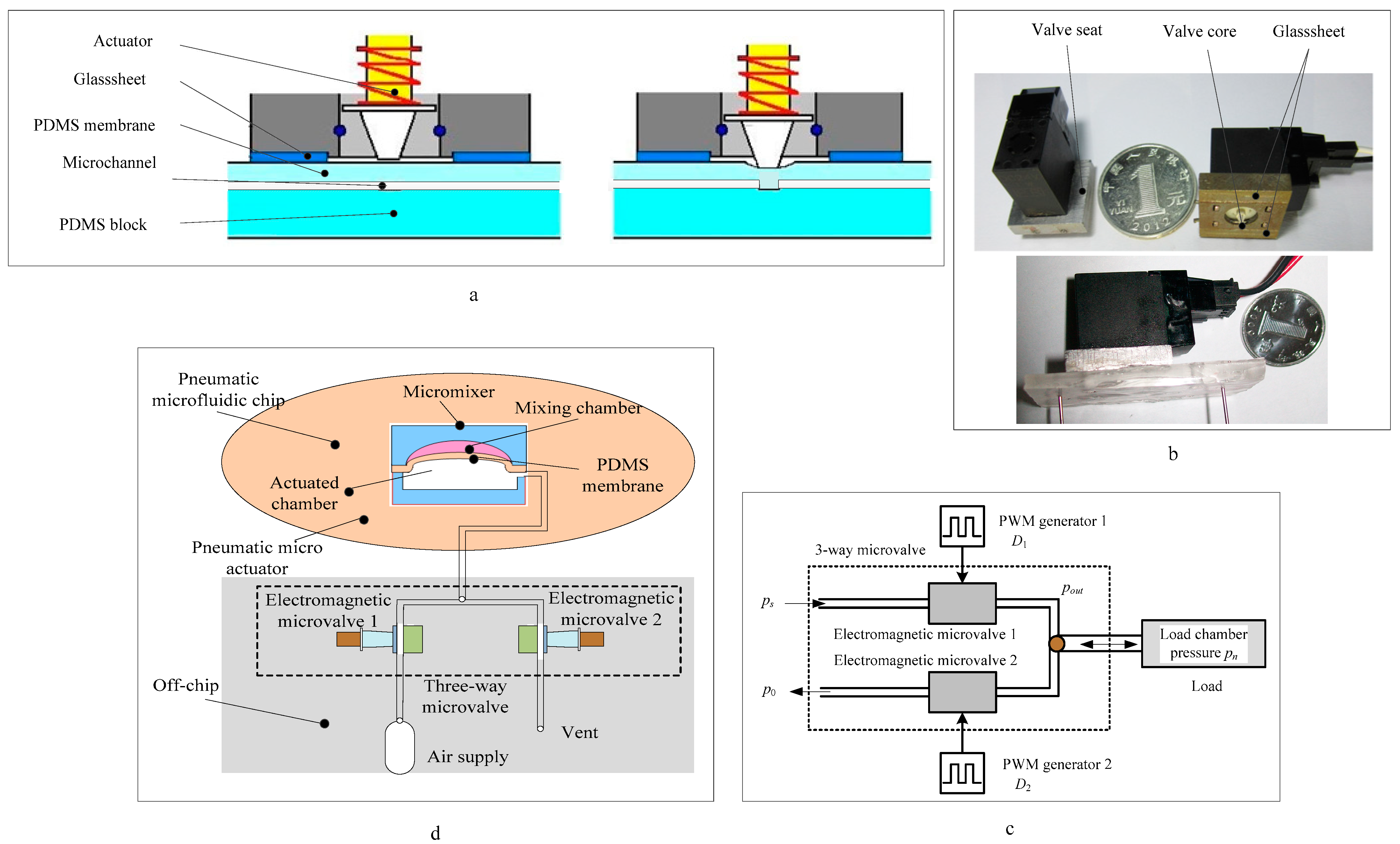
2. Architecture and Working Principle

The off-chip electromagnetic microvalve comprises an upper PDMS valve membrane, a lower PDMS thick block with a microchannel, and an electromagnetic actuator, as shown in Figure 1a. The working principle of electromagnetically actuated microvalve is as follows: When the electromagnetic actuator is not energized, the pretightening force of the spring pushes the valve core, which presses the upper PDMS valve membrane, and the valve-membrane deformation moves downward, blocking the valve port, and the microvalve is in the closed state. When the electromagnetic actuator is energized, the electromagnetic suction overcomes the elastic spring force and pulls up the valve core. The valve-membrane deformation is restored, and the microvalve is in the open state. When the electromagnetic actuator is powered off, the electromagnetic suction disappears, and the valve core moves downward under the action of the spring force, forcing the valve membrane to deform downward. The microchannel closes, and the microvalve is in the closed state again.
When the armature is energized, the magnetic pressure drop in the air gap between the armature and the electromagnetic core dominates the entire magnetic path. The electromagnetic actuator adopts DC24V voltage, 42 mA current, and 1W power consumption. The picture of the encapsulated electromagnetic actuator and microvalve is shown in Figure 1b. The head diameter of the armature is 10mm conical spool, and the end diameter (valve core) is 1 mm. The maximum displacement of the electromagnetic valve spool is 120 µm, and the depth of the microchannel on the valve body is 100 µm. Because the electromagnetic microvalve body is made of PDMS material, it has the characteristics of high elasticity and easy deformation. After the microvalve spool is completely closed, it will continue to move about 20 µm toward the PDMS substrate of the valve body, so the electromagnetic microvalve has the characteristics of positive cover. In order to facilitate the connection with the external supply gas path when testing the performance of the electromagnetic microvalve, the length, width, and height of the design dimensions are 20 mm, 500 µm, and 100 µm, respectively. The dimensions of the packaged microvalve are shown in Table 1. Detailed information about the fabrication process of the off-chip electromagnetic microvalve can be found in our previous study [25]. The off-chip three-way electromagnetic microvalve can be manufactured repeatedly using the preparation method recommended.
The working condition of the three-way microvalve is shown in Figure 1c. Two PWM excitation pulse signals simultaneously control the off-chip microvalve 1 and the off-chip microvalve 2 and further control the inlet and outlet of the load-actuated chamber, realizing the fine adjustment of the air pressure of the load-actuated chamber. It is noticed that the load-actuated chamber pressure pn is always less than or equal to the air source pressure ps. The load-actuated chamber is the actuated part of on-chip pneumatic components, such as microvalve, micropump, micromixer, and microreactor.
As shown in Figure 1d, the switch-type three-way microvalve is located outside the pneumatic microfluidic chip. The micromixer is on the pneumatic microfluidic chip, composed of a pneumatic microactuator and an upper mixing chamber. The proposed three-way microvalve is used to control the air pressure of the actuated microactuator in the mixer. When mixing behavior is required, the air pressure in the actuated chamber is controlled by the three-way microvalve. The PDMS membrane keeps moving up and down continuously with the air pressure of the actuated chamber. This can generate a vortex-type flow inside the mixing chamber. The pneumatic microactuator runs multiple cycles, and varieties of reagents in the mixing chamber are rapidly and thoroughly mixed due to convection caused by vibration. The pneumatic microactuator can be not only the actuated element of the on-chip micromixer but also the actuated element of the on-chip microvalve and micropump.
The proposed three-way microvalve has the following advantages over conventional solenoid valves: (1) small size; (2) compared with the conventional size of solenoid valves with metal, polyimide, polycarbonate, and other hard materials, a new type of valve body material, highly elastic PDMST, is adopted, which is easy to integrate with the pneumatic microfluidic chip; (3) the soft lithography encapsulation method is adopted, and this encapsulation process is simple, reliable, and low-cost, while the conventional-size solenoid valve adopts the traditional manufacturing method; (4) the PDMS valve membrane of the off-chip three-way microvalve also acts as a elastic spacer and has good sealing performance; (5) the valve core is located outside the valve chamber, not in direct contact with the working medium, which eliminates the hydraulic clamping force on the valve core, reduces noise and wear, and prolongs service life; (6) the structural design of the off-chip microvalve reduces the influence of hydraulic force, improving its working stability.

3. Numerical Simulation of the Off-Chip Microvalve

The working medium of the electromagnetic microvalve in this study is nitrogen (N2). Due to the small characteristic size, slow velocity, and small Reynolds number of the microchannel, the working fluid in the microchannel is in a laminar flow state. The compressibility effect of N2 is usually low at low flow rates, and its compressibility effect is negligible.
The dynamic mathematical model of the off-chip electromagnetic microvalve includes the electromagnetic actuator, the force–deformation mathematical model of the PDMS valve membrane, and the flow of the electromagnetic microvalve. The simulation model of the dynamic characteristics of the electromagnetic actuator and the microvalve is developed using MATLAB/Simulink software. The mathematical models of the electromagnetic actuator include self-induction coefficient, coil current, spool motion voltage, mechanical motion, and electromagnetic suction. The simulation model can be used to calculate the dynamic characteristics of the electromagnetic actuator, such as coil current, motion reverse electromotive force, electromagnetic suction, inductance, spool movement displacement, velocity, and acceleration. The mathematical models of the off-chip electromagnetic microvalve are not described as space is limited, and more detailed information can be found in our previous study [26].

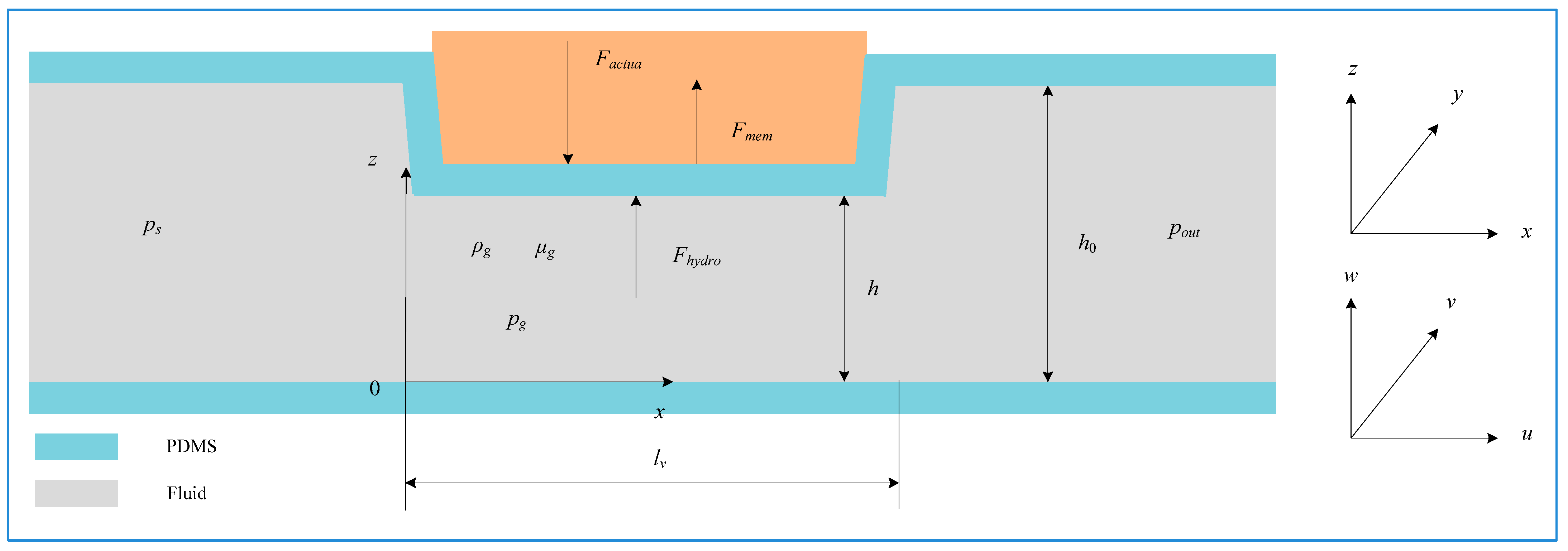
3.1. Model of the Valve-Membrane Force

In the working process of the three-way microvalve, the valve membrane is mainly affected by the driving force Factua of the valve core, the fluid energy Fhydro in the valve chamber, and the elastic force Fmem of the valve membrane itself, as shown in Figure 2. The valve membrane moves reciprocally along the Z-axis to open and close the off-chip microvalve. The depth of the fluid in the valve chamber changes with the motion of the valve membrane.
The length and width of the valve membrane are several millimeters. The thickness is several hundred microns, far less than the length and width, so the valve membrane can be simplified as a thin flexible plate; the motion of the valve membrane is regarded as the thin elastic plate in a variety of forces under the action of the combined power, along the Z-axis for the overall reciprocating motion. When the deformation of the valve membrane is within the range of elastic variation, the flexible plate stiffness k2 can be approximately constant. The off-chip microvalve is normally closed, and the displacement of the valve core is along the Z-axis direction. The inlet pressure of the off-chip microvalve is ps, and the outlet pressure is pout.
The length, width, and depth of the valve chamber are 1 mm, 500 μm, and 100 μm, respectively. The valve opening can be obtained by changing the fluid depth in the valve chamber in the range of 0~100 μm along the Z-axis. The size of the off-chip microvalve in this study is several hundred microns, and the fluid continuity equation and Navier–Stokes equation of macro fluid mechanics are still applicable [27,28].
Pressure and viscous force play a leading role in fluid flow in the valve chamber of the off-chip microvalve, which is similar to the theory of fluid film lubrication. Reynolds equation theory is used to simplify the fluid motion equation in the valve chamber. This process is constrained by the following conditions: (1) The fluid conforms to Newton’s law of viscosity. (2) The fluid movement is laminar flow. (3) The volume force on the fluid is ignored. (4) The inertia force on the fluid is ignored. (5) The height of the fluid in the valve chamber is minimal compared with the length of the valve membrane and the lower flow channel. It can be considered that the pressure and viscosity of the fluid in the valve chamber along the height direction remain unchanged. (6) The inner wall of the valve cavity is fixed, and there is no slip at the boundary. (7) The contact surface between the fluid in the valve chamber and the valve membrane is a plane.

3.2. Air–Solid Coupling Mathematical Model of the Valve Membrane

The fluid dynamics Fhydro subjected to the valve membrane can be calculated as follows [29]:
F h y d r o = A v p g d x d z = μ g A v l v 2 δ 3 δ ˙ + 1 2 ( p s + p o u t ) A v
The relation between the deformation and the force of the valve membrane can be calculated according to the mechanical motion model and Hooke’s law. The force of the valve membrane can be expressed as follows:
k 2 ( h 0 δ ) = F a c t u a F h y d r o
According to the motion mechanism of the valve core, the driving force Factua of the valve core can be obtained as follows:
F a c t u a = k 1 ( δ + δ 0 ) ( C v + C f ) d δ d t
According to Equations (1)–(3), the dynamic coupling mathematical model of the off-chip microvalve can be given as follows:
k 2 ( h 0 δ ) = F a c t u a + μ g A v l v 2 δ 3 δ ˙ 1 2 ( p s + p o u t ) A v
It can be seen from the above mathematical model that the elastic deformation force of the valve membrane, the driving force of the valve core, and the fluid force in the microchannel jointly determine the force of the valve membrane. It is theoretically verified that the PDMS three-way microvalve meets the performance design indexes such as response time and flow rate.
When the average Mach number M at the microscale is about 0.15, the influence of compressibility needs to be considered. According to the pressure differential and flow characteristics of the off-chip microvalve, when the valve port pressure difference is 200 kPa, the valve port flow rate can reach the highest, 126 m/s, M = 0.37. The flow velocity of the axis along the radial direction is suppressed by the air compressibility. The velocity change in the central regions of the groove is smooth, and the velocity gradient increases near the wall; as a result, the axial velocity gradient and axial pressure gradient are not constant [30]. Therefore, the valve port flow equation needs to consider the influence of the compressibility of air on the flow velocity in the microchannel. The airflow process at the valve port of the off-chip microvalve is approximately regarded as the one-dimensional isentropic flow of the ideal air in the contraction nozzle. The mass flow rate Q of the air is obtained based on the Sanville formula [31].
The thermal process of air throttling is simplified as an adiabatic process. The working medium N2 is a diatomic air, and the adiabatic index k is 1.41. For the different types of restrictor structures, the valve port flow coefficient kv1 = 0.6~0.8 [32], and kv1 = 0.68 is taken in this study. For air throttling on a microscale, the geometric dimensions of the flow passages before and after the throttle are still in the range of the microscale. The actual airflow process is far more complex than that for a nozzle of conventional size. Some studies point out that this formula is inconsistent with the actual flow rate and needs to be corrected [33,34]. When the depth-to-width ratio of the microchannel is less than or equal to 0.2, the air resistance increases significantly in front and back of the throttle port and at the throttle port, while the flow through the throttle port decreases. Therefore, kx1 is used for correction. kx1 is found to be 0.15 in this study. The mass flow rate of gas through the valve port can be obtained by the following equation:
Q = k v 1 k x 1 A p 2 K K 1 · p s R T s · φ ( ε )
where ε* is the critical pressure ratio upstream and downstream of the valve port, and ε* is 0.528. When ε is less than or equal to ε*, the air flows at the speed of sound, the flow rate of the electromagnetic valve port reaches the maximum, the decrease in the downstream pressure will not make the mass flow rate increase again, and there is the phenomenon of “choking”. When ε is greater than ε*, air flows at subsonic speed, and the mass flow rate of the valve port is related not only to the effective flow area but also to the upstream and downstream pressure of the valve port. The nitrogen flow function can be calculated as follows:
φ ( ε ) = { ( K 1 ) 2 ( 2 K + 1 ) ( K + 1 ) / ( K 1 ) ε ε * ε 2 / K ε ( K + 1 ) / K ε > ε *

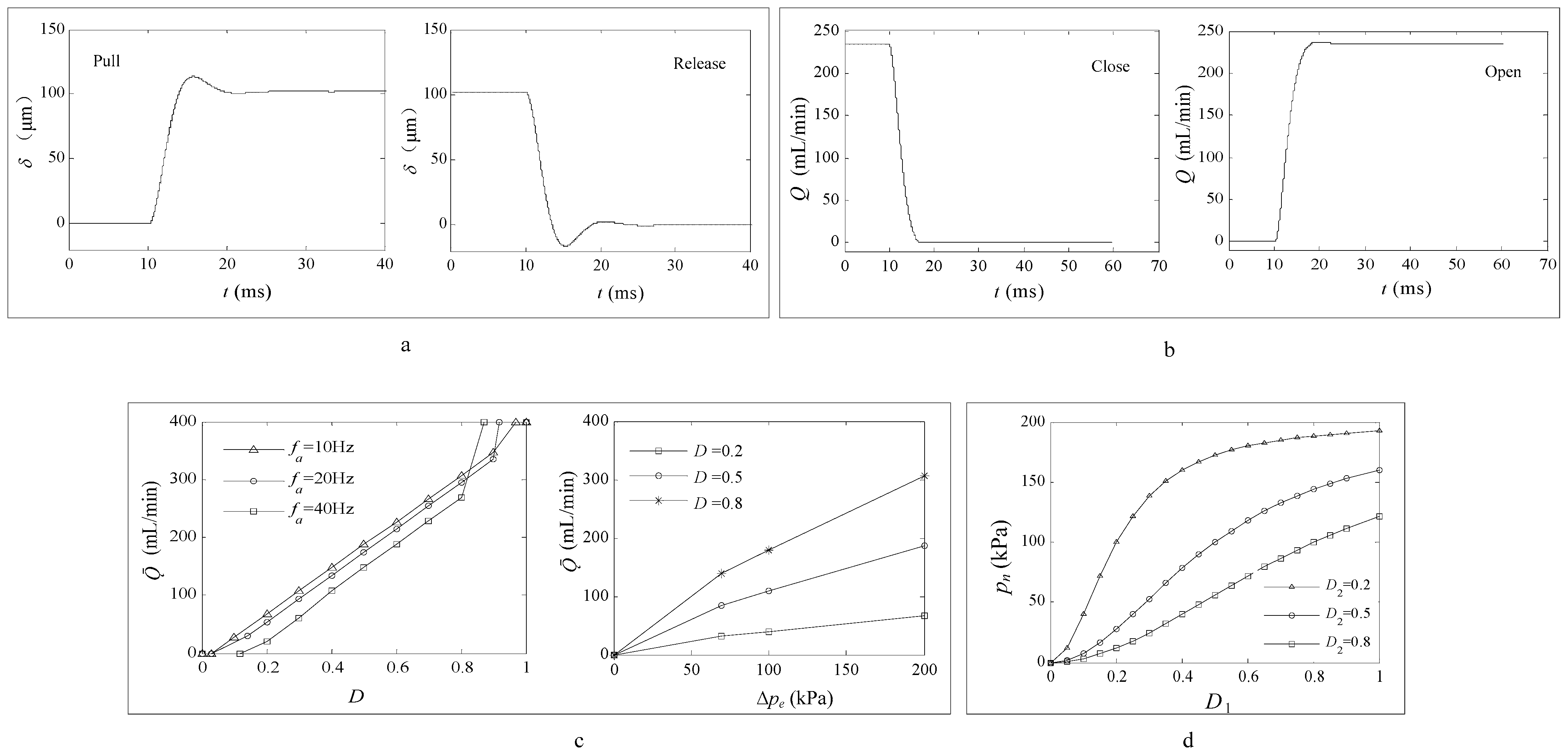
3.3. Dynamic Characteristic Simulation Results

The parameter names and values for the electromagnetic actuator and N2 used in this study for simulation and experiment are indicated in Table 2.
The simulation results of the dynamic response of the electromagnetic actuator are shown in Figure 3a. When the armature reaches the steady-state value for the first time, the closing time is about 4 ms, and the release time is about 3.5 ms. At the instant of the closing and releasing, there is a lag of about 1ms caused by the electromagnetic conversion. The simulation results show that the electromagnetic actuator has good dynamic response characteristics and a wide operating frequency.
When the armature is pulled in, the electromagnetic valve is open. When the armature is released, the electromagnetic valve is closed. The opening and closing time of the electromagnetic actuator reflects the response performance of the off-chip microvalve, and it is also a key parameter affecting the frequency characteristics of the off-chip microvalve. From the view of the response time, the working frequency of the off-chip microvalve can reach at least 105.26 Hz; that is, when the exciting pulse frequency is 105.26 Hz, the off-chip microvalve can be completely opened and closed with ample time. Taking the inlet pressure ps as 100 kPa and the outlet pressure pout as the ambient pressure, the simulation results of dynamic flow characteristics when the off-chip microvalve is opened and closed are shown in Figure 3b.
When using the PWM control method, the pulse frequency should be lower than the operating frequency of the off-chip microvalve (100 Hz). Figure 3c shows the flow–duty cycle and flow–pressure difference characteristics of the off-chip microvalve. On the left side of the picture is the change curve of duty cycle D and the average flow of the off-chip microvalve when the inlet pressure is 200 kPa and the PWM frequency fa is 10 Hz, 20 Hz, and 40 Hz. When the PWM frequency fa is 10 Hz, the average flow rate of the middle section of the off-chip microvalve output is almost linear with the duty cycle. When the PWM duty cycle D is less than 0.04, the off-chip microvalve works in the dead zone state; when the PWM duty cycle D is greater than 0.965, the off-chip microvalve works in the saturation state.
With the increase in PWM frequency, the linear regulation range of the effective pulse width duty ratio decreases, and the flow regulation range also decreases correspondingly. When fa changes from 10 Hz to 40 Hz, it has little influence on the average flow rate of the off-chip microvalve. With the decrease in the PWM frequency fa, the average flow rate of the off-chip microvalve increases slightly under the same duty cycle. The main reason is that the response delay time is reduced as the PWM frequency decreases. However, the PWM frequency changes caused by the flow of the change range are very small, so they can be ignored. Figure 3c on the right side shows the average flow–differential pressure characteristics of a single electromagnetic microvalve when the PWM frequency is 10 Hz and the duty ratio of pulse width is 0.2, 0.5, and 0.8. The average flow rate of the off-chip microvalve increases with the pressure difference and the duty ratio of the pulse width.
By adjusting the duty ratio of the two electromagnetic microvalves, which constitute the three-way microvalve, the change in the driving chamber pressure pn is controlled. The average output flow of the three-way microvalve Q12 is as follows:
Q 12 = Q 1 Q 2 = D 1 C e d A p 2 ( p s p n ) ρ g D 2 C e d A p 2 p n ρ g
In this study, the load of the three-way microvalve is driven by the membrane valve pneumatic microactuator cavity, and the load flow is zero. Setting Q12 = 0 in formula (7), the following is obtained:
p n = D 1 2 D 1 2 + D 2 2 p s
When the air source pressure ps is 200 kPa, the PWM duty cycle D2 of the off-chip electromagnetic microvalve 2 is 0.2, 0.5, and 0.8. The relationship between the load pressure pn and the PWM duty cycle D1 of the off-chip electromagnetic microvalve 1 is shown in Figure 3d. When the PWM duty cycle D2 of the off-chip microvalve 2 is constant and the PWM duty cycle D1 of the off-chip microvalve 1 is changed, the load pressure pn of the three-way microvalve can be changed. The smaller the PWM duty cycle D2 of electromagnetic microvalve 2 is, the more pronounced the nonlinear relationship between the PWM duty cycle D1 of electromagnetic microvalve 1 and the load pressure pn is. When the PWM duty cycle D2 of electromagnetic microvalve 2 is 0.5, its linear segment can be approximately considered to be in the interval of [0.25, 0.65]. When the PWM duty cycle D2 of electromagnetic microvalve 2 is 0.8, there is an apparent linear relationship between the load pressure pn and the PWM duty cycle D1 of electromagnetic microvalve 1. Its linear segment is approximately at [0.3, 0.8].
It can be seen from Equation (8) that both the flow–duty cycle characteristics and flow–pressure difference characteristics of a single electromagnetic microvalve and the relationship between the driving chamber pressure and PWM duty cycle when the three-way microvalve is connected with load are independent of PWM frequency. However, the size of the PWM frequency will affect the accuracy of flow regulation or pressure regulation, that is, affect the size of the valve port flow pulsation or pressure fluctuation, so the PWM frequency should be increased as much as possible, but subject to the dynamic characteristics of the proposed off-chip microvalve, PWM frequency can not exceed the maximum operating frequency of the electromagnetic driver (105.26 Hz). Otherwise, the electromagnetic drive can not wholly pull and release, affecting the performance of the off-chip microvalve. On the other hand, due to the full suction and discharge of the electromagnetic drive, the higher the frequency, the more serious the heating, which shortens the service life of the off-chip microvalve. Therefore, based on ensuring the performance of the off-chip microvalve, the PWM frequency should be reduced as much as possible. In this study, the maximum frequency of the PWM excitation signal used is not more than 100 Hz.

4. Experimental Study of the Off-Chip Microvalve

4.1. Sealing Strength of Valve Body and Fatigue Test of Valve Membrane

The seal strength of the PDMS valve body was tested, the body inlet was connected to the air supply, the output of the PDMS body was blocked by solidifying the PDMS prepolymer, and the entire valve body was immersed in deionized water until the water level was just over the top of the device. The inlet pressure was slowly adjusted from 0 to 200 kPa, which is the operating pressure range of the pneumatic microfluidic chip system, without obvious bubble overflow around the valve body. After 20 min, the pressure gauge value did not change significantly. The inlet pressure was increased to 280 kPa, and the test phenomenon was consistent with the aforementioned. When the inlet pressure was further increased, the side of the valve body broke open. After repeated tests, the test phenomenon was almost the same, indicating that the maximum working pressure that can be borne by the valve body is 280 kPa, and the pressure difference range can fully meet the pressure demand of the pneumatic microfluidic chip.
Ten encapsulated electromagnetic microvalves were used for the fatigue test of the valve membrane, and these microvalves were operated continuously for 2 h at 50 Hz frequency. The test results show that the valve membrane of one of the electromagnetic microvalves was broken at the contact point with the spool and was broken by the spool. The valve membrane of the other nine electromagnetic microvalves did not change significantly and remained intact. The operation of nine intact electromagnetic microvalves was continued at 50 Hz frequency for 1 h, and then the valve body and the electromagnetic actuator were decomposed for assessment, and the valve membrane was still intact. The broken valve membrane may have been caused by uneven mixing of PDMS prepolymer and uneven stress of the valve membrane itself. The experimental results show that the proposed microvalve has a long life span and can be used repeatedly for pneumatic control of microfluidic chips.

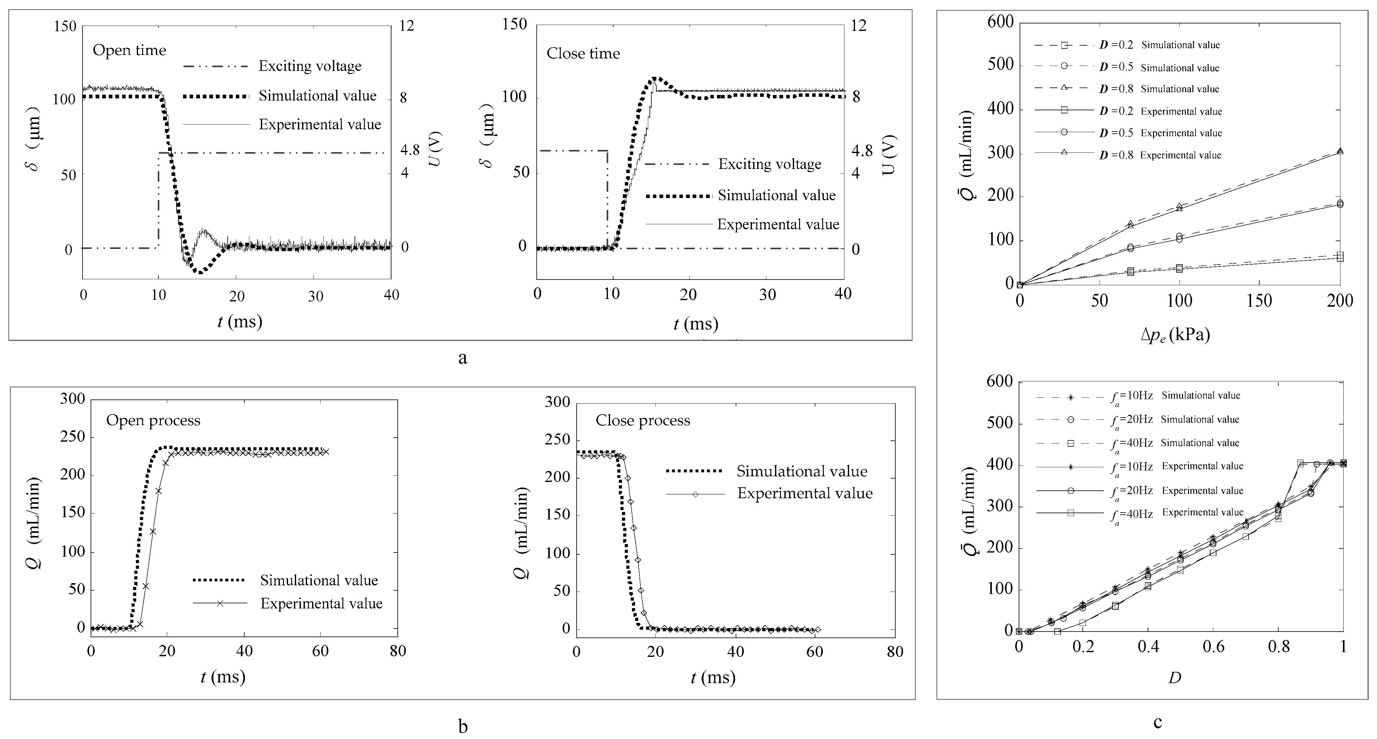
4.2. Experimental Study on Dynamic Characteristics

The parameters of the main equipment for testing the performance of single electromagnetic microvalves are listed in Table 3.
The displacement and response time were measured by the laser displacement sensor, which can achieve the accurate displacement resolution of 0.01 µm, and the sampling frequency was up to 393 kHz. The time axis reflects the response time of the electromagnetic microvalve, and the time resolution can be accurate to 0.01 ms. Moreover, the laser displacement sensor can measure the displacement change of non-transparent objects through transparent objects. In this test, the lower surface of the valve body was selected as the reference surface, and the valve core displacement was measured through the transparent PDMS valve body. The opening and closing excitation signal curves and the response time measurement results of the single electromagnetic microvalve are shown in Figure 4a. By comparing the excitation signal and the spool displacement test curve, the opening and closing times of the off-chip microvalve are found to be 5.90 ms and 4.05 ms, and the test results are almost consistent with the simulation results. Therefore, the highest working frequency of the single electromagnetic microvalve can reach 100 Hz. However, when comparing simulated results with experimental data, the former were smaller than the latter. The deviation between the simulation results and the experimental data could be due to the completely idealized simulation and the elastomer force of the PDMS material under the experimental condition. Another reason for this phenomenon is that the electromagnetic microvalve is an inductive component. When the electromagnetic microvalve is powered off, its stored magnetic energy is converted into electric energy, which causes a high electromotive force at the top of the electromagnetic actuator, resulting in a certain reverse displacement of the valve core. The response time is higher than that of a similar type of off-chip pneumatic microvalve [21,22,23,24,35].
The inlet pressure ps was 100 kPa, and the outlet pressure pout was the ambient pressure. The dynamic flow test results at the opening/closing moment of the single electromagnetic microvalve are shown in Figure 4b. The observed results show that the experimental values agree with the simulation data. At the opening/closing moment of the single electromagnetic microvalve, the exit flow test curve lags behind the simulation curve by about 2 ms. The reason for the lag is that, on the one hand, the electromagnetic conversion at the power-on/power-off moment of the electromagnetic drive takes time. On the other hand, the micro gas flow sensor ASF1430 adopts the principle of the temperature difference of hot film, with a built-in temperature compensation module and an entire calibration module. When dynamically measuring the micro gas flow rate, the internal force of the sensor needs a specific time of response to the heat transfer and amplification processing data. In addition, the experimental curve is undervalued during the opening process and overvalued during the closing process compared to the simulation cure. It is widely known that when the differential pressure is certain, the valve port flow is mainly related to the valve opening; the greater the valve opening, the larger the flow. The relaxation time of PDMS material itself affects the response time of the system to a certain extent, and this factor is ignored in the simulation. The elastic deformation and recovery deformation of the PDMS valve membrane take a certain amount of time during the opening and closing process of the microvalve. Therefore, the opening degree of the valve port has a certain lag, and so does the flow rate.
At the opening/closing moment of the single electromagnetic microvalve, ps was 200 kPa, pout was the ambient air pressure, and the PWM pulse signal was applied to the single electromagnetic microvalve. Figure 4c compares the test data and simulation results of flow–duty ratio characteristics of a single electromagnetic microvalve. As seen from the figure, with the increase in PWM pulse frequency, the range of the effective duty cycle (the average flow rate is linearly related to the duty cycle D of the PWM signal) decreases, and the average flow rate of the off-chip microvalve decreases slightly. The experimental data are in good agreement with the simulation results. When the duty cycle is small and large, there are dead zones and saturation phenomena. This phenomenon occurs due to the electromagnetic conversion delay that exists at the on–off moment and power-off moment of the electromagnetic actuator, and the inertia of the spool results in the spool not being able to be fully opened or closed.
Figure 4c also compares the test data of flow–differential pressure characteristics of a single electromagnetic microvalve with the simulation results. It can be seen from the figure that the average flow rate of the off-chip microvalve increases with the increase in differential pressure when the duty cycle is the same. Under the same pressure difference, the average flow rate of the single electromagnetic microvalve increases with the increase in the duty cycle of the pulse excitation signal. The experimental data showed that the model is consistent with the simulation results.

4.3. Experimental Performance of Mixing

The micromixer chip consists of an upper liquid layer and a lower control layer with a pneumatic microactuator and a PDMS-driven film between them. The proposed off-chip three-way microvalve in this study is used to control the vibration to thoroughly mix blue and yellow reagents in the micromixing chamber. If the blue reagent is more than the yellow reagent, the mixture will appear gray; otherwise, it will appear green. When the port connecting the three-way microvalve and the air source is opened, the compressed air enters the actuated chamber, and the PDMS thin membrane moves toward the micromixing chamber, which promotes the flow convection in the micromixing chamber and accelerates the mixing. The connection port between the three-way microvalve and the air source is closed, the port connecting the driving cavity and the atmosphere is opened, the pressure in the actuated chamber is reduced, the deformation of the PDMS membrane is recovered, and the extruded liquid returns to the micro-mixing chamber. By controlling the proposed three-way microvalve to control the vibration frequency of the mixing chamber, a variety of reagents in the micromixing chamber are quickly and fully mixed due to vibration convection. The gas source is closed by the off-chip three-way microvalve, and the samples of different colors in the micro-mixing chamber are in a state of natural convection. Detailed information about the results of natural convection mixing and vibration mixing can be found in our previous study [36].
A stereo-microscope with a CCD camera was used to acquire the digital images of the mixing process. The CCD camera was connected to an image processing system, which was used to quantify the mixing degree. The mixing efficiency was evaluated by the color offset (uniformity) of the digital image in the whole measured area. The color uniformity of the whole image was expressed by calculating the deviation between the gray scale of each pixel on the digital image and the gray scale of other pixels. The mixing efficiency quantization algorithm based on the digital image RGB color model, gray conversion model, and variance equation [37,38] is shown and corresponds to the blending pictures of those samples. In general, the mixing test at the microscale was completed at a relatively low vibration frequency. This is because the inlet microchannel connected to the pneumatic microactuator was very narrow, and the flow resistance was rather large, resulting in a longer inflation and exhaustion time. Therefore, the vibration frequency fm of the micromixer was set to 0.5 Hz, 1 Hz, and 2 Hz. Due to the large air resistance, if the vibration frequency is too high, the air pressure in the actuated chamber of the micromixer will be inflated or released too late, resulting in a small relative deformation of the PDMS thin membrane; in this case, the mixing efficiency will decrease and even tend to natural convection.
The excitation signal of the three-way microvalve when the actuated pressure pn was 20 kPa and the vibration frequency fm of the vibration micromixer was 0.5 Hz is shown in Figure 5a. In the middle of the picture is a CCD digital microscopic image as observed by human eyes. According to the quantitative mixing efficiency, the mixing efficiency reached 90.5% when the mixing time was 5 s. After 5 s, the mixing efficiency changed to around 94.6%.
The excitation signal of the off-chip three-way microvalve when the actuated pressure pn was 20 kPa and the vibration frequency fm was 1 Hz is shown in Figure 5b. As observed by the human eye, the color uniformity in the CCD digital microscopic image gradually showed a uniform trend with time. The mixing efficiency reached 94% when the mixing time was 5 s. After 5 s, the calculated mixing efficiency was about 94%.
The excitation signal of the off-chip three-way microvalve when the driving pressure pn was 20 kPa and the vibration frequency fm of the vibration micromixer was 2 Hz is shown in Figure 5c. As observed by the human eye, the color uniformity in the CCD digital microscopic image changes gradually with time, presenting a unified trend. According to the quantitative mixing efficiency, the mixing efficiency reached 94.8% when the mixing time was 5 s. After 5 s, the mixing efficiency changed to around 94.8%.
Based on Figure 5c, the experimental results show that the color uniformity of CCD digital microscopic images as perceived by human eyes gradually presents a uniform trend with the change in time. In the early stage of the mixing process, the first 5 s, under the same time condition, the higher the frequency, the higher the mixing efficiency; that is, at the same time, the longer the vibration time, the higher the mixing efficiency. Within 5 s to 10 s, the mixing efficiency is approximately 94%. As time passed after 10 s, the mixing efficiency changed little. It is found that when the driving pressure is 20 kPa, different driving pressure nearly does not affect the mixing efficiency. The mixing test results show that the PDMS pneumatic microactuator can be used as the actuated device of the on-chip micromixer with lower vibration frequency, preferably below 10 Hz, which can meet the pressure control requirements in most applications of pneumatic micro hybrid chips. Compared with the results of similar studies, the micromixer controlled by the proposed off-chip three-way microvalve has a shorter mixing time and higher mixing efficiency [39,40].

5. Conclusions and Future Work

In conclusion, a three-way microvalve with a simple architecture was proposed, and the characterization simulation results and appropriate experimental application of the pneumatic mixing process were presented. The dynamic coupling mathematical model of the electromagnetic microvalve was established based on the elastic deformation force of the valve membrane, the driving force of the spool, and the fluid power in the microchannel. Furthermore, the mathematical model of valve port flow was described, and its influencing factors were analyzed. The sealing strength of the valve body and fatigue of the valve membrane were tested, and the test results can guarantee the high repeatability and the reliability of the microvalve without a mechanical failure of the whole device or the puncturing of the valve membrane in the small strain region. The pull/release displacements of the valve core and the dynamic flow rate of the valve port were simulated and tested, reflecting the response time of the single microvalve. The closing time is about 4 ms, and the release time is about 3.5 ms, which can meet the needs of most applications of pneumatic microfluidic chips. Correlations between the flow rate of the single microvalve and the duty cycle of actuated signals, the average flow rate of the three-way microvalve, and the differential pressure of the valve port were investigated. The results show that the off-chip three-way microvalve can accurately control the pressure in the actuated chamber of a pneumatic microfluidic chip. This three-way microvalve requires less power and has higher speed, smaller volume, simpler structure, easier manufacture, and more convenient operation for precise airflow rate control than similar types of off-chip pneumatic microvalves. Liquid sample mixing was carried out to assess the capability of the three-way microvalve. The influence of vibration frequency on the mixing efficiency of reagents with different colors was studied and analyzed by experimental research. The mixing efficiency reaches 94.8% at 5s when the driving pressure is 20 kPa and the vibration frequency is 2 Hz. The successful mixing experiments in integrated microfluidic chips in this study show that the designed and simulated three-way microvalve can meet the pneumatic control requirements of a pneumatic microfluidic system. Moreover, the simplicity and high-precision pneumatic control permit the design of the integration of a valve array that can reduce the external pneumatic control system, decreasing the size of the overall pneumatic microfluidic system.

Author Contributions

Data curation, W.Z. and H.D.; Formal analysis, H.S.; Funding acquisition, J.S.; Investigation, T.S., L.W. and S.L.; Methodology, X.L. All authors have read and agreed to the published version of the manuscript.

Funding

This research was funded by the National Natural Science Foundation of China (Nos. 52005453 and 52075500), the Key Science and Technology Research Project of the Henan Province (222102310213), and the Science and Technology Project of the Henan Provincial Department of Transportation (No. 2020J2).

Data Availability Statement

The data presented in this study are available on request from the corresponding author.

Conflicts of Interest

The authors declare no conflict of interest.

Nomenclature

pnactuated chamber pressure (Pa)
ρndensity under 101.325 kPa and 21.1 °C (kg/m3)
Cvspecific heat at constant volume and 25 °C (kJ(kg·k))
αmolar entropy under 25 °C (J/(mol·k))
λthermal conductivity under 25 °C (W/(m·k))
Fhydrofluid power in the valve chamber (N)
k2elastic plate stiffness
h0initial height of the valve chamber (m)
Lvlength of the valve chamber (m)
Avarea of the valve membrane (m2)
μgdynamic air viscosity of the valve chamber (Pa∙s)
hdisplacement of the valve membrane (m)
pepressure differential (Pa)
Qair mass flow rate (kg/s)
kv1flow coefficient of valve-port
εpressure ratio
Rgas constant (J/(mol·k))
Kisentropic exponent
Dduty cycle of PWM
D2duty cycle of PWM of electromagnetic microvalve 1
Q1average inlet flow of three-way microvalve (m3/s)
Q12average output flow of three-way microvalve (m3/s)
fmvibration frequency of the micromixer
psair source pressure (Pa)
Cpspecific heat at constant pressure and 25 °C (kJ/(kg·k))
Cp/Cvspecific heat ratio
μviscosity under 25 °C (Pa·s)
Factuadriving force of the valve core (N)
Fmemelastic force of the valve membrane (N)
poutoutlet pressure of electromagnetic microvalve (Pa)
wvwidth of valve chamber (m)
γevalve-opening of electromagnetic microvalve
ρgfluid density of valve chamber (kg/m3)
δdisplacement of the valve core (m), δ = h
MMach number
φ(ε)N2 flow coefficient
kx1microscale correction coefficient before and after orifice
Apeffective area under harmony plug flow (m2)
Tstemperature of the air supply (K)
fafrequency of PWM (Hz)
D1duty cycle of PWM of the off-chip microvalve 1
Q ¯ average flow of the off-chip microvalve (m3/s)
Q2average outlet flow of three-way microvalve (m3/s)
ε*pressure ratio of upstream and downstream of valve port
Uexciting voltage of the three-way microvalve (V)
ttime (s)

References

  1. Shao, P.; Rummler, Z.; Schomburg, W.K. Polymer micro piezo valve with a small dead volume. J. Micromech. Microeng. 2003, 14, 305–309. [Google Scholar] [CrossRef]
  2. Anjewierden, D.; Liddiard, G.A.; Gale, B. An electrostatic microvalve for pneumatic control of microfluidic systems. J. Micromech. Microeng. 2012, 22, 025019. [Google Scholar] [CrossRef]
  3. Zheng, Y.; Dai, W.; Wu, H. A screw-actuated pneumatic valve for portable, disposable microfluidics. Lab Chip 2009, 9, 469–472. [Google Scholar] [CrossRef]
  4. Zeng, W.; Li, S.; Fu, H. Precise control of the pressure-driven flows considering the pressure fluctuations induced by the process of droplet formation. Microfluid. Nanofluid. 2018, 22, 133. [Google Scholar] [CrossRef]
  5. Bott, H.; Leonhardt, R.; Laermer, F.; Hoffmann, J. Employing fluorescence analysis for real-time determination of the volume displacement of a pneumatically driven diaphragm micropump. J. Micromech. Microeng. 2021, 31, 075003. [Google Scholar] [CrossRef]
  6. Guan, Y.; Yang, T.; Wu, J. Mixing and transport enhancement in microchannels by electrokinetic flows with charged surface heterogeneity. Phys. Fluids 2021, 33, 042006. [Google Scholar] [CrossRef]
  7. Stroock, A.D.; Whitesides, G.M. Components for integrated poly (dimethylsiloxane) microfluidic systems. Electrophoresis 2002, 23, 3461–3473. [Google Scholar]
  8. Zhong, J.F.; Chen, Y.; Marcus, J.S.; Scherer, A.; Quake, S.R.; Taylor, C.R.; Weiner, L.P. A microfluidic processor for gene expression profiling of single human embryonic stem cells. Lab Chip 2007, 8, 68–74. [Google Scholar] [CrossRef] [Green Version]
  9. Yang, T.; Peng, J.; Shu, Z.; Sekar, P.K.; Li, S.; Gao, D. Determination of the Membrane Transport Properties of Jurkat Cells with a Microfluidic Device. Micromachines 2019, 10, 832. [Google Scholar] [CrossRef] [Green Version]
  10. Grover, W.; Skelley, A.M.; Liu, C.N.; Lagally, E.T.; Mathies, R.A. Monolithic membrane valves and diaphragm pumps for practical large-scale integration into glass microfluidic devices. Sens. Actuators B Chem. 2003, 89, 315–323. [Google Scholar] [CrossRef]
  11. Kecskemeti, A.; Gaispar, A. Preparation and characterization of a packed bead immobilized trypsin reactor integrated into a PDMS microfluidic chip for rapid protein digestion. Alanta 2017, 166, 275–283. [Google Scholar] [CrossRef]
  12. Abrishamka, A.; Paradinas, M.; Bailo, E.; Trujillo, R.R.; Pfattner, R.; Rossi, R.M.; Ocal, C.; deMello, A.J.; Amabilino, D.B.; Luis, J.P. Microfluidic Pneumatic Cages: A Novel Approach for In-chip Crystal Trapping, Manipulation and Controlled Chemical Treatment. J. Vis. Exp. 2016, 113, e54193. [Google Scholar]
  13. Melin, J.; Quake, S.R. Microfluidic Large-Scale Integration: The Evolution of Design Rules for Biological Automation. Annu. Rev. Biophys. Biomol. Struct. 2007, 36, 213–231. [Google Scholar] [CrossRef] [Green Version]
  14. Wu, H.-W.; Lin, X.-Z.; Hwang, S.-M.; Lee, G.-B. The culture and differentiation of amniotic stem cells using a microfluidic system. Biomed. Microdevices 2009, 11, 869–881. [Google Scholar] [CrossRef]
  15. Tice, J.D.; Desai, A.V.; Bassett, T.A.; Apblett, C.A.; Kenis, P.J.A. Control of pressure-driven components in integrated microfluidic devices using an on-chip electrostatic microvalve. RSC Adv. 2014, 4, 51593–51602. [Google Scholar] [CrossRef]
  16. Selly, A.H. Colenoid actuators-further developments in extremely fast acting solenoids. SAE Trans. 1981, 90, 1770–1781. [Google Scholar]
  17. Liu, X.; Li, S. Control Method Experimental Research of Micro Chamber Air Pressure via a Novel Electromagnetic Microvalve. In Proceedings of the 2017 4th International Conference on Information Science and Control Engineering (ICISCE), Changsha, China, 21–23 July 2017; pp. 921–925. [Google Scholar]
  18. Zhang, Q.; Zhang, P.; Su, Y.; Mou, C.; Zhou, T.; Yang, M.; Xu, J.; Ma, B. On-demand control of microfluidic flow via capillary-tuned solenoid microvalve suction. Lab Chip 2014, 14, 4599–4603. [Google Scholar] [CrossRef]
  19. Cao, Z.; Chen, F.; Bao, N.; He, H.; Xu, P.; Jana, S.; Jung, S.; Lian, H.; Lu, C. Droplet sorting based on the number of encapsulated particles using a solenoid valve. Lab Chip 2013, 13, 171–178. [Google Scholar] [CrossRef]
  20. Chung, J.; Issadore, D.; Ullal, A.; Lee, K.; Weissleder, R.; Lee, H. Rare cell isolation and profiling on a hybrid magnetic/size-sorting chip. Biomicrofluidics 2013, 7, 054107. [Google Scholar] [CrossRef]
  21. Yang, B.; Lin, Q. A Latchable Phase-Change Microvalve with Integrated Heaters. J. Microelectromech. Syst. 2009, 18, 860–867. [Google Scholar] [CrossRef]
  22. Chia, B.T.; Liao, H.-H.; Yang, Y.-J. A novel thermo-pneumatic peristaltic micropump with low temperature elevation on working fluid. Sens. Actuators A Phys. 2011, 165, 86–93. [Google Scholar] [CrossRef]
  23. Gu, W.; Chen, H.; Tung, Y.-C.; Meiners, J.-C.; Takayama, S. Multiplexed hydraulic valve actuation using ionic liquid filled soft channels and Braille displays. Appl. Phys. Lett. 2007, 90, 033505. [Google Scholar] [CrossRef]
  24. Anjewierden, D. An Electrostatic Microvalve for Pneumatic Control of Microfluidic Systems. Master’s Thesis, University of Utah, Salt Lake City, UT, USA, 2011; pp. 58–59. [Google Scholar]
  25. Liu, X.; Li, S. An Electromagnetic Microvalve for Pneumatic Control of Microfluidic Systems. J. Lab. Autom. 2014, 19, 444–453. [Google Scholar] [CrossRef]
  26. Feng, Z.; Liu, X.; Li, S. Simulation on dynamic characteristics of a novel electromagnetic microvalve. Chin. Hydraul. Pneum. 2017, 10, 17–22. [Google Scholar]
  27. Li, S.; Liu, X.; Jia, W. Simulation on characteristics of a pneumatic electromagnetic microvalve. Chin. Hydraul. Pneum. 2013, 7, 6–8. [Google Scholar]
  28. Zhang, Y.; Chen, X. Blood cells separation microfluidic chip based on dielectrophoretic force. J. Braz. Soc. Mech. Sci. Eng. 2020, 42, 206. [Google Scholar] [CrossRef]
  29. Liu, X. Research of A Pdms Pneumatic Pressure Driven Microvalve and Applications in Pneumatic Mciro Mixing Chips. Ph.D. Thesis, Harbin Institute of Technology, Harbin, China, 2016; pp. 26–29. (In Chinese). [Google Scholar]
  30. Sun, L.; Siddique, M.K.; Wang, L.; Li, S. Mixing characteristics of a bubble mixing microfluidic chip for genomic DNA extraction based on magnetophoresis: CFD simulation and experiment. Electrophoresis 2021, 42, 2365–2374. [Google Scholar] [CrossRef]
  31. Zeng, W.; Jacobi, I.; Beck, D.J.; Li, S.; Stone, H.A. Characterization of syringe-pump-driven induced pressure fluctuations in elastic microchannels. Lab Chip 2015, 15, 1110–1115. [Google Scholar] [CrossRef]
  32. Mao, X. Research on Spatial Trajectory Control of Pneumatic Manipulator. Ph.D. Thesis, Harbin Institute of Technology, Harbin, China, 2010; pp. 3–4. (In Chinese). [Google Scholar]
  33. Li, L.; Li, H.; Kou, G.; Yang, D.; Hu, W.; Peng, J.; Li, S. Dynamic Camouflage Characteristics of a Thermal Infrared Film Inspired by Honeycomb Structure. J. Bionic Eng. 2022, 19, 458–470. [Google Scholar] [CrossRef]
  34. Chuang, H.S. Pneumatically-Driven Elastomeric Devices for a Programmable Lab on a Chip and Applications. Ph.D. Thesis, Purdue University, West Lafayette, IN, USA, 2010; pp. 32–37. [Google Scholar]
  35. Wiederkehr, R.S.; Salvadori, M.C.; Brugger, J.; Degasperi, F.T.; Cattani, M. Fabrication and testing of a poly(vinylidene fluoride) (PVDF) microvalve for gas flow control. Smart Mater. Struct. 2007, 16, 2302–2307. [Google Scholar] [CrossRef]
  36. Liu, X.; Zhang, D.; Liu, J.; Wang, L.; Li, S. RGB color model analysis for a simple structured polydimethylsiloxane pneumatic micromixer. Slas Technol. Transl. Life Sci. Innov. 2021, 26, 510–518. [Google Scholar] [CrossRef]
  37. Lee, Y.-K.; Tabeling, P.; Shih, C.; Ho, C.-M. Characterization of a MEMS-Fabricated Mixing Device. In Proceedings of the ASME 2000 International Mechanical Engineering Congress and Exposition, Orlando, FL, USA, 5–10 November 2000; pp. 505–511. [Google Scholar]
  38. Maliani, A.D.E.; Hassouni, M.E.; Berthoumieu, Y.; Aboutajdine, D. Generic multivariate model for color texture classification in RGB color space. Int. J. Multimed. Inf. Retr. 2014, 4, 217–231. [Google Scholar] [CrossRef] [Green Version]
  39. Nazari, M.; Rashidib, S.; Esfahania, J.A. Mixing process and mass transfer in a novel design of induced-charge electrokinetic micromixer with a conductive mixing-chamber. Int. Commun. Heat Mass Transf. 2019, 108, 104293. [Google Scholar] [CrossRef]
  40. Lee, C.-Y.; Fu, L.-M. Recent advances and applications of micromixers. Sens. Actuators B Chem. 2018, 259, 677–702. [Google Scholar] [CrossRef]
Figure 1. Schematic diagrams of the architecture and working states of the single microvalve: (a) electromagnetic microvalve open and closed states; (b) packaged electromagnetic actuator and microvalve; (c) operating condition of the three-way microvalve; (d) integration with a pneumatic micromixer.
Energies 15 08094 g001
Figure 2. Model of the valve-membrane force of the off-chip microvalve.
Energies 15 08094 g002
Figure 3. Dynamic characteristic simulation results: (a) armature pull and release dynamic response of the single electromagnetic microvalve; (b) dynamic flow rate of opening and closing process of the single electromagnetic microvalve; (c) duty cycle–flow rate and differential pressure–flow rate characteristics of the single electromagnetic microvalve with PWM; (d) relationships between the duty cycle of the electromagnetic 1 D1 and duty cycle of the electromagnetic 2 D2 of the three-way microvalve and the load pressure pn.
Energies 15 08094 g003
Figure 4. Comparison between experimental data on dynamic characteristics of the single electromagnetic microvalve and simulation results: (a) response time; (b) flow rate; (c) ǬD and Ǭ–Δpe characteristics.
Energies 15 08094 g004
Figure 5. Pictures and mixing efficiency Imix with different values of vibration frequency fm: (a) vibration frequency fm of 0.5 Hz; (b) vibration frequency fm of 1 Hz; (c) vibration frequency fm of 2 Hz.
Energies 15 08094 g005
Table 1. Parameters of the packaged electromagnetic microvalve.
Parameter NameParameter Value
Length of the electromagnetic actuator (mm)20.5
Width of the electromagnetic actuator (mm)9.8
Height of the electromagnetic actuator (mm)12.0
Diameter of the valve core (mm)1.0
Length of the microchannel (mm)20.0
Width of the microchannel (mm)0.5
Depth of the microchannel (mm)0.1
Thickness of the valve membrane (mm)0.1
Valve membrane: base/curing agent 15:1
Thickness of the PDMS thick block with a microchannel (mm)5.0
PDMS thick block with a microchannel: base/curing agent 8:1
Length of the encapsulated microvalve25.0
Width of the encapsulated microvalve9.8
Height of the encapsulated microvalve17.0
Table 2. Parameters of the electromagnetic actuator and N2.
TypeSymbolParameter NameOptimal Value
Electromagnetic actuatorμ0Air permeability (H/m)1.257 × 10−6
DArmature diameter (m)4.2 × 10⁻³
NTurns per coil (r)5100
lxArmature length (m)6 × 10⁻³
l0Non-working air gap length (m)0.65 × 10⁻³
rNon-working air gap average width (m)0.5 × 10⁻³
RMagnetic circuit equivalent resistance (Ω)550
uWorking voltage (V)24
δ0Spring preload (m)1.55 × 10⁻³
CvVelocity damping coefficient (N/(m/s))5
CfViscous damping coefficient of working medium (N/(m/s))0
mArmature weight (kg)30 × 10−3
k1Reset spring stiffness (N/m)7.5 × 102
N2ρnDensity under 101.325 kPa and 21.1 °C (kg/m3)1.160
CpSpecific heat under 25 °C (kJ/(kg·k))1.038
CvSpecific heat under 25 °C (kJ(kg·k))0.741
Cp/CvSpecific heat ratio 1.401
SonMolar entropy under 25 °C (J/(mol·k))191.5
μnViscosity under 25 °C (Pa·s)175.44 × 10⁷
λnThermal conductivity under 25 °C (W/(m·k))0.02475
Table 3. Parameters of the main equipment for testing the off-chip microvalve characteristics.
NameTypeKey ParametersManufacturer
Precision pressure-reducing valveIR1000-01Two-way type, measuring range 0.005~0.2 MPa, contact measurement mode, sensitivity: 0.2%F.s. Repetition accuracy within ±0.2%F.S.SMC
Miniature gas pressure sensorXCQ-062-30ADiameter: 1.7 mm, weight: 0.17 g, operating range: 0~3 × 10⁵ Pa, working mode: absolute pressure, natural frequency: 300 kHz.Kulite
Miniature gas flow sensorASF1430Dynamic measurement range: ±400 mL/min, maximum gas pressure: 29 psi (0.2 Mpa), minimum resolution: 0.0143 mL/min.Sensirion
Power supplyCustomizedDual channel, can be 0–10 V low voltage signal converted to −150V~+150 V high voltage signal.HIT
Laser displacement sensorLK-G5000Displacement resolution: 0.01 μm, time resolution: 0.01 ms, sampling frequency: 393 kHz.Keyence
Data acquisition cardPCI-1710-CE16 A/D input ports and 2 D/A output ports.Advantech
Publisher’s Note: MDPI stays neutral with regard to jurisdictional claims in published maps and institutional affiliations.

